experimental investigation on glass
DESCRIPTION
TRANSCRIPT
International Journal of Civil Engineering and Technology (IJCIET), ISSN 0976 – 6308
(Print), ISSN 0976 – 6316(Online) Volume 4, Issue 2, March - April (2013), © IAEME
321
EXPERIMENTAL INVESTIGATION ON GLASS
FIBRE REINFORCED PLASTICBRIDGE DECKS SUBJECTED
TO STATIC AND FATIGUE LOADING
Muthuraj. M. P.1, Subramanian. K
2
1Assistant Professor in Civil Engineering, Coimbatore Institute of Technology,
Coimbatore – 641 014, INDIA
2Professor and Head of Civil Engineering, Coimbatore Institute of Technology,
Coimbatore – 641 014, INDIA
ABSTRACT
This paper presents the details of experimental investigations carried out on Glass
Fibre Reinforced Polymer (GFRP) bridge decks subjected to static and fatigue loading. All
the beams have tested as per Indian Road Congress (IRC) Class A loading. The experimental
model is a one-third scaled model of a 3.75m bridge superstructure. Bridge deck panel of
span 1m is considered. The overall length and width of multi-cellular bridge deck panels are
kept as 1250 mm and 333.33 mm respectively. The overall dimensions have been arrived at
as per IRC code. The static and fatigue testing of prototype GFRP composite bridge deck
panels are carried out under the simulated wheel load of IRC Class A wheeled vehicle. Two
rectangular patch loads are applied symmetrically over the deck and the maximum deflection
under each panel under the factored load has been obtained. From the experiments, it is
observed that (i) the GFRP deck panel failed at an ultimate load of 123.6 kN with ultimate
deflection of 7.538mm under buckling criteria (ii) the GFRP deck panels failed at an ultimate
load of 113.8 kN with ultimate deflection of 4.057 mm under local shear criteria (ii) the
deflection within elastic limit is observed to be 1.627mm under buckling criteria and 0.902
under local shear criteria (iii) the GFRP deck panel resisted up to 5 million fatigue cycles and
(iv) the nature of failure is brittle for all the specimens. The experimental findings will be
useful for the design of bridge deck panels made up of GFRP.
INTERNATIONAL JOURNAL OF CIVIL ENGINEERING AND
TECHNOLOGY (IJCIET)
ISSN 0976 – 6308 (Print)
ISSN 0976 – 6316(Online)
Volume 4, Issue 2, March - April (2013), pp. 321-331
© IAEME: www.iaeme.com/ijciet.asp
Journal Impact Factor (2013): 5.3277 (Calculated by GISI) www.jifactor.com
IJCIET
© IAEME
International Journal of Civil Engineering and Technology (IJCIET), ISSN 0976 – 6308
(Print), ISSN 0976 – 6316(Online) Volume 4, Issue 2, March - April (2013), © IAEME
322
1. INTRODUCTION
The choice of composite materials as a substitute for metallic materials in structural
applications is becoming more pronounced especially due to the great weight savings that
these materials offer. Polymer matrix composites have material properties which are
attractive for use in various engineering applications especially in aerospace, marine,
automobile and civil engineering. Many of the applications require serviceability under
dynamic loading conditions. The research undertaken during the last two decades has shown
that, one of the potential solutions to the steel-corrosion-related problems in concrete is the
use of Fibre Reinforced Polymer (FRP) composites as a replacement for traditional steel bars.
GFRP is gaining more popularity in construction of bridges, because bridge deck slabs are
one of the most severely affected components in reinforced concrete structures. Since the
material offers unique combination of high strength to weight ratio and stiffness to weight
ratio, corrosion and fatigue resistance, improved long-term performance to environmental
effects, lower maintenance cost, longer service life, lower life-cycle costs, it makes them
attractive for use in the construction of new slabs and retrofitting and rehabilitation of
existing slab panels, and also in other concrete structures. In addition they have strong
potential for use in earthquake vulnerable zones, and also in places where longer unsupported
spans are required.
The light weight composite bridges can be transported easily. Since composites will
not chip like concrete or rust like steel, the maintenance associated with this advanced
material is completely eliminated. Extensive research studies were carried out on FRP for
different applications1-7
. Zheng et al8 developed a simplified trilinear relationship between
moment and curvature for FRP beams. The analysis results from this relationship were
compared with the test data from five concrete beams reinforced with glass fiber reinforced
polymer (GFRP) rebars tested under two-thirds-point flexure until failure. The comparisons
were indicated that the suggested relationship yields good predictions of flexural capacity of
all beams. Wang and Kodur9 presented the results of tensile mechanical properties of FRP
reinforcement bars, used as internal reinforcement in concrete structures, at elevated
temperatures. Detailed experimental studies were conducted to determine the strength and
stiffness properties of FRP bars at elevated temperatures. Ochola et al10
evaluated the
mechanical properties of glass and carbon fibre reinforced composites at varying strain rates
by testing a single laminate configuration. The compressive material properties were
determined by testing both laminate systems, viz. CFRP and GFRP at low to high strain rates.
Preliminary compressive stress–strain vs. strain rates data obtained showed that the dynamic
material strength for GFRP increases with increasing strain rates. The strain to failure for
both CFRP and GFRP is observed to decrease with increasing strain rate. Berg et al11
described the use of FRP materials as reinforcements and formwork for a concrete highway
bridge deck. Three forms of FRP reinforcing were combined to reinforce the concrete deck:
FRP stay-in-place (SIP) forms, deformed FRP reinforcing bars (rebars), and a special
prefabricated pultruded FRP reinforcing grid. Nanni and Norris12
conducted experiments to
evaluate the behaviour of concrete members laterally confined with fibre-reinforced plastic
(FRP) composites. Specimens were loaded quasi-statically under cyclic flexure with and
without axial compression. It was found that flexural strength and ductility are enhanced by
the use of FRP jackets. It was noted that improvements depend on jacketing method, shape of
member cross-section, level of the axial load, and failure mode. Smitha et al13
reported a
series of tests on one-way spanning simply supported RC slabs which were strengthened in
International Journal of Civil Engineering and Technology (IJCIET), ISSN 0976 – 6308
(Print), ISSN 0976 – 6316(Online) Volume 4, Issue 2, March - April (2013), © IAEME
323
flexure with tension face bonded FRP composites and anchored with different arrangements
of FRP anchors. The greatest enhancement in load and deflection experienced by the six slabs
strengthened with FRP plates and anchored with FRP anchors was 30% and 110%,
respectively, over the unanchored FRP-strengthened control slab. Lu et al14
presented
numerical study of the FRP stress distribution at debonding failure in U-jacketed or side-
bonded beams using a rigorous FRP-to-concrete bond–slip model and assuming several
different crack width distributions. Mazzotti et al15
carried out an experimental study on
delamination of FRP plates bonded to concrete. Experimental tests were simulated by
adopting a numerical bond-slip model and observed that numerical results are in good
agreement with experimental results. Diab and Wu16
developed a new nonlinear viscoelastic
model for the study of the long-term behavior of the FRP-concrete interface. The model has
the ability to describe the creep of the FRP-concrete adhesive layer and the creep fracture
propagation along the FRP-concrete interface. Abdalla17
developed simple analytical
methodology to compute the deflection in FRP reinforced members subjected to flexural
stresses and compared with the corresponding experimental results. Luciano and Sacco18
proposed a numerical model to study the mechanical behaviour of a masonry wall. To mode1
the overall behavior of the unreinforced and reinforced masonry, by accounting for the
progressive damage of the mortar, of the block and of the FRP sheets, a simple
homogenization technique was proposed. Two different damage criteria were adopted for the
mortar and the block, within isotropic viscoelastic and elastic damage models.
From the literature review, it is observed that the experimental studies on the
behaviour of hand lay-up GFRP composite bridge deck panels under static and fatigue
loading is limited. The present study is aimed at to conduct experiments on the performance
of a scaled model of a GFRP bridge deck under static and fatigue loading.
2. MATERIALS AND ITS PROPERTIES
The most extensively used class of fibres in composites is those manufactured from
E-glass. E-glass is a low alkali borosilicate glass originally developed for electrical insulation
applications. It was first produced commercially for composite manufacture in 1940’s, and its
use now approaches 2 MT/year worldwide. Many different countries manufacture E-glass
and its exact composition varies according to the availability and composition of the local
raw materials. It is manufactured as continuous filaments in bundles, or strands, each
containing typically between 200 and 2000 individual filaments of 10-30 µm diameters.
These strands will be incorporated into larger bundles called roving and may be processed
into a wide variety of mats, cloths, and performs and cut into short-fibre formats. The degree
to which the fibres are bound together in the strand is controlled by the size. The choice of a
size compatible with the matrix resin and process route is thus of critical importance when
sourcing reinforcements. Woven clothes and rovings are very widely used in the manufacture
of laminated structures. In-plane strengths are much higher than for the random materials.
Stiffness, strength, and drape are also influenced by the weave pattern. The plain weave leads
to a high degree of crimp, which may reduce stiffness by up to about 15% compared with a
similar fraction of straight fibres. Twill and satin weaves offer better drape, and the satin
weaves in particular have less crimp.
Five and eight-harness satin weaves are widely used in composite laminates,
especially in the lighter weights, which are more appropriate in many highly stressed designs.
The tighter fibre structure in cloths renders them more difficult to infiltrate and consolidate
International Journal of Civil Engineering and Technology (IJCIET), ISSN 0976 – 6308
(Print), ISSN 0976 – 6316(Online) Volume 4, Issue 2, March - April (2013), © IAEME
324
than the random mats. WR fabrics are specifically designed to meet most demanding
performance, processing and cost requirements. These fabrics deliver a unique combination
of properties. They offer one of the highest strength-to-weight ratios possible for reinforced
plastics and through careful selection and placement of fabrics, designers can put the strength
exactly where it is needed, making optimum use of the fibre strength. Woven roving fabrics
provide the most economical solution for raising glass content of laminates and increasing
laminate stiffness and impact resistance without adding thickness, weight or other non-
reinforcing materials. ERs are used in advanced applications including aircraft, aerospace,
and defense, as well as many of the first- generation composite reinforcing concrete products
currently available in the market. ERs are available in a range of viscosities, and will work
with a number of curing agents or hardeners. The nature of epoxy allows it to be manipulated
into a partially-cured or advanced cure state commonly known as a “prepreg”. If the prepreg
also contains the reinforcing fibres the resulting tacky lamina can be positioned on a mold (or
wound if it is in the form of a tape) at room temperature. Although some epoxies harden at
temperatures as low as 80oF (30oC), all epoxies require some degree of heated post-cure to
achieve satisfactory high temperature performance. Large parts fabricated with ER exhibit
good fidelity to the mold shape and dimensions of the molded part. ERs can be formulated to
achieve very high mechanical properties. However, certain hardeners (particularly amines),
as well as the ERs themselves, can be skin sensitizing, so appropriate personal protective
procedures must always be followed. Some epoxies are also more sensitive to moisture and
alkali. This behaviour must be taken into account in determining long term durability and
suitability for any given application. Curing time and increased temperature required to
complete cross-linking (polymerisation) depend on the type and amount of hardener used.
Some hardeners will work at room temperature. However, most hardeners require elevated
temperatures. Additives called accelerators are sometimes added to the liquid ER to speed up
reactions and decrease curing cycle times. The heat resistance of an epoxy is improved if it
contains more aromatic rings in its basic molecular chain. If the curing reaction of ERs is
slowed by external means, (i.e., by lowering the reaction temperature) before all the
molecules are cross-linked, the resin would be in what is called a B-staged form. In this form,
the resin has formed cross-links at widely spaced positions in the reactive mass, but is
essentially uncured. Hardness, tackiness, and the solvent reactivity of these B-staged resins
depend on the degree of curing. Various material properties are presented in Table 1.
3. CROSS SECTIONAL PROFILE
The overall dimensions are arrived at based on the Indian Road Congress (IRC) code
IRC:6-2000. The experimental model is a one-third scale model of a 3.75m bridge
superstructure. Bridge deck panel of span 1m is considered. The overall length and width of
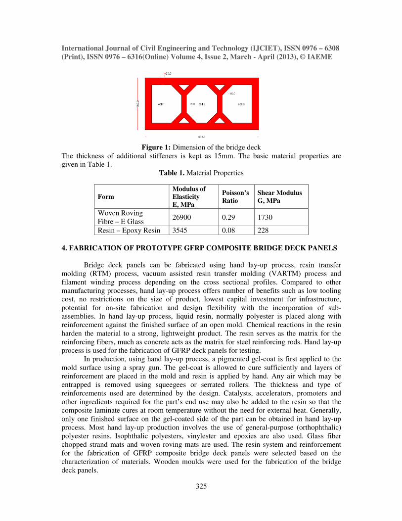
multicellular bridge deck panels are kept as 1250 mm and 333.33 mm respectively. A cross
sectional profile as shown in Figure 1 with minimum weight is selected for the fabrication
and experimental investigation. The cross section consists of a 3-cell rectangular section with
additional stiffeners connecting the web to the top and bottom flange. The thickness of the
top flange, bottom flange and webs are kept as 20 mm and web as 15mm (Figure 1).
International Journal of Civil Engineering and Technology (IJCIET), ISSN 0976 – 6308
(Print), ISSN 0976 – 6316(Online) Volume 4, Issue 2, March - April (2013), © IAEME
325
Figure 1: Dimension of the bridge deck
The thickness of additional stiffeners is kept as 15mm. The basic material properties are
given in Table 1.
Table 1. Material Properties
Form
Modulus of
Elasticity
E, MPa
Poisson’s
Ratio
Shear Modulus
G, MPa
Woven Roving
Fibre – E Glass 26900 0.29 1730
Resin – Epoxy Resin 3545 0.08 228
4. FABRICATION OF PROTOTYPE GFRP COMPOSITE BRIDGE DECK PANELS
Bridge deck panels can be fabricated using hand lay-up process, resin transfer
molding (RTM) process, vacuum assisted resin transfer molding (VARTM) process and
filament winding process depending on the cross sectional profiles. Compared to other
manufacturing processes, hand lay-up process offers number of benefits such as low tooling
cost, no restrictions on the size of product, lowest capital investment for infrastructure,
potential for on-site fabrication and design flexibility with the incorporation of sub-
assemblies. In hand lay-up process, liquid resin, normally polyester is placed along with
reinforcement against the finished surface of an open mold. Chemical reactions in the resin
harden the material to a strong, lightweight product. The resin serves as the matrix for the
reinforcing fibers, much as concrete acts as the matrix for steel reinforcing rods. Hand lay-up
process is used for the fabrication of GFRP deck panels for testing.
In production, using hand lay-up process, a pigmented gel-coat is first applied to the
mold surface using a spray gun. The gel-coat is allowed to cure sufficiently and layers of
reinforcement are placed in the mold and resin is applied by hand. Any air which may be
entrapped is removed using squeegees or serrated rollers. The thickness and type of
reinforcements used are determined by the design. Catalysts, accelerators, promoters and
other ingredients required for the part’s end use may also be added to the resin so that the
composite laminate cures at room temperature without the need for external heat. Generally,
only one finished surface on the gel-coated side of the part can be obtained in hand lay-up
process. Most hand lay-up production involves the use of general-purpose (orthophthalic)
polyester resins. Isophthalic polyesters, vinylester and epoxies are also used. Glass fiber
chopped strand mats and woven roving mats are used. The resin system and reinforcement
for the fabrication of GFRP composite bridge deck panels were selected based on the
characterization of materials. Wooden moulds were used for the fabrication of the bridge
deck panels.
International Journal of Civil Engineering and Technology (IJCIET), ISSN 0976 – 6308
(Print), ISSN 0976 – 6316(Online) Volume 4, Issue 2, March - April (2013), © IAEME
326
The cross section of the GFRP composite bridge deck panel is a multicellular
rectangular section with additional stiffeners connecting the web to the top flange and the
cross sectional dimensions were obtained based on the finite element analysis. The
dimensions of GFRP bridge deck panel are shown in Fig. 1 and Table 2, Wooden moulds are
cheap, light in weight and easy to fabricate than other types of moulds made using steel and
FRP composite materials.
Table 2. GFRP Brick Deck Panel Dimensions
PARAMETER PROTOTYPE
(mm)
MODEL
(mm)
Length 3750 1250
Width 1000 333.333
Depth 450 150
Flange & outer web Thickness 30 20
Inner web thickness 45 15
Additional stiffeners 45 15
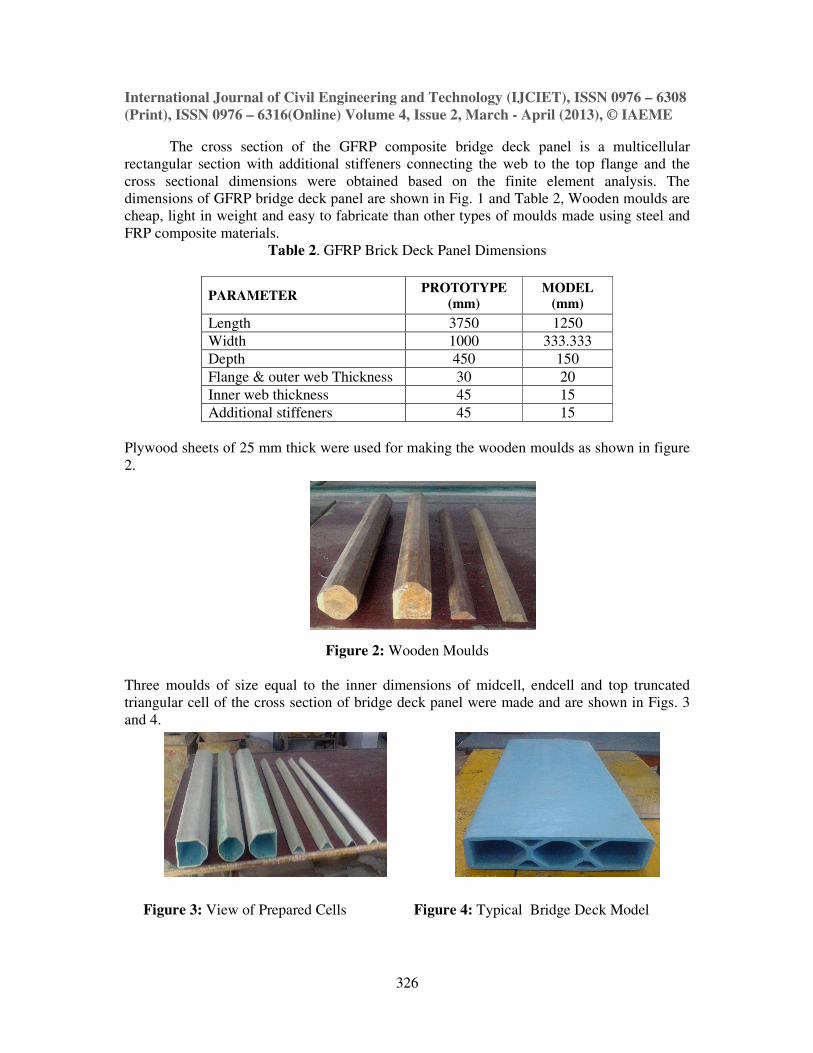
Plywood sheets of 25 mm thick were used for making the wooden moulds as shown in figure
2.
Figure 2: Wooden Moulds
Three moulds of size equal to the inner dimensions of midcell, endcell and top truncated
triangular cell of the cross section of bridge deck panel were made and are shown in Figs. 3
and 4.
Figure 3: View of Prepared Cells Figure 4: Typical Bridge Deck Model
International Journal of Civil Engineering and Technology (IJCIET), ISSN 0976
(Print), ISSN 0976 – 6316(Online) Volume 4, Issue 2, March
The surfaces of the wooden moulds were polished using the rough and smooth files
and with sand grit papers. Duco putty was
the mould surface. Wooden moulds were
papers to get the smooth polished
5. FABRICATION AND TESTING
The surfaces of the wooden molds were polished using the rough and smooth files and
with sand grit papers. Duco putty was
mold surface. Wooden molds were polished again with smooth and rough water emery papers
to get the smooth polished surfaces for the fabrication of products. The surface of the mould
is first polished and treated with a suitable mould release agent to prevent the moulding resin
from sticking to the mould surface. Wax polishes are widely used for polishing the mould,
and these also act as good release agents for many resins. In many cases, a layer of
unreinforced resin is applied directly to the mould surface to form a gel coat. This helps to
produce a good surface finish on the moulding and prevents print through the reinforcement
Gel coats may also enhance the durability and corrosion resistance of the moul
reducing the absorption of water and solvents into the materials during exposure in service.
Additionally, gel coats may be pigmented or coloured to produce a self
typical fabricated prototype bridge deck panels
loading pattern and typical test set
frame was connected to the strong test floor.
Proving ring of 300kN capacity was used
applied on the model. Two GFRP panels were tested under static loading and one panel was
tested under fatigue loading. Two rectangular patch loads is applied symmetrically over the
deck and the maximum deflection under each panel under the factored load is obtained.
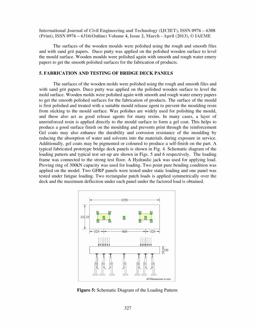
Figure 5: Schematic Diagram of the Loading Pattern
International Journal of Civil Engineering and Technology (IJCIET), ISSN 0976
6316(Online) Volume 4, Issue 2, March - April (2013), © IA
327
The surfaces of the wooden moulds were polished using the rough and smooth files
Duco putty was applied on the polished wooden surface to level
the mould surface. Wooden moulds were polished again with smooth and rough wate
papers to get the smooth polished surfaces for the fabrication of products.
AND TESTING OF BRIDGE DECK PANELS
The surfaces of the wooden molds were polished using the rough and smooth files and
with sand grit papers. Duco putty was applied on the polished wooden surface to level the
mold surface. Wooden molds were polished again with smooth and rough water emery papers
to get the smooth polished surfaces for the fabrication of products. The surface of the mould
treated with a suitable mould release agent to prevent the moulding resin
from sticking to the mould surface. Wax polishes are widely used for polishing the mould,
and these also act as good release agents for many resins. In many cases, a layer of
orced resin is applied directly to the mould surface to form a gel coat. This helps to
produce a good surface finish on the moulding and prevents print through the reinforcement
Gel coats may also enhance the durability and corrosion resistance of the moul
reducing the absorption of water and solvents into the materials during exposure in service.
Additionally, gel coats may be pigmented or coloured to produce a self-finish on the part.
fabricated prototype bridge deck panels is shown in Fig. 4. Schematic diagram of the
loading pattern and typical test set-up are shown in Figs. 5 and 6 respectively.
frame was connected to the strong test floor. A Hydraulic jack was used for a
0kN capacity was used for loading. Two point pure bending condition was
Two GFRP panels were tested under static loading and one panel was
Two rectangular patch loads is applied symmetrically over the
ection under each panel under the factored load is obtained.
Schematic Diagram of the Loading Pattern
International Journal of Civil Engineering and Technology (IJCIET), ISSN 0976 – 6308
April (2013), © IAEME
The surfaces of the wooden moulds were polished using the rough and smooth files
applied on the polished wooden surface to level
polished again with smooth and rough water emery
The surfaces of the wooden molds were polished using the rough and smooth files and
applied on the polished wooden surface to level the
mold surface. Wooden molds were polished again with smooth and rough water emery papers
to get the smooth polished surfaces for the fabrication of products. The surface of the mould
treated with a suitable mould release agent to prevent the moulding resin
from sticking to the mould surface. Wax polishes are widely used for polishing the mould,
and these also act as good release agents for many resins. In many cases, a layer of
orced resin is applied directly to the mould surface to form a gel coat. This helps to
produce a good surface finish on the moulding and prevents print through the reinforcement
Gel coats may also enhance the durability and corrosion resistance of the moulding by
reducing the absorption of water and solvents into the materials during exposure in service.
finish on the part. A
. Schematic diagram of the
respectively. The loading
A Hydraulic jack was used for applying load.
for loading. Two point pure bending condition was
Two GFRP panels were tested under static loading and one panel was
Two rectangular patch loads is applied symmetrically over the
ection under each panel under the factored load is obtained.
International Journal of Civil Engineering and Technology (IJCIET), ISSN 0976
(Print), ISSN 0976 – 6316(Online) Volume 4, Issue 2, March
The static testing of prototype GFRP composite bridge deck panels was carried out
under the simulated wheel load of IRC Class A wheeled vehicle. The dead load of future
wearing surface was calculated. The dynamic allowance factor was taken as 30% of the live
load of the wheeled vehicle. The static tests were conducted under a factored load of
(wheel load + 30% of impact factor (assumed) + dead load including future wearing surface)
applied over the bridge deck panel from zero to factored load of
Fig. 7
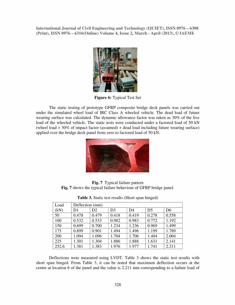
Fig. 7 shows the typical failure behaviour of GFRP bridge pane
Table 3.
Deflections were measured using LVDT.
short span hinged. From Table 3, it can be
centre at location 6 of the panel and the value is
Load
(kN)
Deflection (mm)
D1 D2
50 0.478 0.479
100 0.532 0.533
150 0.699 0.700
175 0.899 0.901
200 1.094 1.096
225 1.301 1.304
252.6 1.381 1.383
International Journal of Civil Engineering and Technology (IJCIET), ISSN 0976
6316(Online) Volume 4, Issue 2, March - April (2013), © IA
328
Figure 6: Typical Test Set
The static testing of prototype GFRP composite bridge deck panels was carried out
eel load of IRC Class A wheeled vehicle. The dead load of future
wearing surface was calculated. The dynamic allowance factor was taken as 30% of the live
load of the wheeled vehicle. The static tests were conducted under a factored load of
ad + 30% of impact factor (assumed) + dead load including future wearing surface)
applied over the bridge deck panel from zero to factored load of 50 kN.
Fig. 7 Typical failure pattern
shows the typical failure behaviour of GFRP bridge panel.
Static test results (Short span hinged)
Deflections were measured using LVDT. Table 3 shows the static test results with
short span hinged. From Table 3, it can be noted that maximum deflection occurs at the
of the panel and the value is 2.211 mm corresponding to a failure load of
Deflection (mm)
D2 D3 D4 D5 D6
0.479 0.418 0.419 0.278 0.558
0.533 0.982 0.983 0.772 1.192
0.700 1.234 1.236 0.969 1.499
0.901 1.494 1.496 1.199 1.789
1.096 1.704 1.706 1.404 2.004
1.304 1.886 1.888 1.631 2.141
1.383 1.976 1.977 1.741 2.211
International Journal of Civil Engineering and Technology (IJCIET), ISSN 0976 – 6308
April (2013), © IAEME
The static testing of prototype GFRP composite bridge deck panels was carried out
eel load of IRC Class A wheeled vehicle. The dead load of future
wearing surface was calculated. The dynamic allowance factor was taken as 30% of the live
load of the wheeled vehicle. The static tests were conducted under a factored load of 50 kN
ad + 30% of impact factor (assumed) + dead load including future wearing surface)
Table 3 shows the static test results with
noted that maximum deflection occurs at the
failure load of
0.558
1.192
1.499
1.789
2.004
2.141
2.211
International Journal of Civil Engineering and Technology (IJCIET), ISSN 0976 – 6308
(Print), ISSN 0976 – 6316(Online) Volume 4, Issue 2, March - April (2013), © IAEME
329
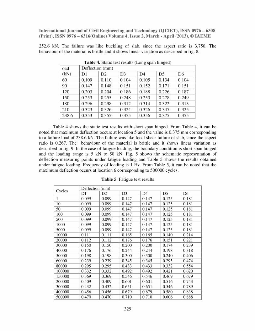
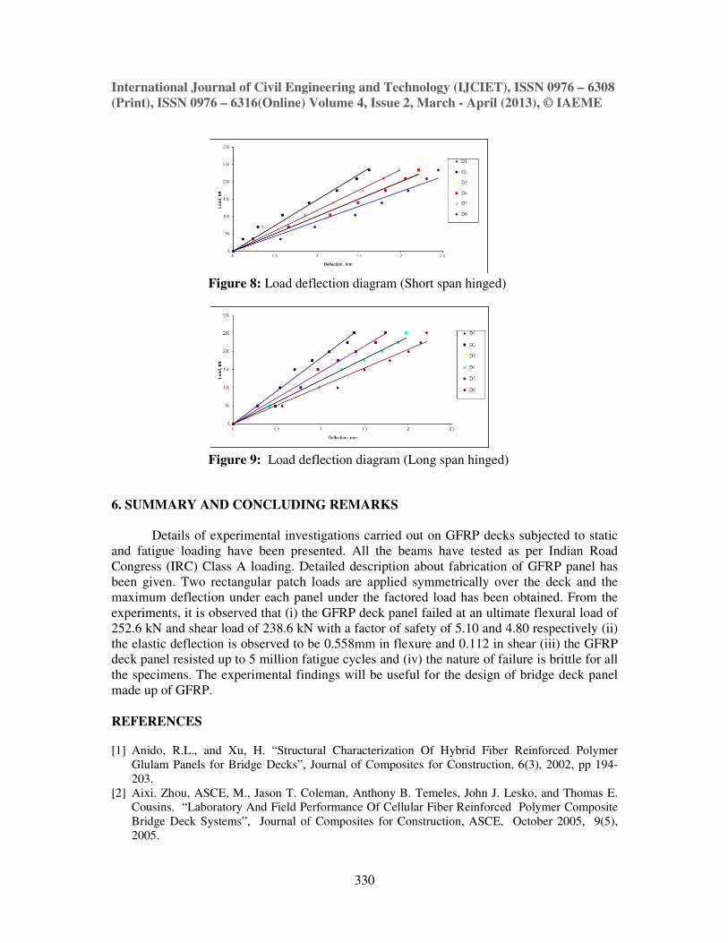
252.6 kN. The failure was like buckling of slab, since the aspect ratio is 3.750. The
behaviour of the material is brittle and it shows linear variation as described in fig. 8.
Table 4. Static test results (Long span hinged)
oad
(kN)
Deflection (mm)
D1 D2 D3 D4 D5 D6
60 0.109 0.110 0.104 0.105 0.134 0.104
90 0.147 0.148 0.151 0.152 0.171 0.151
120 0.203 0.204 0.186 0.188 0.226 0.187
150 0.253 0.255 0.248 0.250 0.278 0.249
180 0.296 0.298 0.312 0.314 0.322 0.313
210 0.323 0.326 0.324 0.326 0.347 0.325
238.6 0.353 0.355 0.355 0.356 0.375 0.355
Table 4 shows the static test results with short span hinged. From Table 4, it can be
noted that maximum deflection occurs at location 5 and the value is 0.375 mm corresponding
to a failure load of 238.6 kN. The failure was like local shear failure of slab, since the aspect
ratio is 0.267. The behaviour of the material is brittle and it shows linear variation as
described in fig. 9. In the case of fatigue loading, the boundary condition is short span hinged
and the loading range is 5 kN to 50 kN. Fig. 5 shows the schematic representation of
deflection measuring points under fatigue loading and Table 5 shows the results obtained
under fatigue loading. Frequency of loading is 1 Hz. From Table 5, it can be noted that the
maximum deflection occurs at location 6 corresponding to 500000 cycles.
Table 5. Fatigue test results
Cycles Deflection (mm)
D1 D2 D3 D4 D5 D6
1 0.099 0.099 0.147 0.147 0.125 0.181
10 0.099 0.099 0.147 0.147 0.125 0.181
50 0.099 0.099 0.147 0.147 0.125 0.181
100 0.099 0.099 0.147 0.147 0.125 0.181
500 0.099 0.099 0.147 0.147 0.125 0.181
1000 0.099 0.099 0.147 0.147 0.125 0.181
5000 0.099 0.099 0.147 0.147 0.125 0.181
10000 0.111 0.111 0.165 0.165 0.140 0.214
20000 0.112 0.112 0.176 0.176 0.151 0.221
30000 0.150 0.150 0.200 0.200 0.174 0.239
40000 0.176 0.176 0.244 0.244 0.198 0.318
50000 0.198 0.198 0.300 0.300 0.240 0.406
60000 0.239 0.239 0.345 0.345 0.295 0.474
80000 0.295 0.295 0.433 0.433 0.332 0.554
100000 0.332 0.332 0.492 0.492 0.421 0.620
150000 0.369 0.369 0.546 0.546 0.469 0.679
200000 0.409 0.409 0.601 0.601 0.516 0.743
300000 0.432 0.432 0.651 0.651 0.546 0.789
400000 0.456 0.456 0.679 0.679 0.580 0.838
500000 0.470 0.470 0.710 0.710 0.606 0.888
International Journal of Civil Engineering and Technology (IJCIET), ISSN 0976 – 6308
(Print), ISSN 0976 – 6316(Online) Volume 4, Issue 2, March - April (2013), © IAEME
330
Figure 8: Load deflection diagram (Short span hinged)
Figure 9: Load deflection diagram (Long span hinged)
6. SUMMARY AND CONCLUDING REMARKS
Details of experimental investigations carried out on GFRP decks subjected to static
and fatigue loading have been presented. All the beams have tested as per Indian Road
Congress (IRC) Class A loading. Detailed description about fabrication of GFRP panel has
been given. Two rectangular patch loads are applied symmetrically over the deck and the
maximum deflection under each panel under the factored load has been obtained. From the
experiments, it is observed that (i) the GFRP deck panel failed at an ultimate flexural load of
252.6 kN and shear load of 238.6 kN with a factor of safety of 5.10 and 4.80 respectively (ii)
the elastic deflection is observed to be 0.558mm in flexure and 0.112 in shear (iii) the GFRP
deck panel resisted up to 5 million fatigue cycles and (iv) the nature of failure is brittle for all
the specimens. The experimental findings will be useful for the design of bridge deck panel
made up of GFRP.
REFERENCES
[1] Anido, R.L., and Xu, H. “Structural Characterization Of Hybrid Fiber Reinforced Polymer
Glulam Panels for Bridge Decks”, Journal of Composites for Construction, 6(3), 2002, pp 194-
203.
[2] Aixi. Zhou, ASCE, M., Jason T. Coleman, Anthony B. Temeles, John J. Lesko, and Thomas E. Cousins. “Laboratory And Field Performance Of Cellular Fiber Reinforced Polymer Composite
Bridge Deck Systems”, Journal of Composites for Construction, ASCE, October 2005, 9(5),
2005.
International Journal of Civil Engineering and Technology (IJCIET), ISSN 0976 – 6308
(Print), ISSN 0976 – 6316(Online) Volume 4, Issue 2, March - April (2013), © IAEME
331
[3] Aref, A.J., and Parsons, I.D. “Design Optimization Procedures For Fiber Reinforced Plastic Bridges”, Journal of Engineering Mechanics, 125(9), 1999, pp 1040-1047.
[4] Davalos, J.F., Qiao, P., Xu, X.F., Robinson, J. and Barth, K.E. “Modeling And Characterization
Of Fiber-Reinforced Plastic Honeycomb Sandwich Panels For Highway Bridge Applications”,
Composite Structures, 52, 2001, pp 441-452.
[5] Hayes, M.D., Ohanehi, D., Lesko, J.J., Cousins, T.E., and Witcher, D. “Performance Of Tube
And Plate Fiber Glass Composite Bridge Deck”, Journal of Composites for Construction, 4(2),
2000, pp 48-55.
[6] Hillman, J.R., and Murray, T.M. “Innovative Floor Systems For Steel Framed Buildings”, Mixed
Structures, Including New Materials; Proceedings of IABSE Symposium, International
Association for Bridge and Structural Engineering, Zurich, Switzerland, 1990, pp 672-675.
[7] Reddy R.V.S., Alagusundaramoorthy, P. “Static Behaviour Of Contact Molding GFRP Composite
Highway Bridge Deck Panels”, Journal of Composites for Construction, ASCE, April 2006.
[8] Zheng He, Jinping Ou, Bo Wang. “The trilinear moment vs. curvature relationship of concrete
beams reinforced with fiber reinforced polymer (FRP) rebars”, Composite Structures, 77, 2007,
pp 30–35
[9] Wang, Y.C., Kodur, V. “Variation of strength and stiffness of fibre reinforced polymer
reinforcing bars with temperature”, Cement & Concrete Composites, 27, 2005, pp 864–874
[10] Ochola, R.O., Marcus, K., Nurick, G.N., Franz, T. “Mechanical behaviour of glass and carbon
fibre reinforced composites at varying strain rates”, Composite Structures, 63, 2004, pp 455–467
[11] Adam C. Berg, Lawrence C. Bank, Michael G. Oliva, Jeffrey S. Russell. “Construction and cost
analysis of an FRP reinforced concrete bridge deck”, Construction and Building Materials, 20,
2006, pp 515–526.
[12] Antonio Nanni and Michael S. Norris. “ FRP jacketed concrete under flexure and combined
flexure-compression”, Construction and Building Materials, Vol. 9, No. 5, 1995, pp 273-281,
[13] Scott T. Smitha, Shenghua Hua, Seo Jin Kima and Rudolf Seracino. “FRP-strengthened RC slabs
anchored with FRP anchors”, Engineering Structures, 33, 2011, pp 1075-1087.
[14] Lu, X.Z., Chen, J.F., Ye, L.P., Teng, J.G. and Rotter, J.M. “RC beams shear-strengthened with FRP: Stress distributions in the FRP reinforcement”, Construction and Building Materials , 23,
2009, pp 1544–1554.
[15] Mazzotti, C., Savoia, M., Ferracuti, B. “An experimental study on delamination of FRP plates
bonded to concrete”, Construction and Building Materials 22, 2008, pp 1409–1421
[16] Hesham Diab, Zhishen Wu. “Nonlinear constitutive model for time-dependent behavior of FRP-
concrete interface”, Composites Science and Technology, 67, 2007, pp 2323–2333.
[17] Abdalla, H.A. “Evaluation of deflection in concrete members reinforced with fibre reinforced
polymer (FRP) bars”, Composite Structures, 56 , 2002, pp 63–71.
[18] Luciano, R. and Sacco, E. “Damage of masonry panels reinforced by FRP sheets", Int. J. Solids
and Structures, 35(15), 1998, pp 1728-1741.
[19] Dr. Prahallada. M.C, Dr. Shanthappa B.C, Dr. Prakash, “Effect Of Redmud On The Properties
Of Waste Plastic Fibre Reinforced Concrete An Experimental Investigation”
International Journal Of Civil Engineering & Technology (IJCIET) Volume 2, Issue 1, 2011,
pp. 25 - 34, ISSN Print: 0976 – 6308, ISSN Online: 0976 - 6316.
[20] Rakesh Hota, Kshitij Kumar, Ganni Gowtham And Avinash Kumar Kotni,“Experimental
Investigation Of Fiberglass Reinforced Mono-Composite Leaf Spring”International Journal of
Design and Manufacturing Technology (IJDMT) Volume 4, Issue 1, 2013, pp. 30 - 42,
Issn Print: 0976 – 6995, Issn Online: 0976 – 7002