experimental and numerical analyses of frc slabs on...
TRANSCRIPT

1 INTRODUCTION
Slabs on grade represent one of the main applica-tions of Steel Fiber Reinforced Concrete (SFRC). In these structures fibers can totally substitute the conventional reinforcement (rebars or welded mesh) with significant advantages in terms of toughness and strength under static and dynamic loads. Fur-thermore, fibers can reduce cracking due to thermal or shrinkage effects. The use of fiber reinforcement is often economically convenient with respect to conventional reinforcement (rebars or welded mesh) due to the labor cost reduction.
SFRC slabs on grade are often designed with elastic methods that cannot adequately simulate the actual material behavior after cracking of the con-crete matrix. In fact, after cracking SFRC has a remarkable non-linear behavior that should be cor-rectly modeled with numerical analyses based on Non-Linear Fracture Mechanics (Hillerborg et al. 1976).
In the present paper early results of an extensive experimental and numerical research program on SFRC slabs on grade are presented. The behavior of slabs placed on an elastic subgrade are consid-
ered herein with regard to both serviceability and ultimate limit states. The slabs are subjected to a single point load in the slab center.
The experimental study concerns four full-scale slabs on grade loaded in the center up to failure with the acquisition of the deformation field and the crack pattern. The specimens were character-ized by different fiber geometries and fiber con-tents.
The numerical analyses, based on Non-Linear Fracture Mechanics (NLFM), aim to take into ac-count the actual behavior of fiber reinforced con-crete that becomes particularly important in hyper-static structures where a remarkable increment of the load may occur after cracking until a collapse mechanism occurs (Meda & Plizzari 2003). FE analyses have been carried out by commercial code ABAQUS (1999) where user subroutines have been introduced to better describe FRC cracking behavior. A mesh of multi-layered isoparametric shell elements has been adopted to describe the midsurface shape of the slabs.
Finally, the role played by secondary cracking on stiffness and ultimate load is underlined.
Experimental and numerical analyses of FRC slabs on grade
B. Belletti & R. Cerioni Department of Civil and Environmental Engineering and Architecture, University of Parma, Italy
A. Meda Department of Civil Engineering, University of Brescia, Italy
G. A. Plizzari Department of Engineering Design and Technologies, University of Bergamo, Italy
ABSTRACT: An experimental and numerical study on the fracture behavior of fiber reinforced concrete slabs on grade for industrial pavements is presented. Four Fiber Reinforced Concrete (FRC) slabs with fibers having different aspect ratios and volume fractions are tested in laboratory. In order to reproduce a Winkler subgrade, the slabs were placed on several steel springs. Numerical simulations have been carried by using a commercial finite element code based on nonlinear fracture mechanics where user subroutines have been implemented. This extension concerns the use of a more realistic law for modeling the stiffness and strength of FRC after cracking of the concrete matrix. Moreover, a stiffness matrix for FRC with pri-mary and secondary cracks has been added to the model. The comparison between experimental and nu-merical results has shown a good agreement and supplies useful information for design provisions.
Keywords: fiber reinforced concrete, industrial pavements, slabs on grade, non-linear fracture mechanics, finite element.

2 NUMERICAL MODEL
An extension of PARC model (Belletti et al., 2001) is formulated herein to describe the non-linear me-chanical behavior of FRC subjected to plane stresses (Belletti et al., 2003a). In the uncracked stage, biaxial stress state has been modeled by means of two equivalent uni-axial stress-strain curves (Darwin & Pecknold 1977, Kupfer et al. 1969) while the fracture energy is adopted to pro-vide stress-strain relationship in the cracked stage. Normal and shear stresses along crack surfaces are computed as functions of the local crack opening and slip. The FRC post-cracking behavior is mod-eled in PARC by a realistic micromechanics-based constitutive relationship. The latter includes the effects of the aspect-ratio, volume fraction and in-terface bond strength of fibers, as well as concrete strength, on the stress-crack opening law (Li 1992, Li et al. 1993). The aggregate bridging effect is separated from the fiber bridging effect and the state of stress that characterizes the fibers before cracking is also taken into account.
Material behavior in the uncracked and cracked stages is described in the following Sections.
2.1 Uncracked stage
Uncracked FRC is idealized as a nonlinear elastic orthotropic material, assuming as orthotropy axes the principal directions (1, 2) of strain and the fol-lowing material stiffness matrix (Darwin & Pecknold 1977, Belletti et al. 2003a):
[ ]( )
−−
=
122
221
211
212
10000
11
GEEE
EEED ccc
ccc
νν
ν
ν
(1)
where Ec1, Ec2 are concrete elastic secant moduli in the principal directions, and G12 is the shear modulus of concrete:
( ) ( )[ ]2212112 142 νν −−+= cccc EEEEG (2)
Ec1 and Ec2 are evaluated through the respective uni-axial curves equivalent to the biaxial state (Darwin & Pecknold 1977, Belletti et al. 2003a). The peak values σci,max (i=1, 2) of the uni-axial curves for compression can vary according to a biaxial strength envelope (Kupfer et al. 1969, Bel-letti et al. 2003a).
2.2 Singly cracked FRC (primary cracking)
When the maximum principal stress becomes greater than the concrete tensile strength, concrete cracks and PARC model is adopted for modeling the cracked FRC. Primary cracks are idealized as equally spaced (at a distance am) and oriented at right angles to the maximum principal tensile stress (direction remaining fixed; Fig. 1a). The local co-ordinate system (1, 2) is assumed coincident with the principal stress directions at crack onset and it does not vary during the entire loading process. The local strain vector is then expressed as func-tion of the crack opening w and slip v, as well as of the strain εc2 in the concrete strut between two con-tiguous cracks (Fig. 1b):
{ }
=m
cm a
vaw
21221 εγεε . (3)
The strength and stiffness of FRC in this stage is due both to concrete and fibers.
The total fiber stress (σ f) is given by the super-position of two effects:
( ) ( ) ( )sss psbf σσσ += (4)
where σb is due to fiber bridging and σ ps is due to the initial prestress in the fiber. The relationships between σb, σps and s are assumed according to Li et al. (1993) and Belletti et al. (2003a). The total displacement is s = w + v, having magnitude equal to s = (w2 + v2)1/2 (Belletti et al. 2002; Fig. 1b).
(b)
am
lx
ψ2 1
(a)
σx
y τyx
τxy
σy
τσy
t x
σx
τxy
yx
ly
εc2
fibres
xψ
2 1 y
w
vs
ω
σf1
τf1
σf ω
Figure 1. (a) Cracked FRC membrane element subjected to in-plane stresses; (b) kinematic parameters defining the local strain vector.
The two components of σ f, namely σ f1 (at right angles with respect to the crack direction) and τ f12 (parallel), are evaluated as follows (Fig. 1b):
1221 c c cos εσωσσ mfffff awvw
w ==+
== (5)
122212 c c sin γσωστ mfffff avvw
v ==+
== (6)
Stiffness cf is given by the following relationship: ( )
ss
c ff
σ= (7)
and contributes to the material stiffness matrix. For the aggregate bridging action (σ a) the rela-
tionship reported in Li et al. (1993) has been as-sumed. This experimental law was calibrated on the basis of many experimental data as a function of the crack opening w. The stiffness term ct to be implemented into the local FRC stiffness matrix is:
( )w
wc a
tσ
= . (9)
The superposition of concrete and fiber effects in FRC softening is shown in Figure 2 through the relationship between the normal stress and the crack opening w (where v=0 and s ≡ w).
Therefore, the assumed cracked FRC stiffening matrix has the following form:
[ ]( )
( )
+
−+=
maf
c
mvmft
accE
acaccD
0000
0
12 (10)
where the secant modulus Ēc has been determined on the basis of the softened model for cracked con-crete in compression proposed by Vecchio & Collins (1993). The evaluation of the aggregate interlock coefficients (ca and cv) can be found in Belletti et al. (2001) and it is based on the approach proposed by Gambarova (1983).
The resulting local stiffness matrix in the global (x, y) coordinate system (Fig. 3a) is obtained by operating through a transformation matrix [Tε], which takes into account the angle (ψ) between the local 1-axis and the global x- axis: [ ] [ ] [ ][ ]εεxy TDTD 12
T12 = . (11)
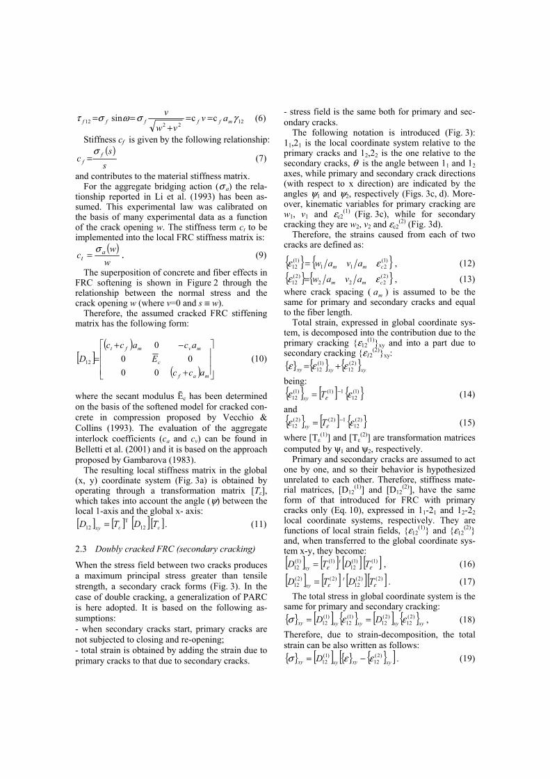
2.3 Doubly cracked FRC (secondary cracking)
When the stress field between two cracks produces a maximum principal stress greater than tensile strength, a secondary crack forms (Fig. 3). In the case of double cracking, a generalization of PARC is here adopted. It is based on the following as-sumptions: - when secondary cracks start, primary cracks are not subjected to closing and re-opening; - total strain is obtained by adding the strain due to primary cracks to that due to secondary cracks.
- stress field is the same both for primary and sec-ondary cracks.
The following notation is introduced (Fig. 3): 11,21 is the local coordinate system relative to the primary cracks and 12,22 is the one relative to the secondary cracks, θ is the angle between 11 and 12 axes, while primary and secondary crack directions (with respect to x direction) are indicated by the angles ψ1 and ψ2, respectively (Figs. 3c, d). More-over, kinematic variables for primary cracking are w1, v1 and εc2
(1) (Fig. 3c), while for secondary
cracking they are w2, v2 and εc2(2) (Fig. 3d).
Therefore, the strains caused from each of two cracks are defined as:
{ } { })1(211
)1(12 cmm avaw εε = , (12)
{ } { })2(222
)2(12 cmm avaw εε = , (13)
where crack spacing ( ma ) is assumed to be the same for primary and secondary cracks and equal to the fiber length.
Total strain, expressed in global coordinate sys-tem, is decomposed into the contribution due to the primary cracking {ε12
(1)}xy and into a part due to secondary cracking {ε12
(2)}xy: { } { } { }xyxyxy
)2(12
)1(12 εεε +=
being: { } [ ] { })1(
121)1()1(
12 εε ε−= Txy (14)
and { } [ ] { })2(
121)2()2(
12 εε ε−= Txy (15)
where [Tε(1)] and [Tε
(2)] are transformation matrices computed by ψ1 and ψ2, respectively.
Primary and secondary cracks are assumed to act one by one, and so their behavior is hypothesized unrelated to each other. Therefore, stiffness mate-rial matrices, [D12
(1)] and [D12(2)], have the same
form of that introduced for FRC with primary cracks only (Eq. 10), expressed in 11-21 and 12-22 local coordinate systems, respectively. They are functions of local strain fields, {ε12
(1)} and {ε12(2)}
and, when transferred to the global coordinate sys-tem x-y, they become: [ ] [ ] [ ] [ ])1()1(
12)1()1(
12 εε TDTD txy = , (16)
[ ] [ ] [ ][ ])2()2(12
)2()2(12 εε TDTD t
xy = . (17) The total stress in global coordinate system is the
same for primary and secondary cracking: { } [ ] { } [ ] { }xyxyxyxyxy DD )2(
12)2(
12)1(
12)1(
12 εεσ == , (18) Therefore, due to strain-decomposition, the total strain can be also written as follows: { } [ ] { } { }[ ]xyxyxyxy D )2(
12)1(
12 εεσ −= . (19)

0
1
2
3
4
5
6
7
0 0.05 0.1 0.2 0.25 0.3s ≡ w (mm)
0.15
( σ a+
σ f)
(MPa
)
Fibre bridging σs
Aggregate bridging σa
Fibre prestress σps
Total response
Figure 2. Aggregate and fiber roles in FRC softening (fc= 70 MPa, Vf = 2% , s≡w ).
l x
a)
σx
y τ yx τ xy
σy
τ σy
t x
σx
τ xy
yx
ly
b)
ψ121
12 ψ2
x
y
d)
c)
11
εc2(1)
ψ1 x 21
11 y
w1
v1
s1 ω1
εc2(2)
ψ222
12
w2
v2
s2ω2
x
y
am
am
22
Figure 3. (a) Doubly cracked element subjected to plane stress; (b) notations for primary and secondary cracking; (c) kinematic parameters of primary cracking; (d) kinematic parameters of secondary cracking.
Through simple analytical computations the stiffness matrix, which links stress to strain in global coordinate system for doubly cracked FRC, is formulated as follows: [ ] [ ] [ ]( [ ]( ([ ](
[ ] [ ] [ ] ) [ ] [ ] ))( )xyT
xyT
xyxyxy
DTTDT
DTDDD
)1(12
)2(11)2()1(
12)2(
)2(12
1)2()1(12
)1(12
−−−−
−
+
+−=
εεε
ε
(20)
3 EXPERIMENTAL MODEL
The behavior of SFRC slabs on grade was experi-mentally studied by performing tests on full-scale specimens having a square geometry with a side of 3 m and a thickness of 0.15 m (Fig. 4). The adopted dimensions are significant for industrial pavements, where the presence of construction joints can divide the structures into independent slabs.
Three different types of steel fibers have been adopted: hooked fibers having a length (lf) of 50 mm and a diameter (φf) of 1 mm (50/1.0, aspect ratio=50), hooked fibers lf=30 mm and φf=0.6 mm (30/0.6, aspect ratio=50), and straight fibers having lf=12 mm and φf = 0.18 mm (12/0.18, aspect ra-tio=67).
The slabs were made of a normal strength con-crete (C25/30) typical for pavement use. Table 1 shows the average values of compressive strength fc,cub (measured from cubes having a side of 150 mm), tensile strength fct and Young’s modulus of concrete Ec (both measured on cylinders with φ=80 mm and h=240 mm). These values were de-termined at the same day the slabs were tested. The volume fraction of fibers introduced in the experi-mental slabs is also shown in Table 1 (slab P0, the reference one, is made of plain concrete).
In order to determine the fracture properties of the materials adopted in the slab tests, four point bending tests have been performed on beams (150×150×600 mm), according to the Italian Stan-dard (UNI 2003). The bending tests were carried out by using a close loop hydraulic machine (In-stron) with the crack opening displacement as feedback control.
In order to reproduce a Winkler soil, the slabs were placed on small steel springs (Figs. 4a and 5) that were designed to simulate a typical Winkler constant (k=0.08 N/mm3) when they were placed at a distance of 375 mm in both directions. The springs were obtained through small steel plates supported along the border (Fig. 5). A thin layer of high-strength mortar was placed between the

springs and the slab to compensate for the out-of plane deformations of the concrete slab due to curl-ing (Fig. 5).
The stiffness of all these steel springs was ex-perimentally determined with several loading cy-cles. A typical result is shown in Figure 6. All the springs showed a similar behavior that was mod-eled by means of a bilinear curve.
The load was applied in the center of the slab by means of a hydraulic jack (Fig. 4b). A 1000 kN load cell was placed under the jack and 6 Linear Variable Differential Transformers (LVDTs) were used to measure the vertical displacements in dif-ferent locations of the slab (Fig. 4b).
Table 1. Mechanical properties of concrete and fiber content. _________________________________________ fc,cub ft Ec Vf Vf Vf Vf (MPa) (MPa) (MPa) % % % % SLAB 50/10 30/0.6 12/0.18 TOT _________________________________________ P0 35.9 2.7 21436 0 0 0 0 P1 35.3 2.7 24363 0 0.38 0 0.38 P2 33.9 2.7 28854 0 0.38 0.19 0.57 P3 33.9 2.7 29893 0.38 0 0.19 0.57 _________________________________________
(a)
(b)
Figure 4. (a) Spring position simulating the Winkler soil and (b) experimental setup.
Figure 5. Steel spring for simulating the elastic subgrade.
-14
-12
-10
-8
-6
-4
-2 0
2
-2.5
-1.5 -0.5
0.5 1.5 2.5
Vertical spring displacement (mm)
Load
(kN
)
Numerical curveExperimental curve
Figure 6. Spring stiffness
The experimental results underline the impor-tance of fiber reinforcement in concrete pavement (Fig. 7): Slab P0, without fibers, exhibit an ultimate load that is significantly lower than that obtained in the fiber reinforced slabs. In fact, in FRC slabs the load can still increase after the cracking due to the stress redistribution made possible by the material toughness and by the hyperstatic structure. More-over, the addition of short steel fibers (volume frac-tion equal to 0.19%) slightly increases the bearing capacity of Slabs P2 and P3. This can be seen as a synergism since small fibers may also reduce shrinkage cracking.

-50
0
50
100
150
200
250
300
0 2 4 6 8 10
Central displacement f (mm)
Loa
d (k
N)
P0
P1
P2
P3
Figure 7. Experimental load versus central displacement curves.
Figure 8. Multi-layered shell element mesh adopted.
4 NLFE ANALYSES AND COMPARISON WITH EXPERIMENTAL RESULTS
In order to better understand fracture behavior of SFRC slabs on grade and to investigate the reliabil-ity of the numerical model here proposed, the pre-viously presented experimental tests have been simulated by FE analyses. These analyses have been carried out by using multipurpose FE code ABAQUS (1999) where the material constitutive relationships were defined by user subroutines. Figure 8 shows the mesh of isoparametric multi-layered shell elements adopted. Layers describe the geometrical and mechanical features of shell cross section and behave as membrane elements sub-jected to plane stresses. The non-linear constitutive matrix of layers can be determined by means of PARC model.
In order to compute the stiffness matrix of the FE model, three Simpson’s integration points in each layer and Gaussian reduced integration on the mid-surface plane of shell element have been chosen. The non linear response of the springs, namely the no-tension behavior and the bilinear shape of the compression part, was taken into account by the numerical model as the trilinear law (Figure 6).
0
50
100
150
200
250
300
350
0 1 2 3 4 5 6Central displacement f (mm)
Loa
d (k
N)
Experimental
Proposed NLFEA
P0
0
50
100
150
200
250
300
350
0 1 2 3 4 5 6Central displacement f (mm)
Loa
d (k
N)
Experimental
Proposed NLFEA
P1
0
50
100
150
200
250
300
350
0 2 4 6 8 10Central displacement f (mm)
Loa
d (k
N)
Experimental
Proposed NLFEA
P2
0
50
100
150
200
250
300
350
0 2 4 6 8Central displacement f (mm)
Loa
d (k
N)
Experimental
Proposed NLFEA
P3
Figure 9. Total load versus central displacement for P0-P3 slabs: comparison between numerical and experimental results.

Figure 10. Crack pattern of P3 slab: primary cracks at (central displacement) f = 1.125mm (a), at f = 3mm (c) and at f = 7.5mm (d); secondary cracks at f = 1.125mm (b).
During numerical analyses the displacement of the slabs center has been monotonically increased, and the non-linear solution is reached by an itera-tive secant stiffness procedure based on the New-ton-Raphson convergence method.
Figure 9 shows a comparison between experi-mental and numerical results for the four experi-mental slabs, in terms of total applied load versus central displacement. The numerical model can well predict the experimental behavior both for plain (Slab P0) and fiber reinforced concrete slabs. In particular, the slab stiffness in the initial branch of the curves and the ultimate load can be evalu-ated with good precision. These quantities are the most important parameters for the slab design be-cause can predict the behavior of the structure at service limit state and at ultimate.
Another important parameter in slab design is the prediction of the final crack pattern since it evi-dences the collapse mechanism and allows other design methods (i.e. based on yield lines, Meda 2003) to be used. The numerical crack pattern at the bottom side of Slab P3 at different values of the central displacement (f) is presented in Figure 10. It can be noticed that a secondary crack appears when the principal stress due to bending is equal to the tensile strength (Fig. 10b). Figures 10a, d show the values of the crack opening displacement of primary and secondary cracks. One should observe that, by increasing the central displacements, the size of the doubly cracked zone does not increase significantly, but the continuous opening of secon-dary and primary cracks causes a loss of the slabs stiffness.
Figure 11 show the experimental crack pattern obtained for Slab P3. It can be noticed that, as pre-dicted in the numerical model (Fig. 10d), two main cracks develop along the median lines.
Figure 11. Slab P3: experimental crack pattern.
(a)
(b)
(c)
(d)
[mm]
[mm]
[mm]
[mm]

5 CONCLUDING REMARKS
Experimental tests have shown that steel-fiber rein-forcement significantly improves slab behavior in terms of strength, ductility and toughness. Fibers are efficient at both serviceability limit state, by reducing cracking phenomena due to loads or shrinkage effects, and at the ultimate limit state, by increasing the ultimate load.
Following the concept of strain-decomposition, the first version of PARC secant matrix has been improved by considering fixed primary and secon-dary cracks starting when maximum principal stress exceeds the tensile strength of concrete. The extension of PARC model to fiber reinforced con-crete under primary and secondary cracks stage has allowed a more realistic prediction of the nonlinear behavior of slabs on grade.
Both in the experimental tests and in the numeri-cal simulations, primary and secondary cracks were observed under service loads. For this reason, fixed-crack models considering only primary cracks results in stiffer response than experimental observations.
In order to better predict the behavior of FRC slabs on grade, adequate non linear numerical methods should be adopted. Contrarily to the elas-tic theory, methods based on non linear fracture mechanics take into account the stress redistribu-tion made possible by the material toughness and the hyperstatic structure (as the slab). These meth-ods can be used for a more accurate pavement de-sign.
REFERENCES
Bazant, Z. & Gambarova P. 1980. Rough cracks in reinforced concrete. Journal of Structural Division, Proceedings of ASCE, 106(4): 819-842.
Belletti B., Bernardi P., Cerioni R. & Iori I. 2003b. Non-linear analysis of reinforced concrete slabs. Proceedings of ISEC-02 Conference, 23-26 September 2003: : 663-668.
Belletti, B., Bernardi, P., Cerioni, R. & I. Iori 2002. On the role of fibers on the behaviour of FRC beams. Proceedings of XXXI National Symposium AIAS, Parma, Italy, 18-21 Sep-tember 2002.
Belletti, B., Bernardi, P., Cerioni, R. & Iori, I. 2003a. On a Fibre–Reinforced–Concrete Constitutive Model for NLFE Analysis. STUDIES AND RESEARCHES 24, Milan, Italy.
Belletti, B., Cerioni, R. & Iori, I. 2001. A physical approach for reinforced concrete (PARC) membrane elements. ASCE Journal of Structural Engineering 127(12): 1414-1426.
Darwin, D. & Pecknold, D.A. 1977. Non-linear biaxial stress-strain law for concrete. Proceedings of ASCE Journal of the Engineering Mechanics Division 103 (EM2): 229-241.
De Borst, R. & Nauta, P. 1985. Non-orthogonal cracks in a smeared finite element model. Engng. Computation 2: 35-46.
Gambarova, P. 1983. Sulla trasmissione del taglio in elementi bidimensionali piani di c.a. fessurati. Atti delle Giornate AI-CAP, Bari: 141-156.
ABAQUS 1999. Theory manual. Hibbitt, Karlsson & Sorensen, Pawtucket, R.I.
Hillerborg, A., Modèer, M. & Petersson, P.E. 1976. Analysis of crack formation and crack growth in concrete by means of fracture mechanics and finite elements. Cement and Concrete Research 6: 773-782.
Kupfer, H., Hilsdorf, H.K. & Rusch, H. 1969. Behavior of Con-crete Under Biaxial Stresses. Proceedings of ACI Journal 66(8): 656-666.
Li, V. C. 1992. Postcrack Scaling Relations for Fiber Rein-forced Cementitious Composites. Journal of Materials in Civil Engineering 4(1): 41-57.
Li, V.C. Stang, H. & Krenchel, H. 1993. Micromechanics of crack bridging in fiber-reinforced concrete. Materials and Structures 26: 486-494.
Meda, A. 2003. On the extension of the yield-line method to the design of SFRC slabs on grade. STUDIES AND RE-SEARCHES 24, Milan, Italy.
Meda, A. & Plizzari, G.A. 2003. A new design approach for SFRC slabs on grade based on fracture mechanics. ACI Structural Journal. In press
Riggs, H.R. & Powell, G.H. 1986. Rough crack model for analysis of concrete. J. Engng. Mech. ASCE, 112(5): 448-464.
Rots, J.G. & Blaauwendraad, J. 1989. Crack models for con-crete: discrete or smeared? Fixed, multi-directional or rotat-ing?. HERON 34(1): 1-59, The Netherlands.
UNI 11039. 2003. Steel fibre reinforced concrete - Part I: Defi-nitions, classification specification and conformity - Part II: test method for measuring first crack strength and ductility indexes. Italian Board for Standardization.
Vecchio, F.J. & Collins M.P. 1993. Compression Response of Cracked Reinforced Concrete. Journal of Structural Engi-neering, American Society of Civil Engineers 119(12): 3590-3610.
ACKNOWELEDGEMENTS
The experimental work was financed by Officine Maccaferri S.p.A. (Bologna, Italy). The under-standing and cooperation of Ing. Bruno Rossi (Pro-ject Supervisor) is kindly acknowledged.
The Authors would like to thank Dr. Luca Sorelli and Ing. Paolo Martinelli for their assistance in carrying out the experiments and Dr. Patrizia Ber-nardi and Ing. Martino Cerri for their assistance in running the numerical analyses.