experimental and computational assessment of a … · experimental and computational assessment of...
TRANSCRIPT

Experimental and Computational Assessment of a Ducted-FanRotor Flow Model
Ali Akturk∗ and Cengiz Camci†
Pennsylvania State University, University Park, Pennsylvania 16802
DOI: 10.2514/1.C031562
Ducted-fan-based vertical and/or short takeoff and landing uninhabited aerial vehicles are frequently
encountered in aeronautical applications. In edgewise flight, the performance of these vehicles is, in general, poor
because of the increasingly distorted inlet flow as the flight speed is increased. The present experimental study uses a
planar particle image velocimeter system to investigate the near duct aerodynamic performance in hover and
edgewise flight conditions. High-resolution particle image velocimetry measurements provide reliable and high-
resolution aerodynamic data forming a validation basis for further analytical and computational design studies. A
radial equilibrium-based fan aerodynamic model is also integrated into a three-dimensional Reynold-averaged-
Navier–Stokes-based computational system. Particle image velocimetry measurements and computational
predictions of the mean flow near the fan inlet plane are in very good agreement at hover conditions. The
aerodynamic modifications due to fan inlet flow distortion in an edgewise flight regime are clearly displayed in
particle image velocimetry results. A comparison of the current particle image velocimetry measurements and the
accelerated Reynold-averaged-Navier–Stokes predictions supported by the simple radial equilibrium-based rotor
model indicates that the current rotor model can be highly effective and time efficient in the design cycle of future
vertical and/or short takeoff and landing uninhabited aerial vehicle systems based on ducted fans.
Nomenclature
cx = axial velocityc� = tangential (swirl) velocity componentc1, c2 = rotor inlet and exit absolute velocityp = static pressureP0 = total pressurer = radial distance measured from originw1, w2 = rotor inlet and exit relative velocity�1, �2 = blade inlet and exit angle measured from axial
direction� = density� = rotational speed, rad=s
I. Introduction
D UCTED fans that are widely used propulsion systems invertical and/or short takeoff and landing (V/STOL) uninhabited
aerial vehicles (UAVs) offer a higher static thrust/power ratio for agiven diameter than open propellers. This is the result of diffusion ofthe propeller jet stream. They also provide impact protection for therotating blades and improve personnel safety due to the enclosed fanstructure as well as the lower noise level in the plane of the rotatingfan blade.
The viscous flow characteristics of the ducted fan are complex.These vehicles need to be capable of flight in a broad range ofatmospheric conditions, including the complex turbulent flowfieldsaround buildings and trees. When a V/STOL ducted fan is in
edgewise flight, because of the relative inlet flow dominantly parallelto its rotor inlet plane, flow separation at the leading-edge duct lip isencountered. The inlet flow separation leads to problems within theduct and may well result in a high pitchup moment as the edgewiseflight speed is increased. Excessive vibration in such systems is alsoreported. Therefore, measuring and predicting the three-dimensional(3-D) mean flow characteristics of ducted fans is crucial tounderstand the problems related to reliable and controllableedgewise flights. Numerous studies have been undertaken in order toquantify the flowfield properties in and around ducted fans. Theoperation of an axial flow fan with strong inlet flow distortionseverely affects the performance of the rotor especially near the tipregion of the blades.
Experimental investigation has been the major approach to studythe mean flow characteristics of the ducted fan. Abrego and Bulaga[1] performed wind-tunnel tests to determine the performancecharacteristics of ducted fans for axial and edgewise flight condi-tions. Their study resulted in showing the important effect of exitvane flap deflection and flap chord length on side force generation.Martin and Tung [2] tested a model ducted-fan V/STOLUAVwith a10-in.-diam fan rotor. They measured aerodynamic loads on thevehicle for different angles of attack in hover and different crosswindvelocities. They also included hot-wire velocity surveys at inner andouter surfaces of the duct and across the downstream wake,emphasizing the effect of tip gap on the thrust force produced. Inaddition, their study showed the effect of leading-edge radius of theduct on the stall performance and stability of the vehicle. Fleminget al. [3] conducted wind-tunnel experiments and computationalstudies around a 12-in.-diam ducted fan. They concentrated on theperformance of ducted-fan V/STOL vehicles in a crosswind.
Moreover, the ducted-fan design and performance analysis werewidely performed by using computational flowmodeling. Lind et al.[4] carried out a computational study using a panel method. Theycompared their results to the experimental results from Martin andTung [2]. Graf et al. [5] improved ducted-fan edgewise flightperformancewith a recently designed leading-edge geometry, whichwas a significant factor in offsetting the effects of the adverseaerodynamic characteristics. He and Xin [6] developed their ducted-fan models based on a nonuniform and unsteady ring-vortexformulation for the duct and blade element model for the fan.Numerical studies in axial flight and crosswind were conducted andvalidated against measured data. Chang and Rajagopalan [7]
Presented as Paper 2009-0332 at the 47th AIAA Aerospace SciencesMeeting , Orlando, FL, 5–8 January 2009; received 22 June 2011; revisionreceived 14 October 2011; accepted for publication 21 November 2011.Copyright © 2011 by Cengiz Camci and Ali Akturk. Published by theAmerican Institute of Aeronautics and Astronautics, Inc., with permission.Copies of this paper may be made for personal or internal use, on conditionthat the copier pay the $10.00 per-copy fee to theCopyright Clearance Center,Inc., 222RosewoodDrive, Danvers,MA01923; include the code 0021-8669/12 and $10.00 in correspondence with the CCC.
∗Postdoctoral Research Fellow, Turbomachinery Aero-Heat TransferLaboratory, Vertical Lift Research Center of Excellence, Department ofAerospace Engineering.
†Professor of Aerospace Engineering, Turbomachinery Aero-HeatTransfer Laboratory,Vertical Lift ResearchCenter of Excellence, Departmentof Aerospace Engineering.
JOURNAL OF AIRCRAFT
Vol. 49, No. 3, May–June 2012
885
Dow
nloa
ded
by P
EN
NSY
LV
AN
IA S
TA
TE
UN
IVE
RSI
TY
on
Oct
ober
16,
201
4 | h
ttp://
arc.
aiaa
.org
| D
OI:
10.
2514
/1.C
0315
62
developed an accurate grid generation methodology known as thecurve adaptive option to model several industrial ducted fans. Anaxisymmetric, incompressible Navier–Stokes solver was applied tocalculate the flowfield of a ducted fan. Their computational resultsagreed well with available wind-tunnel test data. Ahn and Lee [8]applied a computational method to their ducted-fan system toidentify the design parameters that affect its performance. Theirducted-fan system was designed by using a stream-surface-basedaxisymmetric analysis that provided the physical characteristics anddesign parameters of the system. Ko et al. [9] developed a computercode, aiming the preliminary design of a ducted-fan system. Thiscode was validated using data from many wind-tunnel and flighttests. Furthermore, it was extensively used in the design ofcommercial ducted fans. Recently, Zhao and Bil [10] proposed acomputational fluid dynamics (CFD) simulation to design andanalyze an aerodynamic model of a ducted-fan UAV in thepreliminary design phase with different speeds and angles of attack.
The current study uses a simultaneous experimental and compu-tational approach around a ducted fan that has a 5 in. diameter. Bythese analyses, a complicated flowfield around the ducted fan inhover and edgewise flight conditions is investigated. Flow featuressuch as inlet lip separation, distortion of inletflow features before andafter the axial fan rotor, influence of rotor tip speed, influence ofedgewiseflight velocity, and the interaction of the crosswindwith fanexit jet are investigated through experiments and computations. Forhigh-resolution mean flow experiments, a particle image velocimeter(PIV) is used. Axial and radial velocity components at the inlet/exitregion of the ducted fan are measured in hover and edgewise flight.By measuring axial and radial velocity components, the effect ofleading-edge duct lip separation on the flowfield into the fan rotor isquantified and analyzed.
For the current computational investigations, 3-D incompressibleReynolds-averaged Navier–Stokes (RANS) equations are solvedusing a general-purpose fluid mechanics solver, ANSYS FLUENT.To accelerate the viscous flow computations, a custom-developedrotor disk flow model based on the radial equilibrium equation, theenergy equation, and the conservation of angular momentumprinciple is integrated into the viscous flow solver. The specific radialequilibrium-theory-based fan-model implemented in this study usesa prescribed static pressure rise across the rotor disk for a timeefficient simulation of the fan rotor in the RANS computationalenvironment. The paper describes a method to compute the staticpressure rise at each radial position of the rotor blade in the functionof the rotor exit absolute velocity. A comparison of the current PIVmeasurements and the RANS predictions supported by the simpleradial equilibrium-based rotor model indicates that current compu-tational approaches can be highly effective and time efficient in thedesign of future V/STOL UAV systems based on ducted fans. Time-efficient and reasonably accurate rotor flowmodels developed in thisstudy are essential in the highly iterative design and optimizationcycles of ducted-fan-based V/STOL UAV systems.
II. Experimental Setup
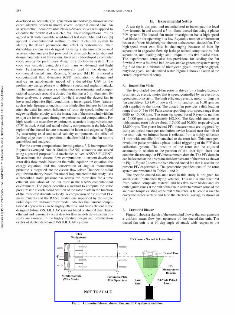
A test rig is designed and manufactured to investigate the localflow features in and around a 5-in.-diam. ducted fan using a planarPIV system. The ducted fan under investigation has a high-speedfive-bladed rotor operating in a low-Reynolds-number environmentbecause of short blade heights inherent to the current ducted fan. Thehigh-speed rotor exit flow is challenging because of inlet lipseparation in edgewise flow, tip leakage related complications, hubseparation, and leading-edge stall unique to this five-bladed rotor.The experimental setup also has provisions for seeding the fanflowfield with a fluidized bed-driven smoke-generator system usingfog fluid that is a mixture of triethylene glycol, propylene glycol,butylene glycol, and deionized water. Figure 1 shows a sketch of thecurrent experimental setup.
A. Ducted-Fan Model
The five-bladed ducted-fan rotor is driven by a high-efficiencybrushless dc electric motor that is speed-controlled by an electronicspeed control system. The high-efficiency electric motor driving thefan can deliver 1.5 kWof power (2.14 hp) and spin at 1050 rpm pervolt supplied to the motor. The ducted fan provides a disk loadingrange from 345 to 976 Pa in a corresponding rotor speed range from9000 to 15,000 rpm. The rotor tip speed-based Reynolds numberat 15,000 rpm is approximately 168,000. The Reynolds numbers atmidspan and rotor hub are about 115,000 and 70,000, respectively, at15,000 rpm. The phase-locked PIV measurements are triggered byusing an optical once-per-revolution device located near the hub ofthe rotor exit. An infrared beam is reflected from a highly reflective(1-mm-wide metallic film) attached to the rotor hub. This once-per-revolution pulse provides a phase-locked triggering of the PIV datacollection system. The position of the rotor can be adjustedaccurately in relation to the position of the laser light sheet thatcontains the rectangular PIVmeasurement domain. The PIV domaincan be located at the upstream and downstream of the rotor as shownin Fig. 1. Figure 2 shows the five-bladed ducted fan that is used in thepresent PIV experiments. The geometric specifications of the rotorsystem are presented in Tables 1 and 2.
The specific ducted-fan unit used in this study is designed forsmall-scale uninhabited flying vehicles. This unit is manufacturedfrom carbon composite material and has five rotor blades and sixoutlet guide vanes at the exit of the fan in order to remove some of theswirl and torque existing at the exit of the rotor. A tail cone is used tocover the motor surface and hide the electrical wiring, as shown inFig. 2.
B. Crosswind Blower
Figure 1 shows a sketch of the crosswind blower that can generatea uniform mean flow just upstream of the ducted-fan unit. Theducted-fan unit is at 90 deg angle of attack with respect to the
Fig. 1 Crosswind blower, ducted fan, and PIV system orientation.
886 AKTURK AND CAMCI
Dow
nloa
ded
by P
EN
NSY
LV
AN
IA S
TA
TE
UN
IVE
RSI
TY
on
Oct
ober
16,
201
4 | h
ttp://
arc.
aiaa
.org
| D
OI:
10.
2514
/1.C
0315
62

airstream generated by the cross-stream blower, as shown in Fig. 1.The axial flow fan driving the crosswind blower is capable ofgenerating 5:58 m3=s (10,594 cfm). There is a wire mesh screen justdownstream of the axial flow fan for turbulent flow managementpurposes. The flow passes through a 10-in.-wide flow straightenersection. Finally, there is a perforated plate (50% open area) at the exitof the crosswind blower. The grill, flow straightener, and perforatedplate at the exit provide a uniformmean flow at the exit of the system.The uniformity of the blower exit mean flow (6 m=s) is determinedby a hot-wire anemometer. The measured turbulence intensity of theuniform flow is about 0.9% based on the rms fluctuation velocityfluctuations normalized by the mean flow magnitude. An ac inverterconnected to the three-phase ac motor of the axial fan unit can adjustthe rotor revolutions per minute and mean flow velocity magnitudecoming out of the cross-stream blower.
III. Experimental Method
The planar PIV technique measures instantaneous velocitycomponents of a flowfield over a determined area in a planar lightsheet generated by a pulsed Nd:YAG laser. The general attributes ofthe specific planar PIV method are explained in detail in [11–16].Small particles existing in a fog generated by a fluidized bed systemare introduced into the fluid flow, and the region of interest isilluminated by a light sheet provided by short and multiple Nd:YAGlaser pulses lasting as short as a few nanoseconds. Nd:YAG laseremits visible green light at 532 nm after frequency doubling of theinfrared emission at 1064 nm originally produced at the laser cavity.The subsequent step is the recording of the displacement of particles
via one or two charge-coupled device (CCD) cameras, depending onthe specific PIV technique used. The four basic steps of a typicalplanar PIV measurement can be summarized as follows:
1) Flow is seeded.2) The flow region of interest is illuminated.3) Scattering light from the particles forming the speckle images is
recorded by a camera.4) Recordings are analyzed by means of a correlation-based
software system.In this current study, the inlet and exit mean flow performance of
the 5-in.-diam ducted fan was quantified by using the PIV technique.Axial and radial components of velocity profiles weremeasured nearthe inlet and exit planes of the ducted fan. Two separatemeasurementdomains of 156 � 96 mm are used in inlet and exit flows. Figure 1illustrates the PIV setup in which the fan exit field is measured bykeeping the PIV light sheet unchanged. For the measurement of inletflow velocities, the ducted fan is flipped vertically and rotated180 deg in a counterclockwise direction. The PIV measurementdomains are illuminated by a double-cavity frequency-doubledpulsating Nd:YAG laser that has a final emitted radiation wavelengthof 532 nm (green) and 120 mJ maximum pulse energy level. Pairs ofimages from measurement domains are captured by an 80C60HiSense PIV/planar laser-induced fluorescence PLIF camera. TheCCD camera is positioned normal to the laser sheet.
In planar PIV measurements, two components of the velocityvector are measured in the plane illuminated by a laser sheet. Thecurrent study focuses on measuring the axial and radial componentsof the local velocity vectors based on the imagemaps obtained by theCCD camera. The approximate size of the seeding particle is in arange between 0:25–60 �m. The image pairs of PIV domains arerecorded. The image maps are divided into 32 � 32 pixel inter-rogation areas, and 25% overlapping is used. The FlowMap softwareprovided by DANTEC [15] is used for capturing PIV images andcorrelation analysis. All 700 image pairs are adaptive correlated,moving average validated, and then ensemble averaged to obtain true
Fig. 2 Five-in.-diam five-bladed ducted fan.
Table 1 Geometric specifications of the
current ducted-fan rotor system
Parameter Value
Rotor hub diameter 52 mmRotor tip diameter 120 mmBlade height h 34 mmTip clearance t=h 5.8%Maximum blade thickness at rotor tip 1.5 mmTail cone diameter 52 mmTail cone length 105 mmRotor tip Re at 9000 rpm 100,000Rotor tip Re at 15,000 rpm 168,000
Table 2 Rotor blade section properties
Hub Midspan Tip
Blade inlet angle �1, deg 60 40 30Blade exit angle �2, deg 30 45 60Blade chord, mm 32 30 28
AKTURK AND CAMCI 887
Dow
nloa
ded
by P
EN
NSY
LV
AN
IA S
TA
TE
UN
IVE
RSI
TY
on
Oct
ober
16,
201
4 | h
ttp://
arc.
aiaa
.org
| D
OI:
10.
2514
/1.C
0315
62

mean flow. The ensemble size is of critical importance in achievingstatistically stable mean velocity distributions in any PIV datareduction process. Figures 3 and 4 present the influence of theensemble-averaging sample size on the spanwise distribution of themost significant velocity component that is the axial component.Both figures indicates that an ensemble size of 400 is sufficient inachieving a statistically stable average in the current set ofexperiments.
IV. Computational Method
A. Radial Equilibrium-Based Analysis of Ducted Fan in Hover
and Edgewise Flight
A computational simulation of the mean flowfield around theducted fan was performed by using the general-purpose fluidmechanics solver ANSYS FLUENT. The specific computationalsystem solves the 3-D RANS equations using a finite volumemethod. The transport equations describing the flowfield are solvedin the domain that is presently discretized by using an unstructuredcomputational mesh. A momentum equation and turbulence modelequations are discretized using a first-order upwind scheme, whilethe SIMPLE (semi-implicit method for pressure linked equations)algorithm was used for pressure–velocity coupling. For the analysisof the flowfield around ducted-fan rotors, there are many com-putational modeling options in general-purpose fluid dynamicssolvers. The most complex and time-consuming computationalmodel is the modeling of unsteady/viscous/turbulent flow in andaround the fan rotor by using an exact 3-D model of rotor geometryusing a sliding mesh technique. This type of solution including arotating frame of reference is usually lengthy and requires significantcomputer resources, especially in the edgewise flight mode when anaxisymmetric flow assumption is not applicable. The current RANScomputations use a custom-developed simplified rotor model,termed a “radial equilibrium-based actuator disk model,” for thegeneration of the general flow features of the fan rotor. Although therotor is modeled using an inviscid actuator disk, the flow areasoutside the rotor use a k-� turbulence model that was invoked for thecurrent computations. The 3-D RANS-based computational methodincluding the custom developed radial equilibrium-based actuatordisk is summarized in Fig. 5.
B. Boundary Conditions
1. Hover
Figure 6 shows the specific boundary conditions and computa-tional domain implemented in the solver for the hover condition. The
Fig. 3 Influence of ensemble averaging image sample size on the axial
velocity component.
Fig. 4 Influence of ensemble-averaging image sample size on the radial
velocity component.
Fig. 5 Flowchart of the 3-D RANS-based computational method including the actuator disk.
888 AKTURK AND CAMCI
Dow
nloa
ded
by P
EN
NSY
LV
AN
IA S
TA
TE
UN
IVE
RSI
TY
on
Oct
ober
16,
201
4 | h
ttp://
arc.
aiaa
.org
| D
OI:
10.
2514
/1.C
0315
62
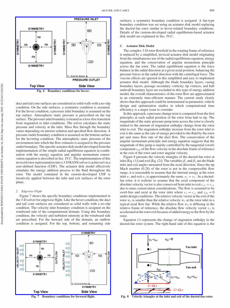
duct and tail cone surfaces are considered as solidwalls with a no-slipcondition. On the side surfaces, a symmetry condition is assumed.For the hover condition, a pressure inlet boundary is assumed on thetop surface. Atmospheric static pressure is prescribed on the topsurface. The pressure inlet boundary is treated as a loss-free transitionfrom stagnation to inlet conditions. The solver calculates the staticpressure and velocity at the inlet. Mass flux through the boundaryvaries depending on interior solution and specified flow direction. Apressure outlet boundary condition is assumed on the bottom surfacefor the hovering condition. The atmospheric static pressure of theenvironment into which the flow exhausts is assigned to the pressureoutlet boundary. The specific actuator diskmodel developed from theimplementation of the simple radial equilibrium equation in combi-nation with the energy equation and angular momentum conser-vation equation is described in Sec. IV.C. The implementation of thisinviscid rotor representation into a 3-DRANSsolver is achievedvia auser-defined function (UDF). The actuator disk model effectivelysimulates the energy addition process to the fluid throughout therotor. The model contained in the custom-developed UDF isiteratively applied between the inlet and exit surfaces of the rotorplane.
2. Edgewise Flight
Figure 7 shows the specific boundary conditions implemented inthe 3-D solver for edgewise flight. Like the hover condition, the ductand tail cone surfaces are considered as solid walls with a no-slipcondition. The velocity inlet boundary condition is assigned on thewindward side of the computational domain. Using this boundarycondition, the velocity and turbulent intensity at the windward sideare prescribed. For the leeward side of the domain, an outflowcondition is assigned. For the top, bottom, and remaining side
surfaces, a symmetry boundary condition is assigned. A fan-typeboundary condition was set using an actuator disk model replacingthe ducted-fan rotor similar to hover-related boundary conditions.Details of the custom-developed radial equilibrium-based actuatordisk model are explained in Sec. IV.C.
C. Actuator Disk Model
The complex 3-D rotor flowfield in the rotating frame of referenceis replaced by a simplified, inviscid actuator disk model originatingfrom the simultaneous use of the radial equilibrium equation, energyequation, and the conservation of angular momentum principleacross the fan rotor. The radial equilibrium equation is the forcebalance in the radial direction at a given axial position, balancing thepressure forces in the radial direction with the centrifugal force. Theviscous effects are ignored in this simplified and easy to implementactuator disk model. Although the blade boundary layers, casingboundary layers, passage secondary vorticity, tip vortices, and hubendwall boundary layer are excluded in this type of energy additionmodel, the overall characteristics of the rotor flow are approximatedin an extremely time-efficient manner. The current study clearlyshows that this approach could be instrumental in parametric vehicledesign and optimization studies in which computational timeefficiency is a major issue to consider.
In this approach, a pressure change term is computed from the firstprinciples at each radial position of the rotor from hub to tip. Themagnitude of the static pressure jump term across the rotor is closelyrelated to the amount of stagnation enthalpy change from the rotorinlet to exit. The stagnation enthalpy increase from the rotor inlet toexit is the same as the rate of energy provided to the fluid by the rotorper unit mass flow rate of the duct flow. The conservation of theangular momentum principle and energy equation suggests that themagnitude of this jump is mainly controlled by the tangential (swirl)component c�2 of the flow velocity in the absolute frame of referenceat the exit of the rotor and rotor angular velocity.
Figure 8 presents the velocity triangles of the ducted-fan rotor atinlet [Eq. (1)] and exit [Eq. (2)]. The variables�1 and�2 are the bladeinlet and exit angles measured from the axial direction. Since the tipMach number (0.28) of the rotor is not in the compressible flowrange, it is reasonable to assume that the internal energy at the rotorinlet e1 and exit e2 is approximately the same, e1 � e2 . In a ducted-fan rotor, it is realistic to assume that the axial component of theabsolute velocity vector is also conserved from inlet to exit cx2 � cx1due to mass conservation considerations. The flow is assumed to beswirl-free and axial at the rotor inlet where c1 � cx1 and c�1 � 0under design conditions. The relative velocity vector at the exit of therotor w2 is smaller than the relative velocity w1 at the rotor inlet in atypical axial flow fan. While the relative flow w2 is diffusing in therelative frame of reference, the absolute flow velocity vector c2 isaccelerated at the rotor exit because of added energy to theflowby therotor.
Equation (1) represents the change of stagnation enthalpy in theducted-fan rotor system. The right-hand side of this equation is the
Fig. 6 Boundary conditions for hover.
Fig. 7 Boundary conditions for forward flight. Fig. 8 Velocity triangles at the inlet and exit of the ducted-fan rotor.
AKTURK AND CAMCI 889
Dow
nloa
ded
by P
EN
NSY
LV
AN
IA S
TA
TE
UN
IVE
RSI
TY
on
Oct
ober
16,
201
4 | h
ttp://
arc.
aiaa
.org
| D
OI:
10.
2514
/1.C
0315
62

rate of work per unit mass flow rate of air passing from the rotor.The right-hand side is also the same as the product of the rotor torqueand angular speed of the fan rotor:
hO2 � hO1 �U�c�2 � c�1� (1)
where
U��r and c�1 � 0
�h2 � c22=2� � �h1 � c21=2� �Uc�2 (2)
�e2 �
p2
�2� c22=2
���e1 �
p1
�1� c21=2
��Uc�2 (3)
Equation (1) is a simplified form of the energy equation andangular momentum conservation (combined) expressed from rotor
Fig. 9 Streamlines at the inlet and exit of a ducted fan for a) hover and b) edgewise flight (PIV measurements at 9000 rpm).
Fig. 10 Streamlines at the inlet and exit of a ducted fan for a) hover and b) edgewise flight (PIV measurements at 15,000 rpm).
890 AKTURK AND CAMCI
Dow
nloa
ded
by P
EN
NSY
LV
AN
IA S
TA
TE
UN
IVE
RSI
TY
on
Oct
ober
16,
201
4 | h
ttp://
arc.
aiaa
.org
| D
OI:
10.
2514
/1.C
0315
62

inlet to exit of a ducted-fan unit. When e1 � e2 is substituted intoEq. (3) because of the incompressibility condition, theEuler equationor pump equation results in Eq. (4). Using Eqs. (4) and (5), anequation for the calculation of the static pressure jump between therotor inlet and exit can be obtained.
The determination of c�2 is performed by using the velocitytriangles as shown in Fig. 8. Since the blade inlet/exit angledistribution for “1” and “2” in the radial direction is known from theexisting rotor geometrical properties (shown in Tables 1 and 2), w2
can be calculated from the assumption that cx2 � cx1 � c1. Theabsolute rotor exit velocity c2 is determined by addingU��r tow2
in a vectorial sense:
1� �PO2 � PO1� �Uc�2 (4)
Equation (4) could be rearranged as follows:
�p2 � �
c222
���p1 � �
c212
�� �Uc�2 (5)
By expressing (p2 � p1) from Eq. (5), a pressure jump statementin the function of radius could be obtained:
�p� p2 � p1 � ��Uc�2 � 12�c22 � c21�� (6)
Equation (6) allows the enforcing of a prescribed pressure jump pin the function of density, radial position, rotor angular speed�, rotorexit swirl velocity c�2, c1, and c2. The rate of energy per unit massflow rate added to the flow by the rotor is specified by the productUc�2, as shown in Eqs. (4) and (5). Equation (6) could be evaluated ateach radial position between the rotor hub and tip, resulting in theradial distribution of the static pressure jump required by the general-purpose viscous flow solver for a so-called fan-type boundarycondition. �p can be effectively specified in a UDF in the general-purpose solver. The fan-type boundary condition is an effective andtime-efficient method of implementing a rotor flowfield via a radialequilibrium-based actuator disk model in a 3-D viscous flowcomputation.
V. Experimental Results in Hover and EdgewiseFlight Conditions
Experiments were performed at two different rotational speeds at9000 and 15,000 rpm. The overall performance of the ducted fan wasmeasured and analyzed in hover and edgewise flight conditions. Theedgewiseflight condition is simulated in laboratory experimentswitha crosswind of 6 m=s velocity produced by the crosswind blower, asshown in Fig. 1. The ratios of edgewise flight velocity and axialvelocity at midspan is calculated as 0.46 and 0.27 for 9000 and15,000 rpm, respectively.
Figures 9a and 10a show streamlines obtained from PIVmeasurements at different rotational speeds (9000 and 15,000 rpm)in hovering. The figures are contour plotted and colored with themagnitude of measured velocity. As expected, the magnitude ofvelocity is increasing at both inlet and exit regions by increasing therotational speed of the fan rotor. The streamline structure and thelocal magnitude of the velocity vector show a reasonable axisym-metry in hover mode, as shown in Figs. 9a and 10a. The exit jet from
Fig. 11 Axial velocity distribution at the inlet and exit of a ducted fan at
9000 and 15,000 rpm.
Fig. 12 Velocity components at the hover condition (PIV measurements at 9000 rpm): a) axial and b) radial.
AKTURK AND CAMCI 891
Dow
nloa
ded
by P
EN
NSY
LV
AN
IA S
TA
TE
UN
IVE
RSI
TY
on
Oct
ober
16,
201
4 | h
ttp://
arc.
aiaa
.org
| D
OI:
10.
2514
/1.C
0315
62
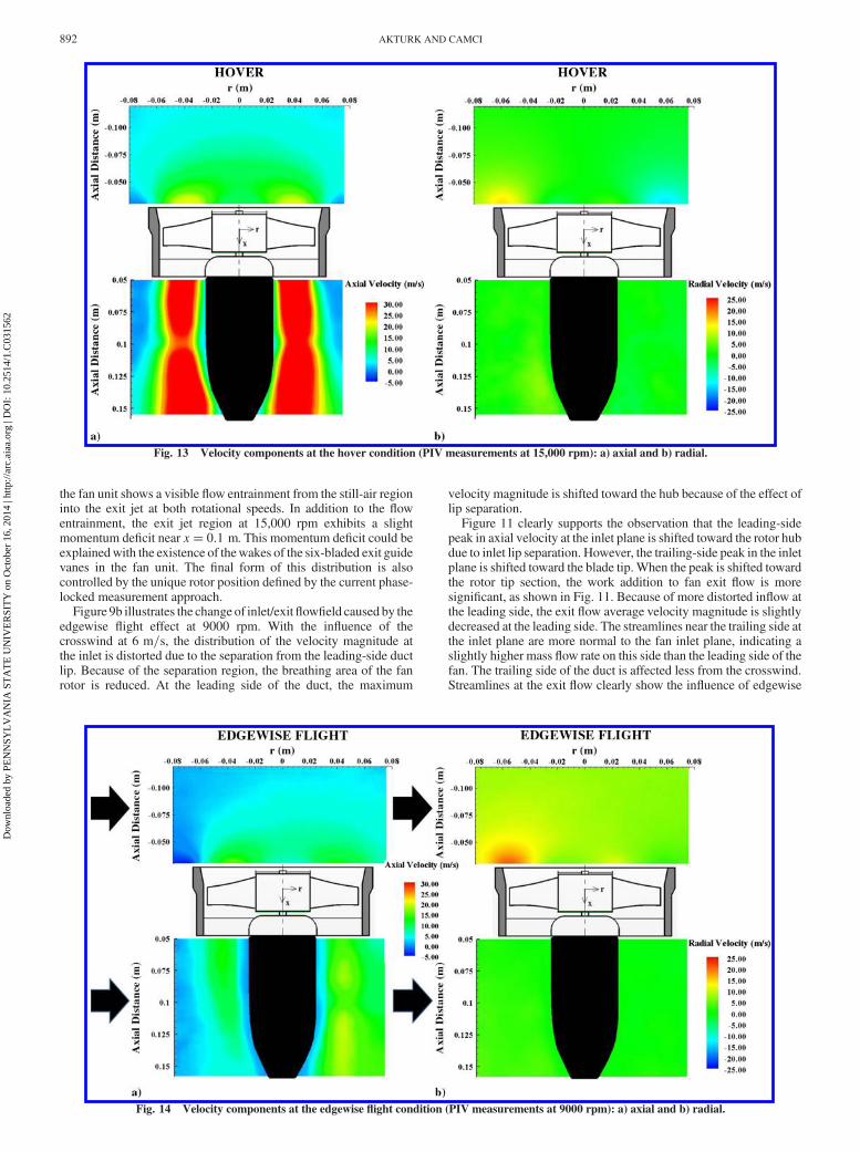
the fan unit shows a visible flow entrainment from the still-air regioninto the exit jet at both rotational speeds. In addition to the flowentrainment, the exit jet region at 15,000 rpm exhibits a slightmomentum deficit near x� 0:1 m. This momentum deficit could beexplainedwith the existence of thewakes of the six-bladed exit guidevanes in the fan unit. The final form of this distribution is alsocontrolled by the unique rotor position defined by the current phase-locked measurement approach.
Figure 9b illustrates the change of inlet/exitflowfield caused by theedgewise flight effect at 9000 rpm. With the influence of thecrosswind at 6 m=s, the distribution of the velocity magnitude atthe inlet is distorted due to the separation from the leading-side ductlip. Because of the separation region, the breathing area of the fanrotor is reduced. At the leading side of the duct, the maximum
velocity magnitude is shifted toward the hub because of the effect oflip separation.
Figure 11 clearly supports the observation that the leading-sidepeak in axial velocity at the inlet plane is shifted toward the rotor hubdue to inlet lip separation. However, the trailing-side peak in the inletplane is shifted toward the blade tip. When the peak is shifted towardthe rotor tip section, the work addition to fan exit flow is moresignificant, as shown in Fig. 11. Because of more distorted inflow atthe leading side, the exit flow average velocity magnitude is slightlydecreased at the leading side. The streamlines near the trailing side atthe inlet plane are more normal to the fan inlet plane, indicating aslightly higher mass flow rate on this side than the leading side of thefan. The trailing side of the duct is affected less from the crosswind.Streamlines at the exit flow clearly show the influence of edgewise
Fig. 13 Velocity components at the hover condition (PIV measurements at 15,000 rpm): a) axial and b) radial.
Fig. 14 Velocity components at the edgewise flight condition (PIV measurements at 9000 rpm): a) axial and b) radial.
892 AKTURK AND CAMCI
Dow
nloa
ded
by P
EN
NSY
LV
AN
IA S
TA
TE
UN
IVE
RSI
TY
on
Oct
ober
16,
201
4 | h
ttp://
arc.
aiaa
.org
| D
OI:
10.
2514
/1.C
0315
62
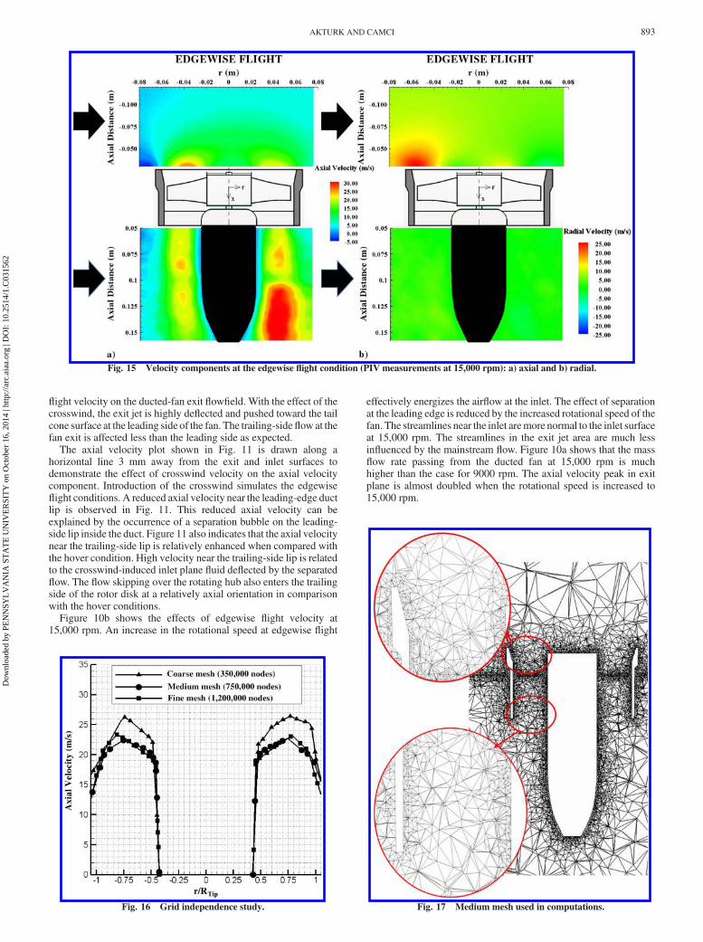
flight velocity on the ducted-fan exit flowfield. With the effect of thecrosswind, the exit jet is highly deflected and pushed toward the tailcone surface at the leading side of the fan. The trailing-side flow at thefan exit is affected less than the leading side as expected.
The axial velocity plot shown in Fig. 11 is drawn along ahorizontal line 3 mm away from the exit and inlet surfaces todemonstrate the effect of crosswind velocity on the axial velocitycomponent. Introduction of the crosswind simulates the edgewiseflight conditions. A reduced axial velocity near the leading-edge ductlip is observed in Fig. 11. This reduced axial velocity can beexplained by the occurrence of a separation bubble on the leading-side lip inside the duct. Figure 11 also indicates that the axial velocitynear the trailing-side lip is relatively enhanced when compared withthe hover condition. High velocity near the trailing-side lip is relatedto the crosswind-induced inlet plane fluid deflected by the separatedflow. The flow skipping over the rotating hub also enters the trailingside of the rotor disk at a relatively axial orientation in comparisonwith the hover conditions.
Figure 10b shows the effects of edgewise flight velocity at15,000 rpm. An increase in the rotational speed at edgewise flight
effectively energizes the airflow at the inlet. The effect of separationat the leading edge is reduced by the increased rotational speed of thefan. The streamlines near the inlet aremore normal to the inlet surfaceat 15,000 rpm. The streamlines in the exit jet area are much lessinfluenced by the mainstream flow. Figure 10a shows that the massflow rate passing from the ducted fan at 15,000 rpm is muchhigher than the case for 9000 rpm. The axial velocity peak in exitplane is almost doubled when the rotational speed is increased to15,000 rpm.
Fig. 15 Velocity components at the edgewise flight condition (PIV measurements at 15,000 rpm): a) axial and b) radial.
Fig. 16 Grid independence study. Fig. 17 Medium mesh used in computations.
AKTURK AND CAMCI 893
Dow
nloa
ded
by P
EN
NSY
LV
AN
IA S
TA
TE
UN
IVE
RSI
TY
on
Oct
ober
16,
201
4 | h
ttp://
arc.
aiaa
.org
| D
OI:
10.
2514
/1.C
0315
62

Figures 12 and 13 illustrate the axial and radial velocitycomponents at 9000 and 15,000 rpm for the hover condition. Anincrease in axial velocity by a rotational speed increase results in asignificant enhancement of the axial momentum of the system. Theradial velocities that are usually inmuch smaller magnitudes than theaxial components show a symmetrical distribution with respect tothe axis of rotation. The axial and radial velocity components in thehover condition results in a reasonably uniform distribution of sideforces around the duct.
Introducing a crosswind velocity to the field changes thedistribution of radial flow velocity around the duct. Figures 14b and15b indicate an abrupt increase near the leading side of the duct lip.That increase in radial velocity is the result of the strong recirculatoryflow near the leading side, as expected. The flow nonuniformitiesnear the leading side of the lip and the strong variations between theleading and the trailing sides of the exit jet result in a strong pitchupmoment acting on the ducted fan. It is also observed that, by theincrease of rotational speed, the radial velocity is also increasing. Butthe same amount of increase can also be seen on the radial velocitydistribution in the hovering mode. When the rotational speed isincreased, the axial momentum of the flow is increased.
VI. Computational Results
A. Grid Refinement Study
A grid independence study was performed to show that thecomputational results are not dependent on the computational meshand that the resolution of the mesh is adequate to capture thesignificant flow characteristics. The grid independency is evaluatedby comparing the computational solutions from three different meshsizes comprising a coarse mesh with 350,000 nodes, a mediummeshwith 750,000 nodes, and a finemeshwith 1,200,000 nodes. The axialvelocity distributions at the exit of the ducted fan are plotted as shownin Fig. 16 for three different grid densities. The profiles suggest thatthe computational results are grid independentwhen the 750,000 gridnode number is exceeded. Therefore, themediummesh is used for allpredictions in this investigation. Figure 17 shows a view from themesh used in the current computations.
B. Model Validation at Hover and Edgewise Flight
1. Hover Condition Results
In this section, the results of 3-D computations using the customradial equilibrium-based rotor diskmodel are comparedwith the PIV
Fig. 18 Comparison of the axial velocity at the fan inlet 3 mm away from the duct surface at a hover condition of 9000 rpm.
Fig. 19 Comparison of the axial velocity at a fan exit 3 mm away from the duct surface at a hover condition of 9000 rpm.
894 AKTURK AND CAMCI
Dow
nloa
ded
by P
EN
NSY
LV
AN
IA S
TA
TE
UN
IVE
RSI
TY
on
Oct
ober
16,
201
4 | h
ttp://
arc.
aiaa
.org
| D
OI:
10.
2514
/1.C
0315
62

experiments performed for the 5-in.-diam ducted fan. The computedaxial velocity component 3 mm away from the duct inlet surface iscompared with the results of PIVmeasurements, as shown in Fig. 18.The computational and experimental results are in good agreementnear the leading side of the fan at the inlet plane. The computationalpredictions near the leading side and the trailing side show an almostsymmetrical axial velocity distribution.
The simulation underpredicts the flow as measured by PIV nearthe trailing side of the duct, as shown in Fig. 18. In a phase-lockedPIV approach, measurements are always performed at the samecircumferential position of the rotor blade. Since we used a five-bladed fan rotor, the right side of the domain in Fig. 18 contains arotor blade in the laser sheet. However, the left side of the domain,where r 0, does not contain a rotor blade in the laser sheet. Theslight underprediction is related to the specific phase-locked positionof the rotor during the PIV measurements. Because of the blockageeffect introduced by the rotor blade in the laser sheet plane, the PIV
measured axial flow velocity magnitude is slightly altered whencompared with the computational result.
The comparison of PIV measurements and computed axialvelocity components 3 mm away from the duct exit surface areshown in Fig. 19. Since the computational method does not take tiplosses, casing boundary layers and secondary flows into account,there is an overprediction of axial velocity near the casing of theducted fan. It can also be observed that the rotating rotor hub relatedlosses are not predicted well by the current computations.
Figure 20 shows comparison of contour plots obtained from thecomputational predictions and PIV measurements. Computationalresults are slightly overpredicting the measured axial velocity at theinlet of the ducted fan. In addition, predictions near the hub arelower than the measurements because the rotating hub is notsimulated in the computations. The hub separation usually exists ina small diameter of ducted-fan rotors where the near-hub regionexhibits a very complex relatively low-Reynolds-number flow with
Fig. 20 Comparison of CFD and PIV axial velocity contours at a hover condition of 9000 rpm.
Fig. 21 Comparison of CFD and PIV axial velocity contours at an edgewise flight of 9000 rpm and 6 m=s.
AKTURK AND CAMCI 895
Dow
nloa
ded
by P
EN
NSY
LV
AN
IA S
TA
TE
UN
IVE
RSI
TY
on
Oct
ober
16,
201
4 | h
ttp://
arc.
aiaa
.org
| D
OI:
10.
2514
/1.C
0315
62
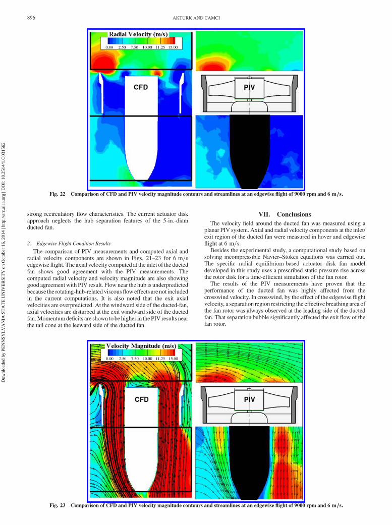
strong recirculatory flow characteristics. The current actuator diskapproach neglects the hub separation features of the 5-in.-diamducted fan.
2. Edgewise Flight Condition Results
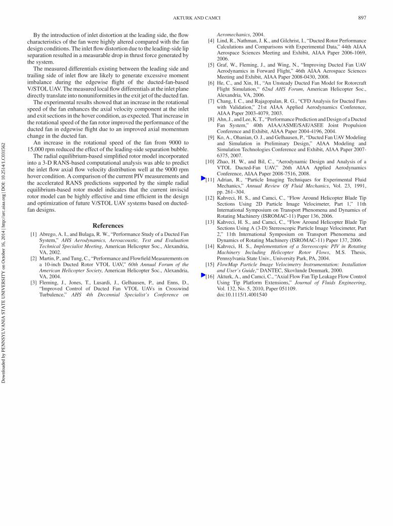
The comparison of PIV measurements and computed axial andradial velocity components are shown in Figs. 21–23 for 6 m=sedgewiseflight. The axial velocity computed at the inlet of the ductedfan shows good agreement with the PIV measurements. Thecomputed radial velocity and velocity magnitude are also showinggood agreement with PIV result. Flow near the hub is underpredictedbecause the rotating-hub-related viscousfloweffects are not includedin the current computations. It is also noted that the exit axialvelocities are overpredicted. At the windward side of the ducted-fan,axial velocities are disturbed at the exit windward side of the ductedfan.Momentumdeficits are shown to be higher in the PIV results nearthe tail cone at the leeward side of the ducted fan.
VII. Conclusions
The velocity field around the ducted fan was measured using aplanar PIV system. Axial and radial velocity components at the inlet/exit region of the ducted fan were measured in hover and edgewiseflight at 6 m=s.
Besides the experimental study, a computational study based onsolving incompressible Navier–Stokes equations was carried out.The specific radial equilibrium-based actuator disk fan modeldeveloped in this study uses a prescribed static pressure rise acrossthe rotor disk for a time-efficient simulation of the fan rotor.
The results of the PIV measurements have proven that theperformance of the ducted fan was highly affected from thecrosswind velocity. In crosswind, by the effect of the edgewise flightvelocity, a separation region restricting the effective breathing area ofthe fan rotor was always observed at the leading side of the ductedfan. That separation bubble significantly affected the exit flow of thefan rotor.
Fig. 22 Comparison of CFD and PIV velocity magnitude contours and streamlines at an edgewise flight of 9000 rpm and 6 m=s.
Fig. 23 Comparison of CFD and PIV velocity magnitude contours and streamlines at an edgewise flight of 9000 rpm and 6 m=s.
896 AKTURK AND CAMCI
Dow
nloa
ded
by P
EN
NSY
LV
AN
IA S
TA
TE
UN
IVE
RSI
TY
on
Oct
ober
16,
201
4 | h
ttp://
arc.
aiaa
.org
| D
OI:
10.
2514
/1.C
0315
62
By the introduction of inlet distortion at the leading side, the flowcharacteristics of the fan were highly altered compared with the fandesign conditions. The inletflowdistortion due to the leading-side lipseparation resulted in a measurable drop in thrust force generated bythe system.
The measured differentials existing between the leading side andtrailing side of inlet flow are likely to generate excessive momentimbalance during the edgewise flight of the ducted-fan-basedV/STOLUAV.Themeasured localflowdifferentials at the inlet planedirectly translate into nonuniformities in the exit jet of the ducted fan.
The experimental results showed that an increase in the rotationalspeed of the fan enhances the axial velocity component at the inletand exit sections in the hover condition, as expected. That increase inthe rotational speed of the fan rotor improved the performance of theducted fan in edgewise flight due to an improved axial momentumchange in the ducted fan.
An increase in the rotational speed of the fan from 9000 to15,000 rpm reduced the effect of the leading-side separation bubble.
The radial equilibrium-based simplified rotor model incorporatedinto a 3-D RANS-based computational analysis was able to predictthe inlet flow axial flow velocity distribution well at the 9000 rpmhover condition. A comparison of the current PIVmeasurements andthe accelerated RANS predictions supported by the simple radialequilibrium-based rotor model indicates that the current inviscidrotor model can be highly effective and time efficient in the designand optimization of future V/STOL UAV systems based on ducted-fan designs.
References
[1] Abrego, A. I., and Bulaga, R. W., “Performance Study of a Ducted FanSystem,” AHS Aerodynamics, Aeroacoustic, Test and Evaluation
Technical Specialist Meeting, American Helicopter Soc., Alexandria,VA, 2002.
[2] Martin, P., and Tung, C., “Performance and FlowfieldMeasurements ona 10-inch Ducted Rotor VTOL UAV,” 60th Annual Forum of the
American Helicopter Society, American Helicopter Soc., Alexandria,VA, 2004.
[3] Fleming, J., Jones, T., Lusardi, J., Gelhausen, P., and Enns, D.,“Improved Control of Ducted Fan VTOL UAVs in CrosswindTurbulence,” AHS 4th Decennial Specialist’s Conference on
Aeromechanics, 2004.[4] Lind, R., Nathman, J. K., and Gilchrist, I., “Ducted Rotor Performance
Calculations and Comparisons with Experimental Data,” 44th AIAAAerospace Sciences Meeting and Exhibit, AIAA Paper 2006-1069,2006.
[5] Graf, W., Fleming, J., and Wing, N., “Improving Ducted Fan UAVAerodynamics in Forward Flight,” 46th AIAA Aerospace SciencesMeeting and Exhibit, AIAA Paper 2008-0430, 2008.
[6] He, C., and Xin, H., “An Unsteady Ducted Fan Model for RotorcraftFlight Simulation,“ 62nd AHS Forum, American Helicopter Soc.,Alexandria, VA, 2006.
[7] Chang, I. C., and Rajagopalan, R. G., “CFD Analysis for Ducted Fanswith Validation,” 21st AIAA Applied Aerodynamics Conference,AIAA Paper 2003-4079, 2003.
[8] Ahn, J., andLee,K. T., “Performance Prediction andDesign of aDuctedFan System,” 40th AIAA/ASME/SAE/ASEE Joint PropulsionConference and Exhibit, AIAA Paper 2004-4196, 2004.
[9] Ko, A., Ohanian, O. J., and Gelhausen, P., “Ducted Fan UAVModelingand Simulation in Preliminary Design,” AIAA Modeling andSimulation Technologies Conference and Exhibit, AIAA Paper 2007-6375, 2007.
[10] Zhao, H. W., and Bil, C., “Aerodynamic Design and Analysis of aVTOL Ducted-Fan UAV,” 26th AIAA Applied AerodynamicsConference, AIAA Paper 2008-7516, 2008.
[11] Adrian, R., “Particle Imaging Techniques for Experimental FluidMechanics,” Annual Review Of Fluid Mechanics, Vol. 23, 1991,pp. 261–304.
[12] Kahveci, H. S., and Camci, C., “Flow Around Helicopter Blade TipSections Using 2D Particle Image Velocimeter, Part 1,” 11thInternational Symposium on Transport Phenomena and Dynamics ofRotating Machinery (ISROMAC-11) Paper 136, 2006.
[13] Kahveci, H. S., and Camci, C., “Flow Around Helicopter Blade TipSections Using A (3-D) Stereoscopic Particle Image Velocimeter, Part2,” 11th International Symposium on Transport Phenomena andDynamics of Rotating Machinery (ISROMAC-11) Paper 137, 2006.
[14] Kahveci, H. S., Implementation of a Stereoscopic PIV in Rotating
Machinery Including Helicopter Rotor Flows, M.S. Thesis,Pennsylvania State Univ., University Park, PA, 2004.
[15] FlowMap Particle Image Velocimetry Instrumentation: Installation
and User’s Guide,“ DANTEC, Skovlunde Denmark, 2000.[16] Akturk, A., and Camci, C., “Axial Flow Fan Tip Leakage Flow Control
Using Tip Platform Extensions,” Journal of Fluids Engineering,Vol. 132, No. 5, 2010, Paper 051109.doi:10.1115/1.4001540
AKTURK AND CAMCI 897
Dow
nloa
ded
by P
EN
NSY
LV
AN
IA S
TA
TE
UN
IVE
RSI
TY
on
Oct
ober
16,
201
4 | h
ttp://
arc.
aiaa
.org
| D
OI:
10.
2514
/1.C
0315
62