blade dynamic stress analysis of rotating bladed disks€¦ · blade dynamic stress analysis of...
TRANSCRIPT
Blade dynamic stress analysis of rotating bladed disksJ. Kellnera,∗, V. Zemana
aFaculty of Applied Sciences, UWB in Pilsen, Univerzitnı 22, 306 14 Plzen, Czech Republic
Received 10 September 2007; received in revised form 24 September 2007
Abstract
The paper deals with mathematical modelling of steady forced bladed disk vibrations and with dynamic stresscalculation of the blades. The blades are considered as 1D kontinuum elastic coupled with three-dimensional elasticdisk centrally clamped into rotor rotating with constant angular speed. The steady forced vibrations are generatedby the aerodynamic forces acting along the blade length. By using modal synthesis method the mathematical modelof the rotating bladed disk is condensed to calculate steady vibrations. Dynamic stress analysis of the blades isbased on calculation of the time dependent reduced stress in blade cross-sections by using Hubert-Misses-Henckystress hypothesis. The presented method is applied to real turbomachinery rotor with blades connected on the topwith shroud.c©2007 University of West Bohemia. All rights reserved.
Keywords: rotating disk, stress analysis, forced vibration
1. Introduction
The rotating systems are often modelled as one-dimensional rotating bodies with rigid disksattached to them [3], [7], [8]. Previously created model of the rotating bladed disk [9] hasbeen applied for bladed disk forced vibration [2]. Using real disk properties and excitation byaerodynamic forces [4] there is determined dynamic behaviour of individual blades as well asof the disk. For blade dynamic stress analysis and successive high-cyclic fatigue failures thereis the need to transform the forced vibration into stress response. The aim of this article is todevelop an original method for stress analysis in different locations of the arbitrary blade using3D modelling of the disk [5], 1D modelling of the blades [1] and reduction of number of bladeddisk DOF by modal synthesis method.
2. Mathematical model of the rotating bladed disk
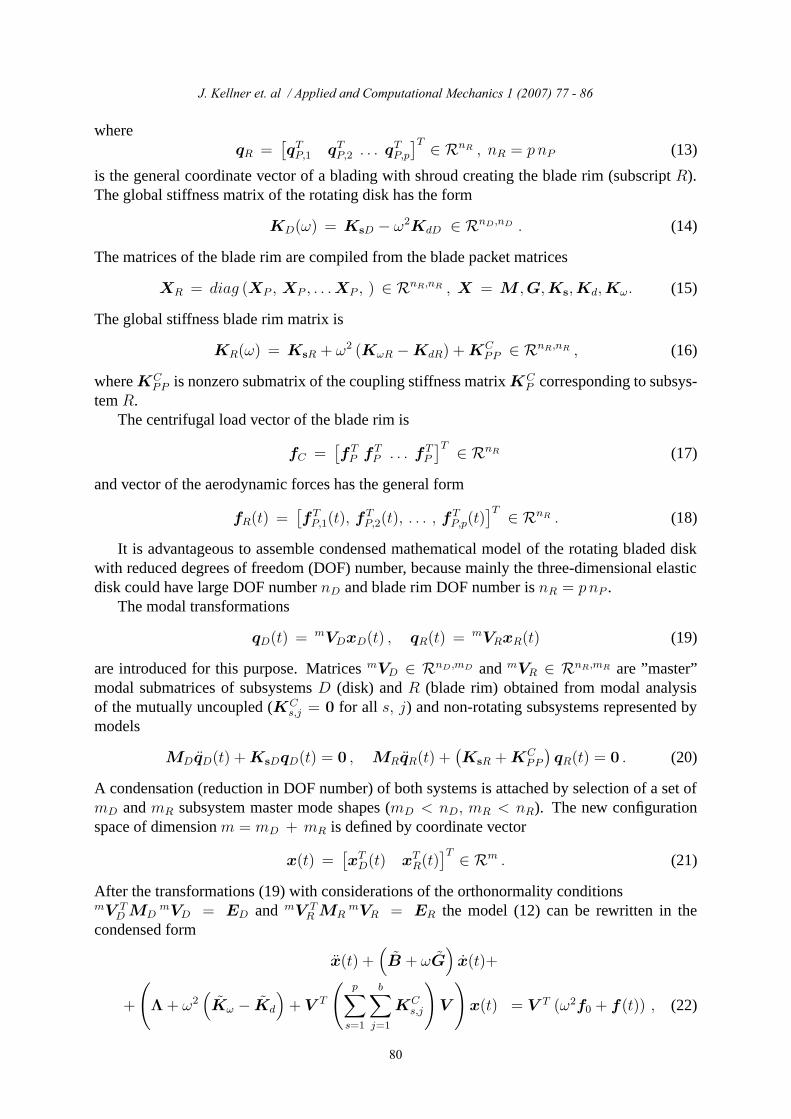
The rotating bladed disk can be generally decomposed into disk (subsystem D) and sepa-rated blade packets (subsystems Ps, s = 1, 2, . . . , p), where p is their count (fig. 1). We assumethat the disk is centrally clamped into turbomachine rotor rotating with constant angular speedω. The disk nodes on the inner radius are fixed in all directions. The blades (Bj) in packets(Ps) are connected on the top with shrouds (S). The blades elastic seating to disk is replacedwith elastic supports in outer contact points of two dog bolts between disk and every one bladefoot. The blade packets are mutually connected by elastic linkages characterized by diagonalstiffness matrix KL = diag(ku, kv, kw, kϕ, kϑ, kψ).
∗Corresponding author. Tel.: +420 377 632 384, e-mail: [email protected].
Applied and Computational Mechanics 1 (2007) 77 - 86
77

J. Kellner et al. / Applied and Computational Mechanics XX (YYYY) XXX - YYY
uv
ϑi
wi
wψ
ϕi
u i
vi
iψ
k , ku ϕk , kϑv
x x
x
x
C
C
1
3
2C
j =11
ϑx
ϕx
S
x j
j =2S
S4
Bj
ωt
X x
2S
S3
Ps
j = 3
k , kw ψ
z j
D
ω
s, jα
Fig. 1. Scheme of the bladed disk with detail of one blade packet.
The mathematical model of the undamped subsystems incorporated in the rotating bladeddisk can be written in matrix form [5], [9]
MDqD(t) + ωGDqD(t) +(
KsD − ω2KdD
)
qD(t) = ω2fD + fCD , (1)
MP qP,s(t)+ωGP qP,s(t)+(
KsP − ω2KdP + ω2KωP
)
qP,s(t) = ω2fP +fCP,s+fP,s(t), (2)
s = 1, 2, . . . , p, where mass matrices MD, MP , static stiffness matrices KsD,KsP and dy-namic stiffness matrices KdD, KdP of the disk (subscript D) and blade packets (subscript P )are symmetrical. Symmetric matrix KωP expresses a centrifugal blade stiffening [1]. Skew-symmetric matrices ωGD and ωGP express gyroscopic effects. Centrifugal load vectors ω2fDand ω2fP are constant in time. Vectors fP,s(t) express the excitation of the blade packets byaerodynamic forces. All presented matrices in models (1) and (2) correspond to mutually un-coupled subsystems and are created by means of finite element method (for more details seecontributions [1], [9], [5]). Vectors fC
D and fCP,s (s = 1, 2, . . . , p) represent the coupling forces
in general coordinates of subsystems
qD =[
. . . u(D)i v
(D)i w
(D)i . . .
]T
∈ RnD , (3)
qP,s =[
qTS1qTB,1q
TS2
qTB,2qTS3
qTB,3qTS4
]T
P,s∈ RnP , (4)
where u(D)i , v
(D)i , w
(D)i in (3) are disk nodal displacements in direction of disk rotating axis
x, y, z (fig. 2). Coordinates of subvectors qB,j (j = 1, 2, 3) express the blade displacements ofthe node i (fig. 1) in direction of rotating axis xj, yj, zj and small turn angles of the blade crosssection (subscript j corresponds to blade in packet)
qB,j = [. . . ui vi wi ϕi ϑi ψi . . .]T
B,j , i = 1, 2, . . . , N, j = 1, 2, 3. (5)
J. Kellner et. al / Applied and Computational Mechanics 1 (2007) 77 - 86
78
J. Kellner et al. / Applied and Computational Mechanics XX (YYYY) XXX - YYY
Z z
x
X
tω
ωt
y Yω
i
i
i i
uw
v(D)
(D)
(D)
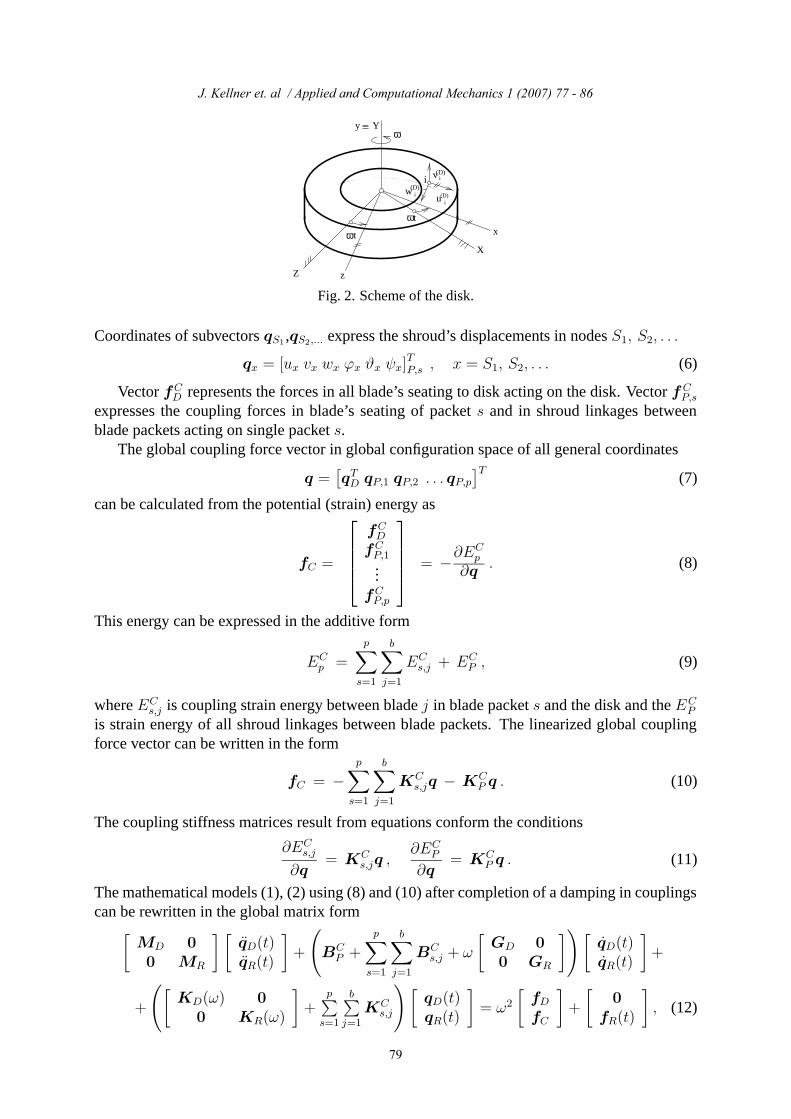
Fig. 2. Scheme of the disk.
Coordinates of subvectors qS1,qS2,... express the shroud’s displacements in nodes S1, S2, . . .
qx = [ux vx wx ϕx ϑx ψx]T
P,s , x = S1, S2, . . . (6)
Vector fCD represents the forces in all blade’s seating to disk acting on the disk. Vector fC
P,s
expresses the coupling forces in blade’s seating of packet s and in shroud linkages betweenblade packets acting on single packet s.
The global coupling force vector in global configuration space of all general coordinates
q =[
qTD qP,1 qP,2 . . . qP,p]T
(7)
can be calculated from the potential (strain) energy as
fC =
fCD
fCP,1...
fCP,p
= −∂ECp
∂q. (8)
This energy can be expressed in the additive form
ECp =
p∑
s=1
b∑
j=1
ECs,j + EC
P , (9)
where ECs,j is coupling strain energy between blade j in blade packet s and the disk and the EC
P
is strain energy of all shroud linkages between blade packets. The linearized global couplingforce vector can be written in the form
fC = −p∑
s=1
b∑
j=1
KCs,jq − KC
P q . (10)
The coupling stiffness matrices result from equations conform the conditions
∂ECs,j
∂q= KC
s,jq ,∂EC
P
∂q= KC
P q . (11)
The mathematical models (1), (2) using (8) and (10) after completion of a damping in couplingscan be rewritten in the global matrix form
[
MD 0
0 MR
] [
qD(t)qR(t)
]
+
(
BCP +
p∑
s=1
b∑
j=1
BCs,j + ω
[
GD 0
0 GR
]
)
[
qD(t)qR(t)
]
+
+
(
[
KD(ω) 0
0 KR(ω)
]
+p∑
s=1
b∑
j=1
KCs,j
)
[
qD(t)qR(t)
]
= ω2
[
fDfC
]
+
[
0
fR(t)
]
, (12)
J. Kellner et. al / Applied and Computational Mechanics 1 (2007) 77 - 86
79
J. Kellner et al. / Applied and Computational Mechanics XX (YYYY) XXX - YYY
whereqR =
[
qTP,1 qTP,2 . . . qTP,p]T ∈ RnR , nR = p nP (13)
is the general coordinate vector of a blading with shroud creating the blade rim (subscript R).The global stiffness matrix of the rotating disk has the form
KD(ω) = KsD − ω2KdD ∈ RnD,nD . (14)
The matrices of the blade rim are compiled from the blade packet matrices
XR = diag (XP , XP , . . .XP , ) ∈ RnR,nR , X = M ,G,Ks,Kd,Kω. (15)
The global stiffness blade rim matrix is
KR(ω) = KsR + ω2 (KωR −KdR) + KCPP ∈ RnR,nR , (16)
where KCPP is nonzero submatrix of the coupling stiffness matrix KC
P corresponding to subsys-tem R.
The centrifugal load vector of the blade rim is
fC =[
fTP fT
P . . . fTP
]T ∈ RnR (17)
and vector of the aerodynamic forces has the general form
fR(t) =[
fTP,1(t), fT
P,2(t), . . . , fTP,p(t)
]T ∈ RnR . (18)
It is advantageous to assemble condensed mathematical model of the rotating bladed diskwith reduced degrees of freedom (DOF) number, because mainly the three-dimensional elasticdisk could have large DOF number nD and blade rim DOF number is nR = p nP .
The modal transformations
qD(t) = mVDxD(t) , qR(t) = mVRxR(t) (19)
are introduced for this purpose. Matrices mVD ∈ RnD,mD and mVR ∈ RnR,mR are ”master”modal submatrices of subsystems D (disk) and R (blade rim) obtained from modal analysisof the mutually uncoupled (KC
s,j = 0 for all s, j) and non-rotating subsystems represented bymodels
MDqD(t) + KsDqD(t) = 0 , MRqR(t) +(
KsR + KCPP
)
qR(t) = 0 . (20)
A condensation (reduction in DOF number) of both systems is attached by selection of a set ofmD and mR subsystem master mode shapes (mD < nD, mR < nR). The new configurationspace of dimension m = mD + mR is defined by coordinate vector
x(t) =[
xTD(t) xTR(t)]T ∈ Rm . (21)
After the transformations (19) with considerations of the orthonormality conditionsmV T
D MDmVD = ED and mV T
R MRmVR = ER the model (12) can be rewritten in the
condensed form
x(t) +(
B + ωG)
x(t)+
+
(
Λ + ω2(
Kω − Kd
)
+ V T
(
p∑
s=1
b∑
j=1
KCs,j
)
V
)
x(t) = V T (ω2f0 + f(t)) , (22)
J. Kellner et. al / Applied and Computational Mechanics 1 (2007) 77 - 86
80
J. Kellner et al. / Applied and Computational Mechanics XX (YYYY) XXX - YYY
where
B = V T
(
BCP +
p∑
s=1
b∑
j=1
BCs,j
)
V ,
X = diag(
mV TD XD
mVD ,mV T
R XRmVR
)
∈ Rm,m
for X = G, Kd, Kω (with KωD = 0). Matrices
Λ = diag (mΛD ,mΛR) , V = diag (mVD ,
mVR) (23)
are composed from spectral and modal submatrices of the subsystems satisfying the conditions
mV TD KsD
mVD = mΛD ,
mV TR
(
KsR + KCPP
)mVR = m
ΛR . (24)
The vector f0 =[
fTD , fT
C
]Texpresses the influence of the centrifugal forces. The global vec-
tor of the aerodynamic forces in complex form is f(t) = feiωkt, where f =[
0T fT
R
]T. We
assume the harmonic blade excitation in axial (outspread to turbomachine rotor) and circumfer-ential (tangential) direction concentrated in blade nodes i (fig. 1) in the complex form
fB,j(t) = [. . . ;Fiy cosϕj,s + iFiy sinϕj,s;Fiz cosψj,s + iFiz sinψj,s; . . .] eiωkt , (25)
where ωk is dominant excitation frequency corresponding to number of stator nozzles multiplyangular velocity of the rotating disk. The angle ϕj,s is the phase angle of the aerodynamicforces acting on j-th blade in s-th blade packet in the axial direction and ψj,s is the phase anglein tangential direction on the same blade. These phase angles can be expressed in the form
ϕj,s = [j − 1 + (s− 1)3] 2πpSBpMB
, ψj,s = ϕj,s − ϕ , (26)
where ϕ is the relative phase shift between aerodynamic forces applied in axial and circumfer-ential direction [4] and pSB (pMB) is stator (rotor) blade number.
3. Forced vibration and stress analysis
For high-cycle fatigue we consider only aerodynamic forces acting on the moving blades,that’s why we don’t use below the constant centrifugal force f0 presented in (22). The steadydynamic response of the rotating bladed disk calculated at the condensed model (22) is of theform x(t) = xeiωkt with complex amplitude vector
x = Z−1V Tf , (27)
where
Z = −ω2kE + iωk
(
B + ωG)
+
(
Λ + ω2(
Kω − Kd
)
+ V T
(
p∑
s=1
b∑
j=1
KCs,j
)
V
)
(28)
is the dynamic stiffness matrix of the condensed model and f is vector of the complex ampli-tudes of the aerodynamic excitation. Damping matrices BC
P and BCs,j are considered as propor-
tional to stiffness matrices of the corresponding couplings. By using modal transformation weobtain the steady state solution in global configuration space
qeiωkt = V xeiωkt . (29)
J. Kellner et. al / Applied and Computational Mechanics 1 (2007) 77 - 86
81
J. Kellner et al. / Applied and Computational Mechanics XX (YYYY) XXX - YYY
This solution has the complex form and the real displacements of the excited rotating bladeddisk is the real part of the complex generalized coordinate vector
q(t) = Re{qeiωkt} . (30)
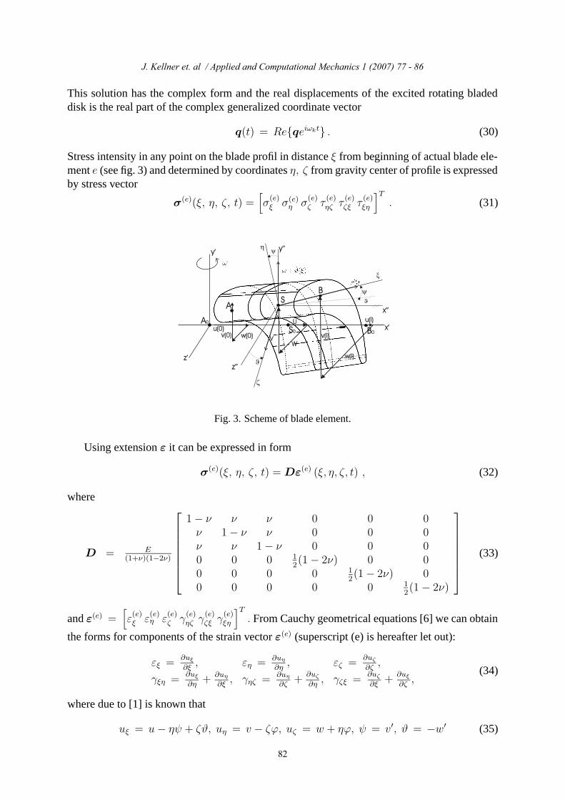
Stress intensity in any point on the blade profil in distance ξ from beginning of actual blade ele-ment e (see fig. 3) and determined by coordinates η, ζ from gravity center of profile is expressedby stress vector
σ(e)(ξ, η, ζ, t) =[
σ(e)ξ σ(e)
η σ(e)ζ τ
(e)ηζ τ
(e)ζξ τ
(e)ξη
]T
. (31)
Fig. 3. Scheme of blade element.
Using extension ε it can be expressed in form
σ(e)(ξ, η, ζ, t) = Dε(e) (ξ, η, ζ, t) , (32)
where
D = E(1+ν)(1−2ν)
1− ν ν ν 0 0 0ν 1− ν ν 0 0 0ν ν 1− ν 0 0 00 0 0 1
2(1− 2ν) 0 0
0 0 0 0 12(1− 2ν) 0
0 0 0 0 0 12(1− 2ν)
(33)
and ε(e) =[
ε(e)ξ ε
(e)η ε
(e)ζ γ
(e)ηζ γ
(e)ζξ γ
(e)ξη
]T
. From Cauchy geometrical equations [6] we can obtain
the forms for components of the strain vector ε(e) (superscript (e) is hereafter let out):
εξ =∂uξ
∂ξ, εη = ∂uη
∂η, εζ =
∂uζ
∂ζ,
γξη =∂uξ
∂η+ ∂uη
∂ξ, γηζ = ∂uη
∂ζ+
∂uζ
∂η, γζξ =
∂uζ
∂ξ+
∂uξ
∂ζ,
(34)
where due to [1] is known that
uξ = u− ηψ + ζϑ, uη = v − ζϕ, uζ = w + ηϕ, ψ = v′, ϑ = −w′ (35)
J. Kellner et. al / Applied and Computational Mechanics 1 (2007) 77 - 86
82
J. Kellner et al. / Applied and Computational Mechanics XX (YYYY) XXX - YYY
which leads to expressions
εξ = u′(ξ)− ηv′′(ξ)− ζw′′(ξ) = Ψ′S−1
3 q3 − ηΦ′′S−11 q1 − ζΦ′′S−1
2 q2,εη = v′(ξ)− ζϕ′(ξ) = Φ
′S−11 q1 − ζΨ′S−1
3 q4,εζ = w′(ξ) + ηϕ′(ξ) = Φ
′S−12 q2 + ηΨ′S−1
3 q4,γξη = −v′(ξ) + v′(ξ)− ζϕ′(ξ) = −ζΨ′S−1
3 q4,γηζ = −ϕ(ξ) + ϕ(ξ) = 0,γζξ = w′ + ηϕ′(ξ)− w′ = ηΨ′S−1
3 q4.
(36)
The displacements of internal points of the blade element were approximated by neglectingshear deformations in the form
u(ξ) = ΦS−13 q3, v(ξ) = ΦS−1
1 q1, w(ξ) = ΦS−12 q2,
ϕ(ξ) = ΨS−13 q4, ϑ(ξ) = −Φ
′S−12 q2, ψ(ξ) = Φ
′S−11 q1, (37)
where Φ = [1 ξ ξ2 ξ3], Ψ = [1 ξ] and vector of node displacements of the blade elements oflength A0 B0 = l was decomponated to subvectors
q1 = [v(0) ψ(0) v(l) ψ(l)]T , q2 = [w(0) ϑ(0) w(l) ϑ(l)]T ,
q3 = [u(0) u(l)]T , q4 = [ϕ(0) ϕ(l)]T . (38)
The form of matrices Si, i = 1, 2, 3 is presented in [1].Using relations (36) the strain vector can be rewritten into the matrix form
ε(e)(ξ, η, ζ, t) = A(e)(ξ, η, ζ)q(e)(t)
εξεηεζγηζγζξγξη
=
−ηΦ′′S−11 −ζΦ′′S−1
2 Ψ′S−1
3 0
Φ′S−1
1 0 0 −ζΨ′S−13
0 Φ′S−1
2 0 ηΨ′S−13
0 0 0 0
0 0 0 ηΨ′S−13
0 0 0 −ζΨ′S−13
q1
q2
q3
q4
.(39)
The equation (32) applied for concrete blade element in the complex form is
σ(e)s,j (ξ, η, ζ)e
iωkt = DA(e)(ξ, η, ζ)T q(e)s,j e
iωkt, (40)
where s is index of packet and j index of blade in packet s, T is transformation matrix betweenglobal and local coordinate system [1], q
(e)s,j is vector of complex displacement amplitudes of
the blade element in global system. That’s why the real stress vector is
σ(e)s,j (ξ, η, ζ, t) = Re
{
σ(e)s,j (ξ, η, ζ)e
iωkt}
= Re{(
σ(e)s,j + i ¯σ
(e)s,j
)
(cosωkt + i sinωkt)}
,
(41)σ
(e)s,j (ξ, η, ζ, t) = σ
(e)s,j cosωkt− ¯σ
(e)s,j sinωkt, (42)
where quantities marked by bar (x) are real parts and quantities with two bars ( ¯x) are imaginaryparts of complex vector components. Using Hubert-Misses-Hencky stress hypothesis [6] weobtain reduced stress
σ(e)red(ξ, η, ζ, t) =
1√2
√
(σξ − ση)2 + (ση − σζ)2 + (σξ − σζ)2 + 6(τ 2ζη + τ 2
ξη + τ 2ξζ), (43)
where σξ = σξ cosωkt− ¯σξ sinωkt, etc.
J. Kellner et. al / Applied and Computational Mechanics 1 (2007) 77 - 86
83
J. Kellner et al. / Applied and Computational Mechanics XX (YYYY) XXX - YYY
4. Application
On the basis of the presented method the original software in MATLAB code was created.The matrices of the disk were obtained by three-dimensional finite element method as is shownin [5]. The matrices of the blade rim were derived by one-dimensional finite element methodapplied to blades with shroud [9]. The aerodynamic forces applied in axial and tangential di-rection on each moving blade were assumed from [4]. The software and the proposed approachwas applied to the centrally clamped steel bladed disk characterized by following basic param-eters:
disk inner/outer radius 0.335/05754 mdisk thickness 0.155 mlength of blades 0.253 mwidth/thickness of shroud with rectangular profil 0.1005/0.014 mnumber of blades in packets b 3number of blade packets p 18DOF number of the discretized disk nD 3240DOF number of the discretized blade ring nR 3672Young’s modulus of the disk, blade and shroud materials E 2e11 PaPoisson’s ratio ν 0.3mass density % 7800 kg.m−3
amplitude of global axial force Fy acting on one blade 700 Namplitude of global tangential force Fz acting on one blade 1600 Nrelative phase shift between Fy and Fz 25
translation stiffnesses of the flexible blade seating in disk (fig.1)kxj
= kzj= 2, 8.109; kyj
= 4, 88.109 Nm−1
torsional/flexural stiffnesses of the flexible blade seating in disk (fig.1)kxjxj
= 1, 05.108; kyjyj= 1, 5.107 kzjzj
= 3.107 Nm.rad−1
stiffnesses linkages between blade packets (fig.1)ku = kv = kw = 109 Nm−1; kϕ = kψ = 107; kϑ = 106 Nm.rad−1
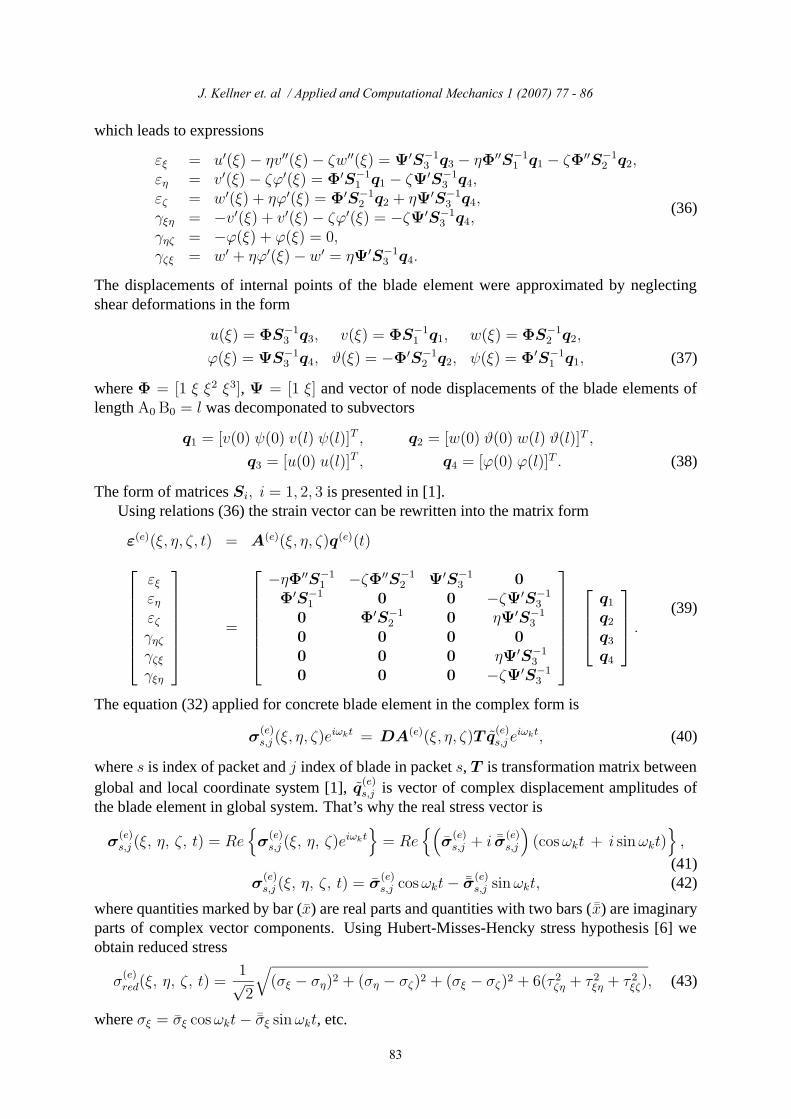
The time dependent normal stress σζ for excitation frequency corresponding to 3000 revo-lutions per minute of the disk and 32 number of stator nozzles in the blade cross-section of thethird element (the location of the blade profile for s = j, j = 1 in distance ξ = 0 and in gravitycenter) is drawn in fig. 4 because it has the greatest value of stress vector components. Alsothere is possibility to display components of vector σ
(e)s,j on the whole chosen blade profile for
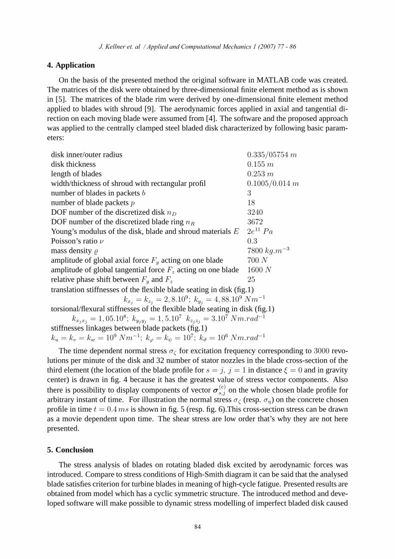
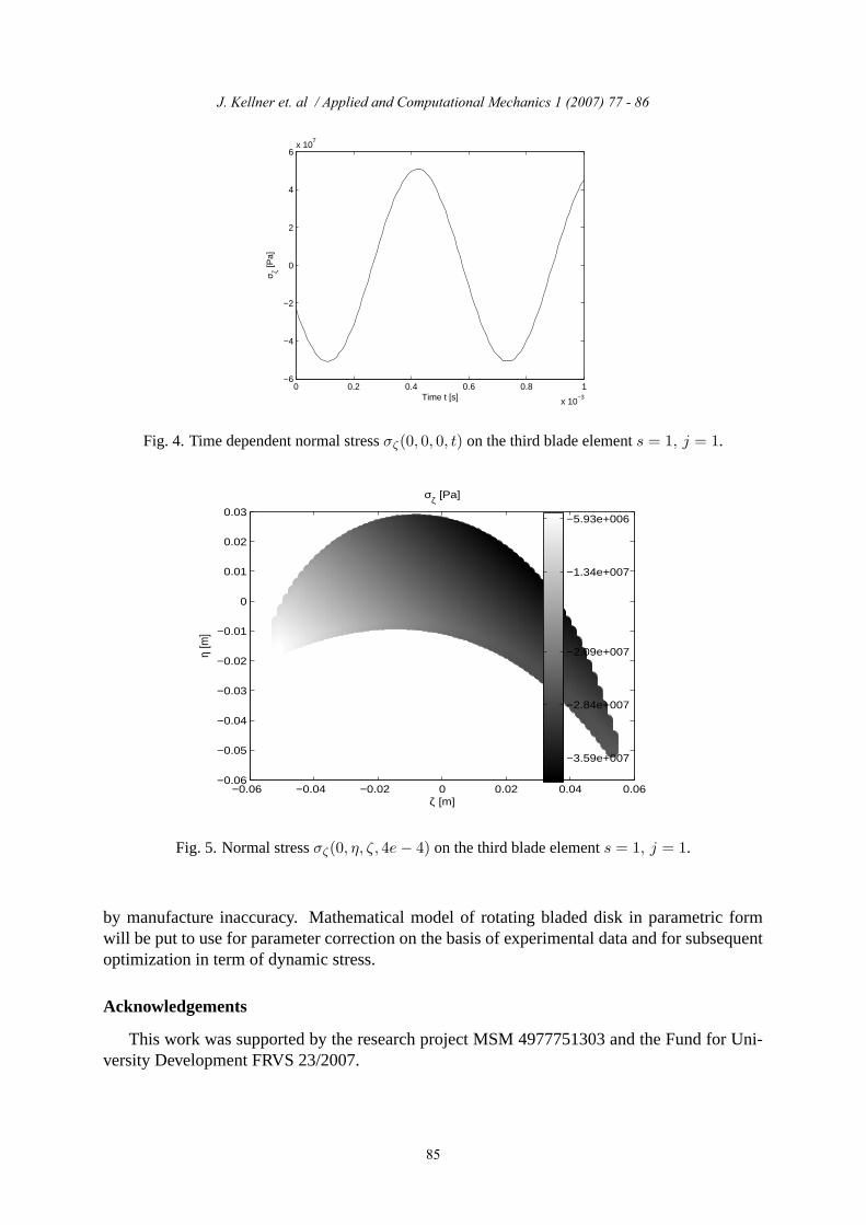
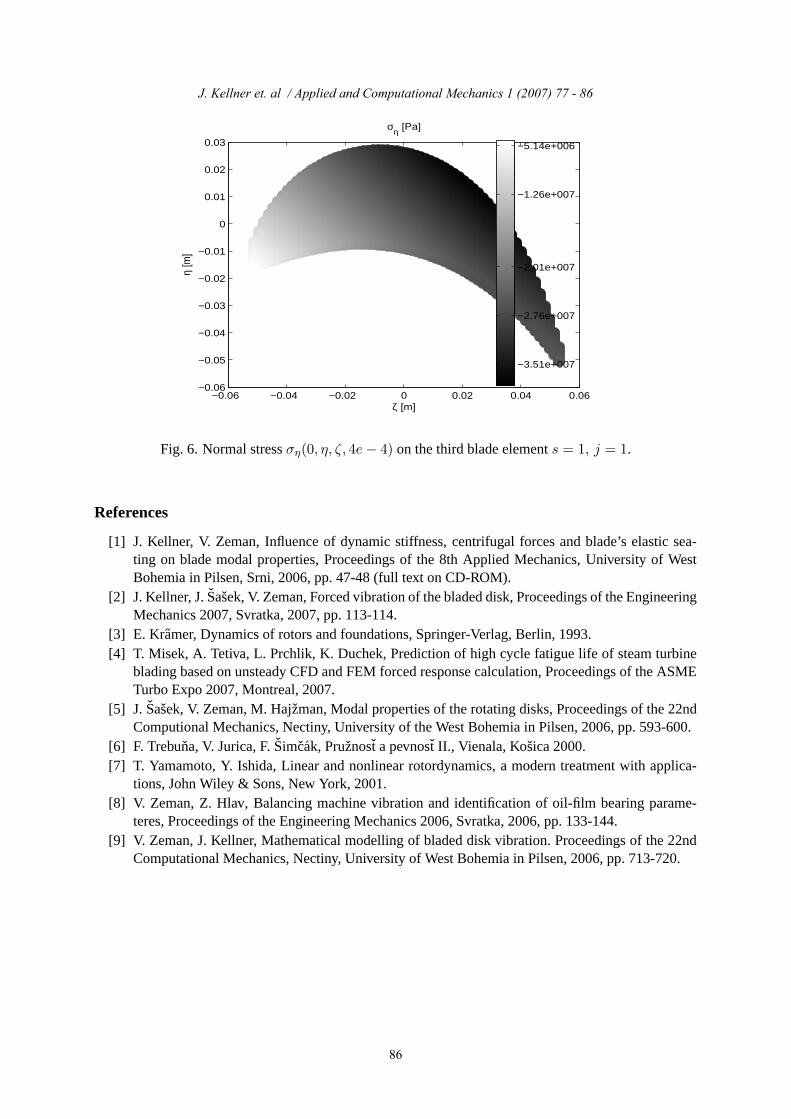
arbitrary instant of time. For illustration the normal stress σζ (resp. ση) on the concrete chosenprofile in time t = 0.4ms is shown in fig. 5 (resp. fig. 6).This cross-section stress can be drawnas a movie dependent upon time. The shear stress are low order that’s why they are not herepresented.
5. Conclusion
The stress analysis of blades on rotating bladed disk excited by aerodynamic forces wasintroduced. Compare to stress conditions of High-Smith diagram it can be said that the analysedblade satisfies criterion for turbine blades in meaning of high-cycle fatigue. Presented results areobtained from model which has a cyclic symmetric structure. The introduced method and deve-loped software will make possible to dynamic stress modelling of imperfect bladed disk caused
J. Kellner et. al / Applied and Computational Mechanics 1 (2007) 77 - 86
84
J. Kellner et al. / Applied and Computational Mechanics XX (YYYY) XXX - YYY
0 0.2 0.4 0.6 0.8 1
x 10−3
−6
−4
−2
0
2
4
6x 10
7
Time t [s]
σ ζ [Pa]
Fig. 4. Time dependent normal stress σζ(0, 0, 0, t) on the third blade element s = 1, j = 1.
−0.06 −0.04 −0.02 0 0.02 0.04 0.06−0.06
−0.05
−0.04
−0.03
−0.02
−0.01
0
0.01
0.02
0.03
ζ [m]
η [m
]
σζ [Pa]
−3.59e+007
−2.84e+007
−2.09e+007
−1.34e+007
−5.93e+006
Fig. 5. Normal stress σζ(0, η, ζ, 4e− 4) on the third blade element s = 1, j = 1.
by manufacture inaccuracy. Mathematical model of rotating bladed disk in parametric formwill be put to use for parameter correction on the basis of experimental data and for subsequentoptimization in term of dynamic stress.
Acknowledgements
This work was supported by the research project MSM 4977751303 and the Fund for Uni-versity Development FRVS 23/2007.
J. Kellner et. al / Applied and Computational Mechanics 1 (2007) 77 - 86
85
J. Kellner et al. / Applied and Computational Mechanics XX (YYYY) XXX - YYY
−0.06 −0.04 −0.02 0 0.02 0.04 0.06−0.06
−0.05
−0.04
−0.03
−0.02
−0.01
0
0.01
0.02
0.03
ζ [m]
η [m
]
ση [Pa]
−3.51e+007
−2.76e+007
−2.01e+007
−1.26e+007
−5.14e+006
Fig. 6. Normal stress ση(0, η, ζ, 4e− 4) on the third blade element s = 1, j = 1.
References
[1] J. Kellner, V. Zeman, Influence of dynamic stiffness, centrifugal forces and blade’s elastic sea-ting on blade modal properties, Proceedings of the 8th Applied Mechanics, University of WestBohemia in Pilsen, Srni, 2006, pp. 47-48 (full text on CD-ROM).
[2] J. Kellner, J. Sasek, V. Zeman, Forced vibration of the bladed disk, Proceedings of the EngineeringMechanics 2007, Svratka, 2007, pp. 113-114.
[3] E. Kramer, Dynamics of rotors and foundations, Springer-Verlag, Berlin, 1993.[4] T. Misek, A. Tetiva, L. Prchlik, K. Duchek, Prediction of high cycle fatigue life of steam turbine
blading based on unsteady CFD and FEM forced response calculation, Proceedings of the ASMETurbo Expo 2007, Montreal, 2007.
[5] J. Sasek, V. Zeman, M. Hajzman, Modal properties of the rotating disks, Proceedings of the 22ndComputional Mechanics, Nectiny, University of the West Bohemia in Pilsen, 2006, pp. 593-600.
[6] F. Trebuna, V. Jurica, F. Simcak, Pruznost a pevnost II., Vienala, Kosica 2000.[7] T. Yamamoto, Y. Ishida, Linear and nonlinear rotordynamics, a modern treatment with applica-
tions, John Wiley & Sons, New York, 2001.[8] V. Zeman, Z. Hlav, Balancing machine vibration and identification of oil-film bearing parame-
teres, Proceedings of the Engineering Mechanics 2006, Svratka, 2006, pp. 133-144.[9] V. Zeman, J. Kellner, Mathematical modelling of bladed disk vibration. Proceedings of the 22nd
Computational Mechanics, Nectiny, University of West Bohemia in Pilsen, 2006, pp. 713-720.
J. Kellner et. al / Applied and Computational Mechanics 1 (2007) 77 - 86
86