expanded decorrelating detector with reduced noise ...epubs.surrey.ac.uk/289944/1/j1.pdf ·...
TRANSCRIPT

1
Expanded Decorrelating Detector with Reduced Noise Enhancement for
Multipath Frequency-Selective Fading Channels
H. Zhou, P. Xiao, W. L. Woo, and B. S. Sharif
School of Electrical, Electronic and Computer Engineering, Merz Court,
Newcastle University, NE1 7RU
United Kingdom
Emails: {hongwei.zhou, pei.xiao, w.l.woo, bayan.sharif}@ncl.ac.uk
Abstract – A novel hybrid multiuser detection scheme that jointly uses linear and nonlinear
interference suppression techniques is developed for high-speed direct-sequence code-division
multiple-access (DS/CDMA) communications in multipath frequency-selective fading channels. The
detector detects signals in a symbol-by-symbol style. Conventional decorrelating detectors suffer from
the noise enhancement problem, and the problem becomes more serious for dispersive multipath
channels. The proposed detector uses interference cancellation (IC) technology to reduce the rank of
the expanded signal subspace and hence it enjoys the advantages of the expanded decorrelating
detector in terms of complete multiple access interference (MAI) and intersymbol interference (ISI)
suppression and avoids its disadvantage in terms of noise enhancement. Meanwhile, for this new
detection strategy, a novel Kalman filter-based adaptive power estimation algorithm is developed.
Computer simulation shows dramatic performance gain in the new detector compared with other
existing methods.
Index Terms: DS-CDMA, multiuser detection, expanded decorrelating detector, interference
cancellation, Kalman filter, amplitude estimation, multipath frequency-selective fading channel

2
I. Introduction
Code-division multiple-access (CDMA) is the core technique in all 3G mobile communication
standards. It is also used in satellite communications [1] and other wireless systems such as Wi-Fi [2]
and ZigBee [3]. Undoubtedly, CDMA will continue to play a pivotal role in future generation of
wireless communications. It is well known that CDMA communication systems are interference
limited, that is, the system capacity is limited by the multiple access interference (MAI) [4]. In the
recent decade, there have been significant efforts in developing multiuser detection technologies to
overcome the MAI problem. The maximum likelihood sequence estimator is the optimum detector in
terms of bit error rate (BER) performance [5], but its complexity grows exponentially with the number
of users, which is prohibitive for practical implementation. Linear multiuser detectors, such as the
decorrelating detector [4] [6] [7] and the minimum mean square error (MMSE) detector [8], are
suboptimum solutions, but they have low complexity, which only grows linearly with the number of
users. The adaptive detectors are preferable to their non-adaptive counterparts because they do not need
online computation of the crosscorrelation matrix and can adapt to dynamic environment by learning
from the received data. The adaptive MMSE detector introduced in [9] is derived using training
sequence and the stochastic gradient descent training algorithm. This training-based method does not
require users’ spreading codes, and is therefore suitable for downlink implementation. The need for
training sequence is further avoided in the blind multiuser detection scheme proposed in [10], where a
blind MMSE detector is developed by minimizing the mean output energy (MOE) subject to an
orthogonality constraint. Its adaptive implementation is realized by using the least-mean-square (LMS)
method. Another approach to blind detection is based on subspace estimation. In [11], the decorrelating
detector and the MMSE detector are expressed in closed forms of the signal subspace components, and
the signal subspace is tracked by using the project approximation subspace tracking deflation (PASTd)
algorithm. This subspace approach is extended to the antenna array system in [12], resulting in a blind
subspace-based spatio-temporal decorrelator and spatio-temporal MMSE detector. In [13] and [14], the
blind detectors are expressed as variables in the signal subspace and the coefficients are adaptively
derived by LMS and Kalman filtering methods, respectively. Parallel to the development of the linear
detectors, there are also numerous efforts in developing interference cancellation (IC) technologies [4]
[15] [16]. IC is a category of nonlinear methods that subtract the estimated interfering signals when
demodulating the signal of the interested user. There are basically two classes of IC techniques-

3
successive interference cancellation (SIC) [15] which subtracts interference in a sequential order, one
user at a time; and parallel interference cancellation (PIC) [16] which subtracts the interference from all
interfering users simultaneously. IC detectors are bootstrapping technologies- correct decisions will
lead to correct recreation and subtraction of the interfering signals at the receiver, while wrong
decisions will double the contribution of the interferer, so conventional IC methods are only suitable
for high SNR environments.
In practical high-speed wireless communications, the intersymbol interference (ISI) caused by
multipath propagation imposes significant concern. One way to overcome the effect of ISI is to
employ multicarrier technique to transform a frequency selective fading channel to flat fading channels
[17] [18] [19]. However, since the multipath signals become non-resolvable, the multicarrier
approaches forgo the opportunity to make use of the effective multipath diversity gain. RAKE receiver
is commonly used to solve the multipath problem [20], but it is optimum only in single-user systems.
For multiuser systems, the RAKE structure can still be used but the matched filters in the front end are
replaced by linear multiuser detectors [21] [22] [23]. In [24], the MOE detector in [10] is extended into
multipath channel by using a Min/Max approach to simultaneously optimize the output energy and a
constraint vector. The optimal constraint vector is a biased estimate of the channel vector. The
estimation error is proportional to the channel noise and it causes inferior performance compared with
the MMSE detector. In [25], the affect of noise is mitigated by using a Power of R (POR) method to
virtually increase the SNR. Emphasis of this paper is the decorrelating detectors, which have been
proposed in [6] [7] and [11] for multiuser detection in AWGN channel. For multipath frequency-
selective fading channel, the ISI is modelled as virtual MAI in [26] and hence an expanded
decorrelating detector is derived to simultaneously suppress MAI and ISI. The expanded decorrelating
detectors are not limited by the channel length. Meanwhile, they maintain the desirable properties of
distributed implementation and having no detection delays. However, all decorrelating detectors have
the disadvantage of noise enhancement, and the expanded decorrelating detector operating in a higher-
rank subspace amplifies the noise even more significantly. This paper aims at solving this problem by
using a hybrid detection strategy that combines linear and nonlinear methods to effectively suppress
both MAI and ISI without noise enhancement. The rationale is that the received signals in
neighbouring time epochs are highly correlated after convolving with multipath channel. Therefore, the

4
detected information bits in one time epoch can be used to improve the signal detection in the next time
epoch, e.g., the interfering signals from the previous epochs are deducted from the received signal so
that the quality of detection can be improved. The direct result is that the decorrelating detector
operates in a rank-reduced signal subspace and the noise enhancement factor is reduced and keeps
static over a wide range of multipath spreads and number of user. The performance gain is especially
significant for systems with long delay spread and heavy loads. Meanwhile, the rank-reduced
decorrelating detector has reduced complexity compared with the conventional expanded decorrelating
detectors. And the decorrelating detector mitigates the error propagation problem caused by incorrect
decision feedback. An iterative detection strategy can be further derived from this hybrid structure. In
each iteration, by feeding back and forward the information from the decorrelating detector, all ISI can
be deducted from the input signal so that the decorrelating detector operates in a signal subspace with
further reduced rank. Performance gains are obtained compared to the non-recursive hybrid detector,
but the improvement is not significant, since the latter has already approached the performance of the
decorrelating detector in Gaussian channel. This novel hybrid detection structure which brings
improved performance is the first contribution of this paper.
The second contribution is the development of a Kalman filter-based amplitude/power estimation
algorithm. The estimated amplitudes are then used by the IC scheme. Kalman filter is well known in
the optimal statistical estimation and control theory [27]. When the linear and Gaussian assumptions
hold, no other algorithms can outperform Kalman filter [28]. Kalman filter has previously been used
for blind and nonblind multiuser detection [14] [29]. In this paper, we show that Kalman filter and
decorrelating detector can be perfectly integrated together to estimate the signal amplitudes for the
purpose of interference cancellation. One of the desirable properties of the decorrelating detector is that
it does not require any a priori information of the signal amplitudes (thus it is immune to the near-far
effect). However, in this work, we take advantage of the fact that the output of the decorrelating
detector actually contains rich amplitude information, and both soft and hard information can be
utilized by the Kalman filter to estimate the amplitudes. The proposed adaptive amplitude estimation
algorithm converges fast and tracks accurately.

5
The third contribution of this paper is to develop a remedy algorithm to deal with the subspace collapse
problem, which could happen to the expanded decorrelating detectors when the subspace rank is
deficient under certain channel conditions. This problem can severely deteriorate the performance of
the detector. The proposed remedy algorithm detects the rank deficiency and prevents malfunction in
the expanded decorrelating detector.
This paper is focused on the synchronous multipath channel. However, asynchronous multipath
channels can be modelled similarly as the one of synchronous channels. The only difference between
them is the time shift of the interfering signals (both ISI and MAI) according to the relative delay of
each user. With the known or estimated delay information, the proposed hybrid detection strategy can
be easily extended to asynchronous channels.
II. Signal Model for Multipath Synchronous Channel
We consider a synchronous K-user direct-sequence (DS) CDMA system employing binary phase-shift
keying (BPSK) modulation to transmit signal over multipath frequency-selective fading channels, as
illustrated in Figure 1. The signal transmitted by the kth user can be written as
( ) ( ) ( )k k k ki
x t A b i c t iT∞
=−∞
= −∑ (1)
where kA , ( )kb i and ( )kc t are the amplitude, ith transmitted information bit, and normalized signature
waveform of the kth user, respectively; T is the symbol interval. ( ) { 1, 1}kb i ∈ + − follows identical and
independent distribution (i.i.d.), and ( )kc t is defined in [0,T]. In DS-CDMA systems, ( )kc t is of the
form
1
0
( ) ( ) ( ), [0, ], 1,...,N
k k cn
c t c n t nT t T k Kψ−
=
= − ∈ =∑ (2)
where N is the spreading gain; 10{ ( )} N
k nc n −= is the real-valued and normalized signature code assigned to
the kth user, 1 2
0( ) 1
N
knc n
−
==∑ ; cT is the chip interval, cNT T= ; ( )tψ is a normalized chip waveform
defined in [0, ]cT , 2
0( ) 1
cTt dtψ =∫ .
In the case when a spreading sequence bandwidth W is much larger than the coherence channel

6
bandwidth, the tapped delay line model is widely used for multipath frequency-selective channels
(Chap.4, [14]). In this work, we adopt a tapped delay line model with tap spacing 1/W and tap
coefficients 10{ ( )} L
k lh l −= , where L is the number of resolvable paths for each user. We consider the case
where 1 cW T= , m cL T T= , and mT is the multipath delay spread. In literature, it is usually
assumed thatL N< , i.e., the multipath spread is less than one symbol duration. In this paper, we
consider a more general and realistic scenario in high-speed CDMA communications where the delay
spread can be arbitrarily long. The impulse response of the multipath channel is modeled as
1
0
( ) ( ) ( )L
k kl
lh t h l t
Wδ
−
=
= −∑ (3)
where ( )tδ is the Dirac's delta function. Transmitting the signals over the multipath channel expressed
by (3), the received signal due to the kth user is given by
( ) ( ) * ( )k k ky t x t h t= 1
0
( ) ( ) ( )L
k k k ki l
lA b i h l c t iT
W
∞ −
=−∞ =
= − −∑ ∑
(4)
where ‘*’ denotes the convolution operation. Finally, the total received signal is the superposition of K
users’ information-bearing data signals plus the AWGN, and can be expressed as
1
( ) ( ) ( )K
kk
r t y t v t=
= +∑ (5)
where ( )v t is a zero-mean white Gaussian noise. For simplicity, synchronous channel is the focus of
this paper, however, the proposed scheme can be readily extended to asynchronous channels.
The received signal is filtered by a chip-matched filter and then sampled at chip rate, resulting in a
discrete-time format of the signal model, in which the signal component due to the pth chip of the mth
symbol from the kth user is given by
( 1)( , ) ( ) ( )
c
c
mT p T
k k cmT pTy m p y t t mT pT dtψ
+ +
+= − −∫
1 1 ( 1)
0 0
( ) ( ) ( ) ( ) ( )c
c
L N mT p T
k k k k c c cmT pTi l n
A b i h l c n t iT lT nT t mT pT dtψ ψ∞ − − + +
+=−∞ = =
= − − − − −∑ ∑ ∑ ∫
1 1
00 0
( ) ( ) ( ) [ ( ) ( ) ] ( )c
L N T
k k k k ci l n
A b i h l c n t m i T p l n T t dtψ ψ∞ − −
=−∞ = =
= + − + − −∑ ∑ ∑ ∫
1
0
( ) ( ) ( )L
k k k ki l
A b i h l c p mN l iN∞ −
=−∞ =
= + − −∑ ∑
(6)

7
Define j p mN= + , ( ) ( , )k ky j y m p= , equation (6) can be rewritten as
1
0
( ) ( ) ( ) ( )L
k k k k ki l
y j A b i h l c j l iN∞ −
=−∞ =
= − −∑ ∑ ( ) ( )k k ki
A b i s j iN∞
=−∞
= −∑ (7)
where
1
0
( ) ( ) ( )L
k k kl
s n h l c n l−∆
== −∑ (8)
Comparing (7) with (1), one can see that the received signature code is the distorted version of the
original signature code after convolving with the multipath channel. Finally, the total received signal is
expressed in discrete-time format as
1
( ) ( ) ( )K
kk
r j y j v j=
= +∑ (9)
where ( 1)
( ) ( ) ( )c
c
j T
cjTv j v t t jT dtψ
+= −∫ .
At the output of the transmitter, the energy of each symbol is limited to duration cNT . However, a
close examination at (8) reveals that in the received signal, the energy of each symbol has been spread
over an extended interval ( 1) cN L T+ − due to the channel convolution, and hence the original
spreading sequence { } 1
0( )
N
k nc n
−
= of the length N becomes the actual received signature sequence
{ } 2
0( )
N L
k ns n
+ −
= of length N+L-1. Naturally, we employ an (N+L-1)-observation window as illustrated in
Figure 2. Note that this diagram just shows a special case when N<L<2N, but in the theoretical
derivation, we do not impose any constraint on the value of L. To detect each information bit, N+L-1
samples are stacked to form the received signal vector, and L-1 samples of them can be reused to detect
the next bit, leading to some saving in sampling time and memory. Falling within the observation
window are not only the information bits at the current time instant, but also those from the preceded
instants and the succeeded instants. The received signal vector therefore contains intersymbol
interference from the past as well as from the future symbols. To state this problem more clearly, we
define ( 1)def
P L N= − . Then, in the processing window of length N+L-1, 2P+1 symbols of the
desired user are involved, including the current symbol, P symbols before and P symbols after the
current symbol. Taking account of all the K users, there are (2P+1)K symbols involved in detecting

8
each symbol from the desired user. To summarize, the ( 1) 1N L+ − × -dimensional received signal
vector for this system can be expressed as
1
( ) ( ) ( )K
kk
i i i=
= +∑r y v
, ,1 1 1
( ) ( ) ( ) ( )K P P
k k k k k k j k k kk jk j j
A b i A b i j A b i j i= = =
= + − + + +
∑ ∑ ∑s s s v
(10)
where
, ,1 1
( ) ( ) ( ) ( )P P
k k k k k k k j k k kk jj j
i A b i A b i j A b i j= =
= + − + +∑ ∑y s s s (11)
[ ](0) ... ( 2)T
k k ks s N L= + −s (12)
[ ], ( ) ( 1) ... ( 2) 0 ... 0 , 1...T
k j k k ks jN s jN s N L j P= + + − =s (13)
[ ], 0 ... 0 (0) (1) ... ( 2 ) , 1...T
k j k k ks s s N L jN j P= + − − =s (14)
[ ]( ) ( ) ... ( 2)T
i v iN v iN N L= + + −v
Each element of the ( 1) 1N L+ − × -dimensional noise vector ( )iv has variance 2σ I . When
1L = (hence 0P = ) and (1) 1, 1...kh k K= = , ,k js in (13) and ,k js in (14) will be zero according to the
definition of ( )ks n in (8), and (10) is simplified to the model for the single-path flat fading channel
1
( ) ( ) ( )K
k k kk
i A b i i=
= +∑r c v
Defining
,1 , ( 1)...k k k P N L P+ − ×
= s s s (15)
,1 , ( 1)...k k k P N L P+ − ×
= s s s (16)
1 1 1 ( 1) (2 1)... K K K N L P K+ − × +
= S s s s s s s (17)
1 1
2 1 2 1
{ ... ... ... }K K
P P
diag A A A A+ +
=A14243 1442443
(18)
[ ]1 (2 1)
( ) ( ) ( 1) ... ( ) ( 1) ... ( ) , 1...k k k k k k Pi b i b i b i P b i b i P k K
× += − − + + =b (19)
[ ]1( ) ( ) ... ( )T
Ki i i=b b b (20)

9
then (10) can be written in a more compact vector/matrix format as
( ) ( ) ( )i i i= +r SAb v (21)
Assume that 1{ } K
k k=s , 1{ } Kk k=s and 1{ } K
k k=s are independent vectors, then the column vectors of S spans the
signal subspace ( 1) (2 1)N L P K+ − × +ℜ . Compared with the AWGN channel in which the signal subspace is
N K×ℜ , the rank of the signal subspace for the multipath channel is 2PK higher. For the signal model in
(21), the linear multiuser detection for the kth user is to do correlation and then take hard decision, i.e.,
ˆ ( ) sgn( ( ))Tk kb i i= d r (22)
where 1N Lk
+ −∈ℜd . Similar to [26], three linear multiuser detectors can be obtained as follows:
1) Linear Expanded Decorrelating Detector
Assume that all users’ spreading codes are known at the receiver, the expanded decorrelating detector
for the first user is given by
11 ,1
−
• = d S M
(23)
where 1
,1
−
• M denotes the kth column of the matrix 1−M , and
T=M S S (24)
1d is a (N+L-1)-vector. It completely removes MAI and ISI.
2) Expanded Subspace-Based Decorrelating Detector
In [11], blind multiuser detectors are expressed in the closed format of subspace components without
need of the interfering users’ spreading codes. The expanded subspace-based decorrelating detector in
this subsection and the expanded subspace-based MMSE detector in the next subsection are the
extension of them from the AWGN channel to multipath channels. In this paper, we assume that
channels are known; hence the expanded subspace-based detectors are not blind. The eigenvectors and
eigenvalues of the signal subspace can be obtained, e.g., by conducting eigendecomposition on the
autocorrelation matrix { }TE rr . The decorrelating detector is given by
1 11 1 1 1
T T Ts s s s s s
− − = d UΛ
U s s UΛ
U s
(25)

10
where sU is ( 1) (2 1)N L P K+ − × + matrix which columns are the eigenvectors for the signal subspace,
and s
Λ is a (2 1) (2 1)P K P K+ × + diagonal matrix which diagonal elements are the corresponding
eigenvalues.
3) Expanded Subspace-Based MMSE Detector
The MMSE detector expressed in closed form of the expanded signal subspace components is given by
2 1 2 11 1 1 1( ) ( )T T T
s s s s s s s sσ σ− − = + + d U Λ I U s s U Λ I U s (26)
where sI is a (2 1) (2 1)P K P K+ × + identity matrix.
Discussion:
1. Given that the estimated eigencomponents in (25) are accurate, the decorrelating detectors in (23)
and (25) give identical performance because they are the same detector of different expressions. Both
suffer the noise enhancement problem. The noise is enhanced more when the subspace rank increases,
as will be shown by simulation. The increase in subspace rank can be result of the increasing number of
users or longer channel spread.
III. The Hybrid Multiuser Detector
In this section, we develop a hybrid multiuser detector which is designed to tackle the noise
enhancement problem inherent to the decorrelating detectors introduced in the previous section. The
structure of the proposed receiver is illustrated in Figure 3. The received signal ( )ir is pre-processed
by subtracting the interfering signal ˆ( )i−I which is contributed by the symbols in the previous epochs,
and then the resulting signal ( )ir% is fed into the rank-reduced expanded decorrelating detector. Hard
decision of the decorrelating detector forms the estimate of the symbol bits ˆ ( )ib . Both the soft decision
and the hard decision ˆ ( )ib are sent into the Kalman filter bank to track the signal amplitudes of all
users. Finally the estimated amplitudes { }1
ˆ ( )K
kk
A i=
and the estimated bits ˆ ( )ib are sent to the ISI
synthesiser to recreate the interference signals, which will be used by the interference canceller in pre-
processing the next received signal.

11
A. Interference Synthesis and Cancellation
The item ,1 1
( )K P
k k k jk j
A b i j= =
−∑∑ s in (10) is due to the interfering signals from the previous epochs. They
can be recreated by the ISI synthesiser at time i because the bits before time i have already been
detected. With the estimated amplitudes { }1
ˆ ( 1)K
kk
A i=
− and the detected bits { }1... , 1...
ˆ ( )kj P k K
b i j= =
− , the
interference due to the previous symbols are recreated as
,1 1
ˆˆˆ( ) ( 1) ( )K P
k k k jk j
i A i b i j= =
− = − −∑∑I s
(27)
Interference cancellation results in the deflated received signal as given by
ˆ( ) ( ) ( )i i i= − −r r I%
, ,1 1 1
ˆˆ( ) ( ) ( 1) ( ) ( ) ( )K P P
k k k k k k k k j k k kk jk j j
A b i A b i j A i b i j A b i j i= = =
= + − − − − + + +
∑ ∑ ∑s s s v
,1 1
( ) ( ) ( )K P
k k k k k kk jk j
A b i A b i j i= =
≈ + + +
∑ ∑s s v (28)
The approximation in (28) is valid when the adaptive estimations of ̂ ( 1)kA i − and ˆ ( )k i j−b converge.
B. Rank-Reduced Expanded Decorrelating Detector
The rank of the original expanded signal subspace for (10) is (2P+1)K. The interference cancellation
reduces the subspace rank by PK. Hence the remaining rank for the deflated signal in (28) is (P+1)K.
Define
1 1 ( 1) ( 1)... K K N L P K+ − × +
= S s s s s% (29)
The rank-reduced expanded decorrelating detector for the kth user is
1
,k k
−
• = d S M%% %
(30)
where
T=M S S% %% (31)
C. Amplitude Estimation Using Kalman Filter
In stationary or slowly-time varying system, the signal amplitudes do not change within one symbol
duration. Thus, for the kth user, the state transition equation is given by

12
( ) ( 1)k kA i A i= − (32)
The output of the kth user’s decorrelating detector is
( ) ( ) ( ) ( ) ( )T Tk k k k kz i i b i A i i= = +d r d v% %% (33)
Equation (33) is the measurement equation because it relates the state variable ( )kA i to the
measurement ( )kz i . The measurement matrix is ( )kb i which is time-varying (here it is a scalar and
takes value in { }1, 1+ − ). Obviously, the mean and covariance of the process noise in (32) are zeros.
The measurement noise in (33) is ( )Tk id v% with mean and covariance
{ } { }( ) ( ) 0T Tk kE i E i= =d v d v% %
(34)
{ } { } 2cov ( ) ( ) ( )T T T Tk k k k ki E i iξ σ= = =d v d v v d d d% % % % %
(35)
Replacing ( )kb i in (33) with its estimation
( )ˆ ( ) sgn ( )k kb i z i=
(36)
the measurement equation is reformed as
ˆ( ) ( ) ( ) ( )Tk k k kz i b i A i i= + d v% (37)
Based on (32) and (37), the resulting Kalman filtering estimation routine is summarized in Table 1. The
computational complexity including interference cancellation and Kalman filtering is 2( )O P KN .
Table 1: Amplitude estimation algoritmm using Kalman filter
/* Initialization: */
(0) 0kA = , (0) 1P =
(38)
/* Estimation */
FOR i=1, 2, …
(39)
( ) ( )Tk kz i i= d r%
(40)
( )ˆ ( ) sgn ( )k kb i z i=
(41)
1ˆ( ) ( 1) ( )( ( 1) )kK i P i b i P i ξ −= − − +
(42)

13
ˆ( ) (1 ( ) ( )) ( 1)kP i K i b i P i= − −
(43)
ˆ( ) ( 1) ( )( ( ) ( ) ( 1))k k k k kA i A i K i z i b i A i= − + − −
(44)
END (45)
D. Iterative Multiuser Detection
In Figure 3, only the intersymbol interference from the previous epochs is cancelled. In the first
detection iteration, the ISI due to the symbols of the future epochs are not known and hence cannot be
cancelled. After the whole frame of signals have been detected, the estimated information bits can be
fed back, and then the interference due to the future epochs can be cancelled in the same way as the
previous epochs. The rank of the resulting signal subspace will be further reduced to K. The
interference cancellation and decorrelating detection procedures can be operated on the same signal
frame repeatedly, and the performance of the detection can be improved in an iterative manner. Figure
4 illustrates this idea. The deflated received signal becomes
ˆ ˆ( ) ( ) ( ) ( )i i i i= − − − +r r I I%
(46)
where ̂ ( )i+I is the recreated interfering signals due to the future epochs, and is defined as
,1 1
ˆˆˆ( ) ( 1) ( )K P
k k k jk j
i A i b i j= =
+ = − +∑∑I s
(47)
For the iterative detection, (29) is changed to
[ ]1 2 ( 1)... K N L K+ − ×
=S s s s%% (48)
The rank-reduced decorrelating detector for the kth user is
1
,k
k
−
•
= d S M%% %%% %
(49)
where
T=M S S% %% % %% (50)

14
IV. Subspace Collapse and Remedy Algorithm
In computing the expanded decorrelating detectors in (23) and (30), we have assumed that all column
vectors of S (see (17)) and S% (see (29)) are linearly independent. However, this is not always
guaranteed in practice. As an example, for zero-padded ,k ps and ,k ps , 1,...,k K= and 1,...,p P= ,
if 1 ( 1) 1L P N− = − + , then [ ]1, 1( 1) 0 ... 0T
P s PN= +s , …, [ ], ( 1) 0 ... 0T
K P Ks PN= +s are
correlated; and [ ]1, 10 0 ... (0)T
P s=s , …, [ ], 0 0 ... (0)T
K P Ks=s are also correlated. The
column vectors of S do not span subspace (2 1) ( 1)P K N L+ × + −ℜ , and the column vectors of S% do not span
subspace ( 1) ( 1)P K N L+ × + −ℜ . We say that the expanded signal subspace has collapsed. The expanded
decorrelating detectors in (23) and (30) are no longer valid as an immediate consequence of subspace
collapse. In order to tackle this problem, we propose a remedy algorithm as outlined in Table 2 to
detect the subspace collapse and then compute the expanded detectors in the new subspace. The
method is to remove the column vectors that are not independent. Because column vectors in
{ }Kkk 1=s have the full energy of the current symbols and they are usually linearly independent, the
removing operation will only be carried out to the vectors , 1{ } Pk τ τ =s and , 1{ } P
k τ τ =s , 1...k K= . Since the
methods are the similar for the expanded detector in (23) and the rank-reduced expanded detector in
(30), we only outline the algorithm for the rank-reduced expanded detector as in Table 2.
Table 2: Remedy Algorithm for the Rank-Reduced Expanded Decorrelating Detector
Calculate ks , k = 1,…K
Form matrix: [ ]1 ... K=S s s%
For k = 1:K /*K users*/ For 1: Pτ = /*P symbol duration*/
Form τ,ks ;
If τ,ks and the column vectors of S% are linearly independent
,k τ = S S s% %
End End End /*form the decorrelating detector*/
1T T
− = D S S S% % %%
1 ,1
T
• = d D% %

15
V. Performance Analysis
Signal-to-interference-plus-noise ratio (SINR) in the output of the linear detector for the kth user at
time i is defined as
{ }( ){ }
2
2
( )( )
( ) ( )
Tk k k k
Tk k k k
E A b iSINR i
E i A b i
=
−
d s
d r s (51)
For the full-rank expanded decorrelating detector,
1Tk k =d s
0Tk l =d s , l k≠
0Tk l =d s , l∀
0Tk l =d s , l∀
so the SINR in its output is
2 2
2 2( ) k k
full Tk k k
A ASINR i
σ α σ= =
d d (52)
where Tk k kα = d d is the noise enhancement factor. Compared with the SNR in the received signal
which is 2 2kA σ , SINR in (52) is reduced by kα times, or equally, the noise is amplified by kα times.
To gain more insight of the structure of the noise enhancement factor, it can be expressed as
1 1
, ,
Tk k k
α − −
• • = M S S M
1 1
, ,k k
− −
• • = M M M
( ) 1
,
T
k k
− = S S
(53)
It equals the kth main diagonal element of the matrix ( ) 1T −S S . Expressing (52) in log format shows the
connection between the output SINR and the SNR in the received signal as follows
2
10 10 102( ) log log log ( )k
full k k
ASINR i SNR dBα α
σ= − = −
(54)
For the rank-reduced expanded decorrelating detector, the interference that is not completely cancelled
can be modelled as Gaussian noise with variance 2Iσ . Then the SINR is given by

16
( ) ( )2 2
2 2 2 2( ) k k
reduce Tk k I k I
A ASINR i
σ σ α σ σ= =
+ +d d% % % (55)
where Tk k kα = d d% %% , and similarly it has structure
( ) 1
,
Tk
k k
α− =
S S% %%
(56)
After the Kalman filter converges, ˆ( )i−I is almost equal to ,1 1
( 1) ( )K P
k k k jk j
A i b i j= =
− −∑∑ s , and 2 0Iσ ≈ ,
then the log format of (55) is given by
10( ) log ( )reduce kSINR i SNR dBα= − % (57)
After convergence, the SINR improvement achieved by the proposed hybrid detector over the full-rank
expanded decorrelating detector is given by
10 10( ) ( ) ( ) log log ( )reduce full k kSINR i SINR i SINR i dBα α∆ = − = − % (58)
Equation (58) shows that the performance improvement is decided by the decorrelating detector and is
independent of the input SNR.
VI. Numerical Results
The proposed algorithms are evaluated by computer simulation in this section. Assume that there are
10 users in the synchronous DS-CDMA system unless otherwise stated (K=10). User 1 is the interested
user. Users’ transmission power is unbalanced: compared with user 1, users 2-6 are 10dB stronger,
users 7-9 are 20dB stronger and user 10 is 30dB stronger, respectively. The spreading codes are
randomly-generated, independent and normalized sequences and the spreading gain is N=31. The
multipath channel coefficients are randomly-generated and normalized and have exponential decay
profile. For the blind multiuser detectors, 5000 symbols are used to estimate signal subspace. All
results are averaged over 500 Monte-Carlo runs in order to yield reliable statistics. SNR values are
measured by comparing the power of user 1 and the background noise. In all simulations, the
measurement noise variance ξ in (42) is set to 0.1.
Example 1: Amplitude tracking. Since amplitude estimation plays an important role in the proposed
detection strategy, we study the effectiveness of the Kalman filter-based amplitude tracking algorithm
in different scenarios. Figure 5 shows the amplitude tracking performance of all users when the

17
multipath channel spread is 25 and the input SNR is 20dB. It shows that the adaptive process converges
fast and the power estimation of all users is almost precise after about 50 iterations. The following
examples are focused on the first user. In Figure 6, the multipath spread is 25 and the input SNR varies
from 5dB to 20dB. It can be seen that SNR at moderate or higher level is good for accurate power
estimation, at lower SNR level, there is some loss in estimation accuracy (about 5%). Figure 7 shows
amplitude tracking when SNR is 20dB and the multipath channel spreads vary from 25, which is less
than one symbol interval, to 86, which is over two symbol intervals. It can be seen that the amplitude
estimation algorithm is not significantly affected by the channel spreads.
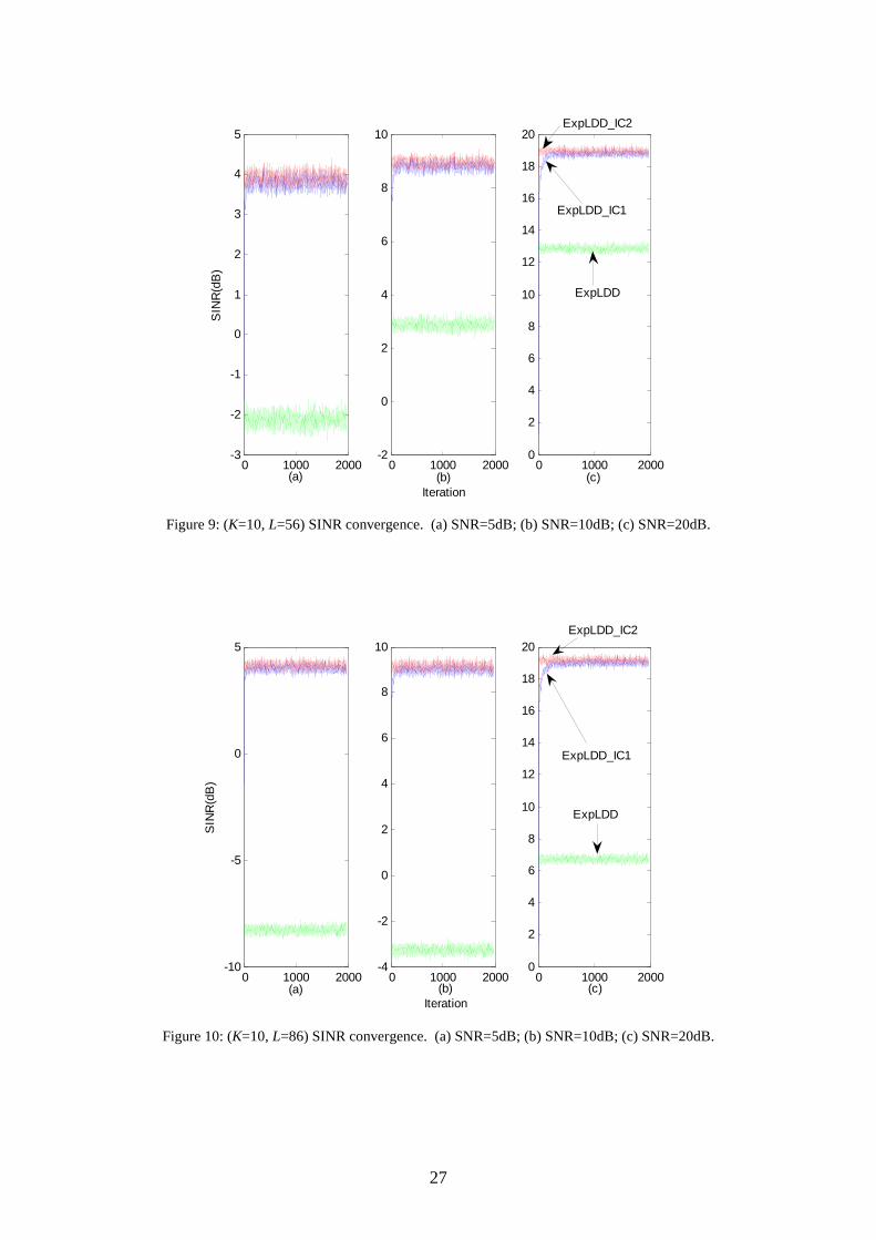
Example 2: SINR performance. Figure 8 to Figure 10 compare the SINR performance of three
multiuser detectors at different multipath channels and different input SNR levels. The investigated
detectors are the expanded decorrelating detector (ExpLDD), the rank-reduced expanded decorrelating
detector assisted by fed-forward interference cancellation (ExpLDD_IC1), and the rank-reduced
expanded decorrelating detector assisted by fed-forward and fed-back interference cancellation
(ExpLDD_IC2). The figures show that both rank-reduced expanded decorrelating detectors obtain
dramatic performance improvement compared with the full-rank expanded decorrelating detector. For a
given multipath channel, the SINR improvement is almost the same regardless of input SNR. This is
understandable from (58): SINR∆ is only decided by the enhancement factors kα and kα% . On the
other hand, the difference in the SINR improvement is significant in different channel conditions-more
improvement at longer channel spread, e.g., when channel spread is 25 which is within one symbol
interval, the SINR performance gain is about 1.5 dB; when channel spread is 56 which is over one
symbol interval, the gain is about 6 dB; when channel spread is 86 which is over two symbol intervals,
the gain is about 12 dB. This improvement comes from the fact that the SINR performance of the rank
–reduced decorrelating detectors almost does not change with the channel delay spread while the SINR
performance of the full-rank expanded decorrelating detector degrades significantly with the channel
delay spread. It is also observed that ExpLDD_IC2 does not perform significantly better than
ExpLDD_IC1. In the following experiments, only ExpLDD_IC1 will be studied.
More detailed study about the SINR-channel performance is presented in Figure 11. The ExpLDD and
ExpLDD_IC1 are compared and the remedy algorithms are applied to them because the expanded

18
subspace collapses at some channel spreads. The received SNR is 20dB, and the multipath channel
spreads vary from 10 to 85. The plotted SINR is the converged SINR at each channel spread. The
SINR for the ExpLDD_IC1 remains relatively static when the channel spread elongates, while the
SINR decrease in the ExpLDD shows staircase effect when the channel spread crosses symbol intervals.
The transition between stairs shows that the subspace collapse happens when the channel spread is just
over integral times of the symbol interval.
In Figure 8 to Figure 11, the effect of the channel on the SINR performance is due to the change in the
noise enhancement factors. The channel condition affects the structure of the expanded signal subspace,
which consequently affects the noise enhancement factors. For example, the rank of the full-rank signal
subspace is (2P+1)K and the rank of the rank-reduced signal subspace is (P+1)K. When P increases by
1, the rank of the full-rank signal subspace increases by 2K and the rank of the reduced signal subspace
increases by K. Figure 12 shows the noise enhancement factors of ExpLDD and ExpLDD_IC1 at
different channel spreads. It can be seen that the noise enhancement factor of ExpLDD_IC1 almost
does not change as the channel spread increases, while the noise enhancement factor of ExpLDD
increases in a staircase style. This coincides with the result in Figure 11. Note that the subspace rank is
not only determined by P but also K. Increasing K could also affect the SINR performance of the
ExpLDD and ExpLDD_IC1 detectors. Figure 13 verifies this idea where the channel delay spread is 56.
It shows that the noise enhancement factor of ExpLDD_IC1 increases dramatically as the number of
users increases, while the noise enhancement factor of ExpLDD almost does not change.
Example 3: BER performance. Figure 14 compares the bit error rate (BER) performance of several
multiuser detectors at different SNR levels for the 10-user system. The compared detectors are the
RAKE receiver, the expanded decorrelating detector (ExpLDD), the expanded subspace-based
decorrelating detector based on (SubExpLDD), the expanded subspace-based MMSE detector
(SubExpMMSE), ExpLDD_IC1 with Kalman filter-based amplitude estimator (ExpLDD_IC1
+estimated amplitudes), and ExpLDD_IC1 with known amplitude (ExpLDD_IC1+genie amplitudes).
The channel spread is set to be 56. It can be seen from the figure that the RAKE detector fails to
operate. This is because that the RAKE receiver is only optimum in single-user multipath system, but
not in multiuser multipath system. It suffers severely from MAI. The other schemes are capable of joint

19
suppression of MAI and ISI. ExpLDD and SubExpLDD do not yield satisfactory performance due to
the noise enhancement problem, which can be effectively mitigated by the SubExpMMSE detector and
the proposed hybrid multiuser detector. The performance of SubExpMMSE is subject to the accurate
knowledge of the subspace components and the noise. For the presented SubExpMMSE result, 10000
symbols are used to estimate the subspace components. Figure 14 shows that the proposed scheme is
superior to the ExpMMSE detector, and a gap of 2 dB is observed for this 10-user system at target BER
around 10-4. As will become evident in the following example, the performance gain achieved by the
proposed scheme becomes more significant when the system is more heavily loaded and the channel
becomes more dispersive. We also see that the proposed scheme with estimated amplitude yields
almost identical performance to the one with perfect amplitude estimation, which means the Kalman
filter can estimate the amplitude very accurately, and the impact of estimation error on the system
performance is negligible.
Example 4: Capacity comparison. The system capacity, i.e., the number of users that can be supported
by the system with acceptable bit error rate, is examined in Figure 15 for the ExpLDD, SubExpLDD,
SubExpMMSE and the ExpLDD_IC1. The channel spread and SNR value are set to be 56 and 15 dB,
respectively. It is assumed that the transmission power of all the other users is 10 dB higher than the
user of interest. It is apparent to see from the figure that the proposed scheme increases the system
capacity significantly compared to the other detectors. For instance, with a target BER=10-4, over 14
users can be supported by the proposed scheme, whereas only 5 users can be supported by ExpLDD
and SubExpLDD and 8 users can be supported by SubExpMMSE. Compared to the other detectors,
the proposed scheme is much less affected by the number of active users, which makes it more
effective for heavily loaded systems. We have also measured the system capacity at different levels of
channel spread. The conclusion is that the proposed hybrid multiuser detector is rather robust against
the channel dispersion, whereas the performance of other detectors degrades significantly as the
channel becomes more dispersive. The plot is omitted here to conserve space.
VI. Conclusion
A novel hybrid multiuser detection strategy for multipath frequency-selective fading channels has been
developed in this paper. It has an IC pre-processing unit and an expanded decorrelating detector in the

20
back end. The IC unit plays a crucial role in alleviating the noise enhancement problem suffered by the
expanded decorrelating detector. This is achieved by cancelling ISI and hence reducing the signal
subspace rank. Unlike the conventional interference cancellation techniques, the proposed IC scheme
does not suffer from the error propagation problem and it is near-far resistant. High SNR is not
required either. The rank-reduced decorrelating detector enjoys the advantages of the full-rank
expanded decorrelating detector, such as complete MAI and ISI suppression, and in the meantime,
overcomes the noise enhancement problem. The noise enhancement factor of the rank-reduced
decorrelating detector is minor compared to the full-rank decorrelating detector and it is almost
irrelevant to the channel delay spread and the system loads. The proposed amplitude tracking algorithm
converges quickly and tracks accurately in moderate or higher SNR conditions. Compared to existing
methods, dramatic performance gain in terms of SINR, BER and capacity has been achieved with this
new multiuser detection approach. The detection scheme is proposed for synchronous scenario, but it
can be easily extended into asynchronous scenario provided that the delay is known or can be estimated.
Combining this new multiuser detection method with advanced channel coding technique and deriving
an iterative multiuser detection and decoding algorithm as well as the use of the amplitude estimation
algorithm for power control purpose will be the future research topics for the authors.

21
REFERENCES
1. M. Sirbu, E. Delfino and V. Koivunen, "A novel method for time delay acquisition in satellite
navigation systems," ISSSTA2004, Sydney, Australia, pp.726-730, Aug. 2004.
2. http://standards.ieee.org/getieee802/802.11.html (accessed on 26/04/2007)
3. http://standards.ieee.org/getieee802/802.15.html (accessed on 26/04/2007)
4. S. Verdu, Multiuser Detection, Cambridge University Press, 2001
5. S. Verdu, Optimum multiuser signal detection. PhD thesis, University of Illinois at Urbana-
Champaign, Aug. 1986.
6. R. Lupas and S. Verdu, "Linear multiuser detector for synchronous code-division multipleaccess
channels," IEEE Trans. Inform. Theory, vol. 35, pp. 123-136, 1989.
7. R. Lupas and S. Verdu, "Near-far resistance of multiuser detectors in asynchronous channels,"
IEEE Trans Commun., vol.38, pp496-508, 1990.
8. Z. Xie, R.T. Short and C.K. Rushforth, "A family of suboptimum detectors for coherent
multiuser communications," IEEE J. Select. Areas Commun., vol.8, no. 4, pp.683 - 690, 1990.
9. U. Madhow, M. L. Honig, “MMSE interference suppression for direct-sequence spread-
spectrum CDMA,” IEEE Trans. Commun., vol. 42, no. 12, pp. 3178-3188, 1994.
10. M.L. Honig, U. Madhow, S. Verdu, “Blind adaptive multiuser detection,” IEEE Trans.
Information Theory, vol. 41, no. 4, pp. 944-960, July 1995.
11. X. Wang and H.V. Poor, "Blind Multiuser Detection: A Subspace Approach," IEEE Trans.
Information Theory, vol. 44, no.2, pp.677-690, 1998.
12. Chkeif, K. Abed-Meraim, G. Kawas-Kaleh, Y. Hua. “Spatio-temporal blind adaptive multiuser
detection”. IEEE Transactions on Commun., vol. 48, no. 5, pp. 729-732, May 2000.
13. S. Roy: “Subspace blind adaptive detection for multiuser CDMA,” IEEE Trans. Commun.,
vol.48, No.1, pp.169-175, Jan, 2000.
14. H. Zhou, W.L. Woo and B.S. Sharif, "Subspace-Based Blind Adaptive Multiuser Detection
using Kalman Filter," IEE Proceedings Commun., vol.152, no.3, pp.302-310, June 2005.
15. M. Varanasi, B. Aazhang, “multistage detection in asynchronous code-division multiple access
communications,” IEEE Transactions on Commun., vol. 38, pp. 509-519, April 1990.
16. P. Patel, J. Holtzman, “Analysis of a simple successive interference cancellation scheme in a
DS/CDMA,” IEEE J. Select. Areas Commun., vol. 12, pp. 796-807, June 1994.

22
17. A. Bahai and B. Saltzberg, Multi-Carrier Digital Communications, Theory and Applications of
OFDM. New York: Kluwer, 1999.
18. J. Namgoong, T. Wong, J. Lehnert. “Subspace multiuser detection for multicarrier DS-CDMA,”
IEEE Transaction on Commun., pp. 1897-1908, Nov. 2000.
19. P. Tan, N.C. Beaulieu, "A comparison of DCT-based OFDM and DFT-based OFDM in
frequency offset and fading channels," IEEE Trans. Commun., vol.54, no.11, pp.2113-2125,
Nov. 2006.
20. Proakis, J.G.: ‘Digital Communications’ (McGraw-Hill Book Co, Singapore, 2001, 4th edition.
21. X. Wang and H.V. Poor, “Blind adaptive multiuser detection in multipath CDMA channels
based on subspace tracking,” IEEE Trans. Signal Process., vol. 46, no. 11, pp.3030-3044, 1998
22. H. Liu and K. Li, “A decorrelating RAKE receiver for CDMA communications over frequency-
selective fading channelsm,” IEEE Trans. Commun., vol.47, no.7, pp.1036-1045, 1999
23. T. Liu, “Linearly constrained minimum variance filters for blind multiuser detection,” IEEE
Trans. Commun., vol. 51, no.10, pp.1649-1652, 2003
24. M. Tsatsanis and Z. Xu, “Performance analysis of minimum variance CDMA receivers,” IEEE
Trans. Signal Processing, vol. 46, pp.3014–3022, Nov. 1998.
25. Z. Xu, P. Liu and X. Wang, “Blind multiuser detection: from MOE to subspace methods,” IEEE
Trans. on Signal Processing, vol. 52, no. 2, pp. 510-524, February 2004.
26. H. Zhou, W.L. Woo and B.S. Sharif, “Expanded Subspace Approaches for Multiuser Detection
for CDMA Multipath Frequency Selective Fading Channels,” IEEE WCNM’05, Wuhan, China,
vol.2, pp.635-638, Sept, 2005.
27. B. Burl: Linear optimal control: H2 and H[infinity] methods, Addison Wesley Longman, Inc.,
1999.
28. M. S. Arulampalam, S. Maskell, N. Gordon, and T. Clapp, “A tutorial on particle filters for on-
line non-linear/nongaussian bayesian tracking,” IEEE Trans. Signal Processing, vol. 50, no. 2,
pp.174-188, 2002.
29. T.J. Lim, L.K. Rasmussen and H. Sugimoto: “An asynchronous multiuser CDMA detector based
on the Kalman filter,” IEEE J. Select. Areas Commun., vol. 16, pp. 1711-1722, 1998.

23
FIGURES
Direct Spreader 1(t)Direct Spreader (t)Direct Spreader (t).
.
.
.
1( )( )( )Multipath channel 1( )Multipath channel ( )Multipath channel ( )
( )
r( )
S/P
Buffer
rn(i)
r1(i)
rN+L-1(i)
Expanded
Multiuser
Detector0( ) ( )
cTr t t dtψ∫
Figure 1: The system block diagram.
Figure 2: Diagram of the observation window for the synchronous multipath channel.

24
±( )ir ( )ir% ( )iz ˆ ( )ib
{ }1
ˆ ( )K
kk
A i=
ˆ( )i−I
N N
Z−
Figure 3: The hybrid detector including feed-forward interference cancellation, rank-reduced
decorrelating detector and Kalman filter-based amplitude estimation (ExpLDD_IC1).
±( )ir ( )ir% ( )iz ˆ ( )ib
{ }1
ˆ ( )K
kk
A i=
ˆ( )i−I
N N
Z−
Z+
ˆ( )i+I
Figure 4: The iterative detection structure including feed-forward and feed-back interference
cancellation, rank-reduced decorrelating detector and Kalman filter-based amplitude estimation
(ExpLDD_IC2).

25
Figure 5: (K=10, L=25, SNR=20dB) Amplitude tracking for all users.
0 200 400 600 800 1000 1200 1400 1600 1800 20000.3
0.4
0.5
0.6
0.7
0.8
0.9
1
1.1
Iteration
Am
plitu
de
5dB
10dB 20dB
Figure 6: (K=10, L=25) Amplitude tracking for user 1 at different SNR.
0 200 400 600 800 1000 1200 1400 1600 1800 20000
5
10
15
20
25
30
35
Iteration
Am
plitu
de
User 1 User 2-6
User 7-9
User 10

26
0 200 400 600 800 1000 1200 1400 1600 1800 20000.3
0.4
0.5
0.6
0.7
0.8
0.9
1
1.1
Iteration
Am
plitu
dechannel spread=25
channel spread=56
channel spread=86
Figure 7: (K=10, SNR=20dB) Amplitude tracking at different channel spreads.
0 1000 2000-0.5
0
0.5
1
1.5
2
2.5
3
3.5
4
4.5
(a)
SIN
R(d
B)
0 1000 20001
2
3
4
5
6
7
8
9
10
(b)Iteration
0 1000 20002
4
6
8
10
12
14
16
18
20
(c)
ExpLDD
ExpLDD_IC1
ExpLDD_IC2
ExpLDDExpLDD
Figure 8: (K=10, L=25) SINR convergence. (a) SNR=5dB; (b) SNR=10dB; (c) SNR=20dB.
27
0 1000 2000-3
-2
-1
0
1
2
3
4
5
(a)
SIN
R(d
B)
0 1000 2000-2
0
2
4
6
8
10
(b)Iteration
0 1000 20000
2
4
6
8
10
12
14
16
18
20
(c)
ExpLDD
ExpLDD_IC1
ExpLDD_IC2
Figure 9: (K=10, L=56) SINR convergence. (a) SNR=5dB; (b) SNR=10dB; (c) SNR=20dB.
0 1000 2000-10
-5
0
5
(a)
SIN
R(d
B)
0 1000 2000-4
-2
0
2
4
6
8
10
(b)Iteration
0 1000 20000
2
4
6
8
10
12
14
16
18
20
(c)
ExpLDD
ExpLDD_IC1
ExpLDD_IC2
Figure 10: (K=10, L=86) SINR convergence. (a) SNR=5dB; (b) SNR=10dB; (c) SNR=20dB.

28
10 20 30 40 50 60 70 806
8
10
12
14
16
18
20
22
SIN
R(d
B)
Multipath Channel Length
ExpLDD_IC1
ExpLDD
Figure 11: (K=10, SNR=20dB) SINR versus multipath channel spread.
10 20 30 40 50 60 70 800
5
10
15
Noi
se E
nhan
cem
ent
Fac
tor(
dB)
Multipath Channel Length
ExpLDD_IC1
ExpLDD
Figure 12 (K=10): Noise enhancement factor versus the multipath channel spread.

29
4 5 6 7 8 9 10 11 12 13 14 150
5
10
15
20
25
30
Noi
se E
nhan
cem
ent
Fac
tor(
dB)
Number of Users
ExpLDD_IC1
ExpLDD
Figure 13 (L=56): Noise enhancement factor versus the number of users.
0 5 10 15
10-4
10-3
10-2
10-1
100
Bit
Err
or R
ate
SNR [dB]
RAKE
ExpLDD
SubExpLDDSubExpMMSE
ExpLDD_IC1 + estimated amplitudes
ExpLDD_IC1 + genie amplitudes
Figure 14: (K=10, L = 56) BER comparison of different multiuser detectors.

30
5 6 7 8 9 10 11 12 13 1410
-6
10-5
10-4
10-3
10-2
10-1
100
Bit
Err
or R
ate
Number of Users
ExpLDD
SubExpLDDSubExpMMSE
ExpLDD_IC1
Figure 15: (L = 56, SNR = 15dB) Capacity comparison of different multiuser detectors.