executive summary - orangeceb.intnet.mu/documents/prod4095report.pdf · executive summary in...
TRANSCRIPT


OPG 16057 CEB Geotechnical Investigations at Fort Victoria Page 3 of 52
Executive Summary
In January 2016, the Central Electricity Board (CEB) awarded Water Research Co Limited a contract (Ref.
Q18298) to carry out geotechnical investigations at Fort Victoria power station. The investigation aimed to
support the design and construction of a proposed 6,500m3 heavy fuel oil tank (approximate diameter 23m &
height 14m).
The field works comprised of 4No. trial pits and 1No. coreholes with SPT tests. The trial pits were generally
excavated at the maximum explored depth of 2.55m bgl and the corehole was drilled to 20.om bgl. The
identified soil sequence generally consists of approx. 1m of Fill Material, ii) 12.5m of Clay (Completely to Highly
Weathered Basalt), and iii) Moderately to Slightly Weathered Basalts. Although 6m of Fill Material was observed
at only one location, corehole. Groundwater prevailed as from a depth of 3.5m.
Selected samples were collected from the trial pits were couriered to the Gets Laboratory for geotechnical
testing and to Alcontrol for contaminant tests.
Engineering Fill is recommended as the founding stratum for the tank if shallow circular raft foundations are
entertained. It is proposed that the existing Fill Material and natural strata is excavated down to 2.0m and
replaced with Engineering Fill. Bearing capacity and settlements were estimated by considering two scenarios;
i) a double layered profile of medium dense Gravel over firm Clay and ii) a triple layered profile of medium
dense Gravel underlain by loose gravel (Fill Material) and firm Clay. The assessment indicated that the
allowable bearing capacity (factor of safety) estimated is 145kPa with a maximum settlement of 140mm and a
differential; settlement of 10mm at a founding depth of 0.6m bgl. If shallow foundations are implemented, the
tank is expected to sink uniformly. According to Klepikov (1989) the magnitude of settlement (maximum of
140mm) may be considered as acceptable. Settlements may be curtailed by reducing the designed height of the
tank.
The settlements can be mitigated by using piles as foundation solution by transferring the load to the competent
stratum at a depth of 14.0m. This solution shall also increase the bearing capacity.
OPG 16057 CEB Geotechnical Investigations at Fort Victoria
Page 4 of 52
Contents Executive Summary 3
Introduction 7
Desk study information 8
2.1 Site location and topography 8
2.2 Published geology 8
Field and laboratory works 9
3.1 Geotechnical investigation works 9
3.2 Rotary core drilling 9
3.3 Trial Pits 10
3.4 In Situ Tests 10
3.5 Laboratory testing 13
Results and ground conditions 17
4.1 Identified soil profile 17
4.2 Groundwater 19
4.3 Dynamic Cone Penetration Test Results19
4.4 Plate Load Test Results 20
4.5 Chemical Environment 20
Geotechnical engineering assessment 23
5.1 Identified Soil Profile 23
5.2 Foundation options 25
5.3 Bearing capacity and settlement for Engineering Fill on natural strata (Scenario 1) 25
5.4 Bearing capacity and settlement for Engineering Fill on Fill Material (Scenario 2) 26
5.5 Deep foundations 28
References 30

OPG 16057 CEB Geotechnical Investigations at Fort Victoria Page 5 of 52
Figures 31
Appendix A Site Layout 39
Appendix B Photographs of Site Works 40
Appendix C Exploratory Hole Logs 43
Appendix C-1 Corehole Logs 44
Appendix C-2 Photographs of Cores 45
Appendix C-3 Trial Pit Logs 46
Appendix C-4 Photographs of Trial Pits 47
Appendix C-5 Geological Profiles 48
Appendix D In-Situ Testing 49
Appendix D-1 DCP Test results 50
Appendix D-2 Plate Load Test Results 51
Appendix E Geotechnical Laboratory Test Schedules and Results 52
Appendix F Contamination Test Schedules, Standards and Results 53
LIST OF TABLES
Table 3-1 Summary of rotary drilled coreholes ..................................................................................................................... 9
Table 3-2 Summary of Trial Pits .................................................................................................................................................. 10
Table 3-3 Summary of SPT N results .................................................................................................................................... 11
Table 3-4 Location and Depths of DCPT ................................................................................................................................ 11
Table 3-5 Location and Depths of PLT .................................................................................................................................... 12
Table 3-6 Standards for laboratory tests ................................................................................................................................. 13
Table 3-7 Summary of Laboratory Testing Results on clayey material ..................................................................... 15
OPG 16057 CEB Geotechnical Investigations at Fort Victoria Page 6 of 52
Table 3-9 Summary of Laboratory Testing Results on Rock Cores ........................................................................... 16
Table 4-1 Summary of strata encountered in metres ......................................................................................................... 17
Table 4-2 Summary of DCPT Results ...................................................................................................................................... 19
Table 4-3 PLT Results Summary ................................................................................................................................................ 20
Table 4-4 Soil Chemical Tests Summary ............................................................................................................................... 21
Table 4-5 Water Chemical Tests Summary ........................................................................................................................... 22
Table 5-1 Cast-in-situ piles indicative characteristics ..................................................................................................... 28
LIST OF FIGURES Figure 2-1 General location of the site .................................................................................................................................... 31
Figure 2-2 Site Location .................................................................................................................................................................. 32
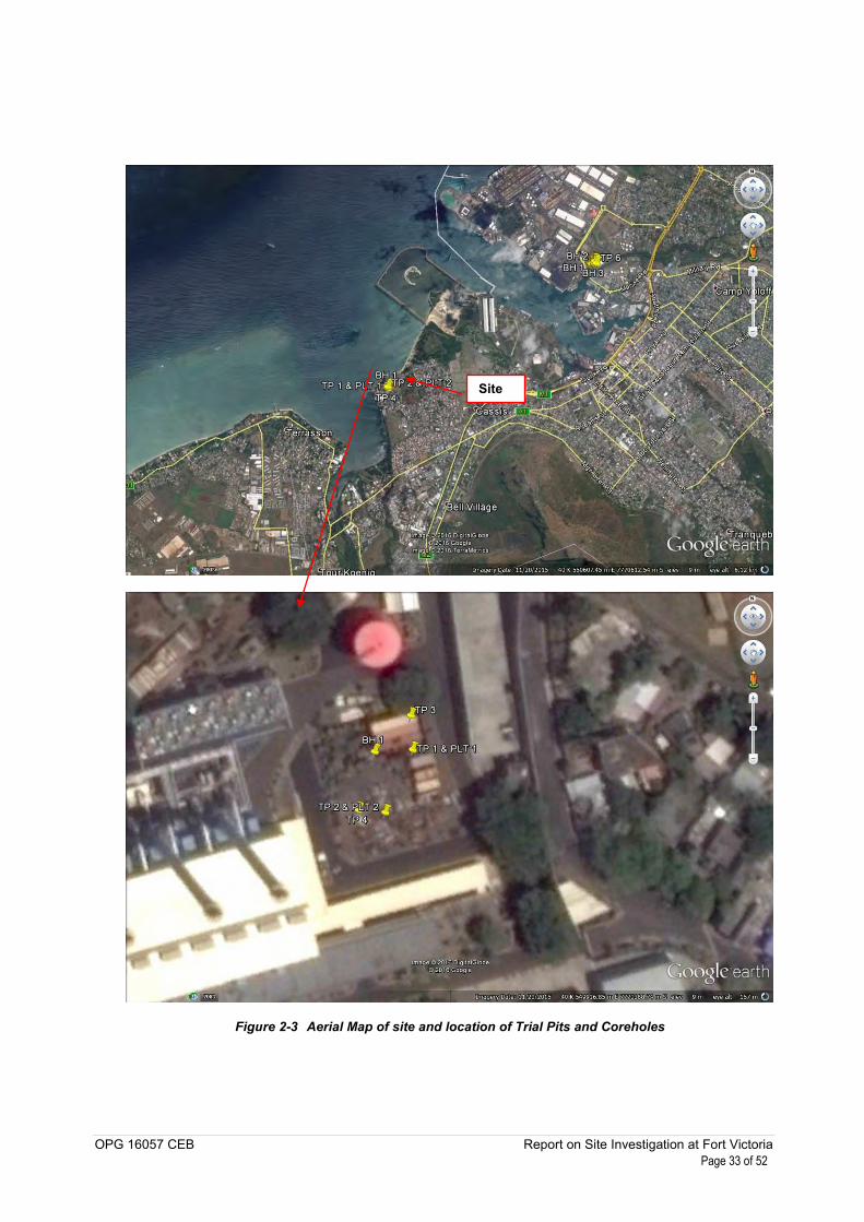
Figure 2-3 Aerial Map of site and location of Trial Pits and Coreholes .................................................................... 33
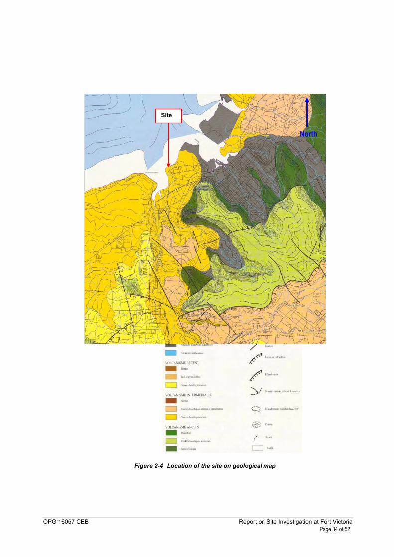
Figure 2-4 Location of the site on geological map ............................................................................................................. 34
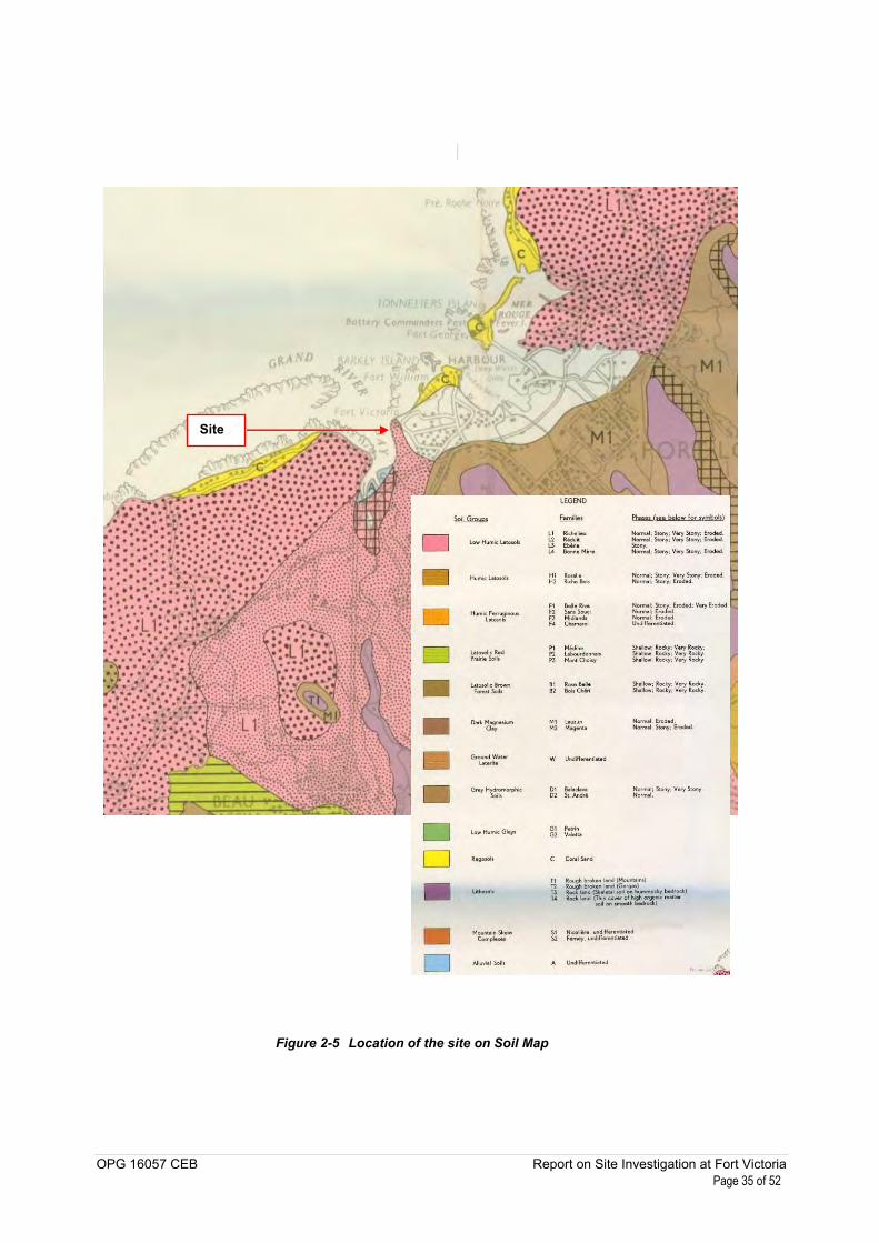
Figure 2-5 Location of the site on Soil Map ........................................................................................................................... 35
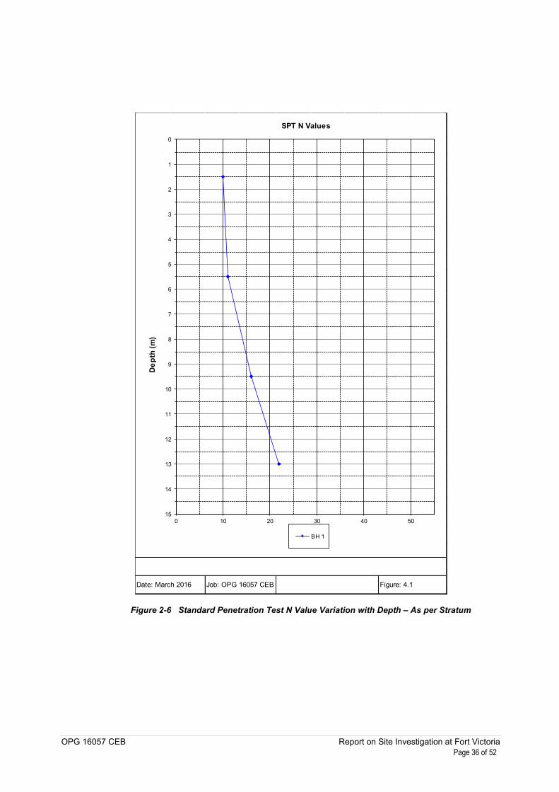
Figure 2-6 Standard Penetration Test N Value Variation with Depth – As per Stratum .................................... 36
Figure 2-7 Rock Quality Designation Variation with Depth ........................................................................................... 37
Figure 2-8 A Line Plasticity Chart .............................................................................................................................................. 38
OPG 16057 CEB Geotechnical Investigations at Fort Victoria Page 7 of 52
Introduction
On 7th January 2016, the Central Electricity Board (CEB) awarded Water Research Co Limited (Water
Research) a contract (Ref. Q18298) to carry out geotechnical investigations at Fort Victoria power station, in the
district of Port Louis. The geotechnical investigation aimed to support the design and construction of a
proposed 6,500m3 heavy fuel oil tank (approximate diameter 23m & height 14m) and ancillary infrastructures.
Appendix A depicts the proposed layout of the tank and the site.
Water Research’s brief comprised the following items:
Formation of 4No. trial pits
Drilling 1No.rotary coring borehole
Soil and rock sampling. Undisturbed soil samples were 50mm diameter U2 samplers. Rock cores
were 52mm diameter. Disturbed samples included large and small bulks
Compaction, compressibility, strength and chemical laboratory tests
Report on findings and general geotechnical evaluation.
This Report is presented in the following format:
Desk study information for the site, including geological maps and plans
Factual information comprising: description of fieldwork and exploratory hole logs
Geotechnical assessment comprising: profile definition; discussion on geotechnical parameters for
foundation design; recommendations for selection of foundation solutions; general foundation
comments including bearing capacity and settlements.
OPG 16057 CEB Geotechnical Investigations at Fort Victoria Page 8 of 52
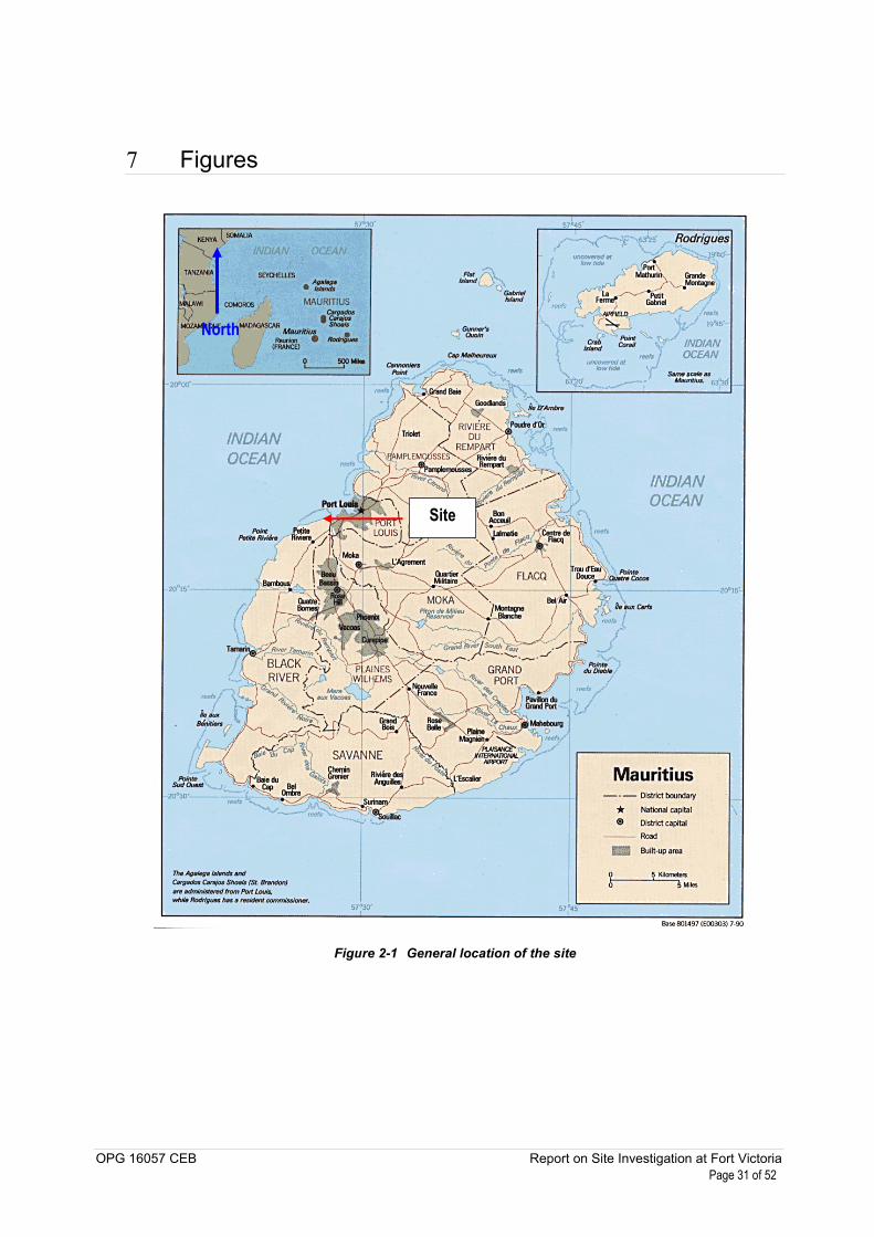
Desk study information
2.1 Site location and topography
The subject site is situated within the Fort Victoria power station, in the locality of Bain des Dames (Figures 2.1
to 2.3). The site lies on the shoreline of the western coast and is surrounded by residential dwellings. Bain des
Dames public beach adjoins the site to the north west. The site can be accessed from Cassis Road which
branches off the M1 motorway.
The site is an operational power station which comprises of existing tanks and heavy engines. The investigated
area is on a strip of land in the western portion of the power station. The area was being used as a storage spot
with scrap metals and other heavy duty materials. According to the Client there used to be a trench crossing the
site after which it was backfilled.
The site elevations generally vary between 2m and 5m amsl. The site is flat with no salient topographical
feature. Surface water run-off is expected to be channelled towards the ocean.
2.2 Published geology
According to the Carte Geologique au 1:50,000 of Mauritius, the site is underlain by fresh basalt of the
Intermediate volcanic series (Figure 2.4, Ref. 1). The intermediate volcanic series are composed of basaltic
flows overlying basalt agglomerate. The basalts are not very homogeneous in composition but, on the whole,
they are made up of fine grained olivine rocks, grey to black in colour. The very compact types are rather rare,
and are in general porous and often vesicular, the vesicles being sometimes infilled with a powdery bluish
material. They are also slightly fissured and in some places the fissures and cavities are filled with light cream
coloured clay (Ref. 2).
According to the Soil Map of Mauritius (Figure 2.5, Ref. 3) the natural strata on the site area consists of Low
Humic Latosols. These soils occur in the sub-humid and lower rainfall zones from 1,000mm to 2,750mm
annually, in areas with a distinct dry season. They are deep (+100cm) to moderately deep soils (+60cm) with
good internal drainage. They have a weak to moderately strong structured A horizon varying from red to brown
in colour over a red to reddish brown B horizon. The texture of the A horizon is silty clay to clay; kaolinite is the
dominant clay mineral (Ref. 2).
OPG 16057 CEB Geotechnical Investigations at Fort Victoria Page 9 of 52
Field and laboratory works
3.1 Geotechnical investigation works
The scope of fieldworks was specified in the Tender Document and was undertaken in general accordance with
BS 5930 (1999) (Ref. 4). The site works were carried out between the 2nd and 23rd February 2016. The location
of the Trial Pits and Corehole are shown in Appendix A; the photographs of the site activities are presented in
Appendix B. The following sections present a general description of the works carried out.
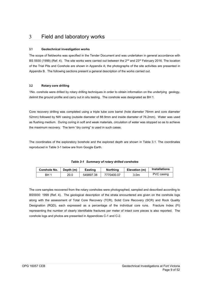
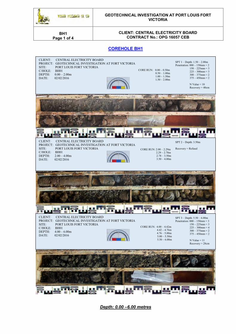
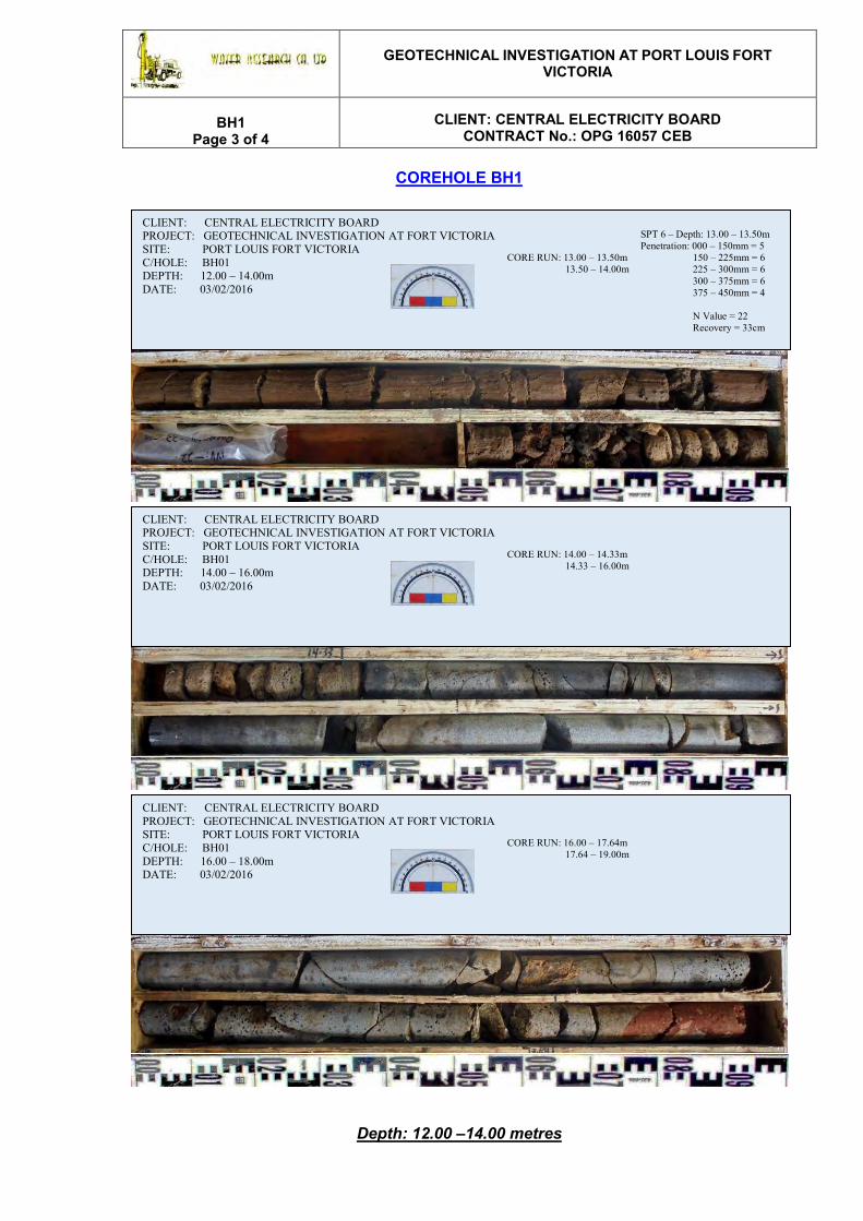
3.2 Rotary core drilling
1No. corehole were drilled by rotary drilling techniques in order to obtain information on the underlying geology,
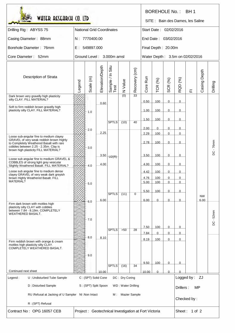
delimit the ground profile and carry out in situ testing. The corehole was designated as BH 1.
Core recovery drilling was completed using a triple tube core barrel (hole diameter 76mm and core diameter
52mm) followed by NW casing (outside diameter of 88.9mm and inside diameter of 76.2mm). Water was used
as flushing medium. During coring in soft and weak materials, circulation of water was stopped so as to achieve
the maximum recovery. The term “dry coring” is used in such cases.
The coordinates of the exploratory borehole and the explored depth are shown in Table 3.1. The coordinates
reproduced in Table 3-1 below are from Google Earth.
Table 3-1 Summary of rotary drilled coreholes
Corehole No. Depth (m) Easting Northing Elevation (m) Installations
BH 1 20.0 549897.38 7770400.07 3.0m PVC casing
The core samples recovered from the rotary coreholes were photographed, sampled and described according to
BS5930: 1999 (Ref. 4). The geological description of the strata encountered are given on the corehole logs
along with the assessment of Total Core Recovery (TCR), Solid Core Recovery (SCR) and Rock Quality
Designation (RQD), each expressed as a percentage of the individual core runs. Fracture Index (FI)
representing the number of clearly identifiable fractures per meter of intact core pieces is also reported. The
corehole logs and photos are presented in Appendices C-1 and C-2.

OPG 16057 CEB Geotechnical Investigations at Fort Victoria Page 10 of 52
3.3 Trial Pits
4No. Trial Pits were excavated using a JCB 4CX mechanical backhoe excavator at the locations and depths shown in Table 3-2. Small and large bulk disturbed samples were taken at regular intervals where possible for
geotechnical, chemical and contamination testing – the list of samples taken are presented in Table 3-2. The
logs and photos of the Trial Pits are presented in Appendices C-3 and C-4, respectively. The coordinates reproduced in Table 3-2 are from Google Earth. Trial Pits TP 1 and 2 were left open for three weeks in order to
observe the potential presence of groundwater. After 3 weeks, black petroleum like based product was
observed at the base and along the walls of trial pit TP 2 on 23rd February 2016.
Table 3-2 Summary of Trial Pits
TP No. Depth
(m)
Samples Intervals
Easting (UTM)
Northing (UTM)
Elevation (m)
TP 1 2.55 0.5 – 1.0;
1.0 – 1.5 549914 7770411 3.0
TP 2 1.90 0.0 – 0.5;
1.0 – 1.5 549909 7770382 3.0
TP 3 1.5 0.3 ; 1.0 549907 7770409 3.0
TP 4 1.1 0.2 ; 0.7 549892 7770385 3.0
3.4 In Situ Tests
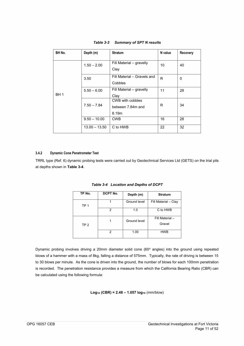
3.4.1 Standard Penetration Tests
6No. of Standard penetration tests (SPT) were carried out in cohesive and granular soils in accordance with
BS1377: Part 9 (1990) (Ref. 5). The test consisted of driving a 50mm split spoon by means of a 63.5kg hammer
falling a height of 760mm. The SPT blow count N is the number of blows required to drive the spoon by 300mm
after initially seating the spoon by 150mm. Tests for which the full penetration of 450mm could not be achieved after 50 blows are termed as “Refusals”. Table 3-3 shows a summary of the SPT test results.
OPG 16057 CEB Geotechnical Investigations at Fort Victoria Page 11 of 52
Table 3-3 Summary of SPT N results
BH No. Depth (m) Stratum N value Recovery
BH 1
1.50 – 2.00 Fill Material – gravelly
Clay 10 40
3.50 Fill Material – Gravels and
Cobbles R 0
5.50 – 6.00 Fill Material – gravelly
Clay 11 28
7.50 – 7.84 CWB with cobbles
between 7.84m and
8.19m
R 34
9.50 – 10.00 CWB 16 28
13.00 – 13.50 C to HWB 22 32
3.4.2 Dynamic Cone Penetrometer Test
TRRL type (Ref. 6) dynamic probing tests were carried out by Geotechnical Services Ltd (GETS) on the trial pits at depths shown in Table 3-4.
Table 3-4 Location and Depths of DCPT
TP No. DCPT No. Depth (m) Stratum
TP 1 1 Ground level Fill Material – Clay
2 1.0 C to HWB
TP 2 1 Ground level
Fill Material –
Gravel
2 1.00 HWB
Dynamic probing involves driving a 20mm diameter solid cone (60o angles) into the ground using repeated
blows of a hammer with a mass of 8kg, falling a distance of 575mm. Typically, the rate of driving is between 15
to 30 blows per minute. As the cone is driven into the ground, the number of blows for each 100mm penetration
is recorded. The penetration resistance provides a measure from which the California Bearing Ratio (CBR) can
be calculated using the following formula:
Log10 (CBR) = 2.48 – 1.057 log10 (mm/blow)
OPG 16057 CEB Geotechnical Investigations at Fort Victoria Page 12 of 52
The details of the tests, the penetration vs blows and CBR results are presented in Appendix D-1. The existing
asphalt and concrete road surfaces at the location of the tests were removed previous to the execution of the
tests.
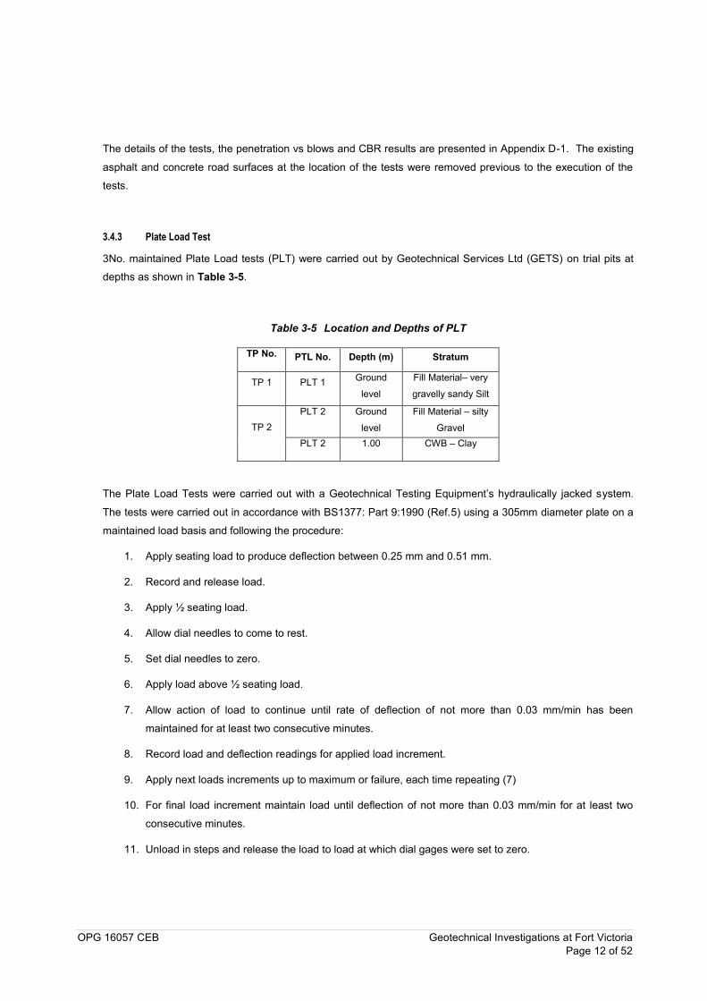
3.4.3 Plate Load Test
3No. maintained Plate Load tests (PLT) were carried out by Geotechnical Services Ltd (GETS) on trial pits at
depths as shown in Table 3-5.
Table 3-5 Location and Depths of PLT
TP No. PTL No. Depth (m) Stratum
TP 1 PLT 1 Ground
level
Fill Material– very
gravelly sandy Silt
TP 2 PLT 2 Ground
level
Fill Material – silty
Gravel PLT 2 1.00 CWB – Clay
The Plate Load Tests were carried out with a Geotechnical Testing Equipment’s hydraulically jacked system.
The tests were carried out in accordance with BS1377: Part 9:1990 (Ref.5) using a 305mm diameter plate on a
maintained load basis and following the procedure:
1. Apply seating load to produce deflection between 0.25 mm and 0.51 mm.
2. Record and release load.
3. Apply ½ seating load.
4. Allow dial needles to come to rest.
5. Set dial needles to zero.
6. Apply load above ½ seating load.
7. Allow action of load to continue until rate of deflection of not more than 0.03 mm/min has been
maintained for at least two consecutive minutes.
8. Record load and deflection readings for applied load increment.
9. Apply next loads increments up to maximum or failure, each time repeating (7)
10. For final load increment maintain load until deflection of not more than 0.03 mm/min for at least two
consecutive minutes.
11. Unload in steps and release the load to load at which dial gages were set to zero.
OPG 16057 CEB Geotechnical Investigations at Fort Victoria Page 13 of 52
The complete set of results and the load displacement curves are presented in Appendix D-2.
3.5 Laboratory testing
The laboratory schedule was prepared as stipulated in the tender document and shown in Appendix E. The
laboratory testing aimed at determining site parameters concerning the classification, chemical and strength
properties of the strata to enable geotechnical design. The programme of laboratory testing was carried out in
accordance with BS1377 (1990) (Ref. 5) at the Geotechnical Services (GETS), University of Mauritius
Laboratories and Alcontrol (England) for contaminants testing. The test schedules included:
Natural Moisture Content Determinations
Particle Size Distribution (wet sieving and hydrometer)
Atterberg Limits
Bulk and Dry Density Test
Chloride and Sulphate Content Determination
Organic Matter Content Determination
Unconfined Compression Test on rock cores
Contamination Testing: As, Cd, Cr, Cu, Ni, Zn, Pb, Hg, Se, B, hex Chromium, total cyanide, free
cyanide, total sulphate, sulphide, total sulphur, pH, speciated (16), PAHs, Phenols. Thiocyanate, TPH
(Total Petroleum Hydrocarbons)
The soil and rock tests and the relevant standards for performing the tests are presented in Table 3-6. The list
of scheduled and completed laboratory tests is presented in Appendix E.
Table 3-6 Standards for laboratory tests
Test Standard Moisture content BS1377: Part 2.
Liquid Limit (LL) and Plastic Limit (PL) BS 1377: Part 2, Clauses 4.3 and 5.3
Particle size distribution BS 1377: Part 2. Bulk Density Determination BS1377:Part 2 Loss on Ignition BS 1377: Part 3: 1990 clause 4, test 3
Total sulphate content determination test BS 1377: Part 3: 1990, test 5
OPG 16057 CEB Geotechnical Investigations at Fort Victoria Page 14 of 52
Test Standard
Water soluble chloride content determination test BS1377: Part 3: 1990, test 7.2
Uniaxial Rock Compressive Strength & Density of rock
ISRM suggested Methods for Rock Characterisation, Testing and Monitoring – Standard Methods for Determining the Uniaxial Compressive Strength and Deformability of Rock Materials - 1979
Contamination Testing Methods and standards are given in Appendix F
A summary of the laboratory test results is presented in Table 3-7 and Table 3-7 below.
OPG 16057 CEB Geotechnical Investigations at Fort Victoria Page 15 of 52
Table 3-7 Summary of Laboratory Testing Results on clayey material
TP/BH No.
Depth (m) Stratum Moisture
Content (%) Loss on Ignition
Bulk Unit
Weight (Mg/cm3)
Atterberg Limits PSD (%)
Total Sulphate Content
(%)
Chloride Content (%)
Liquid Limit
LL
Plastic Limit PL
Plasticity Index PI
Gravel Sand Silt Clay
TP 1 0.5 – 1.0 Clay (Fill Material) 21.3 11 62.5 32.3 30.2 - - - - 0.05 0.03
TP 1 1.5 – 2.0 C to HWB 26.1 10 1.56 59.6 33.1 26.4 40 18.7 23.3 18 - -
TP 2 0.0 – 1.0 Gravel (Fill
Material) 11.5
- 1.67 57.2 29.9 27.3 66 11.8 11.7 10.5 0.07 0.07
TP 2 1.0 – 1.5 H to MWB 26.7 -
- 47.6 24.3 23.3 - - -- - - -

OPG 16057 CEB Geotechnical Investigations at Fort Victoria Page 16 of 52
Table 3-8 Summary of Laboratory Testing Results on Rock Cores
TP/BH No. Stratum Depth (m) Unconfined Compressive
Strength / MPa (N/mm2)
BH 1 SWB 14.83 – 15.00 53.5
BH 1 SWB 16.28 – 16.53 38.7
BH 1 SWB 16.86 – 17.00 18.3
BH 1 MWB 18.24 – 18.38 3.6
OPG 16057 CEB Geotechnical Investigations at Fort Victoria Page 17 of 52
Results and ground conditions
4.1 Identified soil profile
The depth and thickness of the various strata observed in the Trial Pits and Corehole are shown in the logs and are summarised in Table 4-1.
Table 4-1 Summary of strata encountered in metres
TP / BH No.
Strata Topsoil / Fill
Material C to HWB M WB SWB
TP 1 0.00 – 1.15
(gravelly Clay) 1.15 – 2.55
TP 2 0.00 – 0.60
(Gravel) 0.6 – 1.9 (HWB)
TP 3 0.00 – 0.9 (Silty &
Clay) 0.9 – 1.5
TP 4 0.00 – 0.80
(Gravel and Clay) 0.80 – 1.10
BH 1
0.00 – 2.25 (Clay)
2.25 – 6.0 (clayey
Gravel & Cobbles)
6.00 – 10.0 (CWB)
10.0 – 13.5
13.53 – 14.33
17.64 – 20.0 14.33 – 17.64
The following definitions were considered for weathered basalts:
Residual Soil: No recognisable rock texture. Surface layer contains humus and plant roots.
Completely Weathered (CW) basalt: Rock completely decomposed by weathering in place but texture
still recognisable. Can be excavated by hand.
Highly Weathered (HW) basalt: Rock so weakened by weathering that fairly large pieces can be
broken and crumbled in the hands. Sometimes recovered as core in careful rotary drilling.
Moderately Weathered (MW) basalt: Considerable weathered throughout. Possessing some strength
– large pieces cannot be broken by hand, reasonable core recovery. Often limonite stained. Difficult
to rip.
OPG 16057 CEB Report on Site Investigation at Fort Victoria Page 18 of 52
Slightly Weathered (SW) basalt: Distinctly weathered through much of the rock fabric with slight
limonite staining. Strength approaches that of the fresh rock. Requires explosive for excavation.
Highly permeable open joints.
The following sections summarise the descriptions for each of the encountered strata.
4.1.1 Topsoil and Fill Material
Topsoil was observed from the ground level to a maximum depth of 0.6m bgl. The Topsoil were represented by
compacted Clay, Silt and Gravel.
Fill Material was encountered on all Trial Pits and the Corehole generally as from the surface or below the
Topsoil to an average depth of 1.0m. It is likely that the Fill Material has been placed all over the site. For the
corehole, the depth of the Fill Material was difficult to ascertain and it is presumed to extend to 6.0m bgl. The
spatial distribution of the suspected 6m Fill Material identified at BH 1 could not be defined due to restricted
mobility on site. The trial pits and plate load tests trenches did not provide further evidence of the 6m thick Fill.
It is possible that this thickness of Fill Material is localised or sporadically spread across the northern portion of
the proposed tank outline. Two excavations done in close proximity of the borehole proved Fill Material up to
1.15m depth.
The encountered Fill Material was described as:
Soft to firm dark brown to reddish brown very gravelly high plasticity Clay / Silt with frequent fragments
of glasses and plastics. In the corehole the Clay Fill is limited to the upper 2.25m.
Loose sub-angular medium to coarse Gravel and Cobbles of strong light grey Slightly Weathered
Basalt.
2No. SPT tests were carried out on the clayey fill material and the measured of SPT N-values of 10 and 11
(Figure 4.1). 1No. SPT tests performed on Gravel and Cobbles (fill material) reported refusal.
4.1.2 Clayey Weathered Basalts
Completely and Completely to Highly Weathered Basalts were encountered on all exploratory holes except on
TP2. This strata was intercepted across the site from a depth of 0.80m to 13.5m bgl with an average thickness
of 2.0m. The strata were generally described as firm to stiff reddish brown to dark brown high plasticity Clay.
2No. SPT tests were carried out on the Completely to Highly Weathered Basalts and the measured SPT N-
values were 11 and 16 (Figure 4.1).

OPG 16057 CEB Report on Site Investigation at Fort Victoria Page 19 of 52
4.1.3 Rock Weathered Basalt
Highly Weathered Basalt was retrieved at trial pit TP 2 between 0.6 and 1.9m. This layer was logged as
moderately weak orangish brownish grey with black discolorations at joints highly vesicular with frequent
amygdales. The joints are infilled with yellowish brown medium plasticity Clay.
Moderately Weathered Basalt (MWB) was encountered at BH 1 at alternating depths between 13.53m to 20.0m
bgl. The average thickness of the stratum is 2.0m and was described as weak to moderately strong grey with
black and yellow mottles vesicular with frequent amygdales very closely jointed. RQD values for the MWB
generally varies between 0% and 16 (Figure 4.2). Unconfined Compressive Strength (UCS) test carried out on a
Moderately Weathered core returned a value of 3.6MPa.
Slightly Weathered (SWB) was encountered between 14.33m to 17.64m and was generally described as strong
to moderately grey vesicular closely to medium jointed. RQD values for the MWB generally varies between 34%
and 61 (Figure 4.2). Unconfined Compressive Strength (UCS) test carried out on the strata returned values
varying between 18MPa and 54MPa.
4.2 Groundwater
Groundwater was encountered only at corehole BH 1 at3.5m bgl measured on 23rd February 2016.
4.3 Dynamic Cone Penetration Test Results
A summary of the DCPT results is presented in Table 4-2.
Table 4-2 Summary of DCPT Results
TP No. DCPT No. Depth (m) Stratum CBR
TP 1 1 Ground
level
Fill Material –
Clay 10
2 1.0 C to HWB 20
TP 2 1 Ground
level
Fill Material –
Gravel 34
2 1.00 HWB 21
OPG 16057 CEB Report on Site Investigation at Fort Victoria Page 20 of 52
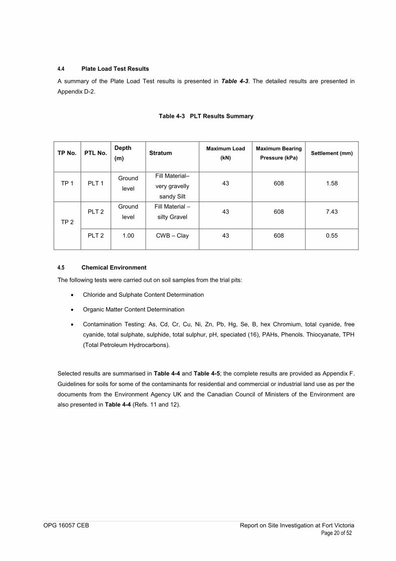
4.4 Plate Load Test Results
A summary of the Plate Load Test results is presented in Table 4-3. The detailed results are presented in
Appendix D-2.
Table 4-3 PLT Results Summary
TP No. PTL No. Depth (m)
Stratum Maximum Load
(kN) Maximum Bearing
Pressure (kPa) Settlement (mm)
TP 1 PLT 1 Ground
level
Fill Material–
very gravelly
sandy Silt
43 608 1.58
TP 2
PLT 2 Ground
level
Fill Material –
silty Gravel 43 608 7.43
PLT 2 1.00 CWB – Clay 43 608 0.55
4.5 Chemical Environment
The following tests were carried out on soil samples from the trial pits:
Chloride and Sulphate Content Determination
Organic Matter Content Determination
Contamination Testing: As, Cd, Cr, Cu, Ni, Zn, Pb, Hg, Se, B, hex Chromium, total cyanide, free
cyanide, total sulphate, sulphide, total sulphur, pH, speciated (16), PAHs, Phenols. Thiocyanate, TPH
(Total Petroleum Hydrocarbons).
Selected results are summarised in Table 4-4 and Table 4-5; the complete results are provided as Appendix F.
Guidelines for soils for some of the contaminants for residential and commercial or industrial land use as per the
documents from the Environment Agency UK and the Canadian Council of Ministers of the Environment are also presented in Table 4-4 (Refs. 11 and 12).

OPG 16057 CEB Report on Site Investigation at Fort Victoria Page 21 of 52
Table 4-4 Soil Chemical Tests Summary
Parameter Units Limit of
Detection (LOD)
Soil Results Range
Soil guideline value
(residential) mg/kg
Soil guideline value
(commercial) mg/kg
Chloride % <0.01 0.03 – 0.07
Sulphate % <0.01 0.03 – 0.07
Organic Matter % <0.1 10 - 11
Arsenic, As mg/kg <0.6 <6 - 32 32 640
Cadmium, Cd mg/kg <0.02 <0.2 – 2.29 10 230
Chromium, Cr mg/kg <0.9 86.3 - 271 67 87
Copper, Cu mg/kg <1.4 91.1 - 355 63 91
Nickel, Ni mg/kg <0.2 128 - 407 130 1,800
Zinc, Zn mg/kg <1.9 83.5 – 2370 200 360
Lead, Pb mg/kg <0.7 23.9 - 2850 140 600
Mercury, Hg mg/kg <0.14 <1.4 – 1.56 1 50
Selenium, Se mg/kg <1 <10 350 13,000
Boron, B mg/kg <0.7 10.2 – 30.4
Hexavalent Chromium mg/kg <0.6 <0.6 0.4 1.4
Total Cyanide mg/kg <1 <1
Free Cyanide mg/kg <1 <1 0.9 8
Total Sulphate mg/kg <48 104 - 2740
Sulphide mg/kg <15 <15
Total Sulphur % <0.02 <0.02 – 0.161
pH pH units 1 8.61 – 9.26 6 - 8 6 - 8
Speciated (16), PAHs μg/kg <118 <118 - 6750
Phenols (Total detected
monohydric) mg/kg <0.035 <0.035 3.8 3.8
Thiocyanate mg/kg <1 <1
TPH (Total Petroleum
Hydrocarbons) mg/kg <10 <10 – 68.9
Phenols mg/kg <0.01 <0.01 420 3200

OPG 16057 CEB Report on Site Investigation at Fort Victoria Page 22 of 52
Cresols mg/kg <0.01 <0.01
Xylenols mg/kg <0.015 <0.015 2.4 2.4
Table 4-5 Water Chemical Tests Summary
Parameter Units Limit of
Detection (LOD)
Water Results
Arsenic, As µg/L <0.12 0.405
Cadmium, Cd µg/L <0.1 <0.1
Chromium, Cr µg/L <0.22 5.32
Copper, Cu µg/L <0.85 1.4
Nickel, Ni µg/L <0.15 1.93
Zinc, Zn µg/L <0.41 5.15
Lead, Pb µg/L <0.02 0.174
Mercury, Hg µg/L <0.01 <0.01
Selenium, Se µg/L <0.39 0.96
Boron, B µg/L <9.4 250
Hexavalent Chromium mg/L <0.03 <0.03
Total Cyanide mg/L <0.05 <0.05
Free Cyanide mg/L <0.05 <0.05
Sulphate mg/L <2 33.9
Total (16), PAHs μg/L <0.344 0.344
Phenols (Total detected monohydric) mg/L <0.016 <0.016
TPH (Total Petroleum Hydrocarbons) μg/L <100 3020
Phenols mg/L <0.002 <0.002
Cresols mg/L <0.006 0.006

OPG 16057 CEB Report on Site Investigation at Fort Victoria Page 23 of 52
Geotechnical engineering assessment
This Chapter presents geotechnical evaluation and recommendations for the proposed development based on
the interpreted ground conditions. As stated in Section 1.1, the proposed development consists of a 6,500m3
tank with a diameter of 24m for heavy oil storage. A full tank with its combined load is expected to exert of
pressure of 145 kPa. This pressure was estimated by assuming a 14m high tank storing fuel oil with a density of
10kN/m3. The value of the fuel density was provided by the Client.
The geotechnical issues discussed are: design soil profile and parameters and discussion on foundation
solutions. Shallow or deep foundations may in principle be adequate to support the proposed development
under assessment. Engineering Fill has to be used for the case of shallow foundation due to the presence of
Fill Material.
5.1 Identified Soil Profile
The profile at the site, in order of vertical sequence, consists of i) 1m of Fill Material, ii) 12.5m of Clay
(Completely to Highly Weathered Basalt), and iii) Moderately to Slightly Weathered Basalts. Geological profiles
across the corehole and Trial Pits are presented in Appendix C-5. Groundwater prevailed as from a depth of
3.5m.
The presumed thickness of the Fill Material encountered in the corehole is 6m. If this thickness of Fill Material is
localised, it is recommended that the fill material is replaced by engineered fill, however for the case for which
the distribution is relatively widespread, the following scenario will be assessed i) i) 6m of Fill Material, ii) 7.5m
of Clay (Completely to Highly Weathered Basalt), and iii) Moderately to Slightly Weathered Basalts.
The following sections describe the geotechnical properties associated with the encountered strata. Fill Material
should be avoided as founding stratum or for engineering purposes as far as possible.
5.1.1 Properties of Fill Material
The clayey silty Gravel was generally described as loose and the following properties can be considered for
analysis:
Soil unit weight of 18kN/m3.
SPT N values for the clayey Gravel varied between 10 and 11 (Figure 4.1).
Assuming SPT N Value of 10, an angle of shearing resistance of 29o can be used for analysis (Ref. 4).
Relative Density 20%-40%

OPG 16057 CEB Report on Site Investigation at Fort Victoria Page 24 of 52
5.1.2 Clayey Weathered Basalts
The clayey weathered basalt layer is composed of firm high plasticity silty Clay. The following properties are
suggested for geotechnical analysis based on the laboratory test results and correlations:
Soil Unit Weight of 15kN/m3.
Average Natural moisture contents of 26%.
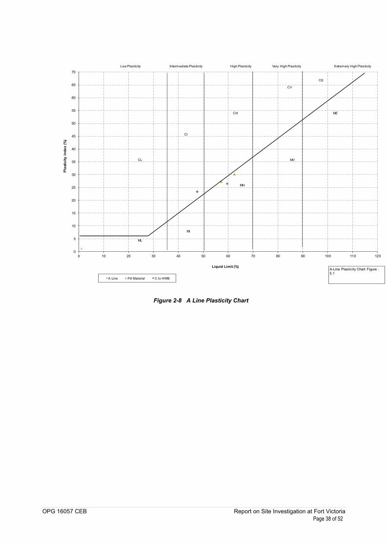
Atterberg Limits indicate the stratum to be silt/clay of high plasticity with average Plasticity Index of 30
(Figure 5.1). The variation of the moisture content and the liquid and plastic limits are presented in
Figure 5.2.
The representative SPT blow count (N) is 16 (Figure 4.1). Based on the SPT N correlation to undrained
shear strength (Su) (Ref. 7), Plasticity Index (PI) of 42 and f1 value of 4.5 the estimated Su value
would be 72kPa. Typical values for firm clay material are between 40kPa and 75kPa. An undrained
shear strength (Su) of 65kPa will be adopted for analysis.
mv can be determined using Stroud’s correlation (Ref. 8) mv= 1 / f2N; where f2 can be defined based
on PI as 0.45, and SPT = 16. Thus mv for the material is in the order of 0.13m2/MN corresponding to a
medium compressibility material.
Sulphate Content of the soil is 0.03% and average Chloride Content is 0.04%.
5.1.3 Moderately and Slightly Weathered Basalt
The following properties can be considered representative of the M to SWB basalt rock:
Bulk unit weight of 22kN/m3.
M to SWB rock was described as moderately strong to strong; UCS values corresponding to this
description varies between 12.5MPa and 50MPa.
Unconfined Compression tests on rock cores at depths varying between 14.83m and 18.38m gave
UCS values varying between 3.6MPa and 53.5MPa.
Rock Quality Designation (RQD) values for rock encountered at shallow depths (between 13.55m and
20.0m) vary between 0 and 61 indicating rock of very poor to fair quality rock (Figures 4.2 and 4.3).
5.1.4 Engineering Fill
The following properties for the granular engineering fill to be placed on site are suggested for analysis:
Achieved soil unit weight of 20kN/m3.
For the granular fill (assumed as a dense gravel), a value of SPT N of 30 can be considered.
A conservative an angle of shearing resistance of 32o can be used for design.
Relative Density 40%-60%

OPG 16057 CEB Report on Site Investigation at Fort Victoria Page 25 of 52
5.2 Foundation options
For economic and practical reasons, shallow foundations are the conventional solution for founding structures.
Deep foundations or alternative solutions (e.g. ground improvement) are implemented for low bearing capacity
or high compressibility strata, subjected to loadings that can result on ultimate or serviceability performance
limitations.
The selection of the foundation solution will be controlled by the loads imposed and the response of the ground
profile. The proposed development includes a 14m high heavy fuel tank with a stress magnitude of 145kPa. It is
recommended that the Fill Material is excavated and replaced by Engineering Fill. For the purpose of analysis it
is assumed that the 2m of the on-site materials are to be replaced by Engineering Fill. Therefore the
Engineering Fill may act as founding layer.
The following analyses are focused on evaluating the bearing capacity and related settlements for the proposed
tank at a foundation depth of 0.6m bgl for a 24m circular raft. Two (2No) profile scenarios are analysed to verify
the shallow foundation behaviour. This will provide a reliable indication of the potential bearing capacity and
settlement threshold of the prevailing stratum. The bearing capacities are computed assuming no eccentric or
inclined loading and without considering sloping ground.
A pile foundation solution shall be implemented in the case that the settlement or bearing capacity for shallow
foundation solutions are inadequate. Piles may be founded on the Moderately to Slightly Weathered
encountered generally at 14.5m bgl.
5.3 Bearing capacity and settlement for Engineering Fill on natural strata (Scenario 1)
In this case a layer of 2.0m thick dense granular Engineering Fill is underlain by a 12.5m thick of clayey
weathered basalt (Plate 1).
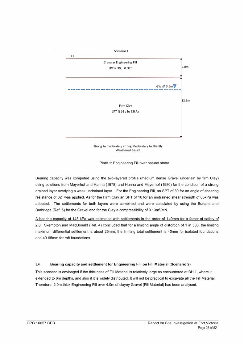
OPG 16057 CEB Report on Site Investigation at Fort Victoria Page 26 of 52
GL
GW @ 3.5m
12.5m
2.0m
Firm Clay
SPT N 16 ; Su 65kPa
Strong to moderately strong Moderately to Slightly Weathered Basalt
Granular Engineering Fill
SPT N 30 ; Ф 32°
Scenario 1
Plate 1: Engineering Fill over natural strata
Bearing capacity was computed using the two-layered profile (medium dense Gravel underlain by firm Clay)
using solutions from Meyerhof and Hanna (1978) and Hanna and Meyerhof (1980) for the condition of a strong
drained layer overlying a weak undrained layer. For the Engineering Fill, an SPT of 30 for an angle of shearing
resistance of 32º was applied. As for the Firm Clay an SPT of 16 for an undrained shear strength of 65kPa was
adopted. The settlements for both layers were combined and were calculated by using the Burland and
Burbridge (Ref. 5) for the Gravel and for the Clay a compressibility of 0.13m2/MN.
A bearing capacity of 148 kPa was estimated with settlements in the order of 140mm for a factor of safety of
2.8. Skempton and MacDonald (Ref. 4) concluded that for a limiting angle of distortion of 1 in 500, the limiting
maximum differential settlement is about 25mm, the limiting total settlement is 40mm for isolated foundations
and 40-65mm for raft foundations.
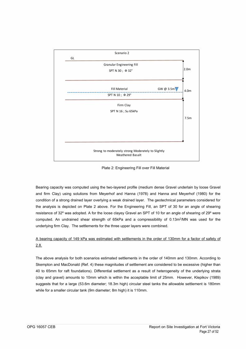
5.4 Bearing capacity and settlement for Engineering Fill on Fill Material (Scenario 2)
This scenario is envisaged if the thickness of Fill Material is relatively large as encountered at BH 1, where it
extended to 6m depths, and also if it is widely distributed. It will not be practical to excavate all the Fill Material.
Therefore, 2.0m thick Engineering Fill over 4.0m of clayey Gravel (Fill Material) has been analysed.
OPG 16057 CEB Report on Site Investigation at Fort Victoria Page 27 of 52
GL
GW @ 3.5m
7.5m
2.0m
Firm Clay
SPT N 16 ; Su 65kPa
Strong to moderately strong Moderately to Slightly Weathered Basalt
Granular Engineering Fill
SPT N 30 ; Ф 32°
Scenario 2
Fill Material
SPT N 10 ; Ф 29°4.0m
Plate 2: Engineering Fill over Fill Material
Bearing capacity was computed using the two-layered profile (medium dense Gravel underlain by loose Gravel
and firm Clay) using solutions from Meyerhof and Hanna (1978) and Hanna and Meyerhof (1980) for the
condition of a strong drained layer overlying a weak drained layer. The geotechnical parameters considered for
the analysis is depicted on Plate 2 above. For the Engineering Fill, an SPT of 30 for an angle of shearing
resistance of 32º was adopted. A for the loose clayey Gravel an SPT of 10 for an angle of shearing of 29º were
computed. An undrained shear strength of 65kPa and a compressibility of 0.13m2/MN was used for the
underlying firm Clay. The settlements for the three upper layers were combined.
A bearing capacity of 149 kPa was estimated with settlements in the order of 130mm for a factor of safety of
2.8.
The above analysis for both scenarios estimated settlements in the order of 140mm and 130mm. According to
Skempton and MacDonald (Ref. 4) these magnitudes of settlement are considered to be excessive (higher than
40 to 65mm for raft foundations). Differential settlement as a result of heterogeneity of the underlying strata
(clay and gravel) amounts to 10mm which is within the acceptable limit of 25mm. However, Klepikov (1989)
suggests that for a large (53.6m diameter; 18.3m high) circular steel tanks the allowable settlement is 180mm
while for a smaller circular tank (9m diameter; 8m high) it is 110mm.
OPG 16057 CEB Report on Site Investigation at Fort Victoria Page 28 of 52
Ground improvement can be performed to improve the existing sub surface ground via mechanical methods.
These methods can include dynamic compaction, stone columns and soil cement columns. This would increase
bearing capacity and reduce settlements.
If shallow foundations solutions are implemented, the tank is expected to sink uniformly due to the uniformly
circular distributed load. The sinking of the tank is due to serviceability load and according to Klepikov (1989)
the magnitudes of settlement (maximum of 140mm) may be considered as acceptable. Settlements may be
curtailed by reducing the designed height of the tank.
The settlements can be mitigated by using piles as foundation solution by transferring the load to the competent
stratum at a depth of 14.0m. Piles will also significantly increase the allowable bearing capacity. Pile foundations
are expected to cost more than shallow foundations.
5.5 Deep foundations
Selection of type of pile depend on stress applied construction constraints and availability in Mauritius; based
on these criteria, driven precast piles may be implemented. Although, if the scrap metals are cleared, there is
no foreseeable constraints on the site which can hamper mobility. Other types of piles may be suggested by the
piling suppliers. Vibration associated with pilling works should be regulated so that the surrounding
infrastructures are not deleteriously impacted.
Precast piles can provide an economical solution especially in deeper soil profiles. The main considerations for
driven pre-cast piles are: i) small sections available could be a limitation if large loads are expected; ii) faster
installation results on reduced time on site (Ref. 7). Other consideration is the considerable noise and vibration
associated with the driving of the precast pile. Inter-bedded hard layers were not observed on the site, in such a
situation, rock shoes may be used to protect the concrete with a hardened steel point. Although the founding
strata is identified previous to pile installation, the final pile length is determined on site, where the piles are
driven to a predetermined displacement “set” corresponding to a specific number of driving hammer blows. The
depth to the bedrock is 14.0m based on observation from corehole BH1.
For precast concrete driven piles, the exact area of contact with rock is not known. The bearing capacity will
depend on the type and nature of the rock and the depth of penetration of the pile into the rock. Estimation of
the allowable bearing capacity of such piles by analytical method cannot be made. Load capacity of these type
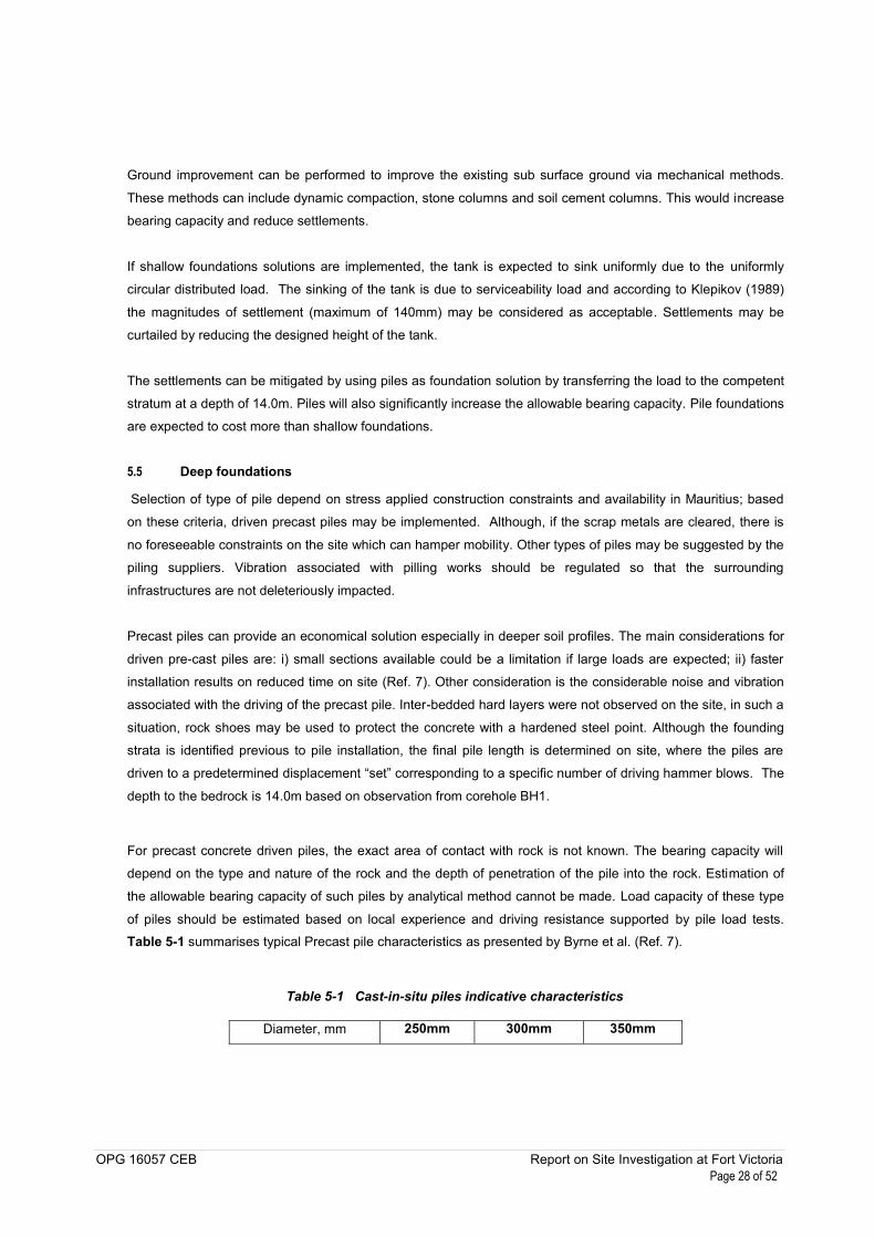
of piles should be estimated based on local experience and driving resistance supported by pile load tests. Table 5-1 summarises typical Precast pile characteristics as presented by Byrne et al. (Ref. 7).
Table 5-1 Cast-in-situ piles indicative characteristics
Diameter, mm 250mm 300mm 350mm
OPG 16057 CEB Report on Site Investigation at Fort Victoria Page 29 of 52
Square Square Square
Typical working load,
kN*
800 - 1000 1200 - 1500 1600 - 2000
Max depth, m Unlimited
Minimum pile spacing
c/c, m
750 900 1050
*Note: The typical working loads are related to the structural characteristics of the piles and not to the soil conditions – the
latter is given below. If the rock is strong at its surface, the carrying capacity of the piles is governed by the strength of the pile
as structural element.
5.5.1 Buried Concrete
An Aggressive Chemical Environment for Concrete (ACEC) site classification has been carried out based on
Water Soluble Sulphate content (2:1 water-soil extract) and pH tests on similar marine deposit samples. The
evaluation is carried out following the UK Building Research Establishment (BRE) Special Digest SD1, Concrete
in Aggressive Ground 2005 (Ref. 8). Typical results for Water Soluble Sulphate content (2:1 water-soil extract)
on the clayey weathered basalts vary between 0.05% and 0.07%; Water-soluble Chloride Content varied
between 0.03% and 0.07%.
Based on these results, a Design Sulphate Class DS-1 and ACEC Class AC-1, for mobile groundwater, can be
used for buried concrete structures. Exposure of concrete to potentially brackish (~10 000 mg/l chloride) or
similarly saline groundwater is, however, beyond the scope of this recommendation.
5.5.2 Conclusions
Based on the analyses presented above, the recommended bearing capacity for the 6,500m3 tank is in the
order of 145kPa with maximum settlements of 140mm for a factor of safety of 2.8. If shallow foundations
solutions are implemented, the tank is expected to sink uniformly. The sinking of the tank is due to serviceability
load and according to Klepikov (1989) the magnitudes of settlement (maximum of 140mm) may be considered
as acceptable
The settlements can be neutralised by using piles as foundation solution by transferring the load to the
competent stratum at a depth of 14.0m
OPG 16057 CEB Report on Site Investigation at Fort Victoria Page 30 of 52
References
1. Ile Maurice Carte Geologique et Hydrogeologique (1996), Republique de Maurice.
2. Proag, V. (1995), The geology and water resources of Mauritius, analysis, Mahatma Gandhi Institute.
3. Directorate of overseas surveys (UK) (1962), Soil Map of Mauritius, Public Works and Survey Department,
Port Louis Mauritius.
4. British Standards (1999), BS 5930, Code of practice for site investigations.
5. British Standards (1990), BS 1377, Methods of tests for soils for Civil Engineering purposes.
6. Transport and Road Research Laboratory (1986), Operation instructions for the TRRL dynamic cone
penetrometer, TRRL Information Note. UK.
7. Tomlinson, Foundation Design and Construction, Seventh Edition, Pearson Education Limited, 2001
8. Stroud, M A (1989), The Standard Penetration Test – its application and interpretation, Penetration Testing
in the UK, Thomas Telford
9. Burland, JB and Burbidge, MC (1985), Settlement of foundations on sand and gravel. Proc Instn Civ Engrs,
part 1.
10. Prakash S., Sharma H. (1990), Pile Foundations in Engineering Practice, John Wiley and Sons Inc.
11. Environment Agency (2009), Technical Note Science Project, Environment Agency UK.
12. Canadian Soil Quality Guidelines for the protection of Environmental and Human Health (2007), Canadian
Soil Quality Guidelines, Table 1, Canadian Council of Ministers of the Environment.
OPG 16057 CEB Report on Site Investigation at Fort Victoria Page 31 of 52
Figures
Figure 2-1 General location of the site
Site
North

OPG 16057 CEB Report on Site Investigation at Fort Victoria Page 32 of 52
Figure 2-2 Site Location
North
Site
OPG 16057 CEB Report on Site Investigation at Fort Victoria Page 33 of 52
Figure 2-3 Aerial Map of site and location of Trial Pits and Coreholes
Site
OPG 16057 CEB Report on Site Investigation at Fort Victoria Page 34 of 52
Figure 2-4 Location of the site on geological map
North
Site
OPG 16057 CEB Report on Site Investigation at Fort Victoria Page 35 of 52
Figure 2-5 Location of the site on Soil Map
Site
OPG 16057 CEB Report on Site Investigation at Fort Victoria Page 36 of 52
Job: OPG 16057 CEB Figure: 4.1Date: March 2016
0
1
2
3
4
5
6
7
8
9
10
11
12
13
14
150 10 20 30 40 50
Dept
h (m
)
SPT N Values
BH 1
Figure 2-6 Standard Penetration Test N Value Variation with Depth – As per Stratum

OPG 16057 CEB Report on Site Investigation at Fort Victoria Page 37 of 52
Rock Quality Designation, RQD %
Date: March 2016 Job: OPG 16057 CEB Figure: 4.1
0
2
4
6
8
10
12
14
16
18
200 10 20 30 40 50 60 70 80 90 100
Dep
th (m
)RQD, % BH 1
BH 1
Figure 2-7 Rock Quality Designation Variation with Depth
OPG 16057 CEB Report on Site Investigation at Fort Victoria Page 38 of 52
0
5
10
15
20
25
30
35
40
45
50
55
60
65
70
0 10 20 30 40 50 60 70 80 90 100 110 120
Plas
ticity
Inde
x (%
)
Liquid Limit (%)
A Line Fill Material C to HWB
Low Plasticity High PlasticityIntermediate Plasticity Very High Plasticity Extremely High Plasticity
CL
ME
CE
CV
CH
CI
MI
ML
MH
MV
A-Line Plasticity Chart Figure : 5.1
Figure 2-8 A Line Plasticity Chart
OPG 16057 CEB Report on Site Investigation at Fort Victoria Page 39 of 52
Appendix A Site Layout


OPG 16057 CEB Report on Site Investigation at Fort Victoria Page 40 of 52
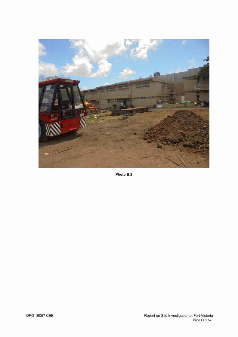
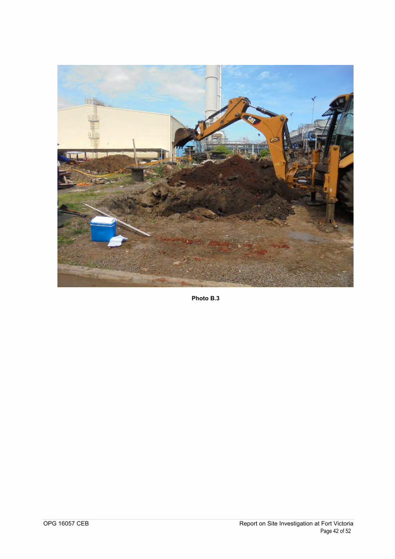
Appendix B Photographs of Site Works
Photo B.1
OPG 16057 CEB Report on Site Investigation at Fort Victoria Page 41 of 52
Photo B.2
OPG 16057 CEB Report on Site Investigation at Fort Victoria Page 42 of 52
Photo B.3

OPG 16057 CEB Report on Site Investigation at Fort Victoria Page 43 of 52
Appendix C Exploratory Hole Logs

OPG 16057 CEB Report on Site Investigation at Fort Victoria Page 44 of 52
Appendix C-1 Corehole Logs
Dark brown very gravelly high plasticitysilty CLAY. FILL MATERIAL?
Soft to firm reddish brown gravelly highplasticity silty CLAY. FILL MATERIAL?
Loose sub-angular fine to medium clayeyGRAVEL of very weak reddish brown Highlyto Completely Weathered Basalt with rarecobbles between 2.25 - 2.35m. Clay isbrown high plasticity FILL MATERIAL?
Loose sub angular fine to medium GRAVEL &COBBLES of strong light grey vesicularSlightly Weathered Basalt. FILL MATERIAL?
Loose sub angular fine to medium denseclayey GRAVEL of very weak dark greyishbrown Highly Weathered Basalt. FILLMATERIAL?
Firm dark brown with mottles highplasticity silty CLAY with cobblesbetween 7.84 - 8.19m. COMPLETELYWEATHERED BASALT.
Firm reddish brown with orange & creammottles high plasticity silty CLAY.COMPLETELY WEATHERED BASALT.
Continued next sheet
1.0
2.0
3.0
4.0
5.0
6.0
7.0
8.0
9.0
Lege
nd
Sca
le (m
)
Ele
vatio
n/D
epth
Sam
ple
/ In
Situ
N V
alue
Rec
over
y (c
m)
Cor
e R
un
TCR
(%)
SCR
(%)
RQ
D (%
)
FI Cas
ing
Dep
th
Dril
ling
Test
Description of Strata
BOREHOLE No. :
SITE :
Drilling Rig :
Casing Diameter :
Borehole Diameter :
Core Diameter :
National Grid Coordinates
N :
E :
Ground Level :
Start Date :
End Date :
Final Depth :
Water Depth :
Logged by :
Drillers :
Checked by :
Sheet :Project :Contract No :
Legend : Undisturbed Tube Sample (SPT) Solid Cone Dry Coring
Water Drilling(SPT) Split SpoonDisturbed Sample
Refusal at Jacking of U Sampler
(SPT) Refusal
Non Intact
U :
D :
RU :
R :
C :
S :
NI :
DC :
WD :
M : Mazier Sample
ABYSS 75
OPG 16057 CEB
52mm
88mm
76mm
7770400.00
549897.000
Geotechnical Investigation at Fort Victoria
3.000m amsl
Bain des Dames, les Saline
03/02/2016
02/02/2016
20.00m
3.5m on 02/02/2016
BH 1
1 of 2
MP
ZJ
0.60
2.25
3.50
4.00
6.00
8.10
10.00
SPTLS
U2(R)
SPTLS
SPTLS
SPTLS
(0)
(10)
(11)
>50
(16)
33
40
0
28
34
0.50
1.00
1.50
2.00
2.29
2.78
3.50
4.00
4.42
4.765.00
5.50
6.00
7.50
7.84
8.19
9.50
10.00
100
100
100
0
100
100
100
100
100
100100
100
0
100
0
100
100
0
0
0
0
0
0
0
0
0
0
00
0
0
0
0
0
0
0
0
0
0
0
0
0
0
0
0
00
0
0
0
0
0
0
0
NW6.00
DC
- 76
mm
DC
- 52
mm

Firm reddish brown with cream & blackmottles high plasticity silty CLAY.COMPLETELY TO HIGHLY WEATHEREDBASALT.
Weak to moderately weak creamish greywith black mottles at vesicles closeljointed MODERATELY WEATHEREDBASALT. Joints are smooth.
Strong to moderately strong light greyvesicular closely-medium jointed SLIGHTLYWEATHERED BASALT. Joints are planarsmooth sub horizontal in-filled withcream clay.
Moderately weak to moderately strong greywith yellow & black mottles at vesicleswith frequent amygdales very closelyjointed MODERATELY WEATHEREDBASALT. Joints are undulating rough subhorizontal in-filled with reddish brownclay.
End of Borehole at 20.00 m
11.0
12.0
13.0
14.0
15.0
16.0
17.0
18.0
19.0
Lege
nd
Sca
le (m
)
Ele
vatio
n/D
epth
Sam
ple
/ In
Situ
N V
alue
Rec
over
y (c
m)
Cor
e R
un
TCR
(%)
SCR
(%)
RQ
D (%
)
FI Cas
ing
Dep
th
Dril
ling
Test
Description of Strata
BOREHOLE No. :
SITE :
Drilling Rig :
Casing Diameter :
Borehole Diameter :
Core Diameter :
National Grid Coordinates
N :
E :
Ground Level :
Start Date :
End Date :
Final Depth :
Water Depth :
Logged by :
Drillers :
Checked by :
Sheet :Project :Contract No :
Legend : Undisturbed Tube Sample (SPT) Solid Cone Dry Coring
Water Drilling(SPT) Split SpoonDisturbed Sample
Refusal at Jacking of U Sampler
(SPT) Refusal
Non Intact
U :
D :
RU :
R :
C :
S :
NI :
DC :
WD :
M : Mazier Sample
ABYSS 75
OPG 16057 CEB
52mm
88mm
76mm
7770400.00
549897.000
Geotechnical Investigation at Fort Victoria
3.000m amsl
Bain des Dames, les Saline
03/02/2016
02/02/2016
20.00m
3.5m on 02/02/2016
BH 1
2 of 2
MP
ZJ
13.55
14.33
17.64
20.00
SPTLS (22) 28
11.60
13.00
13.50
14.00
14.33
16.00
17.64
19.00
20.00
100
100
0
100
100
100
100
100
100
0
0
0
12
23
72
53
29
25
0
0
0
0
0
61
34
16
0
17
9
10
WD
- 52
mm

OPG 16057 CEB Report on Site Investigation at Fort Victoria Page 45 of 52
Appendix C-2 Photographs of Cores
GEOTECHNICAL INVESTIGATION AT PORT LOUIS FORT
VICTORIA
BH1
Page 1 of 4
CLIENT: CENTRAL ELECTRICITY BOARD
CONTRACT No.: OPG 16057 CEB
COREHOLE BH1
Depth: 0.00 –6.00 metres
CLIENT: CENTRAL ELECTRICITY BOARD PROJECT: GEOTECHNICAL INVESTIGATION AT FORT VICTORIA SITE: PORT LOUIS FORT VICTORIA C/HOLE: BH01 DEPTH: 0.00 – 2.00m DATE: 02/02/2016
CORE RUN: 0.00 – 0.50m 0.50 – 1.00m
1.00 – 1.50m 1.50 – 2.00m
CLIENT: CENTRAL ELECTRICITY BOARD PROJECT: GEOTECHNICAL INVESTIGATION AT FORT VICTORIA SITE: PORT LOUIS FORT VICTORIA C/HOLE: BH01 DEPTH: 2.00 – 4.00m DATE: 02/02/2016
CORE RUN: 2.00 – 2.29m 2.29 – 2.78m
2.78 – 3.50m 3.50 – 4.00m
CLIENT: CENTRAL ELECTRICITY BOARD PROJECT: GEOTECHNICAL INVESTIGATION AT FORT VICTORIA SITE: PORT LOUIS FORT VICTORIA C/HOLE: BH01 DEPTH: 4.00 – 6.00m DATE: 02/02/2016
CORE RUN: 4.00 – 4.42m 4.42 – 4.76m
4.76 – 5.00m 5.00 – 5.50m 5.50 – 6.00m
SPT 3 – Depth: 5.50 – 6.00m Penetration: 000 – 150mm = 3
150 – 225mm = 3 225 – 300mm = 4 300 – 375mm = 2 375 – 450mm = 2 N Value = 11 Recovery = 28cm
SPT 2 – Depth: 3.50m
Recovery = Refusal
SPT 1 – Depth: 1.50 – 2.00m Penetration: 000 – 150mm = 2
150 – 225mm = 3 225 – 300mm = 3 300 – 375mm = 2 375 – 450mm = 2 N Value = 10 Recovery = 40cm

GEOTECHNICAL INVESTIGATION AT PORT LOUIS FORT
VICTORIA
BH1
Page 2 of 4
CLIENT: CENTRAL ELECTRICITY BOARD
CONTRACT No.: OPG 16057 CEB
COREHOLE BH1
Depth: 6.00 –12.00 metres
CLIENT: CENTRAL ELECTRICITY BOARD PROJECT: GEOTECHNICAL INVESTIGATION AT FORT VICTORIA SITE: PORT LOUIS FORT VICTORIA C/HOLE: BH01 DEPTH: 6.00 – 8.00m DATE: 02/02/2016
CORE RUN: 6.00 – 7.50m 7.50 – 7.84m 7.84 – 8.19m
SPT 4 – Depth: 7.50 – 7.84m Penetration: 000 – 150mm = 11
150 – 225mm = 8 225 – 300mm = 12 300 – 375mm = 51 N Value = 71 Recovery = 34cm
CLIENT: CENTRAL ELECTRICITY BOARD PROJECT: GEOTECHNICAL INVESTIGATION AT FORT VICTORIA SITE: PORT LOUIS FORT VICTORIA C/HOLE: BH01 DEPTH: 8.00 – 10.00m DATE: 02/02/2016
CORE RUN: 8.19 – 9.50m 9.50 – 10.00m
CLIENT: CENTRAL ELECTRICITY BOARD PROJECT: GEOTECHNICAL INVESTIGATION AT FORT VICTORIA SITE: PORT LOUIS FORT VICTORIA C/HOLE: BH01 DEPTH: 10.00 – 12.00m DATE: 03/02/2016
CORE RUN: 10.00 – 11.60m 11.60 – 13.00m
SPT 5 – Depth: 9.50 – 10.00m Penetration: 000 – 150mm = 5
150 – 225mm = 6 225 – 300mm = 4 300 – 375mm = 3 375 – 450mm = 3 N Value = 16 Recovery = 28cm
GEOTECHNICAL INVESTIGATION AT PORT LOUIS FORT
VICTORIA
BH1
Page 3 of 4
CLIENT: CENTRAL ELECTRICITY BOARD
CONTRACT No.: OPG 16057 CEB
COREHOLE BH1
Depth: 12.00 –14.00 metres
CLIENT: CENTRAL ELECTRICITY BOARD PROJECT: GEOTECHNICAL INVESTIGATION AT FORT VICTORIA SITE: PORT LOUIS FORT VICTORIA C/HOLE: BH01 DEPTH: 12.00 – 14.00m DATE: 03/02/2016
CORE RUN: 13.00 – 13.50m 13.50 – 14.00m
SPT 6 – Depth: 13.00 – 13.50m Penetration: 000 – 150mm = 5
150 – 225mm = 6 225 – 300mm = 6 300 – 375mm = 6 375 – 450mm = 4 N Value = 22 Recovery = 33cm
CLIENT: CENTRAL ELECTRICITY BOARD PROJECT: GEOTECHNICAL INVESTIGATION AT FORT VICTORIA SITE: PORT LOUIS FORT VICTORIA C/HOLE: BH01 DEPTH: 14.00 – 16.00m DATE: 03/02/2016
CORE RUN: 14.00 – 14.33m 14.33 – 16.00m
CLIENT: CENTRAL ELECTRICITY BOARD PROJECT: GEOTECHNICAL INVESTIGATION AT FORT VICTORIA SITE: PORT LOUIS FORT VICTORIA C/HOLE: BH01 DEPTH: 16.00 – 18.00m DATE: 03/02/2016
CORE RUN: 16.00 – 17.64m 17.64 – 19.00m

GEOTECHNICAL INVESTIGATION AT PORT LOUIS FORT
VICTORIA
BH1
Page 4 of 4
CLIENT: CENTRAL ELECTRICITY BOARD
CONTRACT No.: OPG 16057 CEB
COREHOLE BH1
Depth: 18.00 –20.00 metres
End of Corehole at 20.00 metres
CLIENT: CENTRAL ELECTRICITY BOARD PROJECT: GEOTECHNICAL INVESTIGATION AT FORT VICTORIA SITE: PORT LOUIS FORT VICTORIA C/HOLE: BH01 DEPTH: 18.00 – 20.00m DATE: 03/02/2016
CORE RUN: 19.00 – 20.00m
OPG 16057 CEB Report on Site Investigation at Fort Victoria Page 46 of 52
Appendix C-3 Trial Pit Logs

TRIALPIT No. :
SITE :
Method : National Grid Coordinates
N :
E :
Ground Level :
Start Date :
End Date :
Final Depth :
Water Depth :
Sheet :Project :Contract No :
Logged by :Checked by :
NotationP : Percolation TestDT : In Situ Density TestPP : Pocket PenetrometerSB : Small BulkLB : Large Bulk
Remarks :
Description of strataInsitu density/Percolation/
Pocket Pen. kPa
Depthof
WaterStrikes
SampleType
Lege
nd
Sca
le (m
)
Ele
vatio
n/D
epth
Mechanically Excavated
TP 0.4m above G.L
OPG 16057 CEB
7770411.00
549914.000
Geotechnical Investigation at Fort Victoria
3.000m amsl
Bain des Dames, les Saline
04/02/2016
04/02/2016
2.55m
Not Encountered
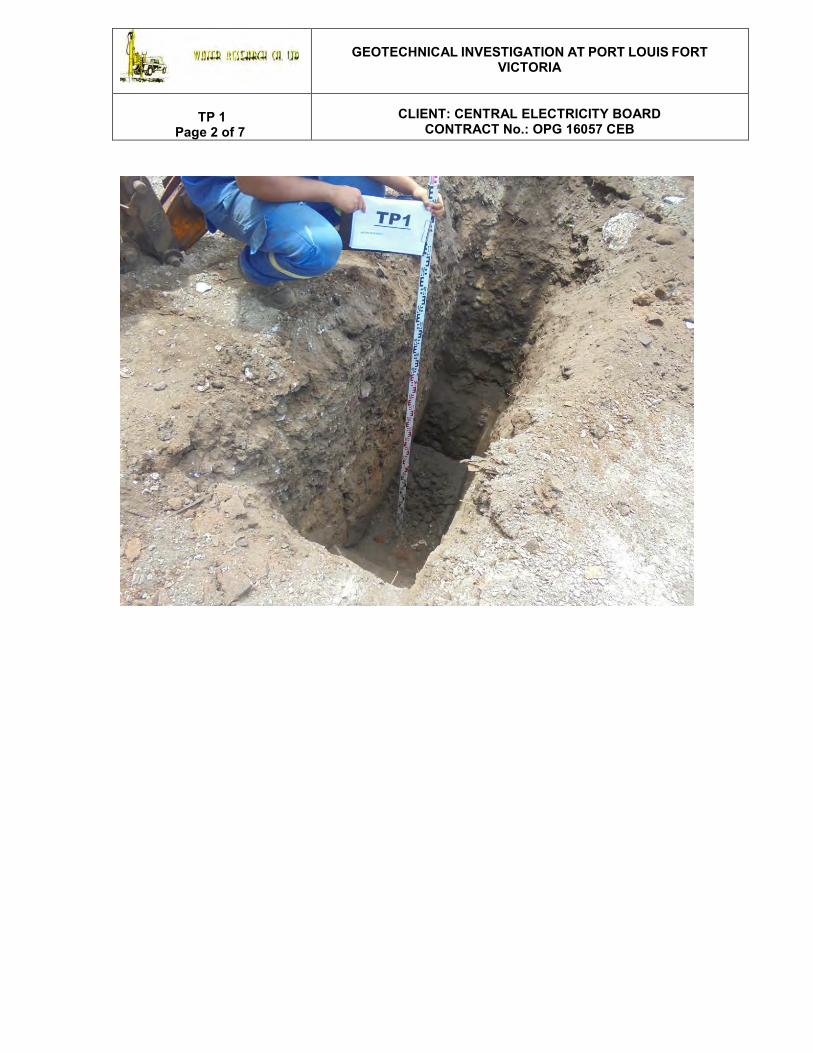
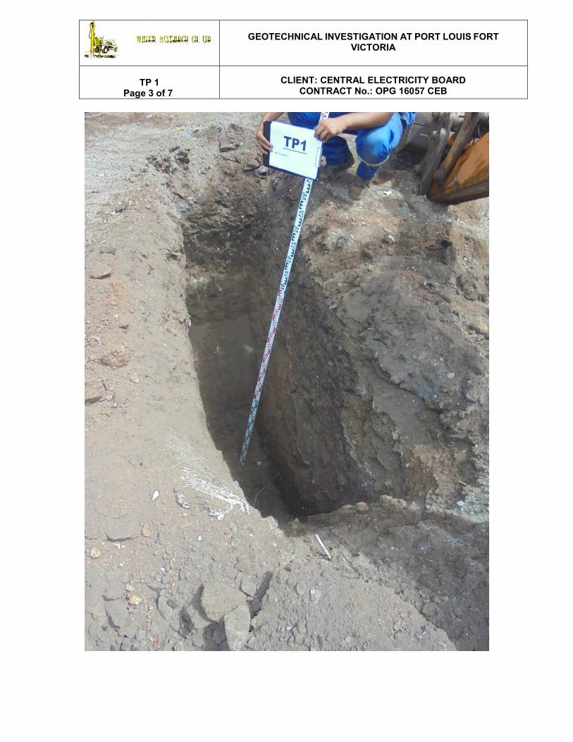
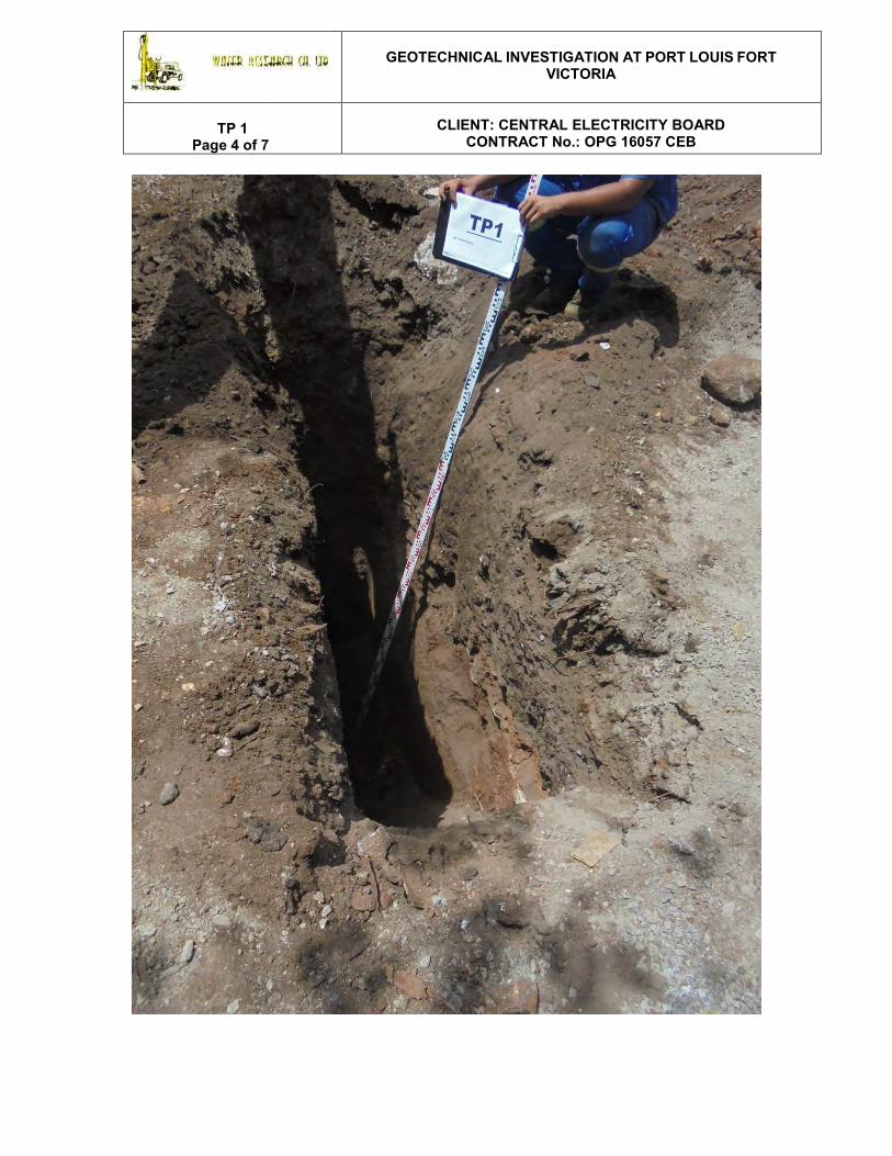
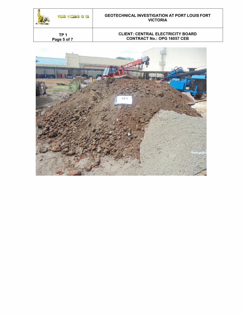
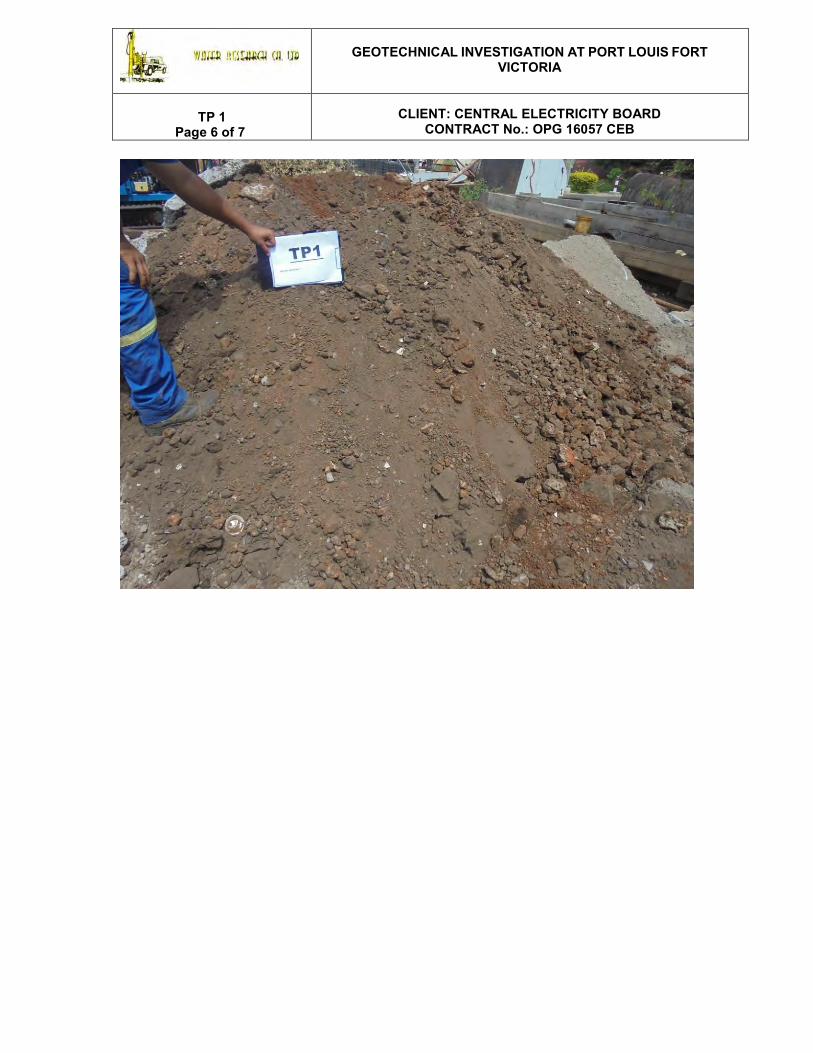
TP 1
1 of 1
ZJ
1.15
2.55
SBLB
SBLB
Firm to stiff dark brown medium plasticity CLAY with debrissuch as plastic and glass bottles, concrete and roots. FILLMATERIAL.
Firm to stiff reddish brown with orange and cream mottlesgravelly high plasticity CLAY. Gravels are sub rounded tosub angular medium to coarse moderately strong light grey ofModerately Weathered Basalt. COMPLETELY TO HIGHLYWEATHERED BASALT
End of Trialpit at 2.55 m
1.0
2.0
TRIALPIT No. :
SITE :
Method : National Grid Coordinates
N :
E :
Ground Level :
Start Date :
End Date :
Final Depth :
Water Depth :
Sheet :Project :Contract No :
Logged by :Checked by :
NotationP : Percolation TestDT : In Situ Density TestPP : Pocket PenetrometerSB : Small BulkLB : Large Bulk
Remarks :
Description of strataInsitu density/Percolation/
Pocket Pen. kPa
Depthof
WaterStrikes
SampleType
Lege
nd
Sca
le (m
)
Ele
vatio
n/D
epth
Mechnicaly Excavated
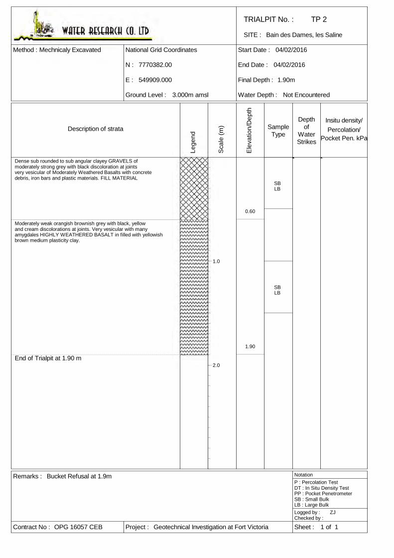
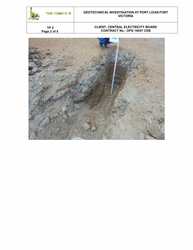
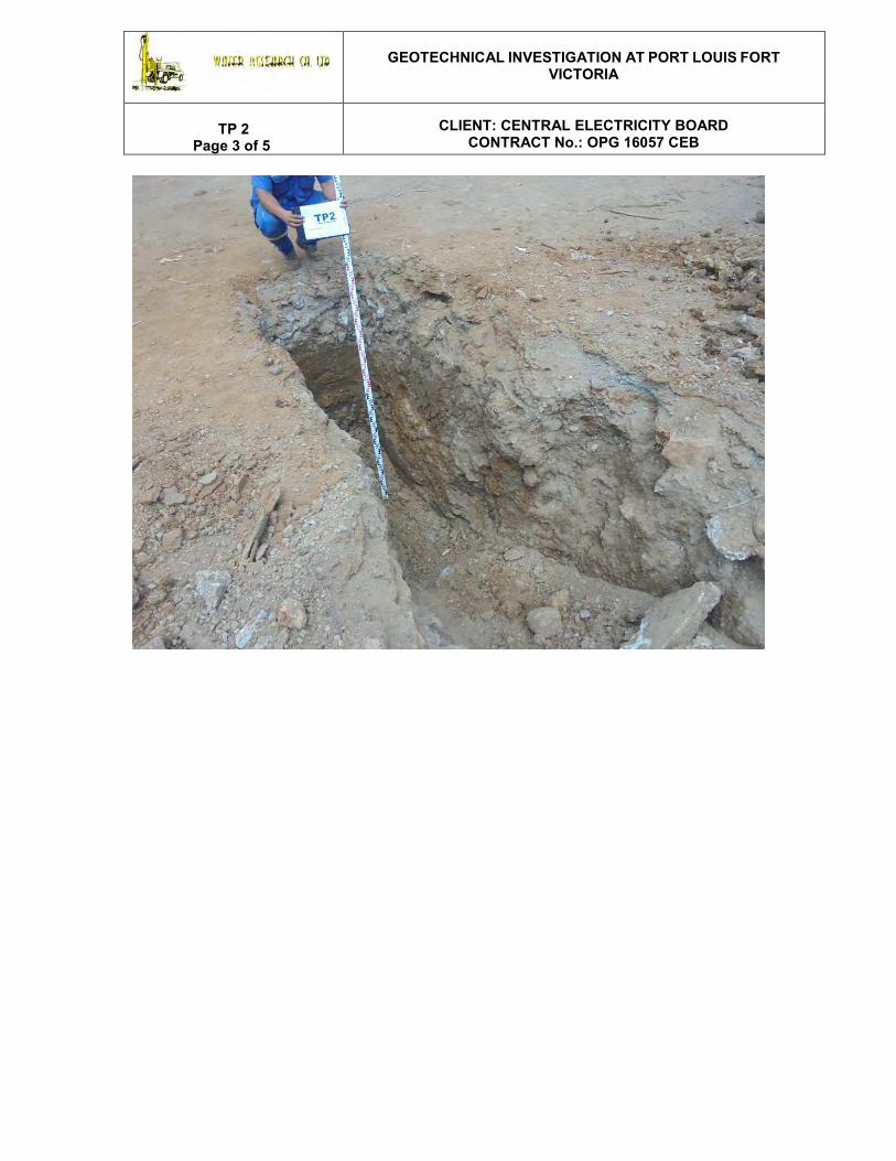
Bucket Refusal at 1.9m
OPG 16057 CEB
7770382.00
549909.000
Geotechnical Investigation at Fort Victoria
3.000m amsl
Bain des Dames, les Saline
04/02/2016
04/02/2016
1.90m
Not Encountered
TP 2
1 of 1
ZJ
0.60
1.90
SBLB
SBLB
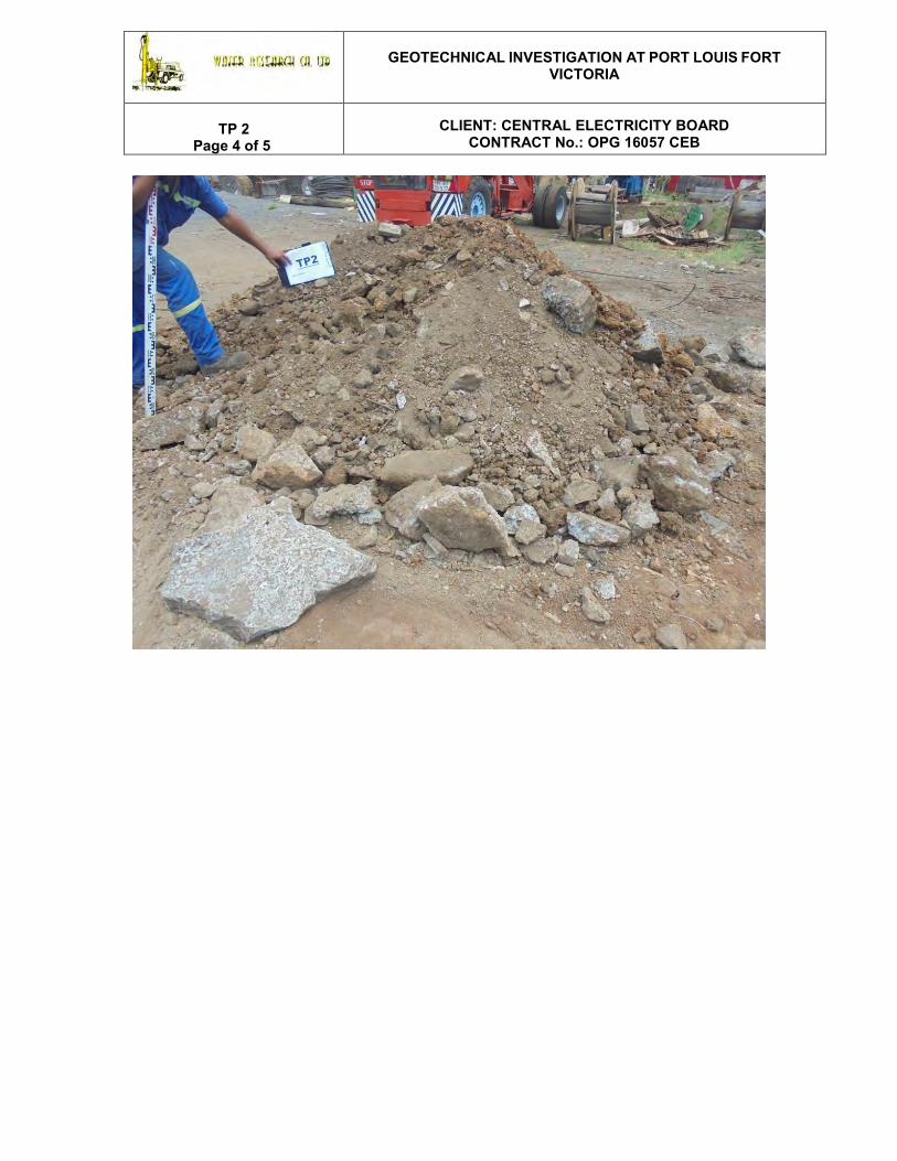
Dense sub rounded to sub angular clayey GRAVELS ofmoderately strong grey with black discoloration at jointsvery vesicular of Moderately Weathered Basalts with concretedebris, iron bars and plastic materials. FILL MATERIAL
Moderately weak orangish brownish grey with black, yellowand cream discolorations at joints. Very vesicular with manyamygdales HIGHLY WEATHERED BASALT in filled with yellowishbrown medium plasticity clay.
End of Trialpit at 1.90 m
1.0
2.0

TRIALPIT No. :
SITE :
Method : National Grid Coordinates
N :
E :
Ground Level :
Start Date :
End Date :
Final Depth :
Water Depth :
Sheet :Project :Contract No :
Logged by :Checked by :
NotationP : Percolation TestDT : In Situ Density TestPP : Pocket PenetrometerSB : Small BulkLB : Large Bulk
Remarks :
Description of strataInsitu density/Percolation/
Pocket Pen. kPa
Depthof
WaterStrikes
SampleType
Lege
nd
Sca
le (m
)
Ele
vatio
n/D
epth
Mechanically Excavated
OPG 16057 CEB
7770409.00
549907.000
Geotechnical Investigation at Fort Victoria
3.000m amsl
Bain des Dames, les Saline
23/02/2016
23/02/2016
1.50m
Not Encountered
TP 3
1 of 1
OB
0.30
0.90
1.50
SB
SB
Soft light grey strong brown very gravelly sandy SILTY withfrequent concrete blocks. TOPSOIL.
Soft black very gravelly medium plasticity silty CLAY withvarious fragments of glasses, pipes. FILL MATERIAL.
Firm moist reddish brown high plasticity gravelly siltyCLAY. COMPLETELY WEATHERED BASALT.
End of Trialpit at 1.50 m
1.0
2.0
TRIALPIT No. :
SITE :
Method : National Grid Coordinates
N :
E :
Ground Level :
Start Date :
End Date :
Final Depth :
Water Depth :
Sheet :Project :Contract No :
Logged by :Checked by :
NotationP : Percolation TestDT : In Situ Density TestPP : Pocket PenetrometerSB : Small BulkLB : Large Bulk
Remarks :
Description of strataInsitu density/Percolation/
Pocket Pen. kPa
Depthof
WaterStrikes
SampleType
Lege
nd
Sca
le (m
)
Ele
vatio
n/D
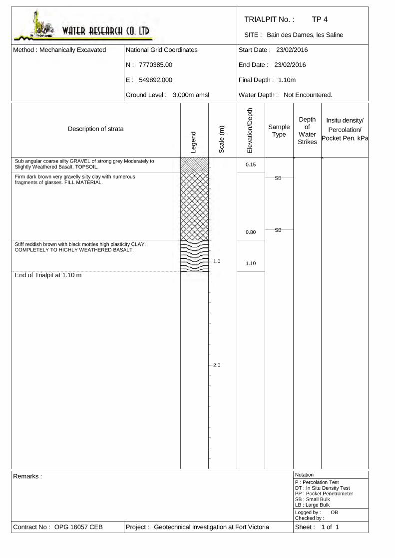
epth
Mechanically Excavated
OPG 16057 CEB
7770385.00
549892.000
Geotechnical Investigation at Fort Victoria
3.000m amsl
Bain des Dames, les Saline
23/02/2016
23/02/2016
1.10m
Not Encountered.
TP 4
1 of 1
OB
0.15
0.80
1.10
SB
SB
Sub angular coarse silty GRAVEL of strong grey Moderately toSlightly Weathered Basalt. TOPSOIL.
Firm dark brown very gravelly silty clay with numerousfragments of glasses. FILL MATERIAL.
Stiff reddish brown with black mottles high plasticity CLAY.COMPLETELY TO HIGHLY WEATHERED BASALT.
End of Trialpit at 1.10 m
1.0
2.0
OPG 16057 CEB Report on Site Investigation at Fort Victoria Page 47 of 52
Appendix C-4 Photographs of Trial Pits
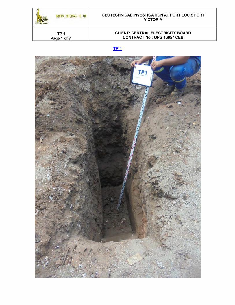
GEOTECHNICAL INVESTIGATION AT PORT LOUIS FORT
VICTORIA
TP 1 Page 1 of 7
CLIENT: CENTRAL ELECTRICITY BOARD
CONTRACT No.: OPG 16057 CEB
TP 1
GEOTECHNICAL INVESTIGATION AT PORT LOUIS FORT
VICTORIA
TP 1 Page 2 of 7
CLIENT: CENTRAL ELECTRICITY BOARD
CONTRACT No.: OPG 16057 CEB
GEOTECHNICAL INVESTIGATION AT PORT LOUIS FORT
VICTORIA
TP 1 Page 3 of 7
CLIENT: CENTRAL ELECTRICITY BOARD
CONTRACT No.: OPG 16057 CEB
GEOTECHNICAL INVESTIGATION AT PORT LOUIS FORT
VICTORIA
TP 1 Page 4 of 7
CLIENT: CENTRAL ELECTRICITY BOARD
CONTRACT No.: OPG 16057 CEB
GEOTECHNICAL INVESTIGATION AT PORT LOUIS FORT
VICTORIA
TP 1 Page 5 of 7
CLIENT: CENTRAL ELECTRICITY BOARD
CONTRACT No.: OPG 16057 CEB
GEOTECHNICAL INVESTIGATION AT PORT LOUIS FORT
VICTORIA
TP 1 Page 6 of 7
CLIENT: CENTRAL ELECTRICITY BOARD
CONTRACT No.: OPG 16057 CEB

GEOTECHNICAL INVESTIGATION AT PORT LOUIS FORT
VICTORIA
TP 1 Page 7 of 7
CLIENT: CENTRAL ELECTRICITY BOARD
CONTRACT No.: OPG 16057 CEB
Final Depth at 2.55metres

GEOTECHNICAL INVESTIGATION AT PORT LOUIS FORT
VICTORIA
TP 2 Page 1 of 5
CLIENT: CENTRAL ELECTRICITY BOARD
CONTRACT No.: OPG 16057 CEB
TP 2
GEOTECHNICAL INVESTIGATION AT PORT LOUIS FORT
VICTORIA
TP 2 Page 2 of 5
CLIENT: CENTRAL ELECTRICITY BOARD
CONTRACT No.: OPG 16057 CEB
GEOTECHNICAL INVESTIGATION AT PORT LOUIS FORT
VICTORIA
TP 2 Page 3 of 5
CLIENT: CENTRAL ELECTRICITY BOARD
CONTRACT No.: OPG 16057 CEB
GEOTECHNICAL INVESTIGATION AT PORT LOUIS FORT
VICTORIA
TP 2 Page 4 of 5
CLIENT: CENTRAL ELECTRICITY BOARD
CONTRACT No.: OPG 16057 CEB

GEOTECHNICAL INVESTIGATION AT PORT LOUIS FORT
VICTORIA
TP 2 Page 5 of 5
CLIENT: CENTRAL ELECTRICITY BOARD
CONTRACT No.: OPG 16057 CEB
Final Depth at 1.90 metres

GEOTECHNICAL INVESTIGATION AT PORT LOUIS FORT
VICTORIA
TP 3 Page 1 of 2
CLIENT: CENTRAL ELECTRICITY BOARD
CONTRACT No.: OPG 16057 CEB
TP 3
GEOTECHNICAL INVESTIGATION AT PORT LOUIS FORT
VICTORIA
TP 3 Page 2 of 2
CLIENT: CENTRAL ELECTRICITY BOARD
CONTRACT No.: OPG 16057 CEB
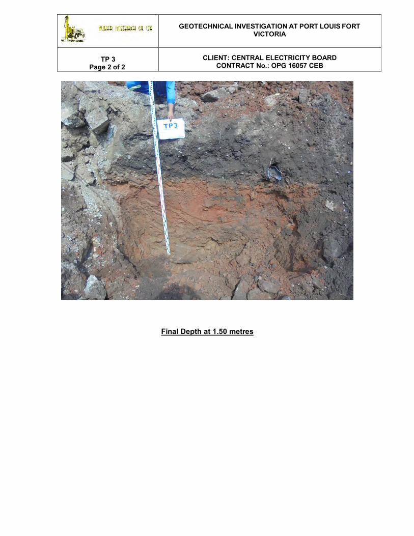
Final Depth at 1.50 metres

GEOTECHNICAL INVESTIGATION AT PORT LOUIS FORT
VICTORIA
TP 4 Page 1 of 4
CLIENT: CENTRAL ELECTRICITY BOARD
CONTRACT No.: OPG 16057 CEB
TP 4

GEOTECHNICAL INVESTIGATION AT PORT LOUIS FORT
VICTORIA
TP 4 Page 2 of 4
CLIENT: CENTRAL ELECTRICITY BOARD
CONTRACT No.: OPG 16057 CEB

GEOTECHNICAL INVESTIGATION AT PORT LOUIS FORT
VICTORIA
TP 4 Page 3 of 4
CLIENT: CENTRAL ELECTRICITY BOARD
CONTRACT No.: OPG 16057 CEB

GEOTECHNICAL INVESTIGATION AT PORT LOUIS FORT
VICTORIA
TP 4 Page 4 of 4
CLIENT: CENTRAL ELECTRICITY BOARD
CONTRACT No.: OPG 16057 CEB
Final Depth at 1.10 metres