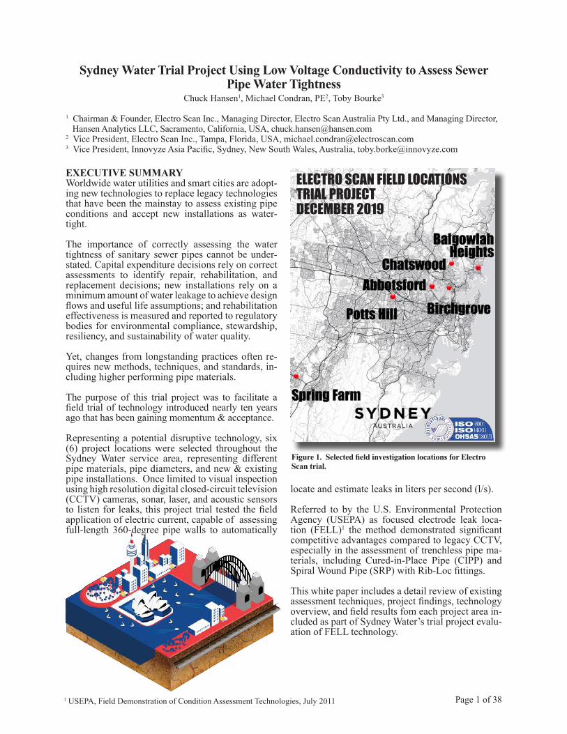
executive summary electro scan field locations trial ... · cently lined cast iron pipes. one pipe...
TRANSCRIPT
Sydney Water Trial Project Using Low Voltage Conductivity to Assess SewerPipe Water Tightness
Chuck Hansen1, Michael Condran, PE2, Toby Bourke3
1 Chairman & Founder, Electro Scan Inc., Managing Director, Electro Scan Australia Pty Ltd., and Managing Director, Hansen Analytics LLC, Sacramento, California, USA, [email protected] Vice President, Electro Scan Inc., Tampa, Florida, USA, [email protected] Vice President, Innovyze Asia Pacific, Sydney, New South Wales, Australia, [email protected]
Page 1 of 38
EXECUTIVE SUMMARYWorldwide water utilities and smart cities are adopt-ing new technologies to replace legacy technologies that have been the mainstay to assess existing pipe conditions and accept new installations as water-tight.
The importance of correctly assessing the water tightness of sanitary sewer pipes cannot be under-stated. Capital expenditure decisions rely on correct assessments to identify repair, rehabilitation, and replacement decisions; new installations rely on a minimum amount of water leakage to achieve design flows and useful life assumptions; and rehabilitation effectiveness is measured and reported to regulatory bodies for environmental compliance, stewardship, resiliency, and sustainability of water quality.
Yet, changes from longstanding practices often re-quires new methods, techniques, and standards, in-cluding higher performing pipe materials.
The purpose of this trial project was to facilitate a field trial of technology introduced nearly ten years ago that has been gaining momentum & acceptance.
Representing a potential disruptive technology, six (6) project locations were selected throughout the Sydney Water service area, representing different pipe materials, pipe diameters, and new & existing pipe installations. Once limited to visual inspection using high resolution digital closed-circuit television (CCTV) cameras, sonar, laser, and acoustic sensors to listen for leaks, this project trial tested the field application of electric current, capable of assessing full-length 360-degree pipe walls to automatically
locate and estimate leaks in liters per second (l/s).
Referred to by the U.S. Environmental Protection Agency (USEPA) as focused electrode leak loca-tion (FELL)1 the method demonstrated significant competitive advantages compared to legacy CCTV, especially in the assessment of trenchless pipe ma-terials, including Cured-in-Place Pipe (CIPP) and Spiral Wound Pipe (SRP) with Rib-Loc fittings.
This white paper includes a detail review of existing assessment techniques, project findings, technology overview, and field results fom each project area in-cluded as part of Sydney Water’s trial project evalu-ation of FELL technology.
Figure 1. Selected field investigation locations for Electro Scan trial.
ELECTRO SCAN FIELD LOCATIONSTRIAL PROJECTDECEMBER 2019
1 USEPA, Field Demonstration of Condition Assessment Technologies, July 2011
SYDNEY WATER BUSINESS CASEA Business Case was developed in October 2019 by Sydney Water’s Urban Design and Engineering team to justify the evaluation Electro Scan’s patent-ed protected low voltage conductivity technology.
The Sydney Water Business Case established that the purpose of its evaluation was to test and document the practical application, field operation, ease of report-ing, and data production, utilising ASTM F2550-13 (2018), compared to traditional Closed-Circuit Tele-vision (CCTV) inspection utilising WSA 05—2008 2.2 Conduit Inspection Reporting Code of Australia standards.
Key questions, included the following:1. Does FELL technology deliver repeatable leak
location and severity measurements not provided by traditional CCTV visual inspection?
2. Can FELL technology be used to more accu-rately locate infiltration and exfiltration?
3. What are FELL advantages & disadvantages?
4. How should new (possible) quality standards be introduced during start-up & operation of Sydney Water’s Regional Delivery Consor-tium (RDC)? NOTE: This issue is outside the scope of this white paper.
Key Findings from Electro Scan Trial Project The Electro Scan pilot project demonstrated signifi-cant drawbacks to Sydney Water’s present standards for testing existing sewer mains for water tightness, and more importantly, acceptance of repairs, reha-bilitation, and replacements.
Six (6) locations were selected to provide a targeted mix of new and existing pipe materials.
Page 2 of 38
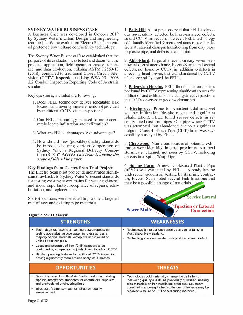
Figure 2. SWOT Analysis
1. Potts Hill. A test pipe observed that FELL technol-ogy successfully detected both pre-arranged defects, as did CCTV inspection; however, FELL technology additionally identified & measured numerous other de-fects at material changes transitioning from clay pipe-to-plastic pipe, and defects at each joint.
2. Abbotsford. Target of a recent sanitary sewer over-flow into a customer’s home, Electro Scan found several defects, not found by CCTV, in addition to defects in a recently lined sewer, that was abandoned by CCTV after successfully tested by FELL.
3. Balgowlah Heights. FELL found numerous defects not found by CCTV representing significant sources for infiltration and exfiltration, including defective junctions that CCTV observed in good workmanship.
4. Birchgrove. Prone to persistent tidal and wet weather infiltration (despite recent and significant rehabilitation), FELL found severe defects in re-cently lined cast iron pipes. One pipe where CCTV was attempted, but abandoned due to a significant bulge in Cured-In-Place Pipe (CIPP) liner, was suc-cessfully surveyed by FELL.
5. Chatswood. Numerous sources of potential exfil-tration were identified in close proximity to a local stormwater channel, not seen by CCTV, including defects in a Spiral Wrap Pipe.
6. Spring Farm. A new Unplastised Plastic Pipe (uPVC) was evaluated by FELL. Already having undergone vacuum air testing by its prime contrac-tor, Electro Scan noted several leak locations that may be a possible change of materials.
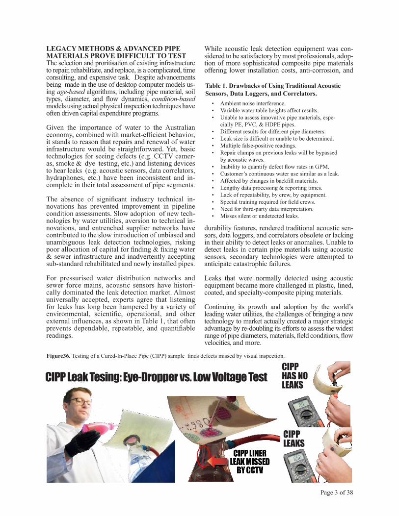
Sewer MainJunction or Lateral
Connection
Service Lateral
LEGACY METHODS & ADVANCED PIPEMATERIALS PROVE DIFFICULT TO TESTThe selection and proritisation of existing infrastructure to repair, rehabilitate, and replace, is a complicated, time consulting, and expensive task. Despite advancements being made in the use of desktop computer models us-ing age-based algorithms, including pipe material, soil types, diameter, and flow dynamics, condition-based models using actual physical inspection techniques have often driven capital expenditure programs.
Given the importance of water to the Australian economy, combined with market-efficient behavior, it stands to reason that repairs and renewal of water infrastructure would be straightforward. Yet, basic technologies for seeing defects (e.g. CCTV camer-as, smoke & dye testing, etc.) and listening devices to hear leaks (e.g. acoustic sensors, data correlators, hydraphones, etc.) have been inconsistent and in-complete in their total assessment of pipe segments.
The absence of significant industry technical in-novations has prevented improvement in pipeline condition assessments. Slow adoption of new tech-nologies by water utilities, aversion to technical in-novations, and entrenched supplier networks have contributed to the slow introduction of unbiased and unambiguous leak detection technologies, risking poor allocation of capital for finding & fixing water & sewer infrastructure and inadvertently accepting sub-standard rehabilitated and newly installed pipes.
For pressurised water distribution networks and sewer force mains, acoustic sensors have histori-cally dominated the leak detection market. Almost universally accepted, experts agree that listening for leaks has long been hampered by a variety of environmental, scientific, operational, and other external influences, as shown in Table 1, that often prevents dependable, repeatable, and quantifiable readings.
While acoustic leak detection equipment was con-sidered to be satisfactory by most professionals, adop-tion of more sophisticated composite pipe materials offering lower installation costs, anti-corrosion, and
durability features, rendered traditional acoustic sen-sors, data loggers, and correlators obsolete or lacking in their ability to detect leaks or anomalies. Unable to detect leaks in certain pipe materials using acoustic sensors, secondary technologies were attempted to anticipate catastrophic failures.
Leaks that were normally detected using acoustic equipment became more challenged in plastic, lined, coated, and specialty-composite piping materials.
Continuing its growth and adoption by the world’s leading water utilities, the challenges of bringing a new technology to market actually created a major strategic advantage by re-doubling its efforts to assess the widest range of pipe diameters, materials, field conditions, flow velocities, and more.
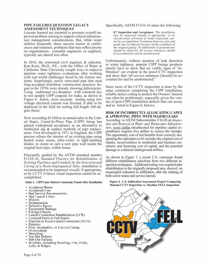
Figure36. Testing of a Cured-In-Place Pipe (CIPP) sample finds defects missed by visual inspection.
CIPPHAS NOLEAKS
CIPPLEAKS
CIPP Leak Tesing: Eye-Dropper vs. Low Voltage Test
Table 1. Drawbacks of Using Traditional Acoustic Sensors, Data Loggers, and Correlators.
• Ambient noise interference.• Variable water table heights affect results.• Unable to assess innovative pipe materials, espe-
cially PE, PVC, & HDPE pipes.• Different results for different pipe diameters.• Leak size is difficult or unable to be determined.• Multiple false-positive readings.• Repair clamps on previous leaks will be bypassed
by acoustic waves.• Inability to quantify defect flow rates in GPM.• Customer’s continuous water use similar as a leak.• Affected by changes in backfill materials.• Lengthy data processing & reporting times.• Lack of repeatability, by crew, by equipment.• Special training required for field crews.• Need for third-party data interpretation.• Misses silent or undetected leaks.
Page 3 of 38
PIPE FAILURES QUESTION LEGACYASSESSMENT TECHNIQUESLessons learned are essential to promote overall im-proved problem solving to support critical infrastruc-ture management considerations. But, while water utilities frequently share success stories at confer-ences and seminars, problems that may reflect poorly on organizations, consultin engineeer, or suppliers, typically are shared less often.
In 2010, the renowned civil engineer & educator, Ken Kerri, Ph.D., P.E., with the Office of Water at California State University sought ways to improve pipeline water tightness evaluations after working with real-world challenges faced by his former stu-dents. Surprisingly, newly renovated pipe that used long-accepted trenchless construction practices be-gun in the 1970s were already showing deficiencies. Using traditional eye-droppers with coloured dye to test sample CIPP coupons for leaks, as shown in Figure 6 below, more accurate testing using low voltage electrical current was favored, if able to be deployed in the field for testing full-length 360-de-gree liners.
Now exceeding $5 billion in annual sales in the Unit-ed States, Cured-In-Place Pipe (CIPP) lining has gained widespread acceptance as an alternative to traditional dig & replace methods of pipe replace-ment. First developed in 1971 in England, the CIPP process relines the interior of an existing pipe using heated water, steam, ultra-violet, or light-emitting diodes, to create or cure a new pipe wall inside the original host pipe, within hours.
Principally guided by the ASTM standard number F1216-16, Standard Practice for Rehabilitation of Existing Pipelines and Conduits by the Inversion and Curing of a Resin-Impregnated Tube, installation is recommended to be inspected visually if appropriate, or by CCTV if direct visual inspection cannot be ac-complished.
Specifically, ASTM F1216-16 states the following:
8.7 Inspection and Acceptance. The installation may be inspected visually if appropriate, or by closed-circuit television if visual inspection can-not be accomplished. Variations from true line and grade may be inherent because of the conditions of the original piping. No infiltration of groundwater should be observed. All service entrances should be accounted for and be unobstructed.
Unfortunately, without mention of leak detection or water tightness, popular CIPP linings products merely have to show that no visible signs of “in-filtration” are evident in the post-CCTV inspection and show that “all service entrances [should] be ac-counted for and be unobstructed.”
Since most of the CCTV inspection is done by the same contractor completing the CIPP installation, reliable defect coding to protect the Owners’ interest can often be problematic, especailly given the vari-ety of post-CIPP installation defects that can occur, and as listed in Figure 6, belows.
RISK OF INCORRECTLY ALLOCATING CAPEX & APPROVING PIPES WITH MAJOR LEAKSAccording to ASTM Subcommittee F36.20 on Inspec-tion and Renewal of Water and Wastewater Infrastruc-ture, every dollar misallocated for pipeline capital ex-penditures requires five dollars to correct the mistake. The opportunity cost of lost benefits from correctly des-ignating the right pipes to fix includes the original cost of repairs, inconvenience to residential and business cus-tomers, and financing cost of capital, and the potential damage to collateral underground utilities.
As shown in Figure 7, a recent U.S. customers found different rehabilitation selections from two different in-spection techniques. Additional testing was required after rehabilitation in the originally proposed area, showed no meaningful reduction in infiltration, after the relining of both sewer mains and service laterals.
Figure 4. U.S. Infiltration Assessment Project Comparing Manual CCTV Inspection vs. Machine FELL Inspection
Table 2. CIPP Liner Defects Commonly Found After Installation
Page 4 of 38
CCTVCCTV FELLFELL
Page 5 of 38
Figure 5. Avoidance/Adoption Matrix
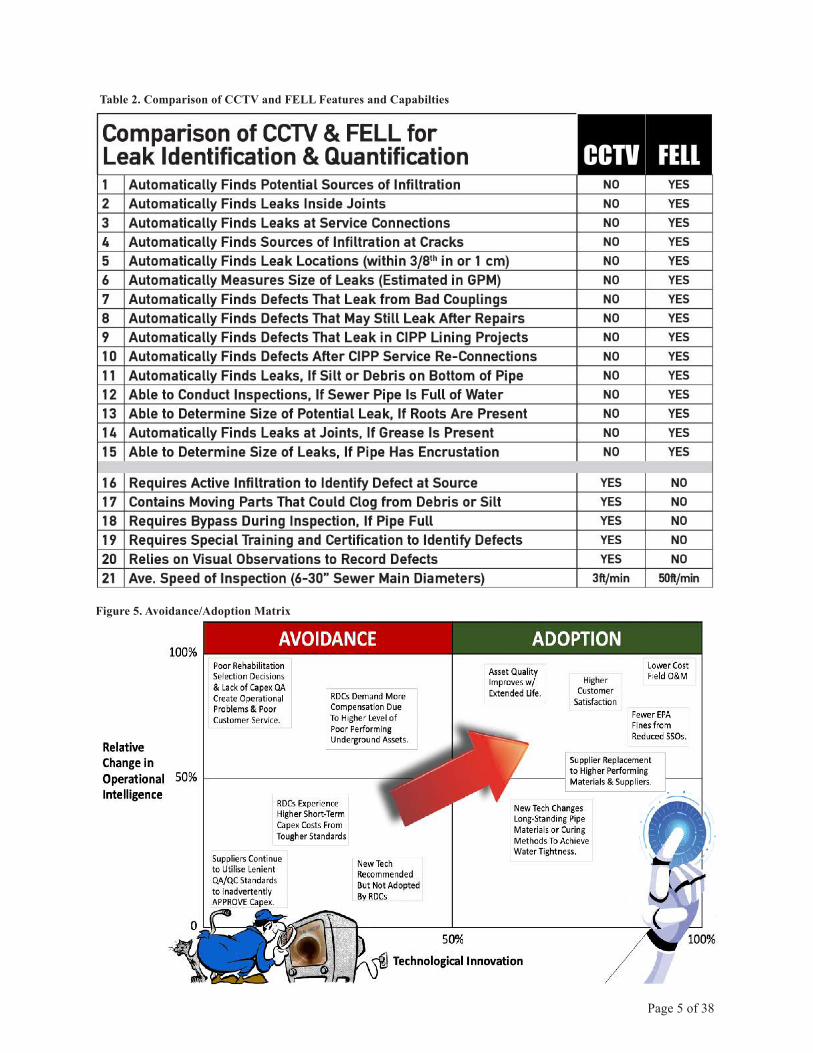
Table 2. Comparison of CCTV and FELL Features and Capabilties
tivity, also referred to as Focused Electrode Leak Location (FELL), as a new way to accurately and consistently test full-length non-conductive (i.e. non-metallic) pipes, for water tightness, a business case was pursued to conduct a field trial of the tech-nology in partnership with U.S.-based Electro Scan Inc. and its Australian subsidiary Electro Scan Aus-tralia Pty Ltd.
Working as a subcontractor to a Sydney Water ap-proved contractor, Aqua Assets Pty Ltd., six (6) locations were selected, as shown in Figure 1, to conduct detail field investigations, including com-parison with Sydney Water approved Closed-Circuit Television (CCTV) inspection, in accordance with current WSAA standards.
Subsequent to required Sydney Water induction and White Card certification, field work was undertaken from 6 December to 13 December 2019, with find-ings discussed in this report.
Page 6 of 38
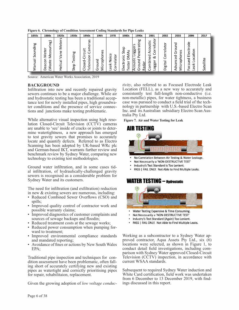
Figure 6. Chronology of Condition Assessment Coding Standards for Pipe Leaks
Source: American Water Works Association, 2019
Figure 7. Air and Water Testing for Leak
BACKGROUNDInfiltration into new and recently repaired gravity sewers continues to be a major challenge. While air and hydrostatic testing has been a traditional accep-tance test for newly installed pipes, high groundwa-ter conditions and the presence of service connec-tions and junctions make testing problematic.
While alternative visual inspection using high reso-lution Closed-Circuit Television (CCTV) cameras are unable to ‘see’ inside of cracks or joints to deter-mine watertightness, a new approach has emerged to test gravity sewers that promises to accurately locate and quantify defects. Referred to as Electro Scanning has been adopted by UK-based WRc plc and German-based IKT, warrants further review and benchmark review by Sydney Water, comparing new technology to existing test methodologies.
Ground water infiltration, and in some cases tid-al infiltration, of hydraulically-challenged gravity sewers is recognised as a considerable problem for Sydney Water and its customers.
The need for infiltration (and exfiltration) reduction in new & existing sewers are numerous, including:• Reduced Combined Sewer Overflows (CSO) and
spills;• Improved quality control of contractor work and
possible warranty claims;• Improved diagnostics of customer complaints and
sources of sewage backups and floodin;• Reduced treatment costs at the sewage works;• Reduced power consumption when pumping for-
ward to treatment;• Improved environmental compliance standards
and mandated reporting;• Avoidance of fines or actions by New South Wales
EPA;
Traditional pipe inspection and techniques for con-dition assessment have been problematic, often fall-ing short of accurately certifying new and existing pipes as watertight and correctly prioritising pipes for repair, rehabilitaion, replacement.
Given the growing adoption of low voltage conduc-
Page 7 of 38
Figure 8. Air and Water Testing for Leak
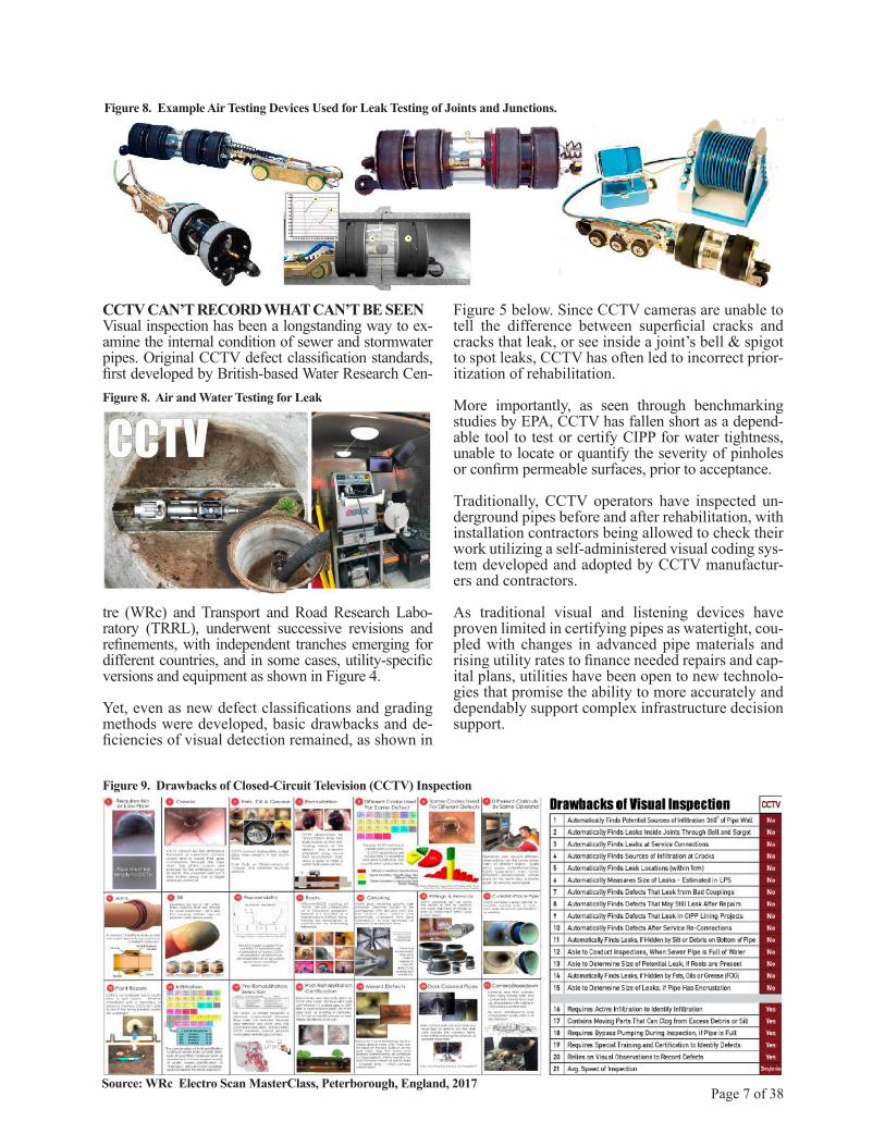
Figure 8. Example Air Testing Devices Used for Leak Testing of Joints and Junctions.
Figure 9. Drawbacks of Closed-Circuit Television (CCTV) Inspection
Source: WRc Electro Scan MasterClass, Peterborough, England, 2017
CCTV CAN’T RECORD WHAT CAN’T BE SEENVisual inspection has been a longstanding way to ex-amine the internal condition of sewer and stormwater pipes. Original CCTV defect classification standards, first developed by British-based Water Research Cen-
tre (WRc) and Transport and Road Research Labo-ratory (TRRL), underwent successive revisions and refinements, with independent tranches emerging for different countries, and in some cases, utility-specific versions and equipment as shown in Figure 4.
Yet, even as new defect classifications and grading methods were developed, basic drawbacks and de-ficiencies of visual detection remained, as shown in
Figure 5 below. Since CCTV cameras are unable to tell the difference between superficial cracks and cracks that leak, or see inside a joint’s bell & spigot to spot leaks, CCTV has often led to incorrect prior-itization of rehabilitation.
More importantly, as seen through benchmarking studies by EPA, CCTV has fallen short as a depend-able tool to test or certify CIPP for water tightness, unable to locate or quantify the severity of pinholes or confirm permeable surfaces, prior to acceptance.
Traditionally, CCTV operators have inspected un-derground pipes before and after rehabilitation, with installation contractors being allowed to check their work utilizing a self-administered visual coding sys-tem developed and adopted by CCTV manufactur-ers and contractors.
As traditional visual and listening devices have proven limited in certifying pipes as watertight, cou-pled with changes in advanced pipe materials and rising utility rates to finance needed repairs and cap-ital plans, utilities have been open to new technolo-gies that promise the ability to more accurately and dependably support complex infrastructure decision support.

Page 8 of 38
Figure 10. Low Voltage Conductivity Scientific Principle
Source: ASTM F2550 (2006, 2013, and 2018).
Grounding Stake
Crack orBreak
ElectricCurrent
Non-Conductive Pipe
Same Cable as CCTV Probe
VoltageSource
Low Resistance Path Through Ground
Figure 11. COMSOL® Multiphysics® depiction of Electro Scan’s narrowly focused electric beam able to assess 360o of pipe wall traveling at a speed of 15-20m per minute.
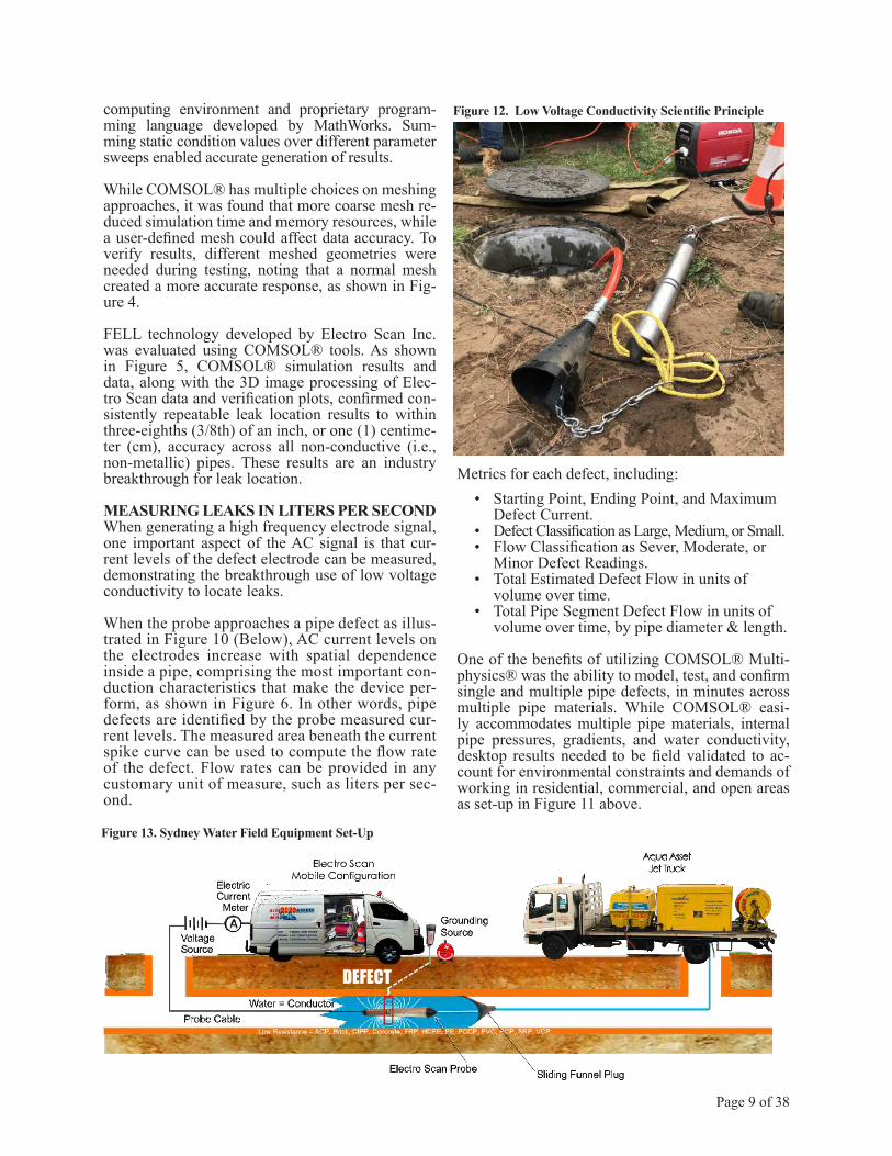
THE SCIENCE OF LOW VOLTAGECONDUCTIVITY TESTINGAfter a number of CIPP liner failures, during and directly after its warranty period, technical solu-tions were sought to create an accurate, cost-effec-tive, and repeatable way to reliably certify the water tightness of pipelines. Complicating matters were the seemingly endless combinations of pipe mate-rials, diameters, shapes, depths, lengths, gradients, soil types, and age profiles.
The science of using low voltage conductivity is straightforward. A similar application known as hol-iday testing, was already in use to evaluate protec-tive coatings for exposed pipes, rooftops, and res-ervoir linings. The technology need was for a low voltage equivalent to internally assess full-length, 360-degree pipe wall integrity while allowing exist-ing flow conditions during inspection.
Most sewer pipe materials such as brick, clay, plas-tic, concrete, and resin-based liners, are poor con-ductors of electrical current. As a result, if a defect exists in the wall of a pipe, then leakage of electri-cal current will indicate the location and size of the defect. The measured intensity and duration of the electrical signal emanating from the pipe can be cor-related to a flow rate in Gallons per Minute (GPM), whether or not water infiltration or exfiltration ac-tually occurs during the survey, without bypass re-quired.
An approach was developed by establishing a low, 12-volt electrical circuit with a 40 milliamp (mA) signal, using water as a conductor, which allowed two ends of the circuit to connect and close the loop, as depicted in Figure 3. Applied to an underground pipe, one side of the circuit would remain inside a non-conductive pipe (e.g., asbestos cement, brick, epoxy-coated ductile iron, high density polyeth-ylene, plastic, resin-based liner, vitrified clay pipe, etc.). Connected to a grounding stake, any defect current would need to travel to the surface to con-firm a corresponding pipe wall defect, or leak.
If the loop is never closed, whereby an electrical cir-cuit is closed, the pipe would be shown to have no defects. Conversely, if the loop is closed, whereby an electrical connection is made, then an opening or defect exists in the pipe wall, allowing a pathway from inside of the pipe to ground. Since water leak-age and electric current are highly correlated, the intensity and duration of measured current can pro-vide a specific defect size and corresponding flow rate in gallons per minute.
Utilizing desktop pipe simulation tools that could reliably model variable impedance of the electric circuit would be the first step. Confirming probe di-
mensions, power settings, grounding sources, data capture, repeatability of results, and precision of leak location would offer precise locational accura-cy. Important also to defect location is quantifying a leakage rate. Basic assumptions related to hydraulic head conditions on a defect and surrounding pipe burial soil conditions were made to develop a calcu-lation for a relative leakage rate that is not made by other existing leak location products.
Following the principle operation of AC circuits, a grounding source was needed to simulate a conduc-tive rod driven into the earth near the operation of the device to complete its circuit. The frequency of signal sources provided direction with regards to the system physics. In other words, modelling and thinking of electric fields, current and charge sourc-es were done under the assumption of steady state or “static” conditions. Analyzing electric fields and current densities were performed under several stat-ic conditions including, but not limited to, pipe size, pipe material, defect size, voltage levels, and defect location along the pipe, relative to the probe.
As illustrated in Figure 9 (Below) electrostatic op-erational properties and parameters were modeled, analyzed, and plotted using COMSOL® Multiph-ysics® and MATLAB, a multi-paradigm numerical
Page 9 of 38
Figure 12. Low Voltage Conductivity Scientific Principle
Figure 13. Sydney Water Field Equipment Set-Up
DEFECT
computing environment and proprietary program-ming language developed by MathWorks. Sum-ming static condition values over different parameter sweeps enabled accurate generation of results.
While COMSOL® has multiple choices on meshing approaches, it was found that more coarse mesh re-duced simulation time and memory resources, while a user-defined mesh could affect data accuracy. To verify results, different meshed geometries were needed during testing, noting that a normal mesh created a more accurate response, as shown in Fig-ure 4.
FELL technology developed by Electro Scan Inc. was evaluated using COMSOL® tools. As shown in Figure 5, COMSOL® simulation results and data, along with the 3D image processing of Elec-tro Scan data and verification plots, confirmed con-sistently repeatable leak location results to within three-eighths (3/8th) of an inch, or one (1) centime-ter (cm), accuracy across all non-conductive (i.e., non-metallic) pipes. These results are an industry breakthrough for leak location.
MEASURING LEAKS IN LITERS PER SECONDWhen generating a high frequency electrode signal, one important aspect of the AC signal is that cur-rent levels of the defect electrode can be measured, demonstrating the breakthrough use of low voltage conductivity to locate leaks.
When the probe approaches a pipe defect as illus-trated in Figure 10 (Below), AC current levels on the electrodes increase with spatial dependence inside a pipe, comprising the most important con-duction characteristics that make the device per-form, as shown in Figure 6. In other words, pipe defects are identified by the probe measured cur-rent levels. The measured area beneath the current spike curve can be used to compute the flow rate of the defect. Flow rates can be provided in any customary unit of measure, such as liters per sec-ond.
Metrics for each defect, including:• Starting Point, Ending Point, and Maximum Defect Current.• Defect Classification as Large, Medium, or Small.• Flow Classification as Sever, Moderate, or Minor Defect Readings.• Total Estimated Defect Flow in units of volume over time.• Total Pipe Segment Defect Flow in units of volume over time, by pipe diameter & length.
One of the benefits of utilizing COMSOL® Multi-physics® was the ability to model, test, and confirm single and multiple pipe defects, in minutes across multiple pipe materials. While COMSOL® easi-ly accommodates multiple pipe materials, internal pipe pressures, gradients, and water conductivity, desktop results needed to be field validated to ac-count for environmental constraints and demands of working in residential, commercial, and open areas as set-up in Figure 11 above.
Page 10 of 38
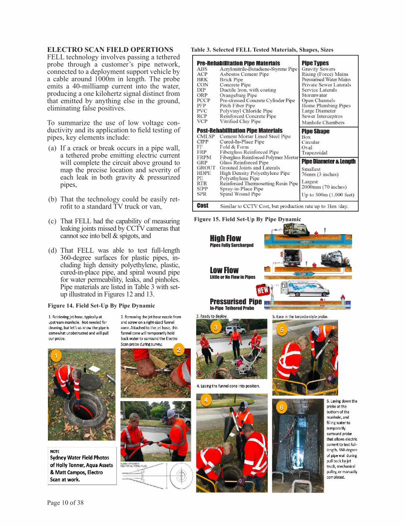
Table 3. Selected FELL Tested Materials, Shapes, Sizes
Figure 15. Field Set-Up By Pipe Dynamic
High FlowPipes Fully Surcharged
Low FlowLittle or No Flow in Pipes
Pressurised PipeIn-Pipe Tethered ProbeFigure 14. Field Set-Up By Pipe Dynamic
ELECTRO SCAN FIELD OPERTIONSFELL technology involves passing a tethered probe through a customer’s pipe network, connected to a deployment support vehicle by a cable around 1000m in length. The probe emits a 40-milliamp current into the water, producing a one kilohertz signal distinct from that emitted by anything else in the ground, eliminating false positives.
To summarize the use of low voltage con-ductivity and its application to field testing of pipes, key elements include:(a) If a crack or break occurs in a pipe wall,
a tethered probe emitting electric current will complete the circuit above ground to map the precise location and severity of each leak in both gravity & pressurized pipes,
(b) That the technology could be easily ret-rofit to a standard TV truck or van,
(c) That FELL had the capability of measuring leaking joints missed by CCTV cameras that cannot see into bell & spigots, and
(d) That FELL was able to test full-length 360-degree surfaces for plastic pipes, in-cluding high density polyethylene, plastic, cured-in-place pipe, and spiral wound pipe for water permeability, leaks, and pinholes. Pipe materials are listed in Table 3 with set-up illustrated in Figures 12 and 13.

Page 11 of 38
The Electro Scan system’s adaptive design allows for quick, simple transitions between CCTV and Electro Scan configurations. The Electro Scan probe connects to the reel with the same type of plug the CCTV camera uses. A switchover box allows for data switching to either the CCTV Terminal or the Electro Scan Controller, and then to the Computer for viewing and storage.
What Equipment Was Used in Sydney Water Electro Scan Trial?
FELL
CCTV
Figure 16. Field Set-Up Configuration for Sydney Water Electro Scan Trial
Electro ScanES-620 Mobile Components
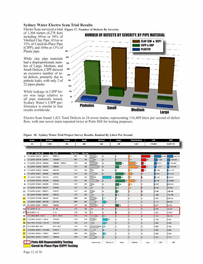
Sydney Water Electro Scan Trial Results
Figure 18. Sydney Water Trial Project Survey Results, Ranked By Liters Per Second
Page 12 of 38
123456789
101112131415161718192021222324
NUMBER OF DEFECTS BY SEVERITY, BY PIPE MATERIALCLAY (EW & VCP)CIPP & SRPPLASTIC
Pinholes Small Medium Large
Electro Scan surveyed a total of 1,304 meters (4,278 feet) including 691m or 54% of Vitrified Clay Pipe, 431m or 33% of Cured-In-Place Pipe (CIPP), and 169m or 13% of Plastic pipe.
While clay pipe materials had a disproportionate num-ber of Large, Medium, and Small Defects, CIPP showed an excessive number of to-tal defects, primarily due to pinhole leaks, with only 2 of 22 pipes plastic.
While leakage in CIPP lin-ers was large relative to all pipe materials tested, Sydney Water’s CIPP per-formance is similar to line results worldwide.
Electro Scan found 1,421 Total Defects in 24 sewer mains, representing 116,409 liters per second of defect flow, with one sewer main repeated twice at Potts Hill for testing purposes.
Potts Hill Repeatability Testing
Figure 17. Number of Defects By Severity
Cured-In-Place Pipe (CIPP) Testing

TOTAL LPS0.05 34.17
Page 13 of 38
Figure 20. Sydney Water Trial Project Survey Matrix
The FELL Electro Scan trail project was limited in its scope and, therefore may not be representative of Sydney Water’s total network, leak profile, age, pipe condition, or thoroughness of current inspec-tion techniques or contractor performance; howev-er, even the limited scope of work indicates several drawbacks with current condition assessment prac-tices.
Sydney Water condition assessment, inspection, and certification standards are similar to other water util-ities survey by Electro Scan Inc.
Electro Scan Inc., and its wholly-owned British, German, and Canadian subsidiaries have cumula-tive assessment of over 1,200 km (4 million feet)of pipes using its patented low voltage conductivity technology, with all results stored on its proprietary Amazon Web Services cloud-based CriticalSew-ers® cloud application developed and supported by California-based Hansen Analytics LLC.
While additional field testing is warranted to under-stand scope and significance of its finding, especially before any across-the-board implementation, imme-
diate need appears necessary in support of Sydney Water’s CIPP acceptance program and dry weather & wet weather infiltration assessment program.
As shown on the following page, twenty-four (24) sewer mains surveyed as part of its trial project in-cluded Clay, CIPP, and Plastic pipes, as follows:
Meters Defects l/sClay1 706 994 107.44CIPP 429 402 8.74PVC 169 25 0.23 Total 1,304 1,421 116.41
Table 4. Number of Meters, Defects and Defect Flow in l/s
It should be noted that while defects counts and l/s defect flows for clay pipe appears consistent with older pipes, but defects found in newly installed CIPP appears excessive.
1 Clay pipe includes earthenware and vitrified clay pipe.

Sydney Water Electro Scan Trial Results – By Pipe Material
Page 14 of 38
Figure 20. Cured-In-Place Pipe (CIPP), including 1 Spiral Wound Pipe, Ranked By Liters Per Second
12345678
123456789
1011121314
Figure 19. Clay Pipe, Ranked By Liters Per Second
Figure 21. Plastic Pipe, Ranked By Liters Per Second
12
Earthenware & Vitrified Clay Pipe
Cured-In-Place Pipe
Pipe Leakage By Liters Per SecondLiters Per Second / Meter
EW EW

360360oo Unfolded Pipe ViewUnfolded Pipe View
Can’t See Leaks In Can’t See Leaks InJoints or Connections.Joints or Connections.
Panorama CCTV Camera
Bell & Spigot Jointswith Compression Gaskets
Cracks & FracturesCracks & Fractures
CCTV Not Able To Determine CCTV Not Able To Determine LeakageLeakage
Open-Ended Joints
Clay Pipe AssessmentWhile Sydney Water recommends other pipe materials that may be better suited for specific locations, clay pipe, including earthenware (EW), salt glazed ware (SGW),
and vitrified clay (VC) pipe, which represents the most significant percentage of sewer pipe material in the util-ity’s service area, and not capable of adequately assess-ing leak profiles at cracks or joints.
Page 15 of 38
Figure 22. FELL Inspection of Bell & Spigot Joints Figure 23. FELL Inspection of Open Ended Joints
Figure 24. Example CCTV Inspection of Cracks Figure 25. Example IBAK Panorama CCTV of Sewer
InadequateClamping or
Restraint DuringFusion
Out of Round
Flat Spot
Melt Out
Leaking JointLeaking JointMissed ByMissed By
CCTVCCTV
Leaking JointLeaking JointMissed ByMissed By
CCTVCCTV
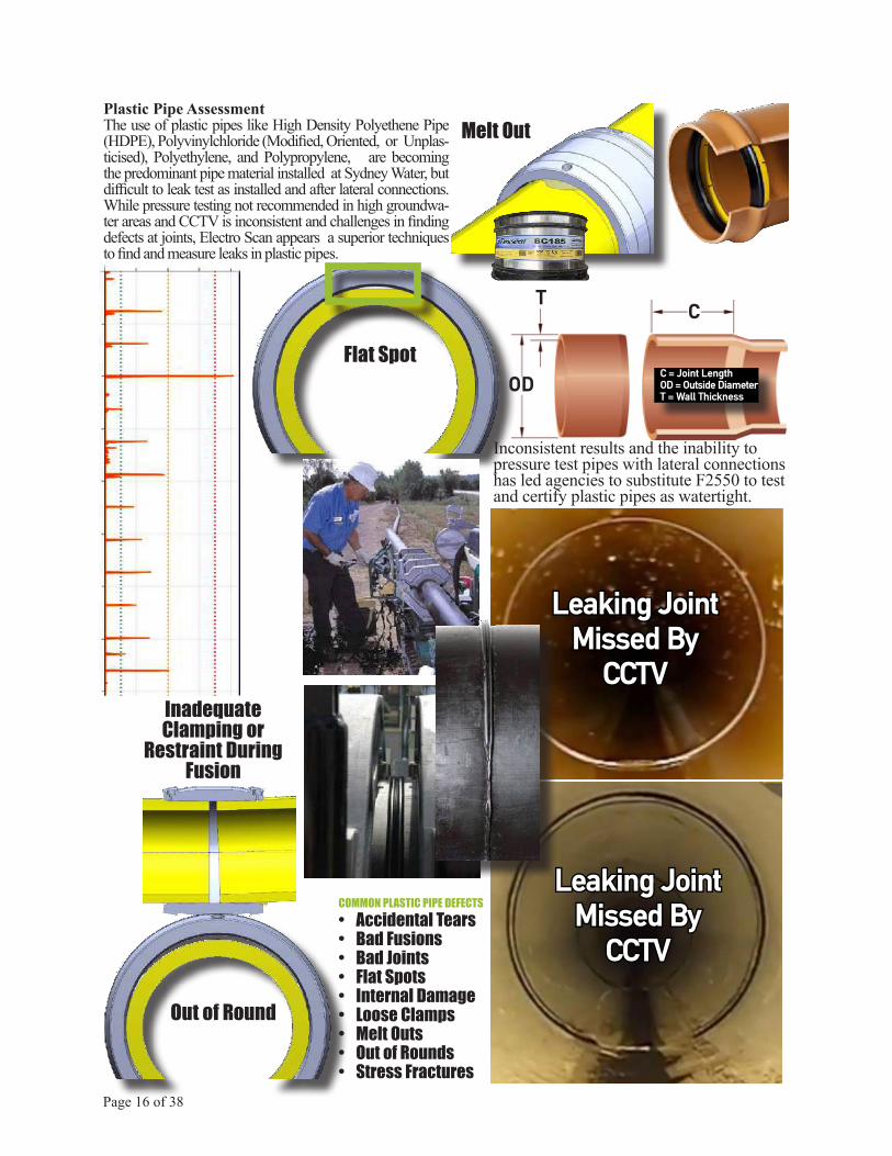
Inconsistent results and the inability to pressure test pipes with lateral connections has led agencies to substitute F2550 to test and certify plastic pipes as watertight.
COMMON PLASTIC PIPE DEFECTS• Accidental Tears• Bad Fusions• Bad Joints• Flat Spots• Internal Damage• Loose Clamps• Melt Outs• Out of Rounds• Stress Fractures
C
OD
T
C = Joint LengthOD = Outside DiameterT = Wall Thickness
Plastic Pipe AssessmentThe use of plastic pipes like High Density Polyethene Pipe (HDPE), Polyvinylchloride (Modified, Oriented, or Unplas-ticised), Polyethylene, and Polypropylene, are becoming the predominant pipe material installed at Sydney Water, but difficult to leak test as installed and after lateral connections. While pressure testing not recommended in high groundwa-ter areas and CCTV is inconsistent and challenges in finding defects at joints, Electro Scan appears a superior techniques to find and measure leaks in plastic pipes.
Page 16 of 38

Page 17 of 38
Scan #1 Upstream
Scan #2 Downstream
Scan #3 Upstream
Scan #4 Downstream
Figure 26. Repeatability Testing
Figure 27. New Release of Cloud-Based CIPP Leak Assessment Application
Peter HenleyWRc
FELL-IKTTESTING
CURED-IN-PLACE PIPE (CIPP) TESTING BY IKT, WRc plc, & ELECTRO SCAN Much work on the testing and inspection of CIPP liners has been spearheaded by the Institut für Unterir-dische Infrastruktur (IKT), Gelsenkirchen, Germany. In 2016, IKT invited British-based Water Research Centre (WRc Plc) and American-based Electro Scan Inc. to participate on IKT’s short-liner CIPP study. Conducting field and laboroatory testing, including hydrostatic pres-sure testing and FELL testing util-ising Electro Scan certified equip-ment, initial results were published in October 2019, with final results to be published upon approval by the German government.
A key finding of IKT’s work was the consistent, repeatable test results of Electro Scan, which it had assessed as part of earlier version in 2001. While key read-ings demonstrated remarkable repeatability, IKT further recom-mended that additional software developments be undertaken to quantify pinholes leakage (less than 0.1 gallon per minute), as shown in Figures 26 & 27.
CIPP
RECOMMENDED ACCEPTANCE GUIDELINES
Page 18 of 38
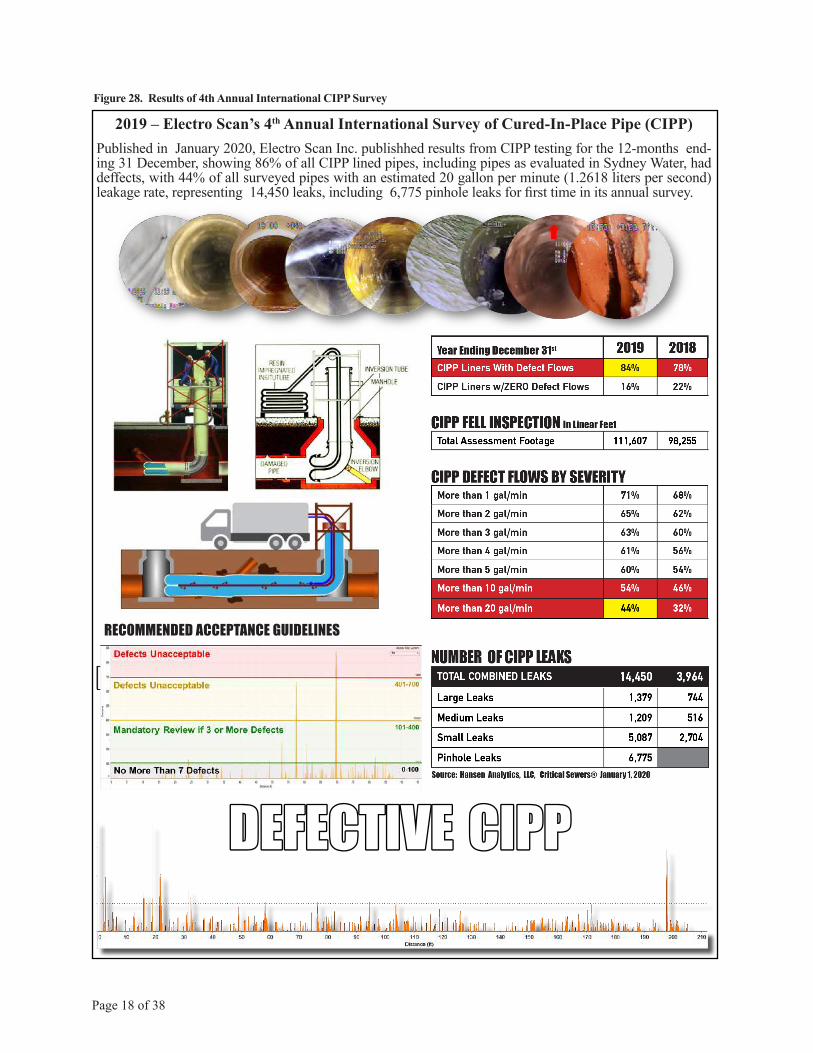
Figure 28. Results of 4th Annual International CIPP Survey
2019 – Electro Scan’s 4th Annual International Survey of Cured-In-Place Pipe (CIPP)Published in January 2020, Electro Scan Inc. publishhed results from CIPP testing for the 12-months end-ing 31 December, showing 86% of all CIPP lined pipes, including pipes as evaluated in Sydney Water, had deffects, with 44% of all surveyed pipes with an estimated 20 gallon per minute (1.2618 liters per second) leakage rate, representing 14,450 leaks, including 6,775 pinhole leaks for first time in its annual survey.
DEFECTIVE CIPPDEFECTIVE CIPP

1. POTTS HILL
Page 19 of 38
Sydney Water’s outdoor test facility on Lewis Street was the location for the first tri-al of Electro Scan’s FELL technology. Working with authorised contractor NWS-based Aqua Assets Pty Ltd., Sydney Water training was completed with Induction Cards duly certified, prior to conducting work on Sydney Water premises.
A 16m length 150mm diam-eter test bed was installed to allow vendors to test their unpackaged equipment and allow other field personnel to receive ‘hands-on’ famil-iarity with equipment config-urations.
Sydney Water’s test bed represented a 10m Vitrified Clay Pipe (VCP) segment, followed by a 2m Polyvinyl Chloride (PVC) section, fol-lowed by a 4m VCP sectional.
Standard plastic joints were used to connect each VCP Open Ended Joint, while Ferncos fittings were used to secure each end of the PVC sectional pipe.
CCTV vs. FELL Results ComparisonA key question of Sydney Water’s Busi-ness Case was whether significant differ-ence existed between visual identifica-tion of defects from the operation of a high resolution CCTV camera versus ma-chine identification of defects from the operation of FELL equipment. Other obvious comparisons include ease of use, survey time & speed, data genera-
tion & storage, and repeatability. The Electro Scan FELL survey was com-pleted first, including a second scan to demonstrate its data repeatability.
Potts Hill, Lewis Street training facility.
Sydney Water trial test bed for pipe evaluations.
Temporary Filling of Water from Jet Hose (Below).
CCTV was conducted after FELL, with the seasoned, certified CCTV operator aware of the comparisonand need to callout each defect.

Page 20 of 38
As shown above in Figure 16 (Above), CCTV recorded three (3) defect locations, including (a) displaced joint at 2,71m, (b) longitudinal fracture @10.22m, and (c) circumferential fracture @ 11.16m, with both defects at (b) and (c) placed by Sydney Water staff. Once fully set-up with the camera positioned in the pipe CCTV inspection took 13 minutes, 15 seconds to complete its inspection.
In contrast, FELL recorded eleven (11) defect locations, including leak locations at joints, defects at both changes in mate-rial, and both previously installed defects
V
V
V
at longitudinal and circumferential locations.
Two (2) of the 11 defects may have been influenced by a metallic flange in each of the ferno fittings, but sep-aration of FELL results, indicates that ‘no impact’ was made on any other defects identified.
Once fully set-up with the FELL probe positioned in the pipe, FELL took 4 minutes, 18 seconds to com-plete its survey.
NOTEElectro Scan completed a
second survey, immediately fol-lowing its first scan successfully
demonstrating its repeatability.
Page 21 of 38
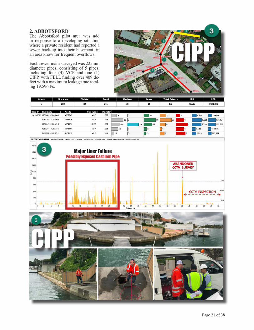
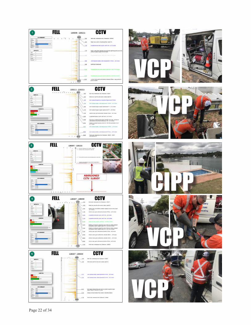
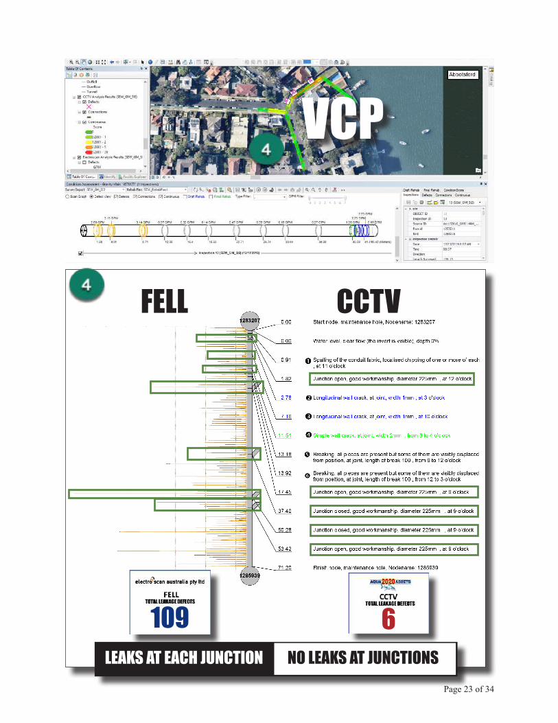
2. ABBOTSFORDThe Abbotsford pilot area was add in response to a developing situation where a private resident had reported a sewer back-up into their basement, in an area know for frequent overflows.
Each sewer main surveyed was 225mm diameter pipes, consisting of 5 pipes, including four (4) VCP and one (1) CIPP, with FELL finding over 409 de-fect with a maximum leakage rate total-ing 19.596 l/s.
CIPP
CIPP
Major Liner FailurePossibly Exposed Cast Iron Pipe
Page 22 of 34
CIPP
VCP
VCP
VCPVCP
Page 23 of 34
VCP
6109
FELL CCTV
LEAKS AT EACH JUNCTION NO LEAKS AT JUNCTIONS

Page 24 of 38
3. BALGOWLAH HEIGHTSDespite a collapse found by CCTV in #1, difficult to access manhole entry was easily overcome to allow both CCTV and FELL inspections; how-ever FELL automatically surveyed leaks at nearly every VCP pipe joint, fractures, and junctions.
With FELL and CCTV inspections beginning at a manhole located in a residential backyard patio, with a steep slope, the jet truck was posi-tioned at the downstream manhole and successfully jetted up to the up-stream manhole.
VCP
FELL CCTV
3140
Page 25 of 38
VCP
Page 26 of 38
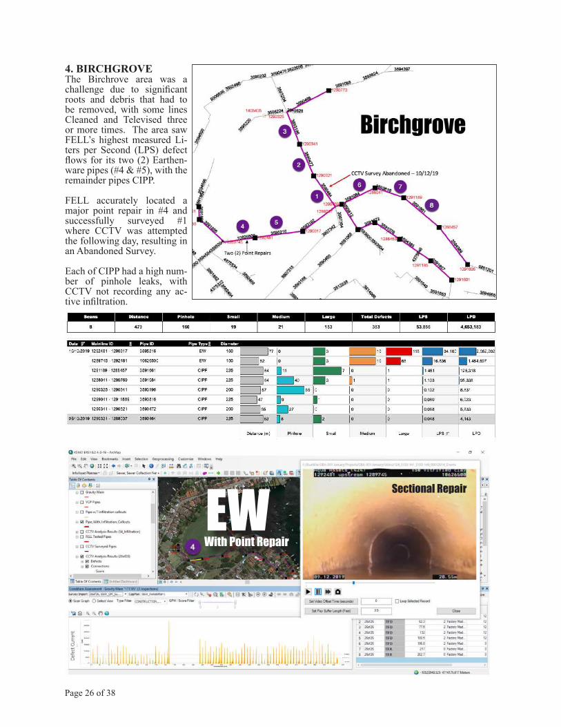
4. BIRCHGROVEThe Birchrove area was a challenge due to significant roots and debris that had to be removed, with some lines Cleaned and Televised three or more times. The area saw FELL’s highest measured Li-ters per Second (LPS) defect flows for its two (2) Earthen-ware pipes (#4 & #5), with the remainder pipes CIPP.
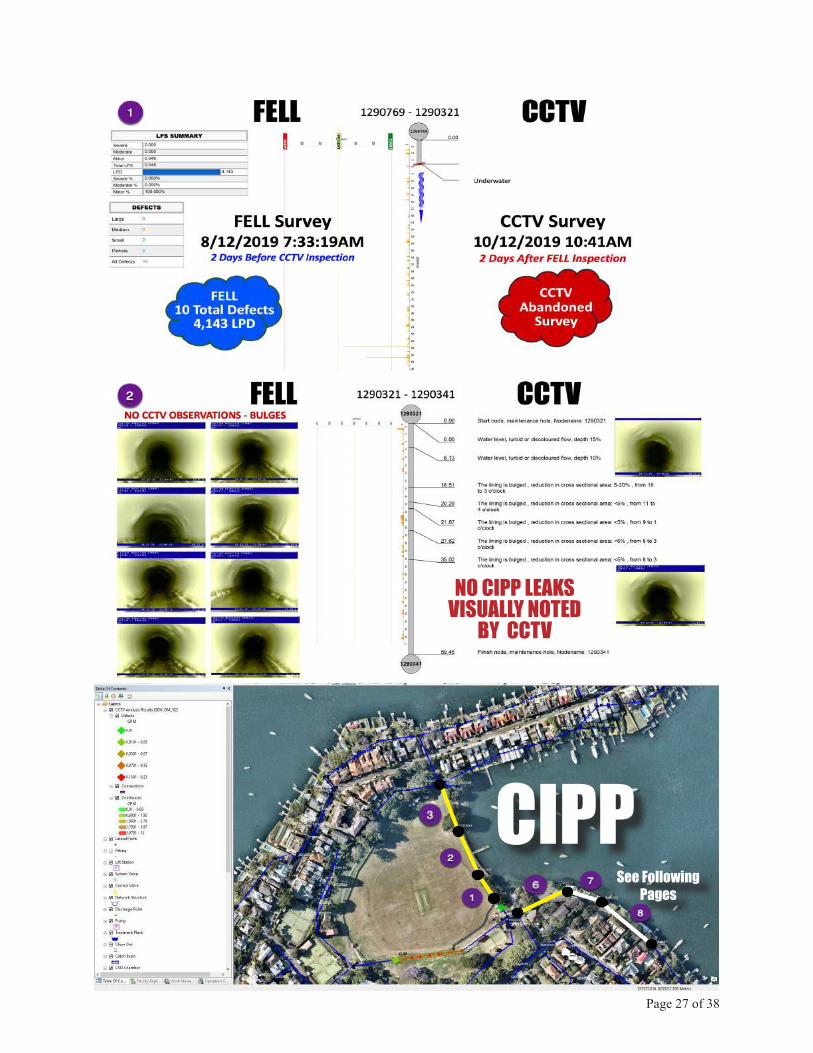
FELL accurately located a major point repair in #4 and successfully surveyed #1 where CCTV was attempted the following day, resulting in an Abandoned Survey.
Each of CIPP had a high num-ber of pinhole leaks, with CCTV not recording any ac-tive infiltration.
EWWith Point Repair
Sectional Repair
Page 27 of 38
CIPPSee Following Pages
NO CIPP LEAKSVISUALLY NOTED
BY CCTV

Two CCTV Contractors Survey Same CIPP Liner, 6-Days Apart
28 November 20194 December 2019STR GRADE 1 STR GRADE 5
CCTV ABOVE• No matching CCTV Observations• 17 vs. 31 CCTV Observations.• No leaks recorded by either TV Contractor.
Asset No. 3593816 | Start MH 1291189 - Finish MH 1299041
CIPPCIPP
FELL BELOW• 9 PINHOLE LEAKS• 1 SMALL LEAK• LPS - 0.8 | LPD - 6,923
Page 28 of 38
CCTV Contractor #1 CCTV Contractor #2
CCTV Contractor #2
CCTV Contractor #1

219
FELL CCTVCIPPCIPPAsset No. 3591661 | Start MH 1291189 - Finish MH 1288457
Page 29 of 38
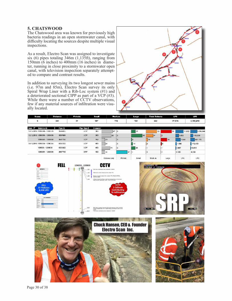
5. CHATSWOODThe Chatswood area was known for previously high bacteria readings in an open stormwater canal, with difficulty locating the sources despite multiple visual inspections.
As a result, Electro Scan was assigned to investigate six (6) pipes totaling 346m (1,135ft), ranging from 150mm (6 inches) to 400mm (16 inches) in diame-ter, running in close proximity to a stormwater open canal, with television inspection separately attempt-ed to compare and contrast results.
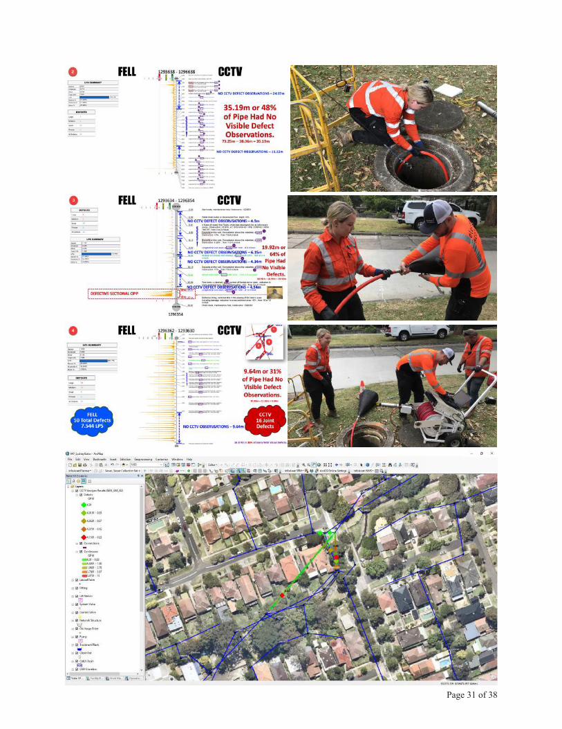
In addition to surveying its two longest sewer mains (i.e. 97m and 85m), Electro Scan survey its only Spiral Wrap Liner with a Rib-Loc system (#1) and a deteriorated sectional CIPP as part of a VCP (#3). While there were a number of CCTV observations, few if any material sources of infiltration were visu-ally located.
SRP
Page 30 of 38
Chuck Hansen, CEO & FounderElectro Scan Inc.
Page 31 of 38
Page 32 of 38
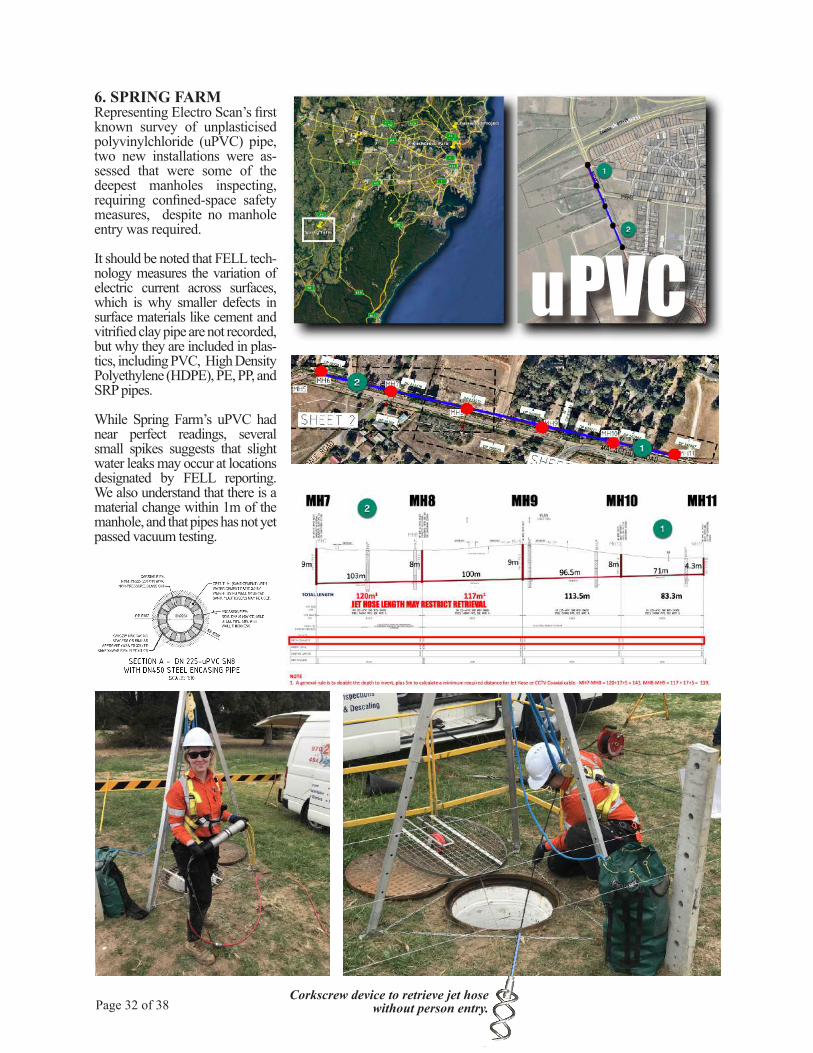
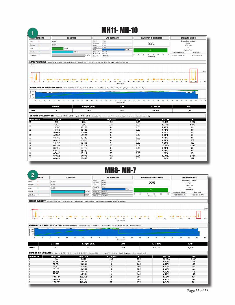
6. SPRING FARMRepresenting Electro Scan’s first known survey of unplasticised polyvinylchloride (uPVC) pipe, two new installations were as-sessed that were some of the deepest manholes inspecting, requiring confined-space safety measures, despite no manhole entry was required.
It should be noted that FELL tech-nology measures the variation of electric current across surfaces, which is why smaller defects in surface materials like cement and vitrified clay pipe are not recorded, but why they are included in plas-tics, including PVC, High Density Polyethylene (HDPE), PE, PP, and SRP pipes.
While Spring Farm’s uPVC had near perfect readings, several small spikes suggests that slight water leaks may occur at locations designated by FELL reporting. We also understand that there is a material change within 1m of the manhole, and that pipes has not yet passed vacuum testing.
uPVC
Corkscrew device to retrieve jet hosewithout person entry.
Page 33 of 38
MH11- MH-10
MH8- MH-7
Page 34 of 38
DECISION SUPPORTPrioritizing and grouping pipes into comprehensive sewer rehabilitation and replacement projects is complex and challenging.
Often involving a multi-tude of variables and com-plex ongoing analyses, risk is often defined as:
= [(Likelihood of failure) x (Consequence of failure)]
Where the likelihood of fail-ure (LoF) is the probability of an asset failure occur-ring, and consequence of failure (CoF) is defined as the relative impact on the level of service resulting from a specific asset failure.
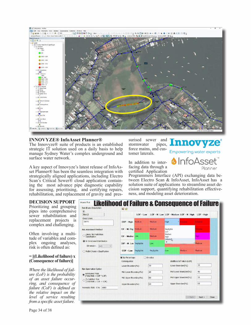
INNOVYZE® InfoAsset Planner®The Innovyze® suite of products is an established strategic IT solution used on a daily basis to help manage Sydney Water’s complex underground and surface water network.
A key aspect of Innovyze’s latest release of InfoAs-set Planner® has been the seamless integration with strategically aligned applications, including Electro Scan’s Critical Sewer® cloud application contain-ing the most advance pipe diagnostic capability for assessing, prioritising, and certifying repairs, rehabilitation, and replacement of gravity and pres-
surised sewer and stormwater pipes, force mains, and cus-tomer laterals.
In addition to inter-facing data through a certified Application Programmers Interface (API) exchanging data be-tween Electro Scan & InfoAsset, InfoAsset has a solution suite of applications to streamline asset de-cision support, quantifying rehabilitation effective-ness, and modeling asset deterioration.
Likelihood of Failure & Consequence of Failure
Page 35 of 38
DECISION TREE
REHABILITATION SELECTION
DETERIORATION
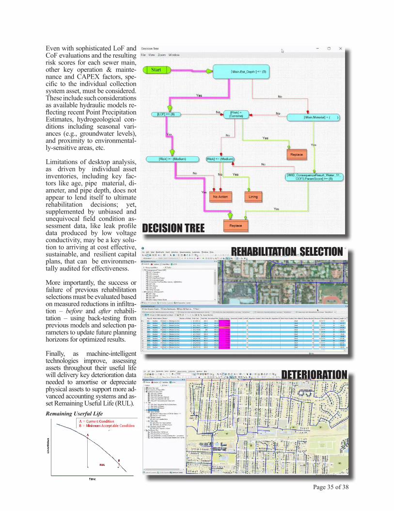
Even with sophisticated LoF and CoF evaluations and the resulting risk scores for each sewer main, other key operation & mainte-nance and CAPEX factors, spe-cific to the individual collection system asset, must be considered. These include such considerations as available hydraulic models re-flecting recent Point Precipitation Estimates, hydrogeological con-ditions including seasonal vari-ances (e.g., groundwater levels), and proximity to environmental-ly-sensitive areas, etc.
Limitations of desktop analysis, as driven by individual asset inventories, including key fac-tors like age, pipe material, di-ameter, and pipe depth, does not appear to lend itself to ultimate rehabilitation decisions; yet, supplemented by unbiased and unequivocal field condition as-sessment data, like leak profile data produced by low voltage conductivity, may be a key solu-tion to arriving at cost effective, sustainable, and resilient capital plans, that can be environmen-tally audited for effectiveness.
More importantly, the success or failure of previous rehabilitation selections must be evaluated based on measured reductions in infiltra-tion – before and after rehabili-tation – using back-testing from previous models and selection pa-rameters to update future planning horizons for optimized results.
Finally, as machine-intelligent technologies improve, assessing assets throughout their useful life will delivery key deterioration data needed to amortise or depreciate physical assets to support more ad-vanced accounting systems and as-set Remaining Useful Life (RUL).Remaining Userful Life

Page 36 of 38
SUMMARYIn general, any new product, business process, or professional service that becomes a viable solution for the water industry, must satisfy five (5) key requirements, including:
1. Have ability to demonstrate consistently superior and unambiguous results as compared to current methodologies,2. Prove its capability to operate on a cross-section of assets, either achieving mini-mum or better-than-current methodologies,3. Represent an overwehlming value for money,4. Have a reputable local representative or authorized service provider, and5. Possess valid commercial/market/product/technical references that can be corroborated third party, unimpeachable sources.
TRIAL ELECTRO SCAN TRIAL PROJECTAs stated earlier the goal & objective of Sydney Wa-ter’s Trial Electro Scan Project was to test and docu-ment the practical application, field operation, and ease of reporting of Low Voltage Conductivity also known by the US EPA as Focused Electrode Leak Location (FELL) technology, utilising ASTM F2550-13 (2018), compared to traditional Closed-Circuit Television (CCTV) utilising WSA 05—2008 2.2 Conduit Inspec-tion Reporting Code of Australia standards, in a vari-ety of ”live” Sydney Water in-field conditions.
KEY QUESTIONDoes FELL technology deliver repeatable leak location and severity measurements not provided by traditional CCTV visual inspection? Can FELL technology be used to more accurately locate infiltration and exfiltration? What are FELL’s advantages & disadvantages to current operations? How should new (possible) quality standards be introduced during start-up & operation of Sydney Wa-ter’s Regional Delivery Consortium (RDC)?
ADVANTAGES OF LOW VOLTAGE-BASED FELL INSPECTION1. Accurately quantify leaks in liters per second.2. Automatically finds precise pipe location (1cm).3. Unbiased, unambiguous, repeatable results.4. Tested by American EPA, British WRc, German IKT, and Japanese JASCOMA.5. Average 2-3x faster than CCTV.6. No third-party data interpretation required.7. Approved for gravity sewers & pressurized pipes.8. Able to test rising mains (i.e. force mains).9. Able to test siphons.10. Able to test small (76mm) & large (2000mm) diameter pipes.11. Bypass pumping not required.12. Tests joints, including bell & spigot & open ended.
13. Tests customer connections and junctions.14. Creates baseline LPS Pipe Rating, Before Rehabilitation, for comparison After15. Tests CIPP & Post-Rehab % Effectiveness16. Referenced in EPA Consent Decrees17. ASTM F2550, 3rd Ed. 201818. AWWA M77, 1st Ed. 201919. Data in cloud, 10min or less, worldwide20. Add FELL to standard CCTV vans21. CCTV Kits available for Aries, Cues, IBAK, iPEK, Rausch, and other CCTV devices.22. Masterclass by WRc, developers of NASSCO codes.23. Utilized by IKT in recent CIPP study.24. Integrates w/Innovyze® InfoAsset®.
While the last question may be discussed in another venue, preliminary field results tend to answer to previ-ous questions appeared to be answered in the affirma-tive, and in many cases answered in a rather convinc-ing and unequivocal manner.
KEY FINDINGSEvaluation of the Sydney Water Potts Hill’s Test Pipe observed that FELL technology successfully detected both pre-arranged defects, similar to CCTV inspec-tion; however, FELL technology. Additionally, identi-fied and measured numerous other defects at material changes transitioning from clay pipe-to-plastic pipe, and defects at each joint.
In Chatswood, numerous sources of potential exfiltra-tion were identified in close proximity to a local river bed, not seen by CCTV, including defects in a Spiral Wrap Pipe.
In Birchgrove, an area of persistent tidal and wet weather infiltration (despite significant rehabilita-tion), found severe defects in recently lined cast iron pipes. One pipe where CCTV was attempted, but abandoned due to a significant bulge in Cured-In-Place Pipe (CIPP) liner, was successfully scanned in a single set-up by. FELL.
Customer Complaint sewer overflow -related locations in Abbotsford and Balgowlah Heights found numerous defects not found by CCTV, including a CIPP lined pipe abandoned by. CCTV and successfully survey by FELL.
New Unplastised Plastic Pipe (uPVC) evaluated in Spring Farm, already undergoing vacuum air testing, confirmed one pipe with no significant defects and one pipe with a single significant defect for a new pipe.
This trial project may have a possible significant im-pact on the future way Sydney Water determines pipe condition, especially for water tightness.
Page 37 of 38
REFERENCESAddressing the Shortcomings of a Sampling Strategy in CIPP Quality Assurance Programs, Tony Araujo and Po-Szu (Bruce) Yao, P.Eng., Paragon Systems Testing, Concord, Ontario, CANADA, NASTT 2019 No-Dig, Chicago, IL, March 2019.
ASTM F1216-09 and F1216-16, Standard Practice for Reha-bilitation of Existing Pipelines and Conduits by the Inversion and Curing of a Resin-Impregnated Tube.
ASTM F2550-06 and F2550-13 (2018), Standard Practice for Locating Leaks in Sewer Pipes By Measuring the Variation of Electric Current Flow Through the Pipe Wall.
Generational Thinking In Water Management, Water Online, By Kevin Westerling, @KevinOnWater, July 26, 2017.
Guide for Evaluating Capacity, Management, Operation, and Maintenance (CMOM) Programs at Sanitary Sewer Collection Systems, United States Environmental Protection Agency, Of-fice of Enforcement and Compliance Assurance (2224A), EPA 305-B-05-002, www.epa.gov, January 2005.
IKT-Liner Report 2018, Dipl.-Ök. Roland W. Waniek, Dipl.-Ing. Dieter Homann, Barbara Grunewald, M.Sc. IKT - Institute for Underground Infrastructure GmbH, Exterbruch 1,45886 Gelsenkirchen , Germany,
Retrospective Evaluation of Cured-in-Place Pipe Technology for Municipal Gravity Sewer Rehabilitation, Allouche, E., L. Wang, R. Sterling, And A. Selvakumar. EPA/600/R-12/004|-January 2012.
Operation and Maintenance of Wastewater Collection Systems, Volume I, Seventh Edition, ISBN 978-1-59371-066-8.
The Need to Quantify Pre- and Post-Rehabilitation Effective-ness, Chuck Hansen, Managing Partner, Hansen Invesment Holdings, LLC, October 2014.
USEPA Sewer Electro Scan Field Demonstration Revisited, 2013, Terry Moy, Manager, Program Management and Engi-neering, Clayton County Water Authority, 1600 Battle Creek Road, Marrow, GA 30260, USA, Charles G. Wilmut, Vice President, Burgess and Niple, 11117 Shady Trail, Dallas, TX 75229, USA, and Robert J. Harris, President, Leak Busters Inc, 3157 Bentley Drive Rescue, CA 95672, USA.
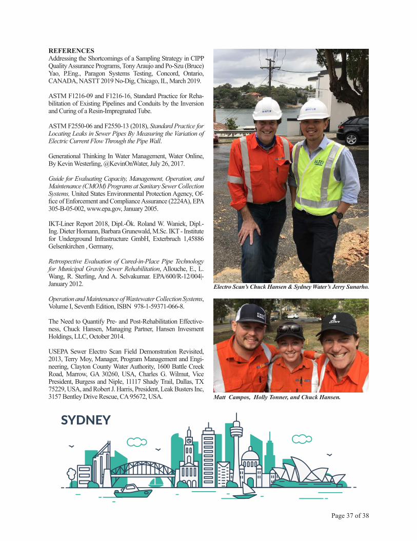
Electro Scan’s Chuck Hansen & Sydney Water’s Jerry Sunarho.
Matt Campos, Holly Tonner, and Chuck Hansen.

Chuck Hansen, [email protected]. Hansen is currently Chairman and Chief Executive Officer of Electro Scan Inc. and Managing Director of Hansen Analytics LLC, Sacramento, California, USA, with nearly 40 years supplying advanced asset management solutions to over 2,000 sewer & water agencies worldwide. In 1995, Hansen was selected by the Association of Local Government Engineers of New Zealand (AL-GENZ) to supply a countrywide pipeline asset management system, and later developed the first Asset Management System to adhere to AAS27. Partnered with Melbourne-based MITS, Hansen employed over 70 employees in its Collins Street offices before selling his company to Infor Global in 2007. After selling Hansen Information Technologies Inc. in 2007 for US$100 million (AUD150 million), Hansen has been a private equity investor involved in numerous start-ups and an invest-ment advisor to a California-based venture capital firm.
Today, Hansen works with the world’s leading utilities to re-engineer their decision support systems to take advantage of machine learning and machine-intelligent technologies to streamline and enhance decision making. A licensed instrument-rated pilot and baritone saxophonist who has played with nu-merous artists & bands, including Huey Lewis, Toby Keith, and Tower of Power, Mr. Hansen earned his B.Sc. from U.C. Berkeley (1978) and M.B.A. from UCLA (1982).
Page 38 of 38
Michael Condran, P.E., [email protected] Mr. Condran serves as Electro Scan’s Southeast Regional Vice President, and works closely with utilities in developing pipeline rehabilitation prioritization programs as well as post-rehabilitation certification activities. He has over 33 years of consulting engineering experience in all phases of water infrastructure planning, de-sign, construction, commissioning, training, and operations. Prior to joining Electro Scan in 2018, Mr. Condran was a Vice President since 2005 with both HDR Engineering and GHD Engineering, directing and managing complex municipal wastewater/water development and rehabilitation projects in the United States and interna-tionally. He is active as an Officer with the Florida Section AWWA, an active member of WEF/Florida Water Environment Association, and provides advocacy with municipal and elected leaders to promote wise water policy. He has delivered dozens of technical engineering presentations at national and state conferences, and has lectured to annual training sessions for the Florida Water & Pollution Control Operators Association. Mike received his Bachelor of Science from the University of Wisconsin, and Master of Science in Civil Engineering from Colorado State University. Mike is a licensed professional engineer in Florida, Colorado, and North Car-olina. Condran lives and works in Tampa, FL.
ABOUT THE AUTHORS
Toby Bourke, [email protected] by continuous innovation in the water sector, Mr. Bourke joined Innovyze, a leading global provider of wet infrastructure business analytics software in 2007. Spending four years in a technical sup-port-based role he assisted in implementation of asset management and model-based information systems. Developing his skillset, he later transitioned into a Solutions Development role which lead him to 2017 when he was appointed a leadership position as Vice President of Asia Pacific in Innovyze overseeing all Asia Pacific activitiy.