executive summary - advisian documents for the fraser grain terminal per permit ... · executive...
TRANSCRIPT

3070701-01159-00-PM-PMT-0001_R0_PER.docx April 2017 Page 1 of 3
Executive Summary - Advisian documents for the Fraser Grain Terminal PER permit application
General Project Information
The Fraser Grain Terminal (FGT) a joint venture of Parrish & Heimbecker (P&H) and Paterson Global Foods (PGF) is applying to the Vancouver Fraser Port Authority (VFPA) for a Project and Environmental Review (PER) for its proposed new export grain terminal, located at Fraser Surrey Docks (FSD), that will handle the shipping and transfer of grains and other specialty agri-products. All product will arrive by rail and will be transferred from rail cars to the storage facility with a small amount loaded directly to vessels. From the storage facility a large quantity of the product will be transferred via conveyor onto ships bound for Asia and elsewhere.
The cargo vessels will be partially loaded at this terminal facility and then topped up at a deep water terminal, such as AGT.
1. Advisian Input to the PER Submission FGT has retained Advisian to prepare the permit application drawings for the marine structures associated with the project. For the purposes of the PER application, the marine structures include:
Structural modifications to the existing FSD Berth 3/4 structures,
Reuse of unmodified portions of the existing FSD Berth 3/4 structures where applicable,
New piled foundation structures to support the waterside and landside rails for the new shiploader, and
New piled foundation structures to support the shuttle conveyor and the shiploader tower immediately landward of the landside rail for the new shiploader.
The foundations for the new storage silos and for the conveyors/towers other than those described above are not included in the marine structures.
The following Advisian documents are included in the PER application:
Drawings
− 307071-01159-00-MA-DSK-1500 Rev A – Cover Sheet
− 307071-01159-00-MA-DSK-1501 Rev B – General Notes and Design Criteria
− 307071-01159-00-MA-DSK-1502 Rev A – Existing Site Plan
− 307071-01159-00-MA-DSK-1503 Rev C – General Arrangement
− 307071-01159-00-MA-DSK-1504 Rev B – Pile and Deck Plan
− 307071-01159-00-MA-DSK-1505 Rev A – Sections
− 307071-01159-00-MA-DSK-1506 Rev A – Details

3070701-01159-00-PM-PMT-0001_R0_PER.docx Page 2 of 2
Reports
− Seismic Review of Shiploading Options, Report No. 307071-01159-00-MA-REP-0002.
− VFPA Project and Environmental Review – Marine Structures Supplemental Information, Report No. 307071-01159-00-MA-REP-0003.
The above drawings address the PER application submission requirements provided by the VFPA to FGT with respect to the marine structures. As stated on the drawings, the existing FSD fenders and bollards are considered satisfactory for the berthing and mooring of the largest design vessel – a restricted Panamax which is the same as the largest vessel currently calling at FSD Berth 3/4. Structural modifications are required to support the new more automated, remote controlled rail mounted shiploader and its shuttle conveyor.
The first report above, which is provided as a supporting document to the PER application, evaluates a statistical approach to risk mitigation for the marine facilities and shiploading equipment under seismic conditions. The report evaluates the overall reduction in personnel occupancy resulting from the use of the proposed new low occupancy shiploader design and also presents a probability analysis for the combined occurrence of various seismic events with the occupancy of the dock and shiploader under both the existing and the proposed operations. Key findings are summarized below:
The proposed FGT shiploading system will significantly reduce in the number of hours per year when the dock structure will be occupied by personnel compared to the existing operation. It is estimated that the time that the dock will be occupied will decrease from 60.3% to 12.4% despite a fourfold increase in throughput. In addition to the general reduction in the duration of occupancy, the average number of personnel on the dock structure during the (reduced) periods when the structure is occupied will also decrease significantly. Furthermore, no personnel will occupy the dock area or the equipment while shiploading is taking place.
The proposed FGT shiploading system is expected to result in a fourfold reduction in the risk that a seismic event which may cause collapse will occur when there is human occupancy of the dock. In addition, the average number of personnel on the dock structure during the (reduced risk) periods during which the seismic event could occur when structure is occupied will also decrease significantly. This will result in a significant reduction in the risk to life safety of the grain terminal operation.
The second report above provides a description of the project with particular emphasis the provision of information about the in-water portion of the work.

3070701-01159-00-PM-PMT-0001_R0_PER.docx
Attachment 1 Drawings

Seismic Risk Review of Shiploading Options 28 March 2017
4321 Still Creek Drive Burnaby BC V5C 6S7 Canada
307071-01159-00-MA-REP-0002
www.advisian.com


Fraser Grain Terminal Seismic Risk Review of Shiploading Options
307071-01159-00-MA-REP-0002_R3.docx Advisian iii
Table of Contents 1 Introduction and Summary ...................................................................................................................................................... 1
1.1 Methodology ................................................................................................................................................................ 1
1.1.1 Step 1 – Occupancy ................................................................................................................................... 1
1.1.2 Step 2 – Seismic Risk ................................................................................................................................. 2
1.1.3 Combined Probabilities – Statistical Approach .............................................................................. 2
2 Data Sources .................................................................................................................................................................................. 3
2.1 Existing Operation ...................................................................................................................................................... 3
2.2 Proposed Operation................................................................................................................................................... 3
2.3 Maintenance Requirements for Automated Shiploader.............................................................................. 4
3 Seismic Events and Liquefaction ............................................................................................................................................ 5
4 Shiploader Operations ............................................................................................................................................................... 7
4.1 Existing Operation (FSD) .......................................................................................................................................... 7
4.2 Proposed Operation (FGT) ....................................................................................................................................... 7
5 Data Analysis .................................................................................................................................................................................. 8
5.1 Methodology ................................................................................................................................................................ 8
5.2 Loading Duration – Existing and Proposed Operation ................................................................................ 8
5.3 Personnel Occupancy Analysis .............................................................................................................................. 8
5.4 Combined Probabilities ............................................................................................................................................ 9
6 Summary of Findings ................................................................................................................................................................ 11
Table List Table A Fraser Surrey Docks 2016 Operational Data .................................................................................................... 3
Table B Comparison of Estimated Shiploader Inspection and Maintenance Requirements ......................... 4
Table C Comparison of Seismic Events ............................................................................................................................... 6
Table D Loading Duration – Existing and Proposed Operation ................................................................................ 8
Table E Personnel Occupancy Analysis .............................................................................................................................. 9
Table F Combined Probability Results .............................................................................................................................. 10

Fraser Grain Terminal Seismic Risk Review of Shiploading Options
307071-01159-00-MA-REP-0002_R3.docx Advisian iv
Table G Comparison of Existing and Future Operations Regarding Personnel Occupancy ........................ 11
Table H Summary of Combined Probability Results .................................................................................................... 12
Table I Collated Summary .................................................................................................................................................... 13
Appendix List Appendix 1 Excerpt from 1419 Project Descrip V6.9

Fraser Grain Terminal Seismic Risk Review of Shiploading Options
307071-01159-00-MA-REP-0002_R3.docx Advisian 1
1 Introduction and Summary Fraser Grain Terminal (FGT) Limited, a joint venture between Parrish & Heimbecker Limited and Paterson Global Foods Inc., is proposing to develop a grain export terminal at Fraser Surrey Docks (FSD) Berth No. 3/4, on the Fraser River. FSD Berth No. 3/4 is already used for the export of agricultural products (agri products) such as canola, malt and lentils; mobile equipment on rubber tires is used to load the vessels. In contrast, the FGT is proposing to use a more automated, remote controlled and efficient rail mounted shiploader.
The VFPA has advised FGT that the design of the marine structures shall meet the intent of ASCE 61-14 (Seismic Design of Pile-Supported Piers and Wharves). Within the ASCE 61-14 standard, FGT has advised Advisian that the VFPA has specified that the marine structures fall under the ‘Low Design Classification’, meaning that the only seismic performance criteria that needs to be met is the provision of life safety protection in the Design Earthquake (DE). Hence FGT is proposing an unmanned ship loader to replace the movable equipment currently being used at the site. FGT has retained Advisian to review the statistical probability of a seismic event occurring which could lead to collapse of the proposed marine structures with the potential for loss of life. This report, which presents the results of the seismic probability review, will be provided to the VFPA for its consideration as a supporting document to the PER permit application.
This report evaluates a statistical approach to risk mitigation for the marine facilities and shiploading equipment under seismic conditions. The report focuses on two critical areas:
Improvements made by a reduction in occupancy of the dock by use of a new proposed unmanned shiploader design vs existing equipment
Seismic probability analysis while the new unmanned shiploader is occupied during cleaning, inspection and maintenance.
1.1 Methodology
1.1.1 Step 1 – Occupancy
An assessment of the annual total hours of human occupancy on the Berth 3/4 dock structure and on the equipment on the dock during agri product loading and related activities was carried out. The existing operation was compared with the automated system being assessed for the future.
Annual total hours of human occupancy for activities that are common to existing and future operations (such as vessel arrival / tie up / customs and other clearances, delivery of ship’s supplies, ship’s maintenance, port wardens, hold inspections, ship’s crew movements, and de-berthing ) were obtained from FSD. FSD also provided information about the crew sizes and durations for activities related to the existing shiploading operations and loading equipment maintenance. FGT, together with Advisian, developed estimates of the crew sizes and durations for future shiploading operations and for the inspection and maintenance of the shiploader options examined.

Fraser Grain Terminal Seismic Risk Review of Shiploading Options
307071-01159-00-MA-REP-0002_R3.docx Advisian 2
The above information is used to estimate the total number of hours per year that there will be human occupancy on the dock structure or the loading equipment related to grain loading activities. This result leads directly to a determination of the annual probability of occurrence of human occupancy (i.e. occupied hours per year /total hours per year) for the different grain loading scenarios assessed. The average number of people on the dock during the periods of occupancy is also calculated for each of the grain loading options examined.
1.1.2 Step 2 – Seismic Risk
The second step is to identify the annual probability of occurrence of seismic events with various return periods. For this study the following return periods are included: 100, 200, 475, 1000 and 2475 years. For these events, the annual probability of occurrence is simply the reciprocal of the return period.
1.1.3 Combined Probabilities – Statistical Approach
It is considered that the annual probability of occurrence of the events under consideration for which a determination of combined probability risk is required (i.e. human occupancy and a seismic event) are independent of each other. Therefore, in the final part of the evaluation, the combined probabilities of the events under consideration are calculated by multiplying the annual probability of occurrence of each event together.

Fraser Grain Terminal Seismic Risk Review of Shiploading Options
307071-01159-00-MA-REP-0002_R3.docx Advisian 3
2 Data Sources
2.1 Existing Operation
From previous site meetings it is understood that almost 1 million tonnes of agri products were exported during 2016 at FSD Berth 3/4.
Fraser Surrey Docks provided the data presented in Table A relating to operation of the existing agri products handling system in 2016.
Table A Fraser Surrey Docks 2016 Operational Data
Activity No. of Personnel Duration (hrs)
Vessel arrival / tie up / customs and other clearances 6 – 7 1 – 2
Delivery of ship’s supplies 2 1
Shiploader and link conveyor initial positioning 4-5 2
Shiploading (including equipment repositioning) – on dock 10 Continuous during
loading period
Shiploading – on ship 2-3 Continuous during
loading period
Shiploader and link conveyor removal 4-5 2
Dock clean down 2-3 4
Equipment inspection & maintenance 6 64 hrs/month
Other commodities loading / unloading Agri products only
Other activities * As required As required
Notes:
* Include activities such as ships maintenance, port wardens, hold inspections, ship’s crew movements. Advisian has allowed for, on average, two people for two hours per month.
In addition to the above data, it was noted that 60 vessels were loaded in 2016, though individual vessel sizes were not identified. Advisian has allowed for a team of four to five people for one hour at vessel departure to release the moorings.
2.2 Proposed Operation
Fraser Grain Terminal provided excerpts from the CMC document 1419 Project Description V6.9 which show that a total of 3,177,600 tonnes of material will be loaded into 80.1 vessels per annum.
These document excerpts can be found in Appendix 1.

Fraser Grain Terminal Seismic Risk Review of Shiploading Options
307071-01159-00-MA-REP-0002_R3.docx Advisian 4
2.3 Maintenance Requirements for Automated Shiploader
Advisian has made an estimate of the inspection and maintenance requirements for various automated and remote controlled shiploaders under consideration by FGT. Shiploaders that were reviewed are described briefly below.
Current Design: CMC Machine. This shiploader was developed by CMC Engineering and is the current design being considered by FGT. It is a linear travelling machine with a two-stage shuttling boom and a cascade chute. It is fed from a high elevation conveyor on the shore side of the landside rail.
Alternative 1: Standard linear travel shiploader. This machine is more typical of travelling machines. The boom luffs to deliver the grain at an elevation near the top of the hatch so a large cascade chute is not required. It is fed from a relatively low elevation conveyor and tows a tripper located between the two rails. This type of machine is in operation at terminals in the Vancouver area.
Alternative 2: Linear traveller shiploader with high elevation shuttling boom. This is a simple machine and incorporates aspects of both the Current Design and Alternative 1, including the large cascade chute. The high-level boom, when retracted, would extend over the roof of Shed No. 1. It is fed by a medium height conveyor and tows a tripper located between the two rails. A similar machine to this has recently commenced operation at Viterra’s Pacific Elevators terminal in Vancouver.
Alternative 3: Two fixed Shiploaders. This system incorporates two fixed shiploaders, approximately 80 m apart. Each shiploader would shuttle and slew to provide optimal hatch coverage. When the boom is partially or completely retracted and slewed toward the ship, the rear portion of the boom will extend over Shed No. 1. A similar, single, machine arrangement can be found at Kinder Morgan’s Vancouver Wharves facility, on Berth 5.
A variation on Alternative 3 is a three-machine arrangement, similar to that proposed for the G3 terminal. Such an arrangement would provide better hatch coverage in the presence of geared vessels. However, this variation has not been considered in this study.
Table B compares the estimated total man hours required for various inspection and maintenance activities for the shiploader options that have been considered.
Table B Comparison of Estimated Shiploader Inspection and Maintenance Requirements
Description Total Man Hours Required Per Activity
Current Design Alternative 1 Alternative 2 Alternative 3
Weekly (two men) 8 8 5 8
Monthly (four men) 50 50 50 60
Annual (four men) 200 200 200 200
5-year (six men) 400 340 340 400
FGT Preferred Option
As the differences in maintenance requirements are small enough to be statistically insignificant for this stage of the project this analysis considers the current machine design.

Fraser Grain Terminal Seismic Risk Review of Shiploading Options
307071-01159-00-MA-REP-0002_R3.docx Advisian 5
3 Seismic Events and Liquefaction A fundamental seismic risk for structures located at sites along the Fraser River is soil liquefaction. When liquefaction occurs, it typically leads to significant weakening of soils followed by lateral spreading with soil flows towards the water. Structures founded in liquefied soils tend to follow the soil flows leading to significant lateral and vertical movements and potentially to structural collapse. Whether or not liquefaction occurs depends on the nature of the seismic event and the characteristics of the soils. For soils with a susceptibility to liquefaction, the likelihood of the occurrence of liquefaction, and the depth of that liquefaction, increases as the magnitude of the earthquake increases.
The existing foreshore structures at FSD (docks and buildings) were designed prior to any requirement to consider liquefaction in structural design and it is expected that these structures will collapse when significant liquefaction occurs.
Advisian has not undertaken any site specific soils investigations or liquefaction triggering assessments at the FSD site. However, Advisian has experience in these matters at other sites along the Fraser River and the information herein is based on that experience which is considered to be a reasonable approximation of what will occur at FSD. Based on this experience, liquefaction in the Fraser Delta is initiated at approximately the 1 in 100 year event shaking. It is likely that most structures would perform acceptably at this lower event but experience has shown that most structures that have not considered liquefaction would collapse at the 1 in 475 year event. For the purposes of this study, it has been assumed that structures at FSD would begin to collapse at the 1 in 200 year event.
Advisian has also reviewed the geotechnical report dated February 16, 2016 prepared by the company exp Services Inc. (exp) to obtain information about the expected liquefaction at the location of the proposed FGT silos which are located approximately 130 m behind the top of slope at the FSD site. This exp report indicates the following information:
In a seismic event with a 475 year return period, the soils at the silos are generally liquefiable to a depth of 14 m with intermittent liquefiable layer to a depth of 16.5 m.
In a seismic event with a 2,475 year return period, the soils at the silos are considered liquefiable to 25 m below existing grade.
Table C compares the expected soil behaviour at FSD for various seismic events considered in common structural design codes. Note that the higher the return period, the greater the shaking and the greater the likelihood and the wider the spread of liquefaction.

Fraser Grain Terminal Seismic Risk Review of Shiploading Options
307071-01159-00-MA-REP-0002_R3.docx Advisian 6
Table C Comparison of Seismic Events
Seismic Return Period (years)
Probability of Occurrence in 50 years
Annual Probability of Occurrence
General Comments from Advisian on Liquefaction along the Fraser River (not site specific to FSD)
100 40% 0.01000 Soils are softening.
200 * 22% 0.00500 Somewhere in the return period range between 100 and 200 years, full liquefaction is triggered at the shoreline.
475 10% 0.00211 The shoreline is likely more susceptible to liquefaction than the silo location (at the silos, exp predicts liquefaction to at least 14 m below grade).
1,000 4.9% 0.00100 The shoreline is likely more susceptible to liquefaction than the silo location (but exp did not evaluate this return period).
2,475 2% 0.00040 The shoreline is likely more susceptible to liquefaction than the silo location (at the silos, exp predicts liquefaction to 25 m below grade).
* For the purposes of this study, it has been assumed that structures at FSD would begin to collapse at the 1 in 200 year event

Fraser Grain Terminal Seismic Risk Review of Shiploading Options
307071-01159-00-MA-REP-0002_R3.docx Advisian 7
4 Shiploader Operations
4.1 Existing Operation (FSD)
FSD currently operates a basic loading system to deliver agri products to the vessel. This requires a number of tasks to take place after vessel berthing and before loading commences:
Positioning of shiploader.
Positioning of link conveyors.
Electrical connection of shiploader and conveyors.
Testing of conveyor routing.
During the loading operation it is necessary for the shiploader and link conveyors to be manually repositioned to feed all holds.
These operations are performed by up to ten persons as noted in Table A. These personnel will be present on the dock throughout the loading process.
Once loading is complete, the equipment is manually removed from the loading area and parked close to Shed No. 1 for cleanup, inspection and maintenance. From Table A it is understood that inspection and maintenance may take a team of six people up to 64 hours each month.
4.2 Proposed Operation (FGT)
FGT proposes to install and operate an automated mobile shiploader to deliver agri products to the vessel. This machine will be operated remotely and will not require an operator within or under the machine while it is operating.
Once the vessel is berthed, the machine operator will remotely move the shiploader into position. The operator will be equipped with a ‘belly pack’ remote control and will be located on the vessel deck. When the shiploader is positioned, the loading cycle starts. The shiploader delivery spout will be moved remotely as the hold is filled to promote even loading.
No operators are required to be on the dock during the shiploading operation.
Once loading is complete the shiploader will be remotely returned to its park position and the dock will be cleaned of any residual product using mechanized sweeping equipment. This will further reduce the time that personnel are required to occupy the dock area.

Fraser Grain Terminal Seismic Risk Review of Shiploading Options
307071-01159-00-MA-REP-0002_R3.docx Advisian 8
5 Data Analysis
5.1 Methodology
This task compares the number of hours that people are (or will be) required to be on the dock and on the equipment during equipment operation across a 12 month period. The task also considers and compares the number of people that are (or will be) required for various activities when the dock is occupied. The analysis for the existing operation is taken from the data provided by FSD as set out in Table A. The analysis for the proposed development is based on Advisian’s knowledge of remotely controlled automated shiploading systems, many of which are currently in operation in other marine export terminals in the Vancouver area.
The proposed shiploading system is designed to export up to 4 million tonnes of material per year while the current system is operating at its estimated design capacity at the 1 million tonnes exported in 2016.
The data analysis considers the total annual time that personnel will be present on the dock during the loading process irrespective of material throughput.
5.2 Loading Duration – Existing and Proposed Operation
Analysis of the existing operational data and the estimated data for the proposed operation is shown in Table D.
Table D Loading Duration – Existing and Proposed Operation
Detail Existing Operation
(based on 2015/16)
Proposed
Operation Units
Average number of vessels / year 59 80.1
Estimated annual throughput 1,000,000 3,177,600 Tonnes / year
Calculated average shipment size 16,949 39,670 Tonnes / vessel
Average effective loading rate (estimated) 263 1,625 Tonnes / hour
Total average loading time per vessel (estimated)
65 24.4 hours
Total annual loading time 3,810 1,955 hours
Annual availability 8,760 8,760 hours
5.3 Personnel Occupancy Analysis
Based on the data provided by FSD, and the loading duration calculations in Section 5.2, Advisian estimates of the minimum manpower required to operate the proposed loading system the relative personnel occupancy times are shown in Table E. It should be noted that the estimated number of personnel required for operation of the new system is the minimum requirement and does not account for any staffing levels required due to local labour agreements.

Fraser Grain Terminal Seismic Risk Review of Shiploading Options
307071-01159-00-MA-REP-0002_R3.docx Advisian 9
Table E Personnel Occupancy Analysis
Description Existing FSD Operation
Future FGT Operation
Comments
Curr
ent
Des
ign
Alt
erna
tive
1
Alt
erna
tive
2
Alt
erna
tive
3
Total hours per year where the berth structure is occupied by personnel
5,280 1,086 1,084 1,006 1,114
Total hours per year where the berth structure is unoccupied
3,480 7,674 7,676 7754 7,646
Probability that berth is occupied at any time
60.3% 12.4% 12.4% 11.5% 12.7% Significant Reduction
Probability that berth is unoccupied at any time
39.7% 87.6% 87.6% 88.5% 87.5%
Average number of people on berth during periods of occupancy (Weighted Average)
8.6 3.7 3.7 3.8 3.7 Significant Reduction
Total hours per year required for ship loading
3,810 1,955 1,955 1,955 1,955 Significant Reduction
Average number of people on berth structure during ship loading
10 0 0 0 0 Complete elimination of personnel on the berth during shiploading
FGT Preferred Option
With respect to human occupancy considerations, it can be seen that the differences amongst the shiploader options for the proposed FGT operations under consideration are not significant.
5.4 Combined Probabilities
As shown in Section 5.3, the proposed FGT operations will result in a significant reduction in the number of hours during the year when the dock structure will be occupied by personnel. It is of interest to consider the combined probability of the seismic event that may trigger liquefaction with the periods where the dock structure is occupied and to compare these combined probabilities for the existing and the proposed operations.
Fraser Grain Terminal Seismic Risk Review of Shiploading Options
307071-01159-00-MA-REP-0002_R3.docx Advisian 10
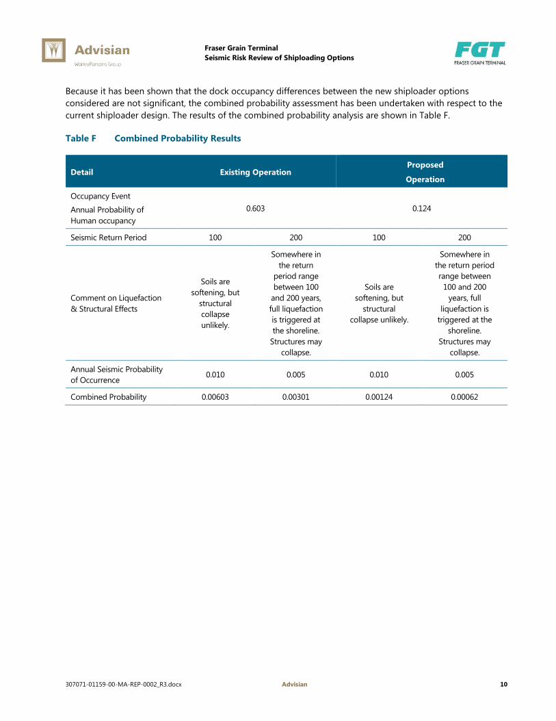
Because it has been shown that the dock occupancy differences between the new shiploader options considered are not significant, the combined probability assessment has been undertaken with respect to the current shiploader design. The results of the combined probability analysis are shown in Table F.
Table F Combined Probability Results
Detail Existing Operation Proposed
Operation
Occupancy Event
Annual Probability of Human occupancy
0.603 0.124
Seismic Return Period 100 200 100 200
Comment on Liquefaction & Structural Effects
Soils are softening, but
structural collapse unlikely.
Somewhere in the return
period range between 100
and 200 years, full liquefaction is triggered at the shoreline.
Structures may collapse.
Soils are softening, but
structural collapse unlikely.
Somewhere in the return period range between
100 and 200 years, full
liquefaction is triggered at the
shoreline. Structures may
collapse.
Annual Seismic Probability of Occurrence
0.010 0.005 0.010 0.005
Combined Probability 0.00603 0.00301 0.00124 0.00062

Fraser Grain Terminal Seismic Risk Review of Shiploading Options
307071-01159-00-MA-REP-0002_R3.docx Advisian 11
6 Summary of Findings The proposed FGT shiploading system provides a significant reduction in the number of hours during the year when the dock structure will be occupied by personnel. It is estimated that the percent of time that the dock will be occupied will decrease from 60.3% to 12.4% despite the fact that the proposed FGT operation will deliver a fourfold increase in exported material. In addition to the general reduction in the duration of occupancy, the average number of personnel on the dock structure during the (reduced) periods when the structure is occupied will also decrease significantly: from 8.6 persons to 3.7 persons, and it should be noted that no personnel will occupy the dock area or the equipment while shiploading is taking place. The preceding changes are based on the current shiploader design, but it can be seen in Table E that the differences amongst the shiploader alternatives assessed are not significant.
Major contributors to the reduction in human occupancy on the dock structure are the elimination of mobilization and demobilization time for the mobile shiploading equipment, currently necessary at every loading period, the absence of operational staff around the proposed shiploader, and significantly reduced requirements for clean-up of material spillage.
The occupancy changes estimated for the current shiploader design are summarized in Table G.
Table G Comparison of Existing and Future Operations Regarding Personnel Occupancy
Description Existing FSD Operation
Future FGT Operation - Based on Current
Design Improvement Comments
Probability that berth is occupied at any time 60.3% 12.4% 79% Reduction Significant Reduction
Average number of people on berth during periods of occupancy
(Weighted Average)
8.6 3.7 57% Reduction Significant Reduction
Total hours per year required for ship loading 3,810 1,955 49% Reduction Significant Reduction
Average number of people on berth structure during ship loading
10 0 Eliminated
Complete elimination of operations
personnel on the berth during shiploading
The combined probabilities of two events which, together, could present a risk to life safety were assessed and compared with respect to existing and future operations; i.e. the probability of a seismic event which could cause liquefaction and potential structural collapse combined with probability that there would be human occupancy on the dock structure. The results are shown on Table H.

Fraser Grain Terminal Seismic Risk Review of Shiploading Options
307071-01159-00-MA-REP-0002_R3.docx Advisian 12
Table H Summary of Combined Probability Results
Detail Existing Operation Proposed
Operation
Occupancy Event
Annual Probability of Human occupancy
0.603 0.124
Seismic Return Period 100 200 100 200
Comment on Liquefaction & Structural Effects
Soils are softening, but
structural collapse unlikely.
Somewhere in the return period range between
100 and 200 years, full
liquefaction is triggered at the
shoreline. Structures may
collapse.
Soils are softening,
but structural collapse unlikely.
Somewhere in the return period range
between 100 and 200 years, full liquefaction
is triggered at the shoreline. Structures
may collapse.
Combined Probability that the Dock is Occupied when the Seismic Event Occurs
0.00603 0.00301 0.00124 0.00062
The above analysis shows that there is a fourfold reduction in the risk that a seismic event which may cause collapse will occur when there is human occupancy of the dock. In addition, as a result of the proposed FGT operation, the average number of personnel on the dock structure during the (reduced risk) periods when the seismic event could occur when structure is occupied will also decrease significantly from 8.6 persons to 3.7 persons, and it should be noted that no personnel will occupy the dock area or the equipment while shiploading is taking place. This will result in a significant reduction in the risk to life safety of the grain terminal operation.
Table I shows a collated summary of the above data.

Fraser Grain Terminal Seismic Risk Review of Shiploading Options
307071-01159-00-MA-REP-0002_R3.docx Advisian 13
Table I Collated Summary
Description Existing FSD Operation
Future FGT Operation
Difference Comments
Annual throughput 1,000,000 t 3,177,600 218% increase Significant increase in material throughput.
Total hours per year where the berth structure is occupied by personnel
5,280 1,086 79% reduction Significant reduction in personnel occupancy.
Total hours per year where the berth structure is unoccupied
3,480 7,674 120% increase ---
Probability that berth is occupied at any time
60.3% 12.4% 79% reduction Significant reduction in the likelihood of personnel occupancy.
Probability that berth is unoccupied at any time
39.7% 87.6% 120% increase ---
Average number of people on berth during periods of occupancy (Weighted Average)
8.6 3.7 57% reduction Significant reduction in the number of personnel.
Total hours per year required for ship loading
3,810 1,955 49% reduction ---
Average number of people on berth structure during ship loading
10 0 Eliminated Complete elimination of personnel on the berth during shiploading.
Combined Probability that the Dock is Occupied when a 1 in 200 year Seismic Event Occurs
0.00301 0.00062 79% reduction Significant reduction in the likelihood of occupation.

Fraser Grain Terminal Seismic Risk Review of Shiploading Options
Appendix 1 Excerpt from 1419 Project Descrip V6.9

Project Description and Description of Operations CMC Ref. 1419
S-file: 1419 Project Descrip v6.9.docx Page 14 of 147 Printed: 2016 10 18 11:58
Figure 2.1-1 Product Flow Diagram
22 d/a 8 h/d 22 trains/a @ 5,000 t = 110,000 t/a39 d/a 20 h/d 39 trains/a @ 11,200 t = 436,800 t/a61 d/a 61 trains/a = 546,800 t/a 410,100 t/a
410,100 t/a820 h/a at 500 t/h
136,700 t/a 136,700 t/a
370 d/a 219 h/a at 625 t/h
370 trains/a4,007,600 t/a 111 d/a at 24 h/j TOTALS 39,670 t 80.1 units/a 3,177,600 t/a
309 d/a 7 h/d 309 trains/a @ 11,200 t = 3,460,800 t/a
309 d/a 309 trains/a = 3,460,800 t/a3,460,800 t/a 2,630,800 t/a
1,619 h/a at 1,625 t/h
4,007,600 t/a
600,000 t/a 24,000 TEU/a @ 25 t ≈ 600,000 t/a253 d/a at 10 h/d
200,000 t/a 2,222 units/a @ 90 t ≈ 200,000 t/a253 d/a at 10 h/d
30,000 t/a 667 units/a @ 45 t ≈ 30,000 t/a253 d/a at 10 h/d
Flat storage facility for
18,000 t
STORAGE
Steel silos for
77,000 t
HANDY
HANDYMAX
FIGURES TAKEN DIRECTLY FROM THERAIL SERVICE SYSTEM
DOCUMENT
BULK TRUCKS
2,000 t/h
EXISTING JV SHED 1 FACILITIES
NEW FRASER GRAIN TERMINAL FACILITIES
NEW SHIPPING FACILITIES(PARTIALLY ON THE EXISTING FSD
WHARF)
CONTAINERS
RAILCARS
LEGEND
RECEIVING PIT
RECEIVING PIT
Maximum unloading rate of
1,000 t/h
Maximum unloading rate of
OCEAN GOING VESSELS
PANAMAX
AVERAGE CAPACITY
NUMBER OF VESSELS
THROUGHPUT
20.0 units/a
40.1 units/a
50,531 t
VESSEL TYPE
STORAGE
25,040 t 20.0 units/a
41,551 t
1,010,625 t/a
1,666,176 t/a
500,799 t/a
INBOUND TRAFFIC (ALL BY RAIL) RECEIVING STORAGE SHIPPING FACILITIES OUTBOUND TRAFFIC (MIXED MODES)
Project Description and Description of Operations CMC Ref. 1419
S-file: 1419 Project Descrip v6.9.docx Page 86 of 147 Printed: 2016 10 18 11:58
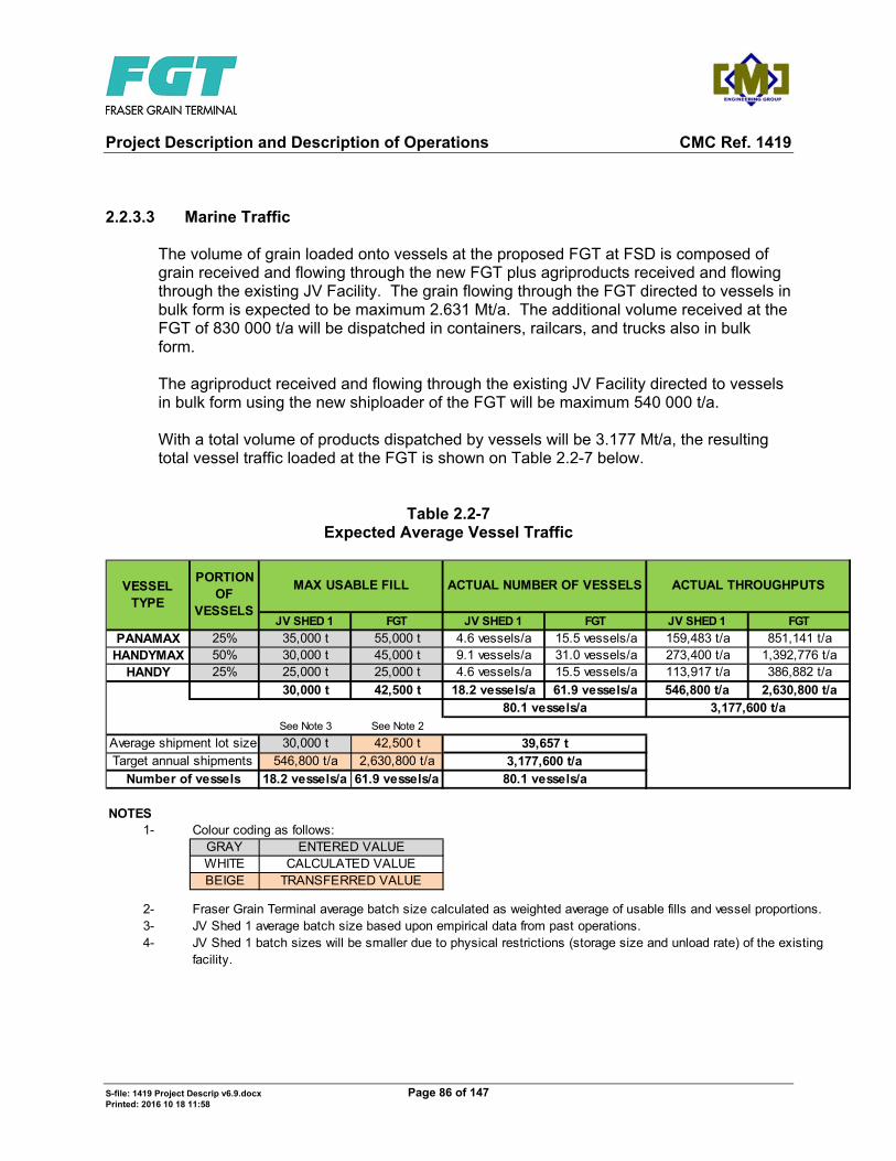
2.2.3.3 Marine Traffic
The volume of grain loaded onto vessels at the proposed FGT at FSD is composed of grain received and flowing through the new FGT plus agriproducts received and flowing through the existing JV Facility. The grain flowing through the FGT directed to vessels in bulk form is expected to be maximum 2.631 Mt/a. The additional volume received at the FGT of 830 000 t/a will be dispatched in containers, railcars, and trucks also in bulk form. The agriproduct received and flowing through the existing JV Facility directed to vessels in bulk form using the new shiploader of the FGT will be maximum 540 000 t/a. With a total volume of products dispatched by vessels will be 3.177 Mt/a, the resulting total vessel traffic loaded at the FGT is shown on Table 2.2-7 below.
Table 2.2-7 Expected Average Vessel Traffic
JV SHED 1 FGT JV SHED 1 FGT JV SHED 1 FGT
PANAMAX 25% 35,000 t 55,000 t 4.6 vessels/a 15.5 vessels/a 159,483 t/a 851,141 t/aHANDYMAX 50% 30,000 t 45,000 t 9.1 vessels/a 31.0 vessels/a 273,400 t/a 1,392,776 t/a
HANDY 25% 25,000 t 25,000 t 4.6 vessels/a 15.5 vessels/a 113,917 t/a 386,882 t/a
30,000 t 42,500 t 18.2 vessels/a 61.9 vessels/a 546,800 t/a 2,630,800 t/a
See Note 3 See Note 2
30,000 t 42,500 t546,800 t/a 2,630,800 t/a
18.2 vessels/a 61.9 vessels/a
NOTES1- Colour coding as follows:
GRAYWHITEBEIGE
2-3-4-
3,177,600 t/a
Average shipment lot sizeTarget annual shipments
Number of vessels
39,657 t
Fraser Grain Terminal average batch size calculated as weighted average of usable fills and vessel proportions.JV Shed 1 average batch size based upon empirical data from past operations.JV Shed 1 batch sizes will be smaller due to physical restrictions (storage size and unload rate) of the existing facility.
CALCULATED VALUETRANSFERRED VALUE
ENTERED VALUE
VESSEL TYPE
ACTUAL NUMBER OF VESSELS
80.1 vessels/a
3,177,600 t/a
ACTUAL THROUGHPUTSPORTION
OF VESSELS
MAX USABLE FILL
80.1 vessels/a

VFPA Project and Environmental Review – Marine Structures Supplemental Information
4321 Still Creek Drive Burnaby BC V5C 6S7 Canada
307071-01159-00-MA-REP-0003
www.advisian.com


Fraser Grain Terminal VFPA Project and Environmental Review – Marine Structures Supplemental Information
307071-01159-00-MA-REP-0003_R0.docx Advisian iii
Table of Contents 1 Project Description ...................................................................................................................................................................... 1
2 Reuse of Existing FSD Structures and Services ................................................................................................................. 2
2.1 Fenders ............................................................................................................................................................................ 2
2.2 Bollards ............................................................................................................................................................................ 2
2.3 Concrete Pile and Deck Structure ......................................................................................................................... 2
2.4 Services............................................................................................................................................................................ 3
3 Supplementary Structures ........................................................................................................................................................ 4
3.1 Water Side Rail Foundations .................................................................................................................................. 4
3.2 Land Side Rail, Shuttle Conveyor, and Shiploader Tower Foundations ................................................. 5
3.3 Gangway Landing Platform ..................................................................................................................................... 5
4 Seismic Design .............................................................................................................................................................................. 6
5 Closing .............................................................................................................................................................................................. 7

Fraser Grain Terminal VFPA Project and Environmental Review – Marine Structures Supplemental Information
307071-01159-00-MA-REP-0003_R0.docx Advisian 1
1 Project Description Fraser Grain Terminal (FGT) Limited is proposing to develop a grain export terminal at Fraser Surrey Docks (FSD) Berth No. 3/4, on the Fraser River. FSD Berth No. 3/4 is already used for the export of agricultural products such as canola, malt and lentils; mobile equipment on rubber tires is currently used to load the vessels. In contrast, the FGT is proposing to use a more automated, remote controlled and efficient rail mounted shiploader.
The FGT operation will reuse much of the existing FSD Berth No. 3/4 infrastructure including the existing concrete pile and deck, the fender system and the bollards. Supplementary structural support for the vertical loads from the new water side shiploader rail, consisting of steel pipe piles and steel beams, will be provided. New foundations will be provided for the land side shiploader rail, the shuttle conveyor and the shiploader (transfer) tower. These foundations will consist of steel pipe piles with cast in place concrete pile caps. Lateral loads from the new shiploader will be taken through the existing pile and deck structure and the new foundations. Existing FSD services will be reused but portions of some services will require relocation to facilitate the installation of the supplemental structural supports. Seismic design will include resisting inertia loads from the new shiploader through the existing deck and the supplemental structural supports; however, as described in Section 4, ground improvements to prevent liquefaction are not included in the proposed works.
This report is provided at the request of FGT to supplement the Vancouver Fraser Port Authority (VFPA) Project and Environmental Review (PER) application. This memorandum, which describes the project with particular emphasis on the in-water portion of the work, should be read in conjunction with the other Advisian documents submitted for PER for the project’s marine structures. These documents include the PER drawings Nos. 307071-01159-00-MA-DSK-1500 to 1506 and the Advisian report entitled: “Seismic Risk Review of Shiploading Options” (Report No. 307071-01159-00-MA-REP-0002).

Fraser Grain Terminal VFPA Project and Environmental Review – Marine Structures Supplemental Information
307071-01159-00-MA-REP-0003_R0.docx Advisian 2
2 Reuse of Existing FSD Structures and Services
2.1 Fenders
The existing Berth No. 3/4 fenders will continue to be used in the FGT operation.
The existing fenders are Sumitomo Lambda 600H x 1500L CL2 rubber spaced at 7.6 m (25 ft.) centres. Berthing analysis was completed based on the maximum design vessel berthing in ballast (maximum berthing displacement of 36,000 tonnes) at a berthing velocity of 0.10 m/s. The maximum design vessel is a Panamax vessel with an overall length limited to 225 m and with draft limited to a maximum of 11.5 m (partial load). The analysis found that the existing fender units are satisfactory for the berthing of ballasted maximum design vessel.
2.2 Bollards
The existing bollards at Berth No. 3/4 are typically of the following casting types:
Elliot Steel A-19 bollard casting secured to the concrete deck with 6 anchor bolts, or
Liverpool 555# cleat casting secured to the concrete deck with 4 or 5 anchor bolts.
In addition, there is a “one off” single bitt bollard casting at Bent 23.
FSD has indicated that the safe working load (SWL) of these bollards (excluding the single bitt bollard at Bent 23, for which the SWL is unknown) is 60 tonnes or 80 tonnes depending on the location. Refer to Advisian drawing 307071-01159-00-MA-DSK-1503 for the bollard ratings and locations.
A simplified mooring analysis was undertaken for the maximum design vessel moored under various conditions of wind and current. The “one off” single bitt bollard casting at Bent 23 was not included in the analysis. Design criteria for wind and current are shown on Advisian drawing No. 307071-01159-00-MA-DSK-1501.
The analysis found that the existing 60 and 80 tonne bollards are considered satisfactory for the mooring of the design vessels based on the existing bollard SWLs provided by FSD. It is noted that some of the existing bollards were an upgrade following the original construction of the concrete dock. At this time, the design drawings for the bollard upgrade installation have not been located. During detailed design, further efforts will be made to locate these bollard installation drawings so that an independent verification of the current SWL ratings of the existing bollards may be completed.
2.3 Concrete Pile and Deck Structure
The existing Berth No. 3/4 structure, constructed in 1968/1969, consists of the following elements:
Precast pre-stressed 610 mm (24 inch) octagonal concrete piles, both vertical and battered.
Cast in place concrete pile caps at 7.62 m (25 ft.) centres running perpendicular to the berth face.
Fraser Grain Terminal VFPA Project and Environmental Review – Marine Structures Supplemental Information
307071-01159-00-MA-REP-0003_R0.docx Advisian 3
Pre-stressed and post-tensioned (PT) solid concrete haunched deck slabs; slabs are 1.83 m wide and 385 mm thick at midspan and 610 mm thick at the ends. There are two PT ducts per slab and the layout of the ducts changes at Bent 8 located near the east end of Berth No. 3/4 structure.
Deck overlay (610 mm thick) supported on the concrete deck slabs; the overlay is consists of 75 mm of asphalt, over a 150 mm base course, over 385 mm of crushed rock.
The existing Berth No. 3/4 concrete pile and deck will remain in place. As described in Section 3, it will be necessary to core though portions of the existing deck to facilitate the installation of the new piles that will be installed to support the water side rail for the new shiploader. It will be necessary to reduce the allowable load on this portion of the existing FSD deck to 14.4 kPa (300 psf) from its current allowable load rating of 28.7 kPa (600 psf) as a result of deck coring (see Advisian drawing 307071-01159-00-MA-DSK-1501 and 1504).
2.4 Services
Existing services in the Berth No. 3/4 area include:
Storm sewer
Underground electrical
Underground fibre optics
Gas line
Sanitary sewer
Water main
These existing services, which are shown on Advisian drawing 307071-01159-00-MA-DSK-1502, will be reused in the FGT operation. However, portions of some of the services may need to be relocated or exposed and protected to facilitate construction as shown on Advisian drawing 307071-01159-00-MA-DSK-1503 and as described below:
Portions of existing electrical and water lines may need to be relocated to pass under the concrete beam which will be installed to support the shiploader landside rail or to pass around the shuttle conveyor foundations.
Based on the services reference drawing supplied by FSD, there are service lines (water, fibre optic and 2 electrical) which currently run across the dock within the deck overlay midway between Bent 20 and 21, where the new piles to support the water side rail will be installed. Accordingly, these lines may also need to be re-routed; however, it is recognized that location accuracy of services drawings will require further verification in detailed design which may demonstrate that the re-routing currently shown on the drawings is not actually necessary.
The existing electrical and fibre optic cables running under the deck overlay adjacent to the berth face will be exposed and protected as required during the installation of the new piles installed to support the water side shiploader rail.

Fraser Grain Terminal VFPA Project and Environmental Review – Marine Structures Supplemental Information
307071-01159-00-MA-REP-0003_R0.docx Advisian 4
3 Supplementary Structures
3.1 Water Side Rail Foundations
New steel pipe piles (610 mm diameter); will be installed through the existing Berth No. 3/4 deck structure to support the ship loader waterside side rail. There are two different configurations for the pile installation to accommodate the change in the PT duct configuration at Bent 8. Piles are located so that existing PT stands will remain unchanged as a result of the new construction. A total of 69 piles will be required.
The expected work plan for the construction of the water side rail foundations is shown below:
The contractor will begin by saw-cutting the deck asphalt at each pile location, followed by removal of the asphalt and gravel ballast below. This will be followed by the provision of the protection/ relocation of any services which have been exposed and a survey to confirm rebar/strand layout. The next step will be coring/saw-cutting through the haunched slabs to create the openings required for pile driving. Exposed strand and re-bar at the cut face will be burned back from the exposed surface, followed by cleaning and patching with a dry pack grout.
The contractor will install temporary guides at the deck surface to facilitate pile positioning and provide protection against damage to the pile coating.
During the preparation for the openings described above, the contractor will prepare the seabed for pile driving. The slope protection below the existing deck structure generally comprises a combination of coarse rock and containment wire mesh. The rock is too coarse to drive piles through without significant risk of damage to the piles. Therefore, the contractor will use divers to mark the limits of the areas to be cleared, using the existing piles and main bulkhead wall for reference, and cut the wire mesh. The mesh will be folded back, up the slope toward the main bulkhead wall and secured. A barge mounted long-reach excavator will be used, generally at medium to low tides, to remove the coarse rock on the slope. The excavator may use a conventional bucket with thumb or a small hydraulic clamshell. Rock will be temporarily stored on a barge until reinstalled. Divers will inspect the seabed immediately before pile driving to confirm that no rocks have fallen into the pile window.
Once the seabed has been prepared, a crane with pile driving equipment will install piles through the deck. The pile driving rig, may be floating, or could be land-based equipment working from on the deck. The contractor may start pile installation with a vibratory (vibro) hammer, but will be required to finish driving with a diesel or similar impact hammer to prove the capacity for each pile.
Following installation of the piles, the barge mounted excavator will reinstate the rock slope protection, using the assistance of divers to confirm correct installation. Galvanized corrugated or HDPE sleeves may be installed around each pile to protect the pile coating from damage during reinstatement of the rock. Once the rock is confirmed to be installed correctly, the divers will reinstate the wire mesh, trimming to suit the new piles, and adding lap splices to strengthen the cut joints.
Pre- and post-installation surveys will determine if any rock was spilled over the edge of the offshore containment sheet pile wall, in which case that accumulated material will be removed. Pre- and post-installation surveys will also be used to confirm final grade of the slope protection.

Fraser Grain Terminal VFPA Project and Environmental Review – Marine Structures Supplemental Information
307071-01159-00-MA-REP-0003_R0.docx Advisian 5
It is understood that full access will be given to the contractor completing the installation of in-water works. On this basis, it is expected that the total duration for in-water works associated with water side rail is 2 to 3 months. This assumes generally continuous work flow from one end to the other and does not include the superstructure installation (i.e., the rail and support beams).
The relevant areas for environmental considerations related to the in-water works are provided below:
The total plan area (plan footprint) of seabed that will be disturbed to allow the piles for the water side rail to be installed is estimated to be 700 square metres.
The total plan area (plan footprint) of the 69 piles for the water side rail is 20 square metres.
3.2 Land Side Rail, Shuttle Conveyor, and Shiploader Tower Foundations
New steel pipe piles will be installed behind the existing Berth No. 3/4 dock structure to support the ship loader land side rail (914 mm diameter), the shuttle conveyor (914 mm and 1219 mm diameter) and the shiploader (transfer) tower (1219 mm diameter). All of these piles involve land based construction only and will be fully embedded into the existing upland portion of the site. Cast in place concrete beams will be installed over the piles to support the shiploader land side rail or the ship loading structures as required.
For the installation of the piles described above, localized excavation will be undertaken to expose the existing tie rods (which support the sheet pile retaining wall located at the back of the existing Berth No. 3/4 dock structure) to prevent conflict or damage during construction. As for the piles under the water side rail, the contractor may start pile installation with a vibro hammer, but will be required to finish driving with a diesel or similar impact hammer to prove the capacity for each pile.
3.3 Gangway Landing Platform
The new water side rail and its supports will be located on a portion of the existing FSD deck adjacent to the berth face that is currently used to land the vessel gangway that must be in place when the ship is at the berth to provide vessel access/egress. After installation of the new water side rail, there will be inadequate clear deck space remaining between the existing concrete bull rail and the new supports for the water side rail for safely landing the shore end of a vessel gangway.
For this reason, as shown on Advisian drawing No. 307071-01159-00-MA-DSK-1503, 1504, and 1505, a new steel gangway landing platform will be installed above the existing concrete bull rail. This gangway landing platform will provide a 2 m wide level surface; the platform location shown will serve typical stern gangways. As indicated by Note 3 on DSK-1504, the need for one or more additional gangway landing platforms to accommodate mid-ship gangways will be assessed during detailed design and additional platforms will be provided if required.

Fraser Grain Terminal VFPA Project and Environmental Review – Marine Structures Supplemental Information
307071-01159-00-MA-REP-0003_R0.docx Advisian 6
4 Seismic Design The VFPA has advised FGT that the design of the marine structures shall meet the intent of ASCE 61-14 (Seismic Design of Pile-Supported Piers and Wharves). Within the ASCE 61-14 standard, FGT has advised Advisian that the VFPA has specified that the marine structures fall under the ‘Low Design Classification’, meaning that the only required seismic performance criteria is the provision of life safety protection in the Design Earthquake. Hence FGT is proposing an unmanned ship loader to replace the movable equipment currently being used at the site. FGT has retained Advisian to review the statistical probability of a seismic event occurring which could lead to collapse of the existing and proposed marine structures with the potential for loss of life. The results of the review are presented in the separate Advisian report entitled: “Seismic Risk Review of Shiploading Options” (Report No. 307071-01159-00-MA-REP-0002) which is included in the supporting documentation provided to the VFPA for the FGT PER permit application.
The proposed FGT facilities will operate at significantly reduced personnel occupancy on the marine structures and the shiploader as compared to current operations. It is understood that the VFPA will consider the following in its determination of the seismic design requirements to be applied to the project:
The overall reduction in personnel occupancy resulting from the use of the proposed new low occupancy shiploader design; and,
The results of the analysis of the combined probability of the occurrence of various seismic events with the occurrence of personnel occupancy of the dock and shiploader under both the existing and proposed operations.
At the instruction of FGT and pending the determination of VFPA regarding its seismic design requirements for the project as outlined above, the proposed works do not include the provision of ground improvement to prevent liquefaction and the proposed works are not designed to accommodate the loss of soil strength and forces associated with soil flows resulting from liquefaction, should it occur.
The new marine structures will be designed to withstand the inertia forces associated with ASCE 61-14 Design Earthquake for a wharf of low design classification without consideration of the effects of liquefaction.
The existing FSD Berth No. 3/4 marine structures will not be modified or upgraded to comply with ASCE 61-14 seismic provisions.

Fraser Grain Terminal VFPA Project and Environmental Review – Marine Structures Supplemental Information
307071-01159-00-MA-REP-0003_R0.docx Advisian 7
5 Closing This report has been prepared to supplement the other Advisian documents provided to the VFPA in support of the FGT PER application. It provides a summary of the marine structural requirements for the project and also gives additional information about the assessments undertaken regarding the re-use of existing FSD structures and services and about possible construction methodologies.