examples of automation x-sel serial communication of automation x-sel serial communication z...
TRANSCRIPT
Examples of Automation
X-SEL Serial Communication
Examples of Automation – Table of Contents
Overview of Networks DeviceNet Confectionery Sizer/Sorter .....................5
1. Explanation of Application..................................................................................................5
(1) System configuration................................................................................................................................5 (2) Explanation of operation...........................................................................................................................6
2. Communication Settings ....................................................................................................6 (1) Connect the devices.................................................................................................................................7 (2) Set the X-SEL controller...........................................................................................................................8 (3) Set the master unit ................................................................................................................................ 10 (4) Perform a line test ................................................................................................................................. 10 (5) Assign I/Os ............................................................................................................................................ 11 (6) Start the system .................................................................................................................................... 15
3. Sample Program ..............................................................................................................15 (1) X-SEL controller sample program ......................................................................................................... 15 (2) PLC sample program ............................................................................................................................ 16
CC-Link Board Solderer for Cell Production Line ...17
1. Explanation of Application................................................................................................17 (1) System configuration............................................................................................................................. 17 (2) Explanation of operation........................................................................................................................ 18
2. Communication Settings ..................................................................................................18 (1) Connect the devices................................................................................ Error! Bookmark not defined. (2) Set the X-SEL controller.......................................................................... Error! Bookmark not defined. (3) Set the master unit .................................................................................. Error! Bookmark not defined. (4) Perform a line test ................................................................................... Error! Bookmark not defined. (5) Start the system ...................................................................................... Error! Bookmark not defined.
3. Sample Program ................................................................ Error! Bookmark not defined. (1) PLC sample program .............................................................................. Error! Bookmark not defined.
Ethernet Work Sorter/Pick-up.. Error! Bookmark not defined.
1. Explanation of Application..................................................Error! Bookmark not defined. (1) System configuration............................................................................... Error! Bookmark not defined. (2) Explanation of operation.......................................................................... Error! Bookmark not defined.
2. Communication Settings .................................................... Error! Bookmark not defined. (1) Connect the devices................................................................................ Error! Bookmark not defined. (2) Set the X-SEL controller.......................................................................... Error! Bookmark not defined. (3) Setting the camera .................................................................................. Error! Bookmark not defined. (4) Perform a line test ................................................................................... Error! Bookmark not defined. (5) Start the system ...................................................................................... Error! Bookmark not defined.
3. Sample Program ................................................................ Error! Bookmark not defined. (1) X-SEL controller program........................................................................ Error! Bookmark not defined.
Protocol Communication (RS232C) Wood Length Specifier/Cutter .........Error! Bookmark not defined.
1. Explanation of Application..................................................Error! Bookmark not defined. (1) System configuration............................................................................... Error! Bookmark not defined. (2) Explanation of operation.......................................................................... Error! Bookmark not defined.
2. Communication Settings .................................................... Error! Bookmark not defined. (1) Set the X-SEL controller.......................................................................... Error! Bookmark not defined. (2) Setting the touch panel............................................................................ Error! Bookmark not defined. (3) Connect the devices................................................................................ Error! Bookmark not defined. (4) Start the system ...................................................................................... Error! Bookmark not defined.
Free Protocol Communication (RS232C) PC Board Checker.... Error! Bookmark not defined.
1. Explanation of Application..................................................Error! Bookmark not defined. (1) System configuration............................................................................... Error! Bookmark not defined. (2) Explanation of operation.......................................................................... Error! Bookmark not defined.
2. Communication Settings .................................................... Error! Bookmark not defined. (1) Connect the devices................................................................................ Error! Bookmark not defined. (2) Set the X-SEL controller.......................................................................... Error! Bookmark not defined. (3) Setting the PC ......................................................................................... Error! Bookmark not defined. (4) Perform a line test ................................................................................... Error! Bookmark not defined. (5) Start the system ...................................................................................... Error! Bookmark not defined.
3. Sample Program ................................................................ Error! Bookmark not defined. (1) Test program using HyperTerminal......................................................... Error! Bookmark not defined.
Table of Contents

Overview of Networks
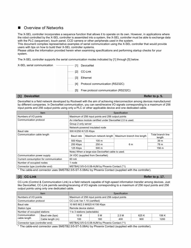
The X-SEL controller incorporates a sequence function that allows it to operate on its own. However, in applications where the robot controlled by the X-SEL controller is assembled into a system, the X-SEL controller must be able to exchange data with the PLC (sequencer), touch panel, CCD camera or other peripherals used in the system. This document compiles representative examples of serial communication using the X-SEL controller that would provide users with tips on how to build their X-SEL controller systems. Please utilize the information provided herein when examining specifications and performing startup checks for your system. The X-SEL controller supports the serial communication modes indicated by [1] through [5] below. X-SEL serial communication [1] DeviceNet Refer to p. 5.
DeviceNet is a field network developed by Rockwell with the aim of achieving interconnection among devices manufactured by different companies. In DeviceNet communication, you can send/receive I/O signals corresponding to a maximum of 256 input points and 256 output points using only a PLC or other applicable device and one dedicated cable.
Item Specification Numbers of I/O points Maximum of 256 input points and 256 output points
An interface module certified under DeviceNet 2.0 is used. Group 2 only server
Communication protocol
Network-powered insulated node Baud rate 500 K/250 K/125 Kbps
Baud rate Maximum network length Maximum branch line length Total branch line length
Communication cable length
500 Kbps 100 m 39 m 250 Kbps 250 m 6 m 78 m
125 Kbps 500 m 156 m Note) When a large-size DeviceNet cable is used.
Communication power supply 24 VDC (supplied from DeviceNet) Current consumption for communication 60 mA Number of occupied nodes 1 node Connector type (controller end) MSTBA2.5/5-G-5.08-AUM by Phoenix Contact (*1) * The cable-end connector uses SMSTB2.5/5-ST-5.08AU by Phoenix Contact (supplied with the controller). [2] CC-Link Refer to p. 17.
CC-Link (Control & Communication Link) is a field network capable of high-speed information transfer among devices. Just like DeviceNet, CC-Link permits sending/receiving of I/O signals corresponding to a maximum of 256 input points and 256 output points using only one dedicated cable.
Item Specification Numbers of I/O points Maximum of 256 input points and 256 output points Communication protocol CC-Link Ver.1.10 (certified) Baud rate 10 M/5 M/2.5 M/625 K/156 Kbps Station type Remote device station Number of occupied stations 1 to 3 stations (selectable)
Baud rate (bps) 10 M 5 M 2.5 M 625 K 156 K Communication cable length Cable length (m) 100 160 400 900 1200 Connector type (controller end) MSTBA2.5/5-G-5.08-AUM by Phoenix Contact (*1) * The cable-end connector uses SMSTB2.5/5-ST-5.08AU by Phoenix Contact (supplied with the controller).
[1] DeviceNet [2] CC-Link [3] Ethernet [4] Protocol communication (RS232C) [5] Free protocol communication (RS232C)
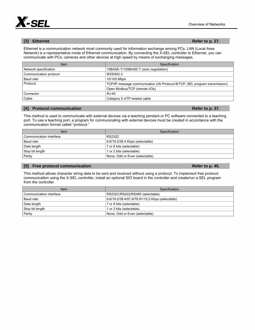
[3] Ethernet Refer to p. 27.
Ethernet is a communication network most commonly used for information exchange among PCs. LAN (Local Area Network) is a representative mode of Ethernet communication. By connecting the X-SEL controller to Ethernet, you can communicate with PCs, cameras and other devices at high speed by means of exchanging messages.
Item Specification Network specification 10BASE-T/100BASE-T (auto negotiation) Communication protocol IEEE802.3 Baud rate 10/100 Mbps
TCP/IP message communication (IAI Protocol B/TCP, SEL program transmission) Protocol Open Modbus/TCP (remote I/Os)
Connector RJ-45 Cable Category 5 UTP twisted cable [4] Protocol communication Refer to p. 37.
This method is used to communicate with external devices via a teaching pendant or PC software connected to a teaching port. To use a teaching port, a program for communicating with external devices must be created in accordance with the communication format called “protocol.”
Item Specification Communication interface RS232C Baud rate 9.6/19.2/38.4 Kbps (selectable) Data length 7 or 8 bits (selectable) Stop bit length 1 or 2 bits (selectable) Parity None, Odd or Even (selectable) [5] Free protocol communication Refer to p. 45.
This method allows character string data to be sent and received without using a protocol. To implement free protocol communication using the X-SEL controller, install an optional SIO board in the controller and create/run a SEL program from the controller.
Item Specification Communication interface RS232C/RS422/RS485 (selectable) Baud rate 9.6/19.2/38.4/57.6/76.8/115.2 Kbps (selectable) Data length 7 or 8 bits (selectable) Stop bit length 1 or 2 bits (selectable) Parity None, Odd or Even (selectable)
Overview of Networks
DeviceNet Confectionery Sizer/Sorter
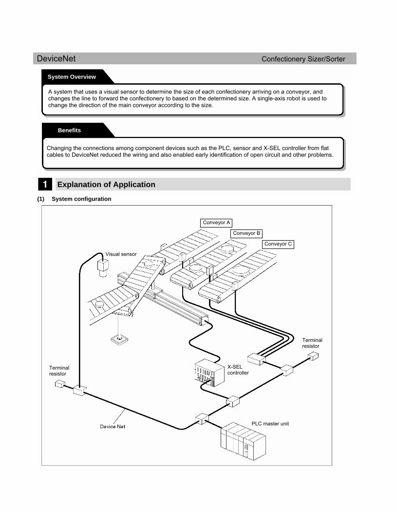
Explanation of Application (1) System configuration
System Overview
A system that uses a visual sensor to determine the size of each confectionery arriving on a conveyor, and changes the line to forward the confectionery to based on the determined size. A single-axis robot is used to change the direction of the main conveyor according to the size.
Benefits
Changing the connections among component devices such as the PLC, sensor and X-SEL controller from flat cables to DeviceNet reduced the wiring and also enabled early identification of open circuit and other problems.
Conveyor A
Conveyor B
Conveyor C
Visual sensor
Terminal resistor
X-SEL controller
Terminal resistor
PLC master unit
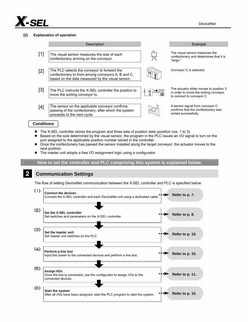
(2) Explanation of operation
Description Example
[1] The visual sensor measures the size of each confectionery arriving on the conveyor.
The visual sensor measures the confectionery and determines that it is “large.”
[2] The PLC selects the conveyor to forward the confectionery to from among conveyors A, B and C, based on the data measured by the visual sensor.
Conveyor C is selected.
[3] The PLC instructs the X-SEL controller the position to move the sorting conveyor to.
The actuator slider moves to position 3 in order to move the sorting conveyor to connect to conveyor C.
[4] The sensor on the applicable conveyor confirms passing of the confectionery, after which the system proceeds to the next cycle.
A sensor signal from conveyor C confirms that the confectionery was sorted successfully.
The X-SEL controller stores the program and three sets of position data (position nos. 1 to 3). Based on the size determined by the visual sensor, the program in the PLC issues an I/O signal to turn on the
port assigned to the applicable position number stored in the controller. Once the confectionery has passed the sensor installed along the target conveyor, the actuator moves to the
next position. The master unit adopts a free I/O assignment logic using a configurator.
How to set the controller and PLC comprising this system is explained below.
Communication Settings
The flow of setting DeviceNet communication between the X-SEL controller and PLC is specified below.
Conditions
DeviceNet
Connect the devices Connect the X-SEL controller and each DeviceNet unit using a dedicated cable. Set the X-SEL controller Set switches and parameters on the X-SEL controller. Set the master unit Set master unit switches on the PLC. Perform a line test Input the power to the connected devices and perform a line test. Assign I/Os Once the line is connected, use the configurator to assign I/Os to the connected devices. Start the system After all I/Os have been assigned, start the PLC program to start the system.
Refer to p. 7. Refer to p. 8. Refer to p. 10. Refer to p. 10. Refer to p. 11.
Refer to p. 15.

Each device connected to DeviceNet, other than the master unit, is called “slave unit.” Up to 63 slave units can be connected simultaneously. (Including the master unit, a maximum of 64 devices can be connected to the network.) To implement communication between each slave unit and the master unit, the following settings are required:
(1) Set the node addresses and baud rate Refer to p. 8 to 10. (2) Create a scan list (to cause the master unit to recognize each slave unit) → Refer to the operation manual for the applicable master unit. (3) Assign I/Os (I/O signals) for each slave unit (to the master unit) Refer to p. 11 to 14.
Slave units can be assigned by “fixed assignment” or “free assignment.” • Fixed assignment --- The assigned areas are fixed, and node addresses are assigned sequentially from 0. This method
is suitable for small networks connecting a limited number of devices. • Free assignment --- Configurator software is used to assign slaves in a desired manner. All connected devices can be
monitored, which is ideal for networks connecting many devices. With both fixed assignment and free assignment, one channel consists of two bytes, and a slave having 16 I/O points occupies one channel. A slave having more than 16 I/O points occupies multiple channels. The X-SEL controller lets you freely set one to 16 occupied channels, with each channel consisting of 16 I/O points (i.e., there will be 16 input points and 16 output points if there is only one channel, or 256 input points and 256 output points when there are 16 channels). In this example, free assignment using a configurator is explained based on the settings specified below.
Node address Unit type Connected unit Numbers of I/O points
Number of occupied channels
0 Master unit Omron CJ series - -
1 Slave unit X-SEL controller 32 input points 16 output points
2 input channels 1 output channel
2 Slave unit Sensor terminal 16 input points 1 channel 3 Intelligent slave unit Visual sensor controller 8 bytes 4 channels
The setting procedure based on the above specifications is explained step by step. (1) Connect the devices
Connect the dedicated DeviceNet cable to the X-SEL controller as shown below.
(Black)
(Blue)
(Bare)
(White)
(Red)
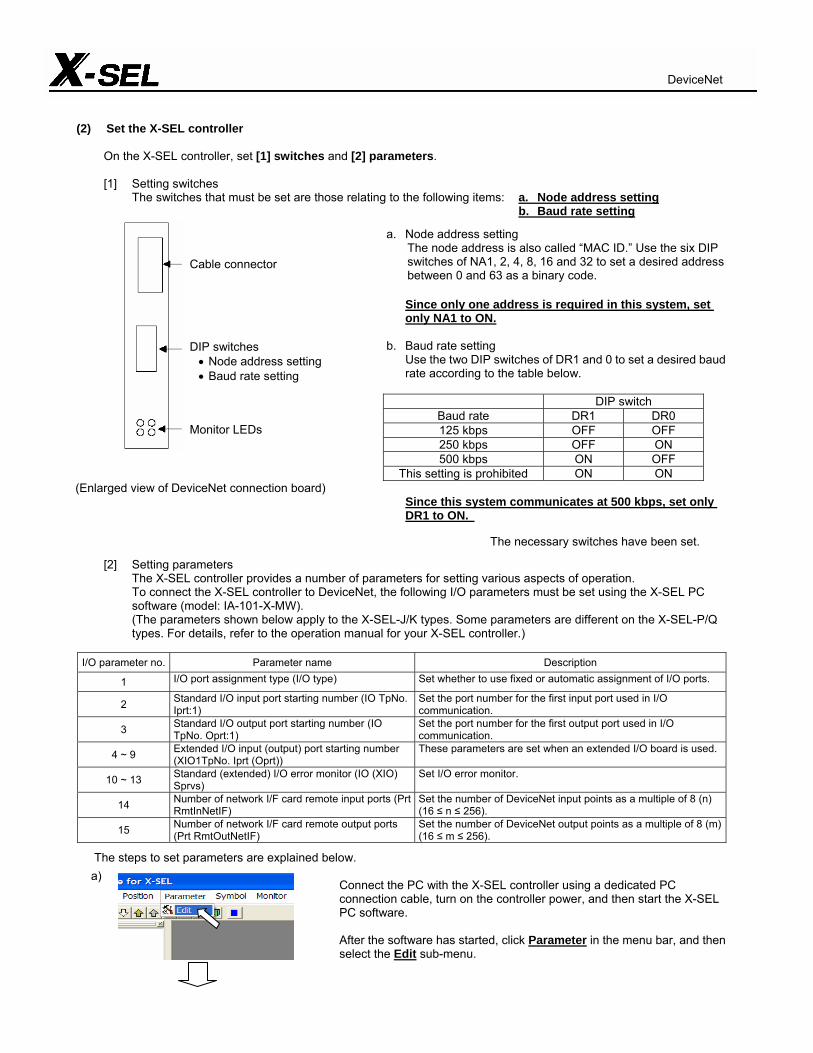
(2) Set the X-SEL controller
On the X-SEL controller, set [1] switches and [2] parameters.
[1] Setting switches The switches that must be set are those relating to the following items: a. Node address setting b. Baud rate setting
a. Node address setting The node address is also called “MAC ID.” Use the six DIP
switches of NA1, 2, 4, 8, 16 and 32 to set a desired address between 0 and 63 as a binary code.
Since only one address is required in this system, set
only NA1 to ON. b. Baud rate setting Use the two DIP switches of DR1 and 0 to set a desired baud
rate according to the table below.
DIP switch Baud rate DR1 DR0 125 kbps OFF OFF 250 kbps OFF ON 500 kbps ON OFF
This setting is prohibited ON ON (Enlarged view of DeviceNet connection board)
Since this system communicates at 500 kbps, set only DR1 to ON.
The necessary switches have been set.
[2] Setting parameters The X-SEL controller provides a number of parameters for setting various aspects of operation. To connect the X-SEL controller to DeviceNet, the following I/O parameters must be set using the X-SEL PC
software (model: IA-101-X-MW). (The parameters shown below apply to the X-SEL-J/K types. Some parameters are different on the X-SEL-P/Q
types. For details, refer to the operation manual for your X-SEL controller.)
I/O parameter no. Parameter name Description
1 I/O port assignment type (I/O type) Set whether to use fixed or automatic assignment of I/O ports.
2 Standard I/O input port starting number (IO TpNo. Iprt:1)
Set the port number for the first input port used in I/O communication.
3 Standard I/O output port starting number (IO TpNo. Oprt:1)
Set the port number for the first output port used in I/O communication.
4 ~ 9 Extended I/O input (output) port starting number (XIO1TpNo. Iprt (Oprt))
These parameters are set when an extended I/O board is used.
10 ~ 13 Standard (extended) I/O error monitor (IO (XIO) Sprvs)
Set I/O error monitor.
14 Number of network I/F card remote input ports (Prt RmtInNetIF)
Set the number of DeviceNet input points as a multiple of 8 (n) (16 ≤ n ≤ 256).
15 Number of network I/F card remote output ports (Prt RmtOutNetIF)
Set the number of DeviceNet output points as a multiple of 8 (m) (16 ≤ m ≤ 256).
The steps to set parameters are explained below.
Connect the PC with the X-SEL controller using a dedicated PC connection cable, turn on the controller power, and then start the X-SEL PC software. After the software has started, click Parameter in the menu bar, and then select the Edit sub-menu.
Cable connector DIP switches • Node address setting • Baud rate setting
Monitor LEDs
a)
DeviceNet
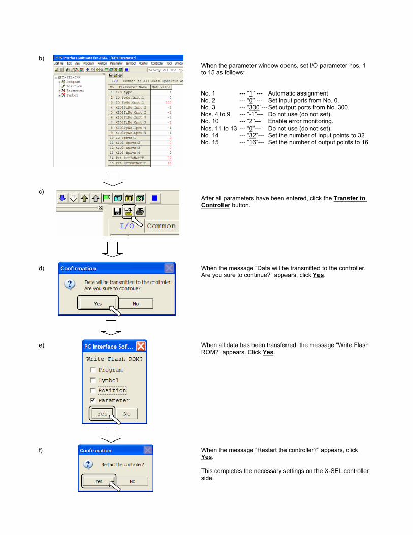
When the parameter window opens, set I/O parameter nos. 1 to 15 as follows:
No. 1 --- “1” --- Automatic assignment No. 2 --- “0” --- Set input ports from No. 0. No. 3 --- “300”--- Set output ports from No. 300. Nos. 4 to 9 --- “-1”--- Do not use (do not set). No. 10 --- “2”--- Enable error monitoring. Nos. 11 to 13 --- “0”--- Do not use (do not set). No. 14 --- “32”--- Set the number of input points to 32. No. 15 --- “16”--- Set the number of output points to 16.
After all parameters have been entered, click the Transfer to Controller button. When the message “Data will be transmitted to the controller. Are you sure to continue?” appears, click Yes. When all data has been transferred, the message “Write Flash ROM?” appears. Click Yes. When the message “Restart the controller?” appears, click Yes. This completes the necessary settings on the X-SEL controller side.
b) c) d) e) f)
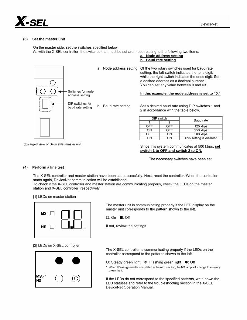
(3) Set the master unit
On the master side, set the switches specified below. As with the X-SEL controller, the switches that must be set are those relating to the following two items:
a. Node address setting b. Baud rate setting
a. Node address setting Of the two rotary switches used for baud rate
setting, the left switch indicates the tens digit, while the right switch indicates the ones digit. Set a desired address as a decimal number.
You can set any value between 0 and 63. In this example, the node address is set to “0.”
b. Baud rate setting Set a desired baud rate using DIP switches 1 and 2 in accordance with the table below.
DIP switch
1 2 Baud rate
OFF OFF 125 kbps ON OFF 250 kbps OFF ON 500 kbps ON ON This setting is disabled
Since this system communicates at 500 kbps, set switch 1 to OFF and switch 2 to ON.
The necessary switches have been set.
(4) Perform a line test
The X-SEL controller and master station have been set successfully. Next, reset the controller. When the controller starts again, DeviceNet communication will be established. To check if the X-SEL controller and master station are communicating properly, check the LEDs on the master station and X-SEL controller, respectively.
[1] LEDs on master station
The master unit is communicating properly if the LED display on the master unit corresponds to the pattern shown to the left.
: On : Off
If not, review the settings.
[2] LEDs on X-SEL controller The X-SEL controller is communicating properly if the LEDs on the controller correspond to the patterns shown to the left.
: Steady green light : Flashing green light : Off
* When I/O assignment is completed in the next section, the NS lamp will change to a steady green light.
If the LEDs do not correspond to the specified patterns, write down the LED statuses and refer to the troubleshooting section in the X-SEL DeviceNet Operation Manual.
Switches for node address setting DIP switches for baud rate setting
(Enlarged view of DeviceNet master unit)
DeviceNet
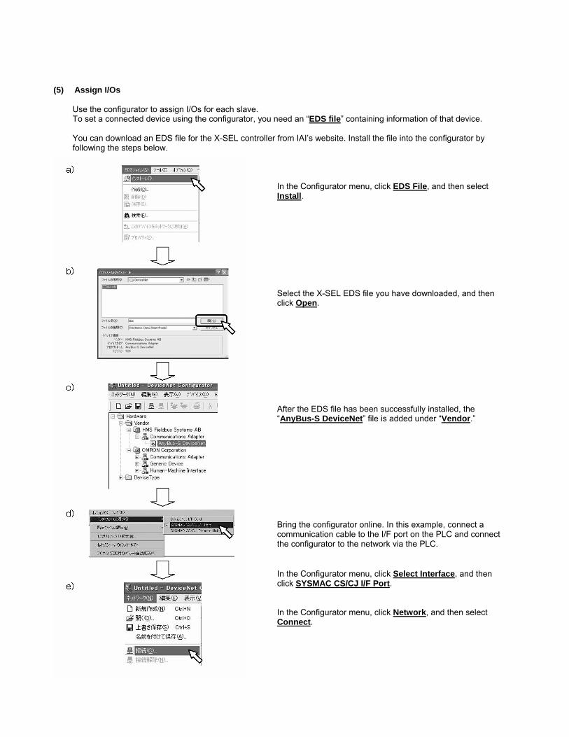
(5) Assign I/Os
Use the configurator to assign I/Os for each slave. To set a connected device using the configurator, you need an “EDS file” containing information of that device. You can download an EDS file for the X-SEL controller from IAI’s website. Install the file into the configurator by following the steps below.
In the Configurator menu, click EDS File, and then select Install. Select the X-SEL EDS file you have downloaded, and then click Open. After the EDS file has been successfully installed, the “AnyBus-S DeviceNet” file is added under “Vendor.”
Bring the configurator online. In this example, connect a communication cable to the I/F port on the PLC and connect the configurator to the network via the PLC. In the Configurator menu, click Select Interface, and then click SYSMAC CS/CJ I/F Port. In the Configurator menu, click Network, and then select Connect.
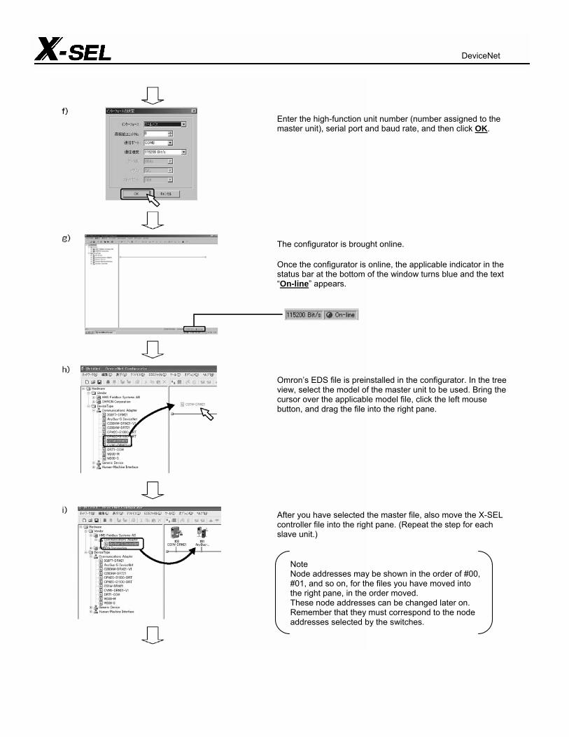
Enter the high-function unit number (number assigned to the master unit), serial port and baud rate, and then click OK.
The configurator is brought online. Once the configurator is online, the applicable indicator in the status bar at the bottom of the window turns blue and the text “On-line” appears.
Omron’s EDS file is preinstalled in the configurator. In the tree view, select the model of the master unit to be used. Bring the cursor over the applicable model file, click the left mouse button, and drag the file into the right pane.
After you have selected the master file, also move the X-SEL controller file into the right pane. (Repeat the step for each slave unit.)
Note Node addresses may be shown in the order of #00, #01, and so on, for the files you have moved into the right pane, in the order moved. These node addresses can be changed later on. Remember that they must correspond to the node addresses selected by the switches.
DeviceNet

Notes
An EDS file normally contains I/O data (numbers of bytes to be occupied). The numbers of bytes occupied by the X-SEL controller vary depending on the numbers of I/O points used. Therefore, the specific I/O data must be entered to set this information. Right-click the “AnyBus-S DeviceNet” icon to display the pop-up menu shown to the left. In this menu, click Properties. When the window shown to the left opens, click Edit.
In the OUT size and IN size fields under Poll, enter the numbers of bytes corresponding to the numbers of I/O points used. In this example, the X-SEL controller uses 16 output points and 32 input points. Accordingly, enter “4” bytes in the OUT size field and “2” bytes in the IN size field. * OUT and IN indicate the directions from the PLC side. They are
reversed on the X-SEL. When the applicable settings have been entered, click OK.
The numbers of bytes occupied by the X-SEL controller have been registered as Poll size information in the I/O Information tab. Confirm that the byte sizes are correct, and then click Close to close the window.
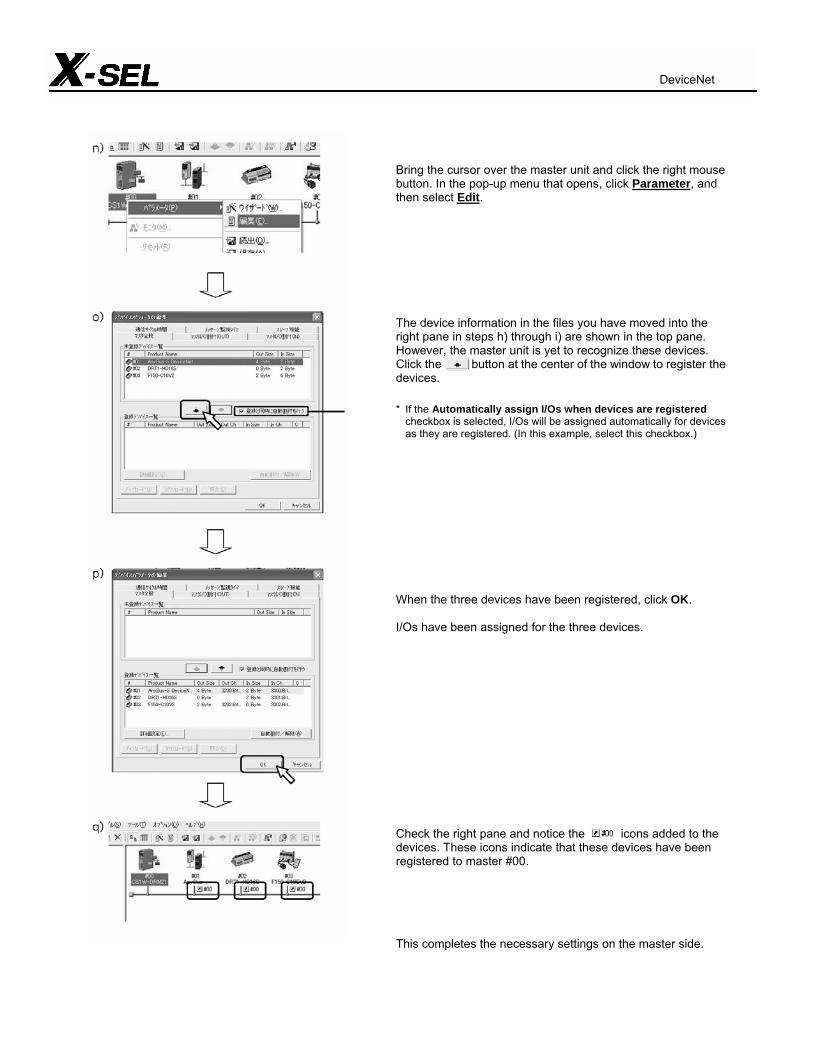
Bring the cursor over the master unit and click the right mouse button. In the pop-up menu that opens, click Parameter, and then select Edit.
The device information in the files you have moved into the right pane in steps h) through i) are shown in the top pane. However, the master unit is yet to recognize these devices. Click the button at the center of the window to register the devices. * If the Automatically assign I/Os when devices are registered
checkbox is selected, I/Os will be assigned automatically for devices as they are registered. (In this example, select this checkbox.)
When the three devices have been registered, click OK. I/Os have been assigned for the three devices.
Check the right pane and notice the icons added to the devices. These icons indicate that these devices have been registered to master #00.
This completes the necessary settings on the master side.
DeviceNet
(6) Start the system
After confirming that the line is connected properly, start the sequencer program to start the system.
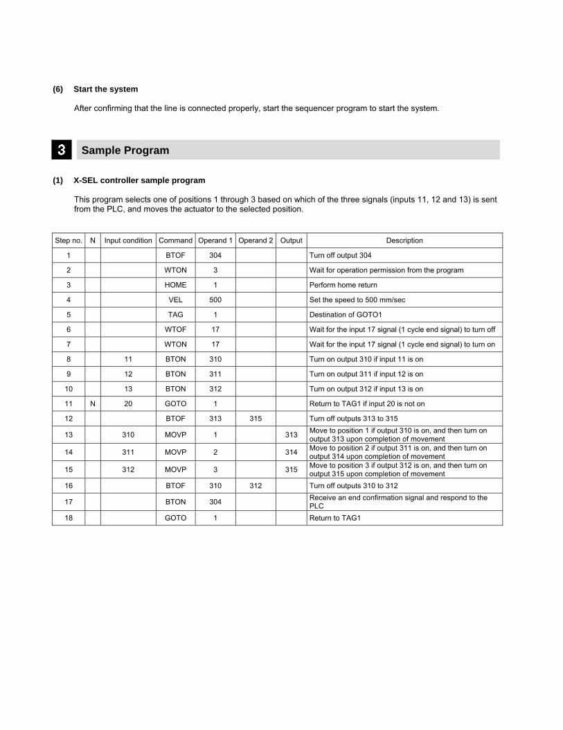
Sample Program (1) X-SEL controller sample program
This program selects one of positions 1 through 3 based on which of the three signals (inputs 11, 12 and 13) is sent from the PLC, and moves the actuator to the selected position.
Step no. N Input condition Command Operand 1 Operand 2 Output Description
1 BTOF 304 Turn off output 304
2 WTON 3 Wait for operation permission from the program
3 HOME 1 Perform home return
4 VEL 500 Set the speed to 500 mm/sec
5 TAG 1 Destination of GOTO1
6 WTOF 17 Wait for the input 17 signal (1 cycle end signal) to turn off
7 WTON 17 Wait for the input 17 signal (1 cycle end signal) to turn on
8 11 BTON 310 Turn on output 310 if input 11 is on
9 12 BTON 311 Turn on output 311 if input 12 is on
10 13 BTON 312 Turn on output 312 if input 13 is on
11 N 20 GOTO 1 Return to TAG1 if input 20 is not on
12 BTOF 313 315 Turn off outputs 313 to 315
13 310 MOVP 1 313 Move to position 1 if output 310 is on, and then turn on output 313 upon completion of movement
14 311 MOVP 2 314 Move to position 2 if output 311 is on, and then turn on output 314 upon completion of movement
15 312 MOVP 3 315 Move to position 3 if output 312 is on, and then turn on output 315 upon completion of movement
16 BTOF 310 312 Turn off outputs 310 to 312
17 BTON 304 Receive an end confirmation signal and respond to the PLC
18 GOTO 1 Return to TAG1
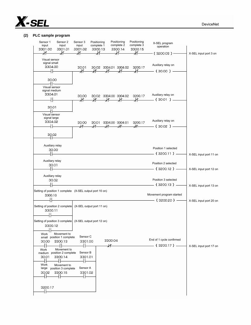
(2) PLC sample program
DeviceNet
Sensor 1 input
Sensor 2 input
Sensor 3 input
Positioning complete 1
Positioning complete 2
Positioning complete 3 X-SEL program
operation
X-SEL input port 3 on
X-SEL input port 11 on X-SEL input port 12 on X-SEL input port 13 on X-SEL input port 20 on X-SEL input port 17 on
Visual sensor signal small
Auxiliary relay on
Visual sensor signal medium
Auxiliary relay on
Auxiliary relay on
Visual sensor signal large
Auxiliary relay Position 1 selected
Auxiliary relay
Auxiliary relay
Position 2 selected
Position 3 selected
Setting of position 1 complete (X-SEL output port 10 on)Movement program started
Setting of position 2 complete (X-SEL output port 11 on)
Setting of position 3 complete (X-SEL output port 12 on)
Work small
Movement to position 1 complete Sensor C
End of 1 cycle confirmed
Work medium
Work large
Movement to position 2 complete
Movement to position 3 complete
Sensor B
Sensor A
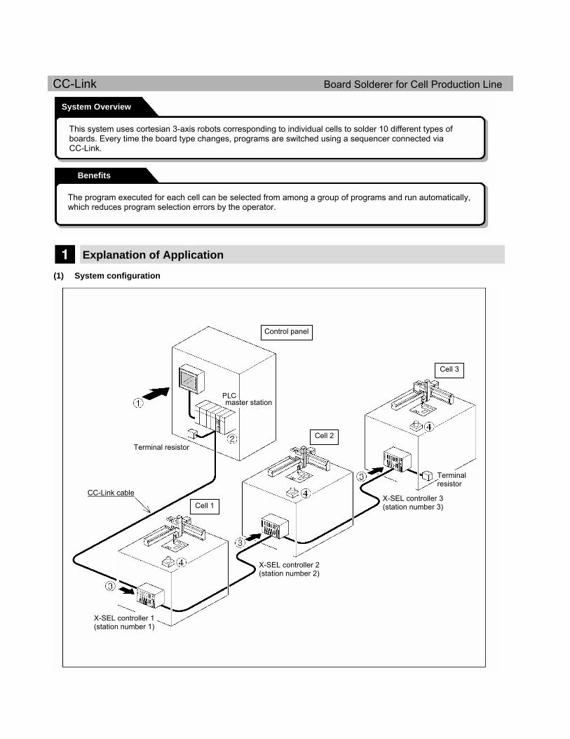
CC-Link Board Solderer for Cell Production Line
Explanation of Application (1) System configuration
System Overview
Benefits
This system uses cortesian 3-axis robots corresponding to individual cells to solder 10 different types of boards. Every time the board type changes, programs are switched using a sequencer connected via CC-Link.
The program executed for each cell can be selected from among a group of programs and run automatically, which reduces program selection errors by the operator.
Control panel
Terminal resistor
Terminal resistor
master station
CC-Link cable Cell 1
Cell 2
Cell 3
X-SEL controller 1 (station number 1)
X-SEL controller 2 (station number 2)
X-SEL controller 3 (station number 3)
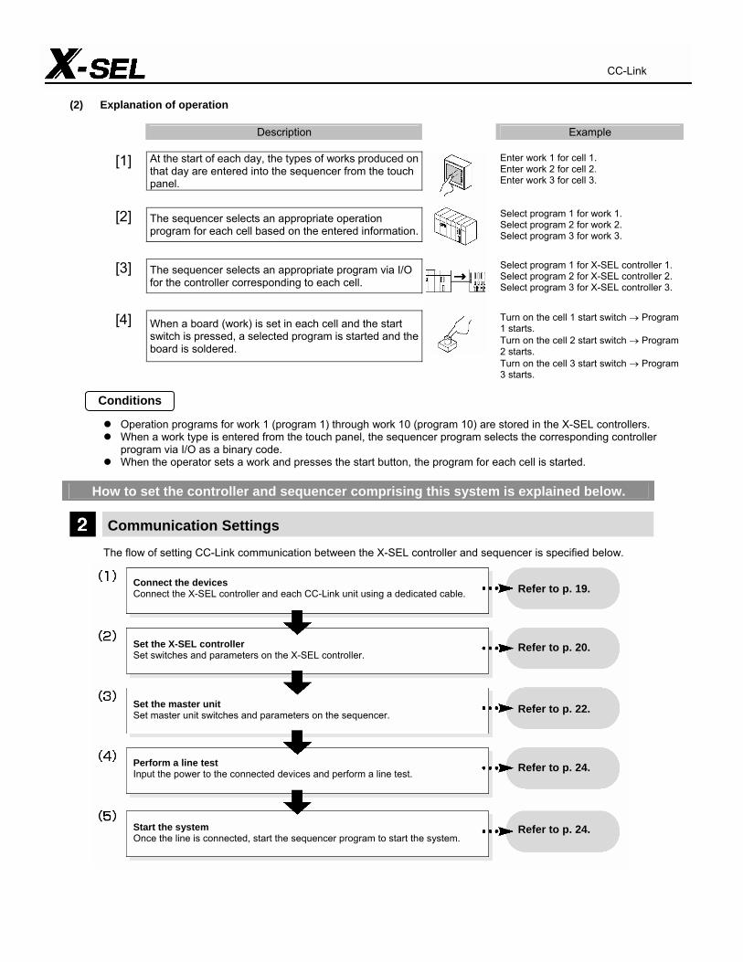
(2) Explanation of operation
Description Example
[1] At the start of each day, the types of works produced on that day are entered into the sequencer from the touch panel.
Enter work 1 for cell 1. Enter work 2 for cell 2. Enter work 3 for cell 3.
[2] The sequencer selects an appropriate operation program for each cell based on the entered information.
Select program 1 for work 1. Select program 2 for work 2. Select program 3 for work 3.
[3] The sequencer selects an appropriate program via I/O for the controller corresponding to each cell.
Select program 1 for X-SEL controller 1. Select program 2 for X-SEL controller 2. Select program 3 for X-SEL controller 3.
When a board (work) is set in each cell and the start switch is pressed, a selected program is started and the board is soldered.
[4]
Turn on the cell 1 start switch → Program 1 starts. Turn on the cell 2 start switch → Program 2 starts. Turn on the cell 3 start switch → Program 3 starts.
Operation programs for work 1 (program 1) through work 10 (program 10) are stored in the X-SEL controllers. When a work type is entered from the touch panel, the sequencer program selects the corresponding controller
program via I/O as a binary code. When the operator sets a work and presses the start button, the program for each cell is started.
How to set the controller and sequencer comprising this system is explained below.
Communication Settings
The flow of setting CC-Link communication between the X-SEL controller and sequencer is specified below.
Conditions
CC-Link
Connect the devices Connect the X-SEL controller and each CC-Link unit using a dedicated cable. Set the X-SEL controller Set switches and parameters on the X-SEL controller. Set the master unit Set master unit switches and parameters on the sequencer. Perform a line test Input the power to the connected devices and perform a line test. Start the system Once the line is connected, start the sequencer program to start the system.
Refer to p. 19. Refer to p. 20. Refer to p. 22. Refer to p. 24. Refer to p. 24.

(2) Set the X-SEL controller
On the X-SEL controller, set [1] switches and [2] parameters.
[1] Setting switches The switches that must be set are those relating to the following items: a. Station number setting b. Baud rate setting
a. Station number setting Set a desired station number using the rotary switches for
station number setting (tens digit and ones digit). You can set any value between 1 and 64 (corresponding to stations 1 through 64).
In this example, set the switches as follows:
X-SEL controller 1 → Station number 1 X-SEL controller 2 → Station number 2 X-SEL controller 3 → Station number 3
b. Baud rate setting One of five baud rates from 0 (156 kbps) to 4 (10 Mbps) can
be set. Make sure that the baud rate set on the X-SEL controller
corresponds to the baud rate set on the sequencer. (Enlarged view of CC-Link connection board)
Since this system communicates at 156 kbps, set the switch to “0.”
The necessary switches have been set.
[2] Setting parameters The X-SEL controller provides a number of parameters for setting various aspects of operation. To connect the X-SEL controller to CC-Link, the following I/O parameters must be set using the X-SEL PC
software (model: IA-101-X-MW).
I/O parameter no. Parameter name Description
1 I/O port assignment type (I/O type) Set whether to use fixed or automatic assignment of I/O ports.
2 Standard I/O input port starting number (IO TpNo. Iprt:1)
Set the port number for the first input port used in I/O communication.
3 Standard I/O output port starting number (IO TpNo. Oprt:1)
Set the port number for the first output port used in I/O communication.
4 ~ 9 Extended I/O input (output) port starting number (XIO1TpNo. Iprt (Oprt))
These parameters are set when an extended I/O board is used.
10 ~ 13 Standard (extended) I/O error monitor (IO (XIO) Sprvs)
Set I/O error monitor.
14 Number of network I/F card remote input ports (Prt RmtInNetIF)
Set the number of CC-Link input points as a multiple of 16 (n) (16 ≤ n ≤ 256).
15 Number of network I/F card remote output ports (Prt RmtOutNetIF)
Set the number of CC-Link output points as a multiple of 16 (m) (16 ≤ m ≤ 256).
* The number of occupied stations varies depending on the numbers of points set in parameter nos. 14 and 15. For details, refer to the X-SEL CC-Link Operation Manual.
The steps to set parameters are explained below. * The same procedure applies to controllers 1 through 3.
Connect the PC with the X-SEL controller using a dedicated PC connection cable, turn on the controller power, and then start the X-SEL PC software. After the software has started, click Parameter in the menu bar, and then select the Edit sub-menu.
a)
CC-Link
Cable connector Rotary switch for baud rate setting
Rotary switch for station number setting (tens digit)
Rotary switch for station number setting (ones digit) Monitor LEDs

When the parameter window opens, set I/O parameter nos. 1 to 15 as follows:
No. 1 --- “1” --- Automatic assignment No. 2 --- “0” --- Set input ports from No. 0. No. 3 --- “300” --- Set output ports from No. 300. Nos. 4 to 9 --- “-1” --- Do not use (do not set). No. 10 --- “2” --- Enable error monitoring. Nos. 11 to 13 --- “0” --- Do not use (do not set). No. 14 --- “96” --- Set the number of input points to 96. No. 15 --- “96” --- Set the number of output points to 96.
After all parameters have been entered, click the Transfer to Controller button. When the message “Data will be transmitted to the controller. Are you sure to continue?” appears, click Yes. When all data has been transferred, the message “Write Flash ROM?” appears. Click Yes. When the message “Restart the controller?” appears, click Yes. This completes the necessary settings on the X-SEL controller side.
b) c) d) e) f)
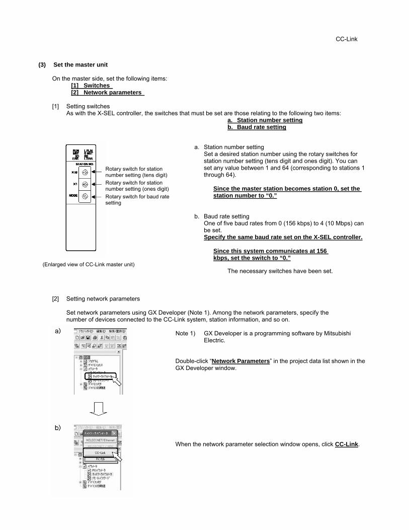
(3) Set the master unit
On the master side, set the following items: [1] Switches [2] Network parameters
[1] Setting switches As with the X-SEL controller, the switches that must be set are those relating to the following two items:
a. Station number setting b. Baud rate setting
a. Station number setting Set a desired station number using the rotary switches for
station number setting (tens digit and ones digit). You can set any value between 1 and 64 (corresponding to stations 1 through 64).
Since the master station becomes station 0, set the station number to “0.”
b. Baud rate setting One of five baud rates from 0 (156 kbps) to 4 (10 Mbps) can
be set. Specify the same baud rate set on the X-SEL controller.
Since this system communicates at 156 kbps, set the switch to “0.”
(Enlarged view of CC-Link master unit) The necessary switches have been set.
[2] Setting network parameters
Set network parameters using GX Developer (Note 1). Among the network parameters, specify the number of devices connected to the CC-Link system, station information, and so on.
Note 1) GX Developer is a programming software by Mitsubishi
Electric.
Double-click “Network Parameters” in the project data list shown in the GX Developer window.
When the network parameter selection window opens, click CC-Link.
CC-Link
Rotary switch for station number setting (tens digit)
Rotary switch for station number setting (ones digit)
Rotary switch for baud rate setting
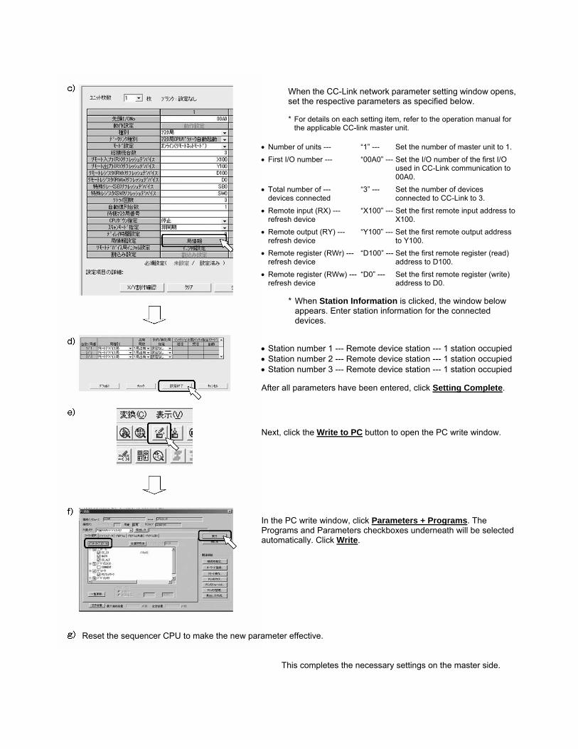
When the CC-Link network parameter setting window opens, set the respective parameters as specified below. * For details on each setting item, refer to the operation manual for
the applicable CC-link master unit.
• Number of units --- “1” --- Set the number of master unit to 1.
• First I/O number --- “00A0” --- Set the I/O number of the first I/O used in CC-Link communication to 00A0.
• Total number of --- “3” --- Set the number of devices devices connected connected to CC-Link to 3.
• Remote input (RX) --- “X100” --- Set the first remote input address to refresh device X100.
• Remote output (RY) --- “Y100” --- Set the first remote output address refresh device to Y100.
• Remote register (RWr) --- “D100” --- Set the first remote register (read) refresh device address to D100.
• Remote register (RWw) --- “D0” --- Set the first remote register (write) refresh device address to D0.
* When Station Information is clicked, the window below appears. Enter station information for the connected devices.
• Station number 1 --- Remote device station --- 1 station occupied • Station number 2 --- Remote device station --- 1 station occupied • Station number 3 --- Remote device station --- 1 station occupied After all parameters have been entered, click Setting Complete. Next, click the Write to PC button to open the PC write window. In the PC write window, click Parameters + Programs. The Programs and Parameters checkboxes underneath will be selected automatically. Click Write.
Reset the sequencer CPU to make the new parameter effective.
This completes the necessary settings on the master side.
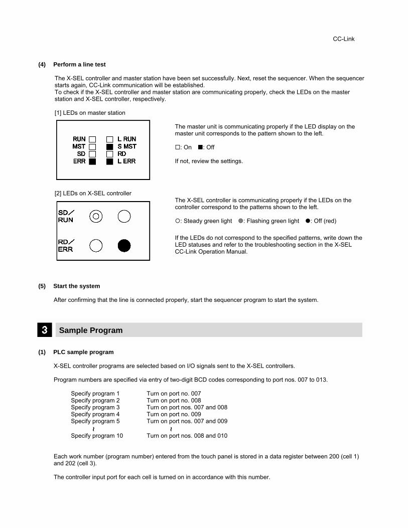
(4) Perform a line test
The X-SEL controller and master station have been set successfully. Next, reset the sequencer. When the sequencer starts again, CC-Link communication will be established. To check if the X-SEL controller and master station are communicating properly, check the LEDs on the master station and X-SEL controller, respectively.
[1] LEDs on master station
The master unit is communicating properly if the LED display on the master unit corresponds to the pattern shown to the left.
: On : Off
If not, review the settings.
[2] LEDs on X-SEL controller The X-SEL controller is communicating properly if the LEDs on the controller correspond to the patterns shown to the left.
: Steady green light : Flashing green light : Off (red)
If the LEDs do not correspond to the specified patterns, write down the LED statuses and refer to the troubleshooting section in the X-SEL CC-Link Operation Manual.
(5) Start the system
After confirming that the line is connected properly, start the sequencer program to start the system.
Sample Program (1) PLC sample program
X-SEL controller programs are selected based on I/O signals sent to the X-SEL controllers. Program numbers are specified via entry of two-digit BCD codes corresponding to port nos. 007 to 013.
Specify program 1 Turn on port no. 007 Specify program 2 Turn on port no. 008 Specify program 3 Turn on port nos. 007 and 008 Specify program 4 Turn on port no. 009 Specify program 5 Turn on port nos. 007 and 009 Specify program 10 Turn on port nos. 008 and 010
Each work number (program number) entered from the touch panel is stored in a data register between 200 (cell 1) and 202 (cell 3).
The controller input port for each cell is turned on in accordance with this number.
CC-Link
~ ~
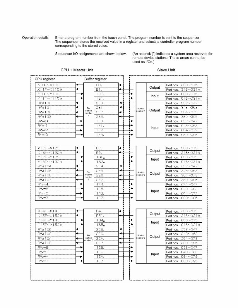
Operation details Enter a program number from the touch panel. The program number is sent to the sequencer. The sequencer stores the received value in a register and selects a controller program number
corresponding to the stored value.
Sequencer I/O assignments are shown below. (An asterisk (*) indicates a system area reserved for remote device stations. These areas cannot be used as I/Os.)
CPU + Master Unit Slave Unit
CPU register Buffer register
For station number
1
For station number
2
For station
number 3
Station number 1
Station number 2
Station number 3
Output
Input
Output
Input
Output
Input
Output
Input
Output
Input
Output
Input
Port nos. Port nos. Port nos. Port nos. Port nos. Port nos. Port nos. Port nos. Port nos. Port nos. Port nos. Port nos. Port nos. Port nos. Port nos. Port nos. Port nos. Port nos. Port nos. Port nos. Port nos. Port nos. Port nos. Port nos. Port nos. Port nos. Port nos. Port nos. Port nos. Port nos. Port nos. Port nos. Port nos. Port nos. Port nos. Port nos.

The program below is the portion of the sample program for selecting the program for X-SEL controller 1. The program number selected on the touch panel is stored in data register 200, and the program for X-SEL controller 1 is selected based on the stored value. The programs for X-SEL controllers 2 and 3 are selected in the same manner, except that the addresses and flag numbers are different.
No program Specify program 1 for controller 1 Specify program 2 for controller 1 Specify program 3 for controller 1 Specify program 4 for controller 1 Specify program 5 for controller 1 Specify program 6 for controller 1 Specify program 7 for controller 1 Specify program 8 for controller 1 Specify program 9 for controller 1 Specify program 10 for controller 1
Turn on port no. 007 (Program selection 1)
Turn on port no. 008 (Program selection 2)
Turn on port no. 009 (Program selection 4)
Turn on port no. 010 (Program selection 8)
CC-Link
Ethernet Work Sorter/Pick-up
Explanation of Application (1) System configuration
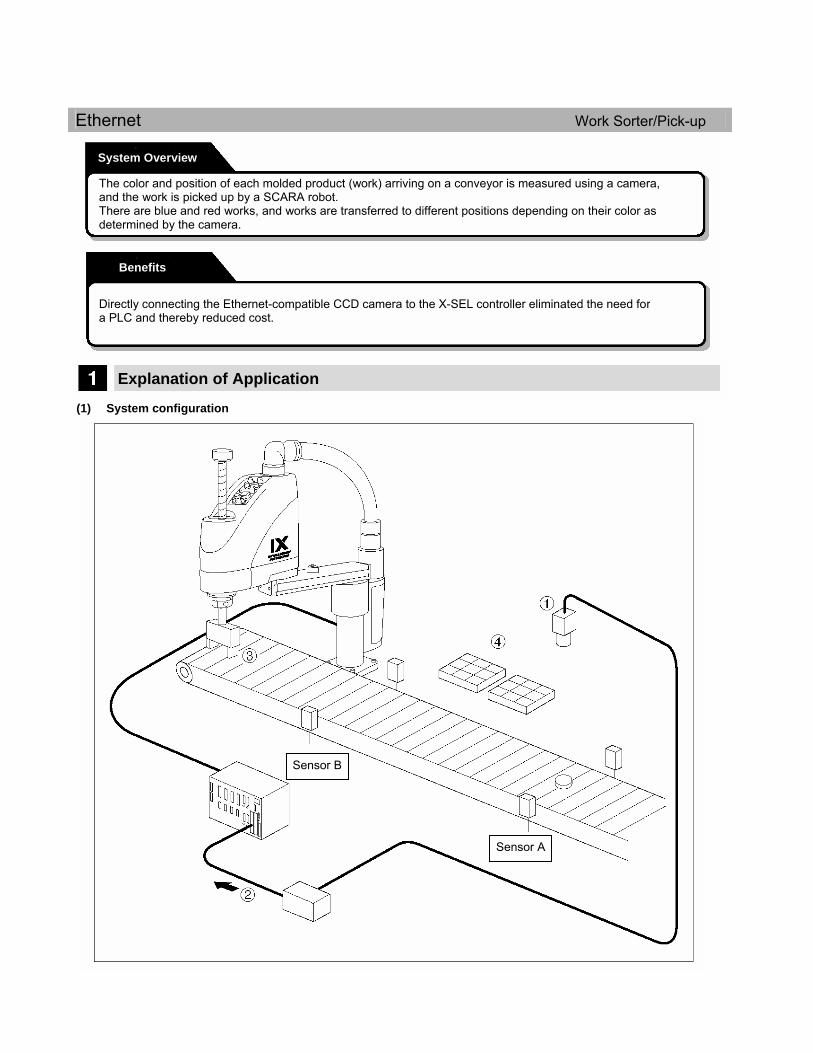
System Overview
The color and position of each molded product (work) arriving on a conveyor is measured using a camera, and the work is picked up by a SCARA robot. There are blue and red works, and works are transferred to different positions depending on their color as determined by the camera.
Benefits
Directly connecting the Ethernet-compatible CCD camera to the X-SEL controller eliminated the need for a PLC and thereby reduced cost.
Sensor B
Sensor A

(2) Explanation of operation
Description Example
[1] The moment a work passes by sensor A, the camera measures the position and color of the work.
The red work moves on the conveyor and passes the X coordinate: -350 position.
[2] The measurement result is sent from the camera to the X-SEL controller via Ethernet.
The controller recognizes the coordinate information (-350) and color information (red) of the work via the program.
[3] The SCARA robot stands by near sensor B based on the measurement data from the camera.
The SCARA robot moves to the Y coordinate: -350 position and stands by.
[4] When sensor B detects the work, the conveyor pauses momentarily. The SCARA robot picks up the work and transfers it to the pallet corresponding to the applicable color.
The SCARA robot picks up the red work and transfers it to the red pallet.
The camera connected is DVT’s SmartImage Sensor. The camera measures each work as soon as the work is detected by sensor A. The camera measures two items: [1] Y coordinate and [2] color (red or blue) of the work. The SCARA robot changes its standby position depending on the measurement data received from the camera,
and waits for the work to arrive. The SCARA robot picks up the work as soon as the work is detected by sensor B. The SCARA robot transfers the picked-up work to the pallet corresponding to the applicable color based on the
data sent from the camera.
How to set the X-SEL controller and camera comprising this system is explained below.
Communication Settings
The flow of setting Ethernet communication between the X-SEL controller and CCD camera is specified below.
Conditions
Ethernet
Connect the devices Connect the X-SEL controller with the CCD camera using a LAN cable (RJ-45). Set the X-SEL controller Enter X-SEL controller parameters and program. Set the camera Set the camera and enter a program. Perform a line test Input the power to the connected devices and perform a line test. Start the system After confirming that the camera and X-SEL controller are connected to Ethernet, start both communication programs to establish communication between the two and start the system.
Refer to p. 29. Refer to p. 30.
Refer to p. 33. Refer to p. 35. Refer to p. 35.
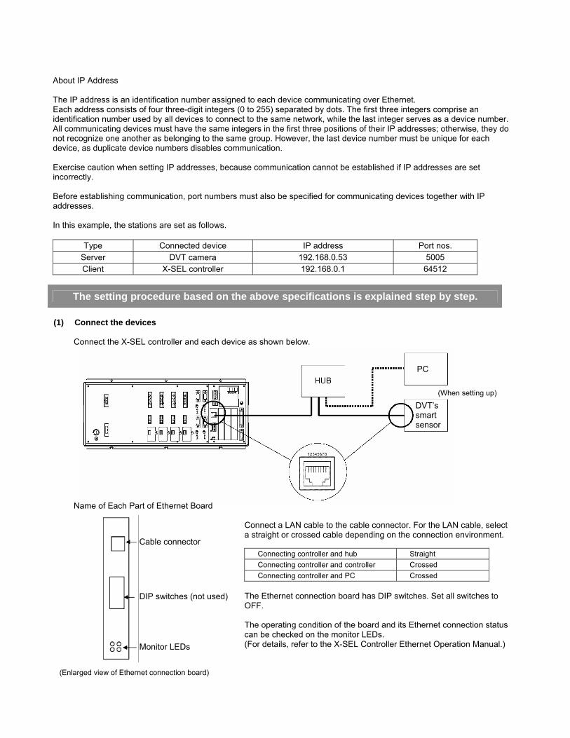
About IP Address The IP address is an identification number assigned to each device communicating over Ethernet. Each address consists of four three-digit integers (0 to 255) separated by dots. The first three integers comprise an identification number used by all devices to connect to the same network, while the last integer serves as a device number. All communicating devices must have the same integers in the first three positions of their IP addresses; otherwise, they do not recognize one another as belonging to the same group. However, the last device number must be unique for each device, as duplicate device numbers disables communication. Exercise caution when setting IP addresses, because communication cannot be established if IP addresses are set incorrectly. Before establishing communication, port numbers must also be specified for communicating devices together with IP addresses. In this example, the stations are set as follows.
Type Connected device IP address Port nos. Server DVT camera 192.168.0.53 5005 Client X-SEL controller 192.168.0.1 64512
The setting procedure based on the above specifications is explained step by step. (1) Connect the devices
Connect the X-SEL controller and each device as shown below.
Name of Each Part of Ethernet Board
Connect a LAN cable to the cable connector. For the LAN cable, select a straight or crossed cable depending on the connection environment.
Connecting controller and hub Straight Connecting controller and controller Crossed Connecting controller and PC Crossed
The Ethernet connection board has DIP switches. Set all switches to OFF.
The operating condition of the board and its Ethernet connection status can be checked on the monitor LEDs. (For details, refer to the X-SEL Controller Ethernet Operation Manual.)
(Enlarged view of Ethernet connection board)
PC
(When setting up)
DVT’s smart sensor
Cable connector DIP switches (not used) Monitor LEDs
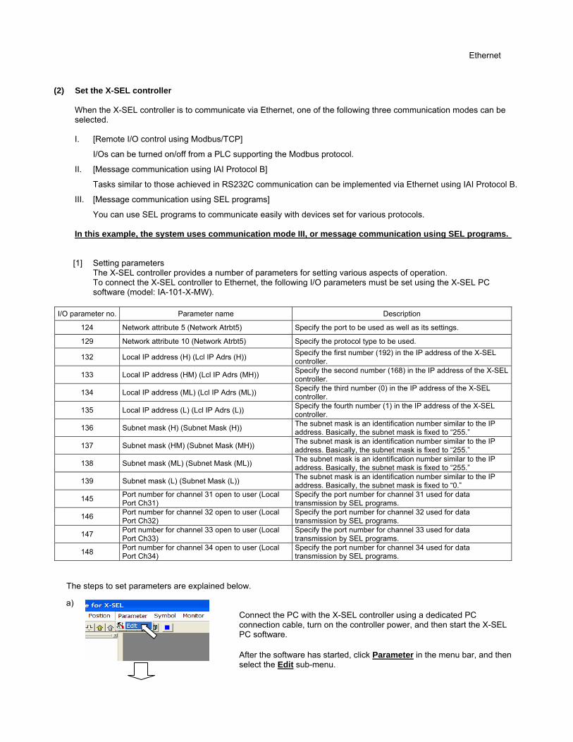
(2) Set the X-SEL controller
When the X-SEL controller is to communicate via Ethernet, one of the following three communication modes can be selected. I. [Remote I/O control using Modbus/TCP]
I/Os can be turned on/off from a PLC supporting the Modbus protocol.
II. [Message communication using IAI Protocol B]
Tasks similar to those achieved in RS232C communication can be implemented via Ethernet using IAI Protocol B.
III. [Message communication using SEL programs]
You can use SEL programs to communicate easily with devices set for various protocols. In this example, the system uses communication mode III, or message communication using SEL programs.
[1] Setting parameters The X-SEL controller provides a number of parameters for setting various aspects of operation. To connect the X-SEL controller to Ethernet, the following I/O parameters must be set using the X-SEL PC
software (model: IA-101-X-MW).
I/O parameter no. Parameter name Description
124 Network attribute 5 (Network Atrbt5) Specify the port to be used as well as its settings.
129 Network attribute 10 (Network Atrbt5) Specify the protocol type to be used.
132 Local IP address (H) (Lcl IP Adrs (H)) Specify the first number (192) in the IP address of the X-SEL controller.
133 Local IP address (HM) (Lcl IP Adrs (MH)) Specify the second number (168) in the IP address of the X-SEL controller.
134 Local IP address (ML) (Lcl IP Adrs (ML)) Specify the third number (0) in the IP address of the X-SEL controller.
135 Local IP address (L) (Lcl IP Adrs (L)) Specify the fourth number (1) in the IP address of the X-SEL controller.
136 Subnet mask (H) (Subnet Mask (H)) The subnet mask is an identification number similar to the IP address. Basically, the subnet mask is fixed to “255.”
137 Subnet mask (HM) (Subnet Mask (MH)) The subnet mask is an identification number similar to the IP address. Basically, the subnet mask is fixed to “255.”
138 Subnet mask (ML) (Subnet Mask (ML)) The subnet mask is an identification number similar to the IP address. Basically, the subnet mask is fixed to “255.”
139 Subnet mask (L) (Subnet Mask (L)) The subnet mask is an identification number similar to the IP address. Basically, the subnet mask is fixed to “0.”
145 Port number for channel 31 open to user (Local Port Ch31)
Specify the port number for channel 31 used for data transmission by SEL programs.
146 Port number for channel 32 open to user (Local Port Ch32)
Specify the port number for channel 32 used for data transmission by SEL programs.
147 Port number for channel 33 open to user (Local Port Ch33)
Specify the port number for channel 33 used for data transmission by SEL programs.
148 Port number for channel 34 open to user (Local Port Ch34)
Specify the port number for channel 34 used for data transmission by SEL programs.
The steps to set parameters are explained below.
Connect the PC with the X-SEL controller using a dedicated PC connection cable, turn on the controller power, and then start the X-SEL PC software. After the software has started, click Parameter in the menu bar, and then select the Edit sub-menu.
a)
Ethernet
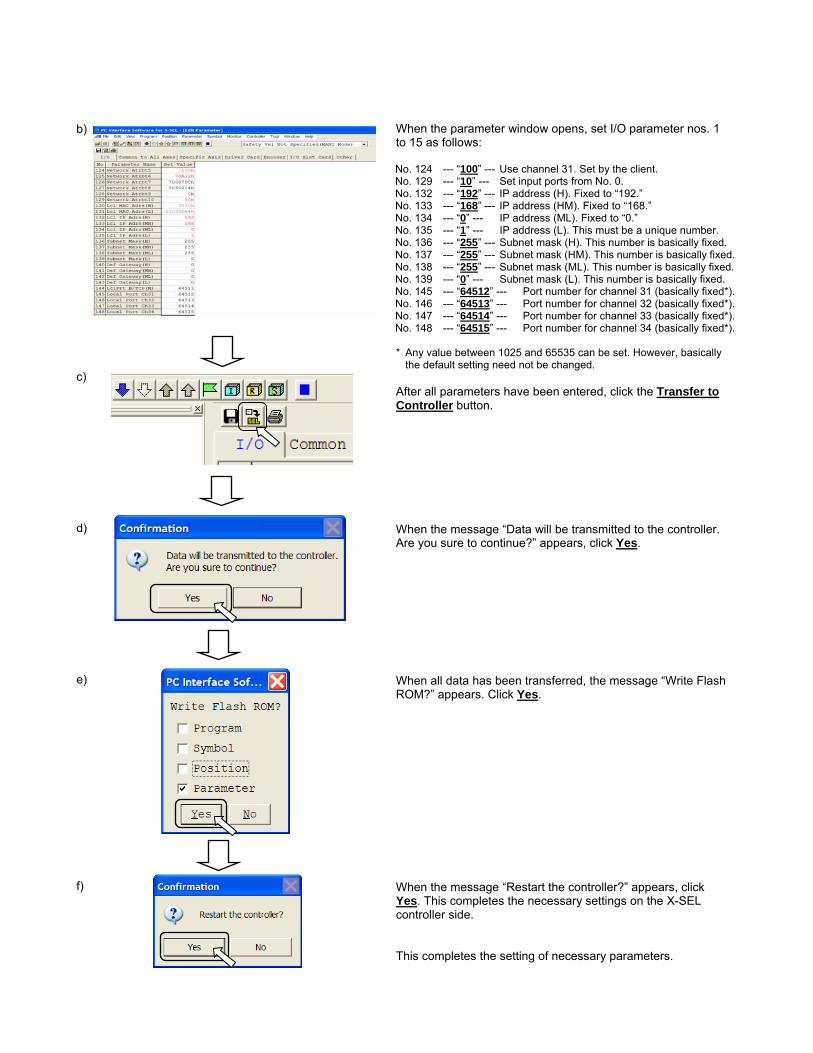
When the parameter window opens, set I/O parameter nos. 1 to 15 as follows: No. 124 --- “100” --- Use channel 31. Set by the client. No. 129 --- “10” --- Set input ports from No. 0. No. 132 --- “192” --- IP address (H). Fixed to “192.” No. 133 --- “168” --- IP address (HM). Fixed to “168.” No. 134 --- “0” --- IP address (ML). Fixed to “0.” No. 135 --- “1” --- IP address (L). This must be a unique number. No. 136 --- “255” --- Subnet mask (H). This number is basically fixed. No. 137 --- “255” --- Subnet mask (HM). This number is basically fixed. No. 138 --- “255” --- Subnet mask (ML). This number is basically fixed. No. 139 --- “0” --- Subnet mask (L). This number is basically fixed. No. 145 --- “64512” --- Port number for channel 31 (basically fixed*). No. 146 --- “64513” --- Port number for channel 32 (basically fixed*). No. 147 --- “64514” --- Port number for channel 33 (basically fixed*). No. 148 --- “64515” --- Port number for channel 34 (basically fixed*). * Any value between 1025 and 65535 can be set. However, basically
the default setting need not be changed. After all parameters have been entered, click the Transfer to Controller button. When the message “Data will be transmitted to the controller. Are you sure to continue?” appears, click Yes. When all data has been transferred, the message “Write Flash ROM?” appears. Click Yes. When the message “Restart the controller?” appears, click Yes. This completes the necessary settings on the X-SEL controller side.
This completes the setting of necessary parameters.
b) c) d) e) f)
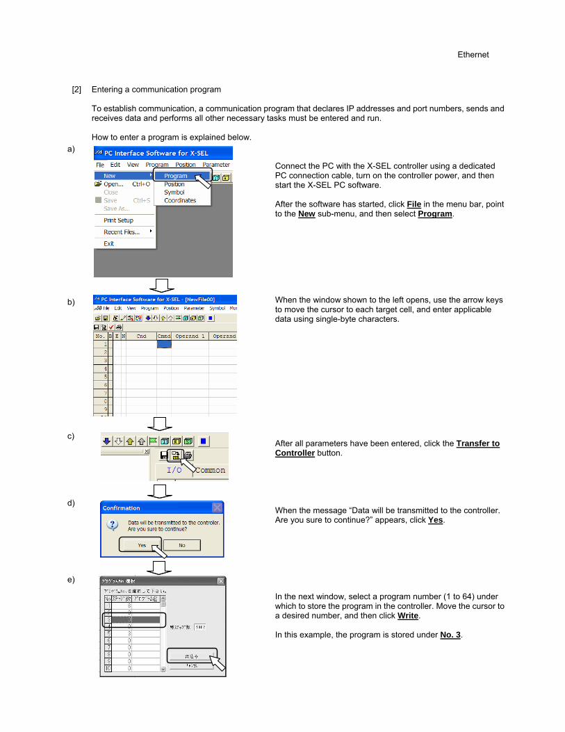
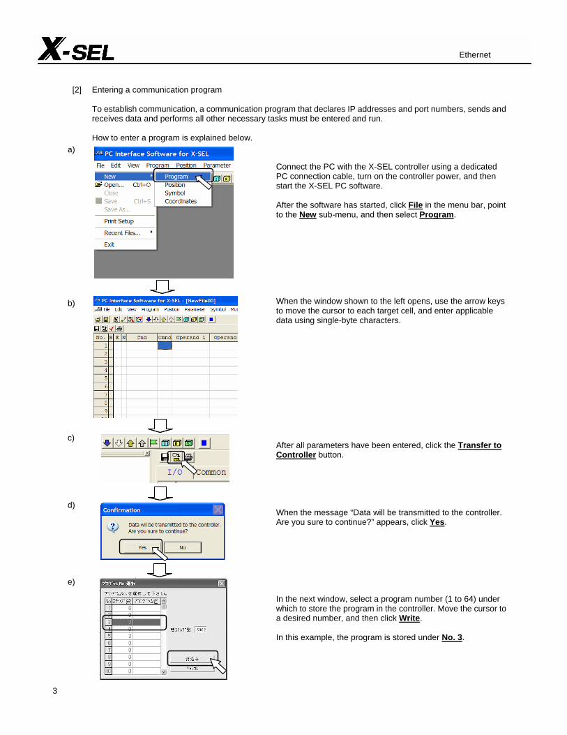
[2] Entering a communication program
To establish communication, a communication program that declares IP addresses and port numbers, sends and receives data and performs all other necessary tasks must be entered and run.
How to enter a program is explained below.
Connect the PC with the X-SEL controller using a dedicated PC connection cable, turn on the controller power, and then start the X-SEL PC software.
After the software has started, click File in the menu bar, point to the New sub-menu, and then select Program.
When the window shown to the left opens, use the arrow keys to move the cursor to each target cell, and enter applicable data using single-byte characters.
After all parameters have been entered, click the Transfer to Controller button. When the message “Data will be transmitted to the controller. Are you sure to continue?” appears, click Yes.
In the next window, select a program number (1 to 64) under which to store the program in the controller. Move the cursor to a desired number, and then click Write.
In this example, the program is stored under No. 3.
a) b) c) d) e)
Ethernet

When all data has been transferred, the message “Write Flash ROM?” appears. Click Yes. The program has been entered.
(3) Setting the camera
To enable the camera to communicate with the X-SEL controller via Ethernet, perform the following settings using the supplied software (FRAMEWORK): [1] Specify communication settings on the PC to allow it to communicate with the camera. [2] Start FRAMEWORK installed in the PC to specify various settings for the camera. The specifics of [1] and [2] are explained below. [1] To connect the PC to Ethernet, you must set the PC’s “IP address” and “subnet mask.”
Click the Windows Start menu, point to Settings, point to Control Panel, point to Network Connections, and then select Local Area Network.
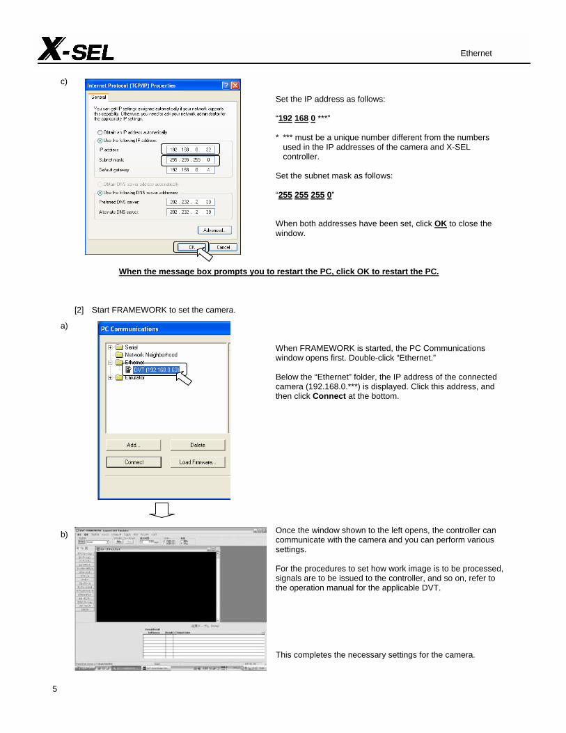
Click Internet Protocol (TCP/IP), and then click Properties.
f)
a) b)

Set the IP address as follows:
“192 168 0 ***”
* *** must be a unique number different from the numbers used in the IP addresses of the camera and X-SEL controller.
Set the subnet mask as follows:
“255 255 255 0”
When both addresses have been set, click OK to close the window.
When the message box prompts you to restart the PC, click OK to restart the PC.
[2] Start FRAMEWORK to set the camera.
When FRAMEWORK is started, the PC Communications window opens first. Double-click “Ethernet.”
Below the “Ethernet” folder, the IP address of the connected camera (192.168.0.***) is displayed. Click this address, and then click Connect at the bottom.
Once the window shown to the left opens, the controller can communicate with the camera and you can perform various settings.
For the procedures to set how work image is to be processed, signals are to be issued to the controller, and so on, refer to the operation manual for the applicable DVT.
This completes the necessary settings for the camera.
Ethernet
c)
a) b)
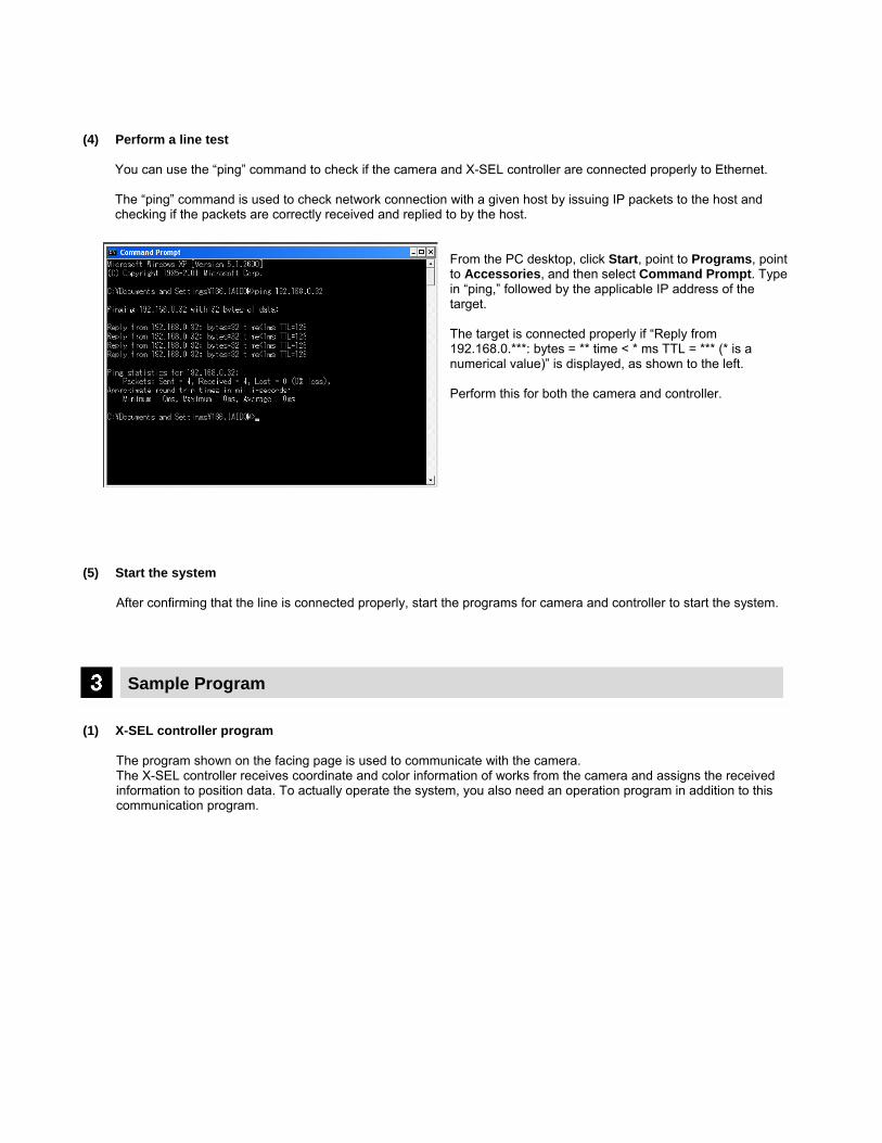
(4) Perform a line test
You can use the “ping” command to check if the camera and X-SEL controller are connected properly to Ethernet.
The “ping” command is used to check network connection with a given host by issuing IP packets to the host and checking if the packets are correctly received and replied to by the host.
From the PC desktop, click Start, point to Programs, point to Accessories, and then select Command Prompt. Type in “ping,” followed by the applicable IP address of the target.
The target is connected properly if “Reply from 192.168.0.***: bytes = ** time < * ms TTL = *** (* is a numerical value)” is displayed, as shown to the left.
Perform this for both the camera and controller.
(5) Start the system
After confirming that the line is connected properly, start the programs for camera and controller to start the system.
Sample Program (1) X-SEL controller program
The program shown on the facing page is used to communicate with the camera. The X-SEL controller receives coordinate and color information of works from the camera and assigns the received information to position data. To actually operate the system, you also need an operation program in addition to this communication program.
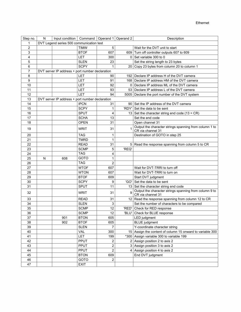
Step no. N Input condition Command Operand 1 Operand 2 Description
1 DVT Legend series 500 communication test 2 TIMW 5 Wait for the DVT unit to start 3 BTOF 607 609 Turn off controller outputs 607 to 609 4 LET 300 0 Set variable 300 to 0 5 SLEN 23 Set the string length to 23 bytes 6 SCPY 1 20 Copy 23 bytes from column 20 to column 1 7 DVT server IP address + port number declaration 8 LET 90 192 Declare IP address H of the DVT camera 9 LET 91 168 Declare IP address HM of the DVT camera
10 LET 92 0 Declare IP address ML of the DVT camera 11 LET 93 53 Declare IP address L of the DVT camera 12 LET 94 5005 Declare the port number of the DVT system 13 DVT server IP address + port number declaration 14 IPCN 31 90 Set the IP address of the DVT camera 15 SCPY 1 'RDY' Set the data to be sent 16 SPUT 4 13 Set the character string end code (13 = CR) 17 SCHA 13 Set the end code 18 OPEN 31 Open channel 31
19 WRIT 31 1 Output the character strings spanning from column 1 to CR via channel 31
20 TAG 1 Destination of GOTO in step 25 21 TMRD 1 22 READ 31 5 Read the response spanning from column 5 to CR 23 SCMP 5 'REQ' 24 TAG 4 25 N 608 GOTO 1 26 TAG 2 27 WTOF 607 Wait for DVT-TRRI to turn off 28 WTON 607 Wait for DVT-TRRI to turn on 29 BTOF 609 Start DVT judgment 30 SCPY 9 'GO' Set the data to be sent 31 SPUT 11 13 Set the character string end code
32 WRIT 31 9 Output the character strings spanning from column 9 to CR via channel 31
33 READ 31 12 Read the response spanning from column 12 to CR 34 SLEN 3 Set the number of characters to be compared 35 SCMP 12 'RED' Check for RED response 36 SCMP 12 'BLU' Check for BLUE response 37 901 BTON 605 LED judgment 38 902 BTOF 605 BLUE judgment 39 SLEN 7 Y-coordinate character string 40 VAL 300 15 Assign the content of column 15 onward to variable 30041 LET 199 *300 Assign variable 300 to variable 199 42 PPUT 2 2 Assign position 2 to axis 2 43 PPUT 2 3 Assign position 3 to axis 2 44 PPUT 2 4 Assign position 4 to axis 2 45 BTON 609 End DVT judgment 46 GOTO 2 47 EXIT
Ethernet
Protocol Communication (RS232C) Wood Length Specifier/Cutter
Explanation of Application (1) System configuration
System Overview
Benefits
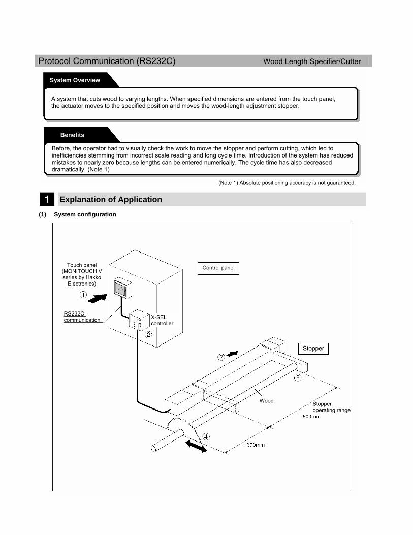
A system that cuts wood to varying lengths. When specified dimensions are entered from the touch panel, the actuator moves to the specified position and moves the wood-length adjustment stopper.
Before, the operator had to visually check the work to move the stopper and perform cutting, which led to inefficiencies stemming from incorrect scale reading and long cycle time. Introduction of the system has reduced mistakes to nearly zero because lengths can be entered numerically. The cycle time has also decreased dramatically. (Note 1)
(Note 1) Absolute positioning accuracy is not guaranteed.
Touch panel (MONITOUCH V series by Hakko
Electronics)
RS232C communication
Stopper operating range
Stopper
Wood
X-SEL controller
Control panel
3
[2] Entering a communication program
To establish communication, a communication program that declares IP addresses and port numbers, sends and receives data and performs all other necessary tasks must be entered and run.
How to enter a program is explained below.
Connect the PC with the X-SEL controller using a dedicated PC connection cable, turn on the controller power, and then start the X-SEL PC software.
After the software has started, click File in the menu bar, point to the New sub-menu, and then select Program.
When the window shown to the left opens, use the arrow keys to move the cursor to each target cell, and enter applicable data using single-byte characters.
After all parameters have been entered, click the Transfer to Controller button. When the message “Data will be transmitted to the controller. Are you sure to continue?” appears, click Yes.
In the next window, select a program number (1 to 64) under which to store the program in the controller. Move the cursor to a desired number, and then click Write.
In this example, the program is stored under No. 3.
a) b) c) d) e)
Ethernet

4
When all data has been transferred, the message “Write Flash ROM?” appears. Click Yes. The program has been entered.
(3) Setting the camera
To enable the camera to communicate with the X-SEL controller via Ethernet, perform the following settings using the supplied software (FRAMEWORK): [1] Specify communication settings on the PC to allow it to communicate with the camera. [2] Start FRAMEWORK installed in the PC to specify various settings for the camera. The specifics of [1] and [2] are explained below. [1] To connect the PC to Ethernet, you must set the PC’s “IP address” and “subnet mask.”
Click the Windows Start menu, point to Settings, point to Control Panel, point to Network Connections, and then select Local Area Network.
Click Internet Protocol (TCP/IP), and then click Properties.
f)
a) b)
5
Set the IP address as follows:
“192 168 0 ***”
* *** must be a unique number different from the numbers used in the IP addresses of the camera and X-SEL controller.
Set the subnet mask as follows:
“255 255 255 0”
When both addresses have been set, click OK to close the window.
When the message box prompts you to restart the PC, click OK to restart the PC.
[2] Start FRAMEWORK to set the camera.
When FRAMEWORK is started, the PC Communications window opens first. Double-click “Ethernet.”
Below the “Ethernet” folder, the IP address of the connected camera (192.168.0.***) is displayed. Click this address, and then click Connect at the bottom.
Once the window shown to the left opens, the controller can communicate with the camera and you can perform various settings.
For the procedures to set how work image is to be processed, signals are to be issued to the controller, and so on, refer to the operation manual for the applicable DVT.
This completes the necessary settings for the camera.
Ethernet
c)
a) b)

6
(4) Perform a line test
You can use the “ping” command to check if the camera and X-SEL controller are connected properly to Ethernet.
The “ping” command is used to check network connection with a given host by issuing IP packets to the host and checking if the packets are correctly received and replied to by the host.
From the PC desktop, click Start, point to Programs, point to Accessories, and then select Command Prompt. Type in “ping,” followed by the applicable IP address of the target.
The target is connected properly if “Reply from 192.168.0.***: bytes = ** time < * ms TTL = *** (* is a numerical value)” is displayed, as shown to the left.
Perform this for both the camera and controller.
(5) Start the system
After confirming that the line is connected properly, start the programs for camera and controller to start the system.
Sample Program (1) X-SEL controller program
The program shown on the facing page is used to communicate with the camera. The X-SEL controller receives coordinate and color information of works from the camera and assigns the received information to position data. To actually operate the system, you also need an operation program in addition to this communication program.

7
Step no. N Input condition Command Operand 1 Operand 2 Description
1 DVT Legend series 500 communication test 2 TIMW 5 Wait for the DVT unit to start 3 BTOF 607 609 Turn off controller outputs 607 to 609 4 LET 300 0 Set variable 300 to 0 5 SLEN 23 Set the string length to 23 bytes 6 SCPY 1 20 Copy 23 bytes from column 20 to column 1 7 DVT server IP address + port number declaration 8 LET 90 192 Declare IP address H of the DVT camera 9 LET 91 168 Declare IP address HM of the DVT camera
10 LET 92 0 Declare IP address ML of the DVT camera 11 LET 93 53 Declare IP address L of the DVT camera 12 LET 94 5005 Declare the port number of the DVT system 13 DVT server IP address + port number declaration 14 IPCN 31 90 Set the IP address of the DVT camera 15 SCPY 1 'RDY' Set the data to be sent 16 SPUT 4 13 Set the character string end code (13 = CR) 17 SCHA 13 Set the end code 18 OPEN 31 Open channel 31
19 WRIT 31 1 Output the character strings spanning from column 1 to CR via channel 31
20 TAG 1 Destination of GOTO in step 25 21 TMRD 1 22 READ 31 5 Read the response spanning from column 5 to CR 23 SCMP 5 'REQ' 24 TAG 4 25 N 608 GOTO 1 26 TAG 2 27 WTOF 607 Wait for DVT-TRRI to turn off 28 WTON 607 Wait for DVT-TRRI to turn on 29 BTOF 609 Start DVT judgment 30 SCPY 9 'GO' Set the data to be sent 31 SPUT 11 13 Set the character string end code
32 WRIT 31 9 Output the character strings spanning from column 9 to CR via channel 31
33 READ 31 12 Read the response spanning from column 12 to CR 34 SLEN 3 Set the number of characters to be compared 35 SCMP 12 'RED' Check for RED response 36 SCMP 12 'BLU' Check for BLUE response 37 901 BTON 605 LED judgment 38 902 BTOF 605 BLUE judgment 39 SLEN 7 Y-coordinate character string 40 VAL 300 15 Assign the content of column 15 onward to variable 30041 LET 199 *300 Assign variable 300 to variable 199 42 PPUT 2 2 Assign position 2 to axis 2 43 PPUT 2 3 Assign position 3 to axis 2 44 PPUT 2 4 Assign position 4 to axis 2 45 BTON 609 End DVT judgment 46 GOTO 2 47 EXIT
Ethernet
8
Protocol Communication (RS232C) Wood Length Specifier/Cutter
Explanation of Application (1) System configuration
System Overview
Benefits
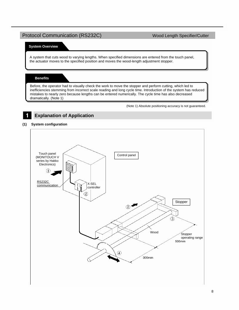
A system that cuts wood to varying lengths. When specified dimensions are entered from the touch panel, the actuator moves to the specified position and moves the wood-length adjustment stopper.
Before, the operator had to visually check the work to move the stopper and perform cutting, which led to inefficiencies stemming from incorrect scale reading and long cycle time. Introduction of the system has reduced mistakes to nearly zero because lengths can be entered numerically. The cycle time has also decreased dramatically. (Note 1)
(Note 1) Absolute positioning accuracy is not guaranteed.
Touch panel (MONITOUCH V series by Hakko
Electronics)
RS232C communication
Stopper operating range
Stopper
Wood
X-SEL controller
Control panel

9
(2) Explanation of operation
Description Example
[1] Enter a wood length from the touch panel. The entered length is transferred to the controller via RS232C communication.
Enter “800” as the length. * The value actually transferred to the
controller is “500” (800 – 300 mm).
[2] The controller moves the slider to the specified position (coordinate).
The slider moves to the coordinate position corresponding to 500 mm.
[3] The stopper attached to the slider moves, causing the target wood to be pressed against the work stopper and set in place.
(800 mm from the stopper to the cutting position)
[4] The wood is securely held and cut. The work is cut to the overall length of 800 mm.
The touch panel and X-SEL controller are connected via RS232C communication. Communication uses the communication program stored in the X-SEL controller, and the program in the touch
panel is used to perform all X-SEL controller operations. (No operation program is required on the X-SEL controller side.)
How to set the X-SEL controller and touch panel comprising this system is explained below.
Communication Settings
The flow of setting RS232C communication between the X-SEL controller and touch panel is specified below.
When a system uses a touch panel, a common practice is to connect the touch panel to a PLC and allow the PLC and X-SEL controller to communicate via PIOs. This is because separate communication parameters and program are needed to communicate with a touch panel. Although every manufacturer provides communication programs for their key PLC products, the user must create a communication program for connecting a touch panel with other devices.
Hakko Electronics’s MONITOUCH V series used in this system comes standard with a built-in communication program with the X-SEL controller. Therefore, it can communicate with the X-SEL controller directly without going through a PLC.
Conditions
Protocol Communication (RS232C)
Set the X-SEL controller Set X-SEL controller parameters. Set the touch panel Set the touch panel parameters and create screens. Connect the devices Connect the X-SEL controller and touch panel using a RS232C communication cable.
Start the system Start the touch panel program to start the system.
Refer to p. 39. Refer to p. 40. Refer to p. 43. Refer to p. 43.
10
(1) Set the X-SEL controller
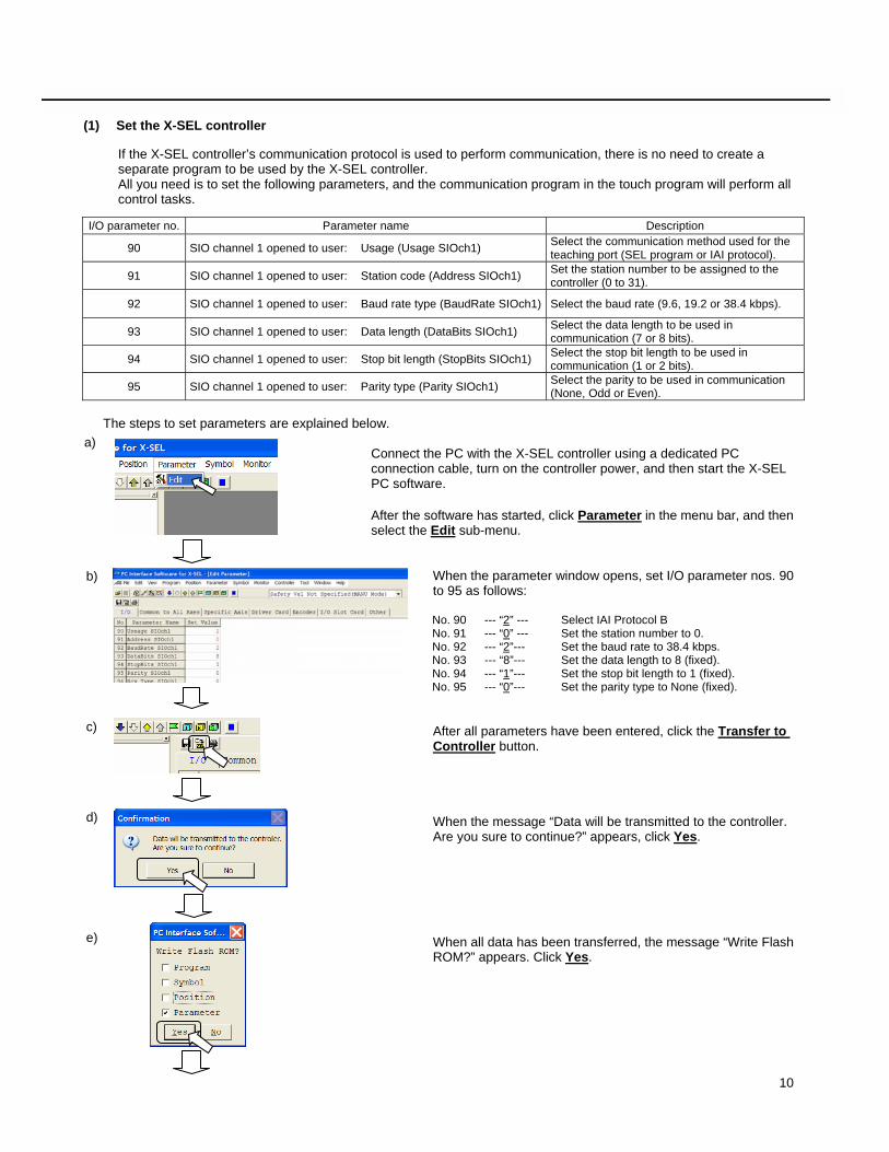
If the X-SEL controller’s communication protocol is used to perform communication, there is no need to create a separate program to be used by the X-SEL controller. All you need is to set the following parameters, and the communication program in the touch program will perform all control tasks.
I/O parameter no. Parameter name Description
90 SIO channel 1 opened to user: Usage (Usage SIOch1) Select the communication method used for the teaching port (SEL program or IAI protocol).
91 SIO channel 1 opened to user: Station code (Address SIOch1) Set the station number to be assigned to the controller (0 to 31).
92 SIO channel 1 opened to user: Baud rate type (BaudRate SIOch1) Select the baud rate (9.6, 19.2 or 38.4 kbps).
93 SIO channel 1 opened to user: Data length (DataBits SIOch1) Select the data length to be used in communication (7 or 8 bits).
94 SIO channel 1 opened to user: Stop bit length (StopBits SIOch1) Select the stop bit length to be used in communication (1 or 2 bits).
95 SIO channel 1 opened to user: Parity type (Parity SIOch1) Select the parity to be used in communication (None, Odd or Even).
The steps to set parameters are explained below.
Connect the PC with the X-SEL controller using a dedicated PC connection cable, turn on the controller power, and then start the X-SEL PC software. After the software has started, click Parameter in the menu bar, and then select the Edit sub-menu.
When the parameter window opens, set I/O parameter nos. 90 to 95 as follows:
No. 90 --- “2” --- Select IAI Protocol B No. 91 --- “0” --- Set the station number to 0. No. 92 --- “2”--- Set the baud rate to 38.4 kbps. No. 93 --- “8”--- Set the data length to 8 (fixed). No. 94 --- “1”--- Set the stop bit length to 1 (fixed). No. 95 --- “0”--- Set the parity type to None (fixed). After all parameters have been entered, click the Transfer to Controller button.
When the message “Data will be transmitted to the controller. Are you sure to continue?” appears, click Yes. When all data has been transferred, the message “Write Flash ROM?” appears. Click Yes.
a)
b) c) d) e)

11
When the message “Restart the controller?” appears, click Yes. This completes the setting of necessary parameters.
(2) Setting the touch panel
For the touch panel, the following tasks are required: [1] Set communication parameters [2] Create screens [3] Transfer the screens and communication parameters to the touch panel
[1] Setting communication parameters
Connect the touch panel with the PC using a dedicated cable, and start the touch-panel image maker/editor software “V-SFT.” From the menu bar, click System Setting, point to Temp. CTRL/PLC2Way Setting, and then select Temp. CTRL/PL 2Way Comm. Setting….
Select the Use Temp. Control Network/PLC2Way Communication checkbox.
Leave all other settings unchanged, and click Refer to modular…. The window shown to the left appears.
Specify the modular jack to be connected to the X-SEL controller (modular jack 2 is used in this example) by selecting Temp./PLC2Way checkbox, and then click OK.
f)
Protocol Communication (RS232C)
a) b) c)
12
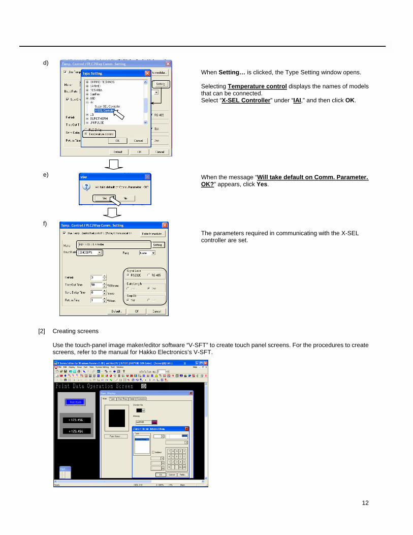
When Setting… is clicked, the Type Setting window opens.
Selecting Temperature control displays the names of models that can be connected. Select “X-SEL Controller” under “IAI,” and then click OK.
When the message “Will take default on Comm. Parameter. OK?” appears, click Yes.
The parameters required in communicating with the X-SEL controller are set.
[2] Creating screens
Use the touch-panel image maker/editor software “V-SFT” to create touch panel screens. For the procedures to create screens, refer to the manual for Hakko Electronics’s V-SFT.
d) e) f)
13
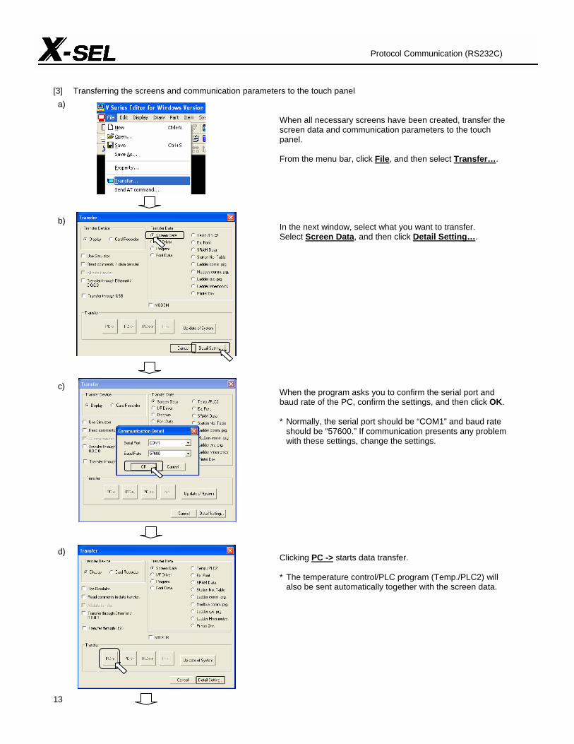
[3] Transferring the screens and communication parameters to the touch panel
When all necessary screens have been created, transfer the screen data and communication parameters to the touch panel.
From the menu bar, click File, and then select Transfer….
In the next window, select what you want to transfer. Select Screen Data, and then click Detail Setting….
When the program asks you to confirm the serial port and baud rate of the PC, confirm the settings, and then click OK. * Normally, the serial port should be “COM1” and baud rate
should be “57600.” If communication presents any problem with these settings, change the settings.
Clicking PC -> starts data transfer.
* The temperature control/PLC program (Temp./PLC2) will also be sent automatically together with the screen data.
Protocol Communication (RS232C)
a) b) c) d)

14
When the window shown to the left closes, all data has been successfully transferred.
(3) Connect the devices
Connect the RS232C communication cable to the X-SEL controller as shown below. Note) Turn off the power before connecting the cable.
(4) Start the system
After connecting the X-SEL controller and touch panel using the RS232C cable, turn on the power to start communication. Press the various buttons and controls set on the touch panel to check the operations.
e)
(*1) After connecting the RS232C cable, set the mode switch on the controller to “MANU.” (*1)
MONITOUCH V series by Hakko
Electronics
TP port V series (MJ1/2) modular connector, 8 pins
* Shielded wire

15
Protocol Communication (RS232C)
16
Free Protocol Communication (RS232C) PC Board Checker
Explanation of Application (1) System configuration
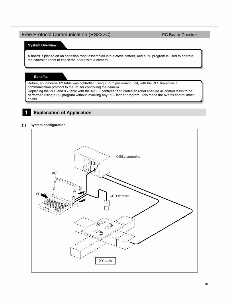
System Overview
A board is placed on an cartesian robot assembled into a cross pattern, and a PC program is used to operate the cartesian robot to check the board with a camera.
Benefits
Before, an in-house XY table was controlled using a PLC positioning unit, with the PLC linked via a communication protocol to the PC for controlling the camera. Replacing the PLC and XY table with the X-SEL controller and cartesian robot enabled all control tasks to be performed using a PC program without involving any PLC ladder program. This made the overall control much easier.
X-SEL controller
PC
CCD camera
XY table
17
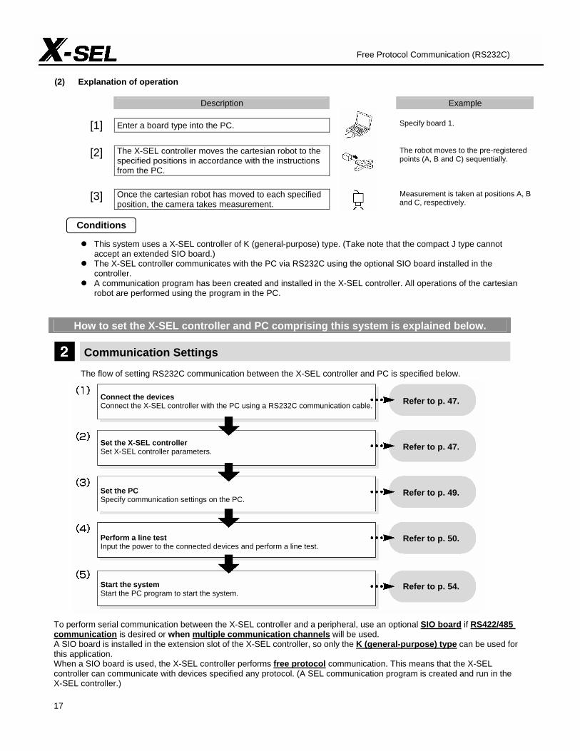
(2) Explanation of operation
Description Example
[1] Enter a board type into the PC. Specify board 1.
[2] The X-SEL controller moves the cartesian robot to the specified positions in accordance with the instructions from the PC.
The robot moves to the pre-registered points (A, B and C) sequentially.
[3] Once the cartesian robot has moved to each specified position, the camera takes measurement.
Measurement is taken at positions A, B and C, respectively.
This system uses a X-SEL controller of K (general-purpose) type. (Take note that the compact J type cannot accept an extended SIO board.)
The X-SEL controller communicates with the PC via RS232C using the optional SIO board installed in the controller.
A communication program has been created and installed in the X-SEL controller. All operations of the cartesian robot are performed using the program in the PC.
How to set the X-SEL controller and PC comprising this system is explained below.
Communication Settings
The flow of setting RS232C communication between the X-SEL controller and PC is specified below.
To perform serial communication between the X-SEL controller and a peripheral, use an optional SIO board if RS422/485 communication is desired or when multiple communication channels will be used. A SIO board is installed in the extension slot of the X-SEL controller, so only the K (general-purpose) type can be used for this application. When a SIO board is used, the X-SEL controller performs free protocol communication. This means that the X-SEL controller can communicate with devices specified any protocol. (A SEL communication program is created and run in the X-SEL controller.)
Conditions
Free Protocol Communication (RS232C)
Connect the devices Connect the X-SEL controller with the PC using a RS232C communication cable. Set the X-SEL controller Set X-SEL controller parameters. Set the PC Specify communication settings on the PC. Perform a line test Input the power to the connected devices and perform a line test. Start the system Start the PC program to start the system.
Refer to p. 47. Refer to p. 47. Refer to p. 49. Refer to p. 50. Refer to p. 54.
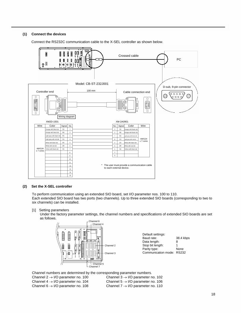
18
(1) Connect the devices
Connect the RS232C communication cable to the X-SEL controller as shown below.
(2) Set the X-SEL controller
To perform communication using an extended SIO board, set I/O parameter nos. 100 to 110. Each extended SIO board has two ports (two channels). Up to three extended SIO boards (corresponding to two to six channels) can be installed.
[1] Setting parameters Under the factory parameter settings, the channel numbers and specifications of extended SIO boards are set
as follows.
Default settings: Baud rate: 38.4 kbps Data length: 8 Stop bit length: 1 Parity type: None Communication mode: RS232
Channel numbers are determined by the corresponding parameter numbers. Channel 2 → I/O parameter no. 100 Channel 3 → I/O parameter no. 102 Channel 4 → I/O parameter no. 104 Channel 5 → I/O parameter no. 106 Channel 6 → I/O parameter no. 108 Channel 7 → I/O parameter no. 110
Channel 6 Channel 4
Channel 2 Channel 3
Channel 5 Channel 7
Crossed cable PC
D-sub, 9-pin connector Model: CB-ST-232J001
100 mm Controller end Cable connection end
Wiring diagram XM2D-1501 XM-2A0901
Wire Color Signal No. No. Signal Color Wire
AWG24 x 7 cores
AWG24 x 7 cores
Orange with black dot SD 1 Orange with black dot RD 2 Light gray with black dot RS 3 Light gray with red dot CS 4 White with black dot ER 5 White with red dot DR 6 Yellow with black dot SG 7
8 9 10 11 12 13 14 15
* The user must provide a communication cable to each external device.
SD Orange with black dot RD Orange with black dot RS Light gray with black dot CS Light gray with red dot ER White with black dot DR White with red dot SG Yellow with black dot
3 2 7 8 4 6 5 1 9

19
[2] Parameter settings Example) When “28100013” is set in I/O parameter no. 100
The specifications of channel 2 are set as follows (the boxed portions indicate the specifications set by this parameter.)
Baud rate: 0: 9.6 kbps, 1: 19.2 kbps, 2: 38.4 kbps, 3: 57.6 kbps, 4: 76.8 kbps, 5: 115.2 kbps
Data length: 7, 8
Stop bit length: 1, 2
Parity type: 0: None, 1: Odd, 2: Even
Communication mode: 0: RS232, 1: RS422, 2: RS485
Half-duplex receive operation type (effective only in RS485 communication) 0: Enable receive after send 1: Do not enable receive after send
Board channel assignment 1: Dsub upper, 2: Dsub lower (See the figure below.)
Extended I/O slot assignment: 3rd from standard I/O (See the figure below.)
1st, 2nd, 3rd from the standard I/O
The steps to set parameters are explained below.
Connect the PC with the X-SEL controller using a dedicated PC connection cable, turn on the controller power, and then start the X-SEL PC software. After the software has started, click Parameter in the menu bar, and then select the Edit sub-menu.
When the parameter window opens, set I/O parameter nos. 100 and 102 as follows:
No. 100 --- “28100013” No. 102 --- “28100023”
* Parameter no. 102 need not be set if channel
3 is not used.
After all parameters have been entered, click the Transfer to Controller button.
Free Protocol Communication (RS232C)
upper
lower
a)
b) c)

20
When the message “Data will be transmitted to the controller. Are you sure to continue?” appears, click Yes. When all data has been transferred, the message “Write Flash ROM?” appears. Click Yes.
When the message “Restart the controller?” appears, click Yes. This completes the necessary settings on the X-SEL controller side.
(3) Setting the PC
In this example, the setting procedure using HyperTerminal that comes with Windows is explained.
Click the Windows Start menu, point to Programs, point to Accessories, point to Communications, and then select HyperTerminal.
When the window shown to the left opens, enter a file name, select an appropriate icon, and then click OK.
d) e) f) a) b)
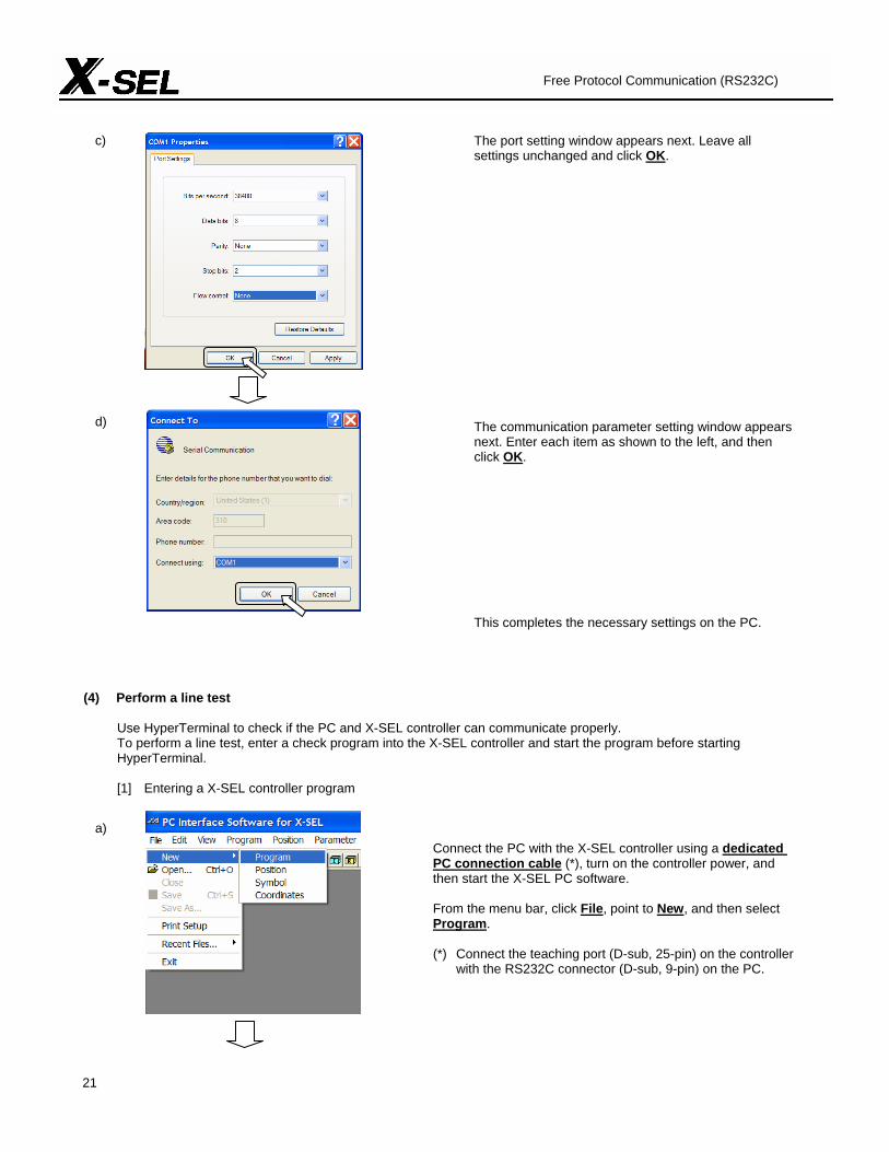
21
The port setting window appears next. Leave all settings unchanged and click OK. The communication parameter setting window appears next. Enter each item as shown to the left, and then click OK. This completes the necessary settings on the PC.
(4) Perform a line test
Use HyperTerminal to check if the PC and X-SEL controller can communicate properly. To perform a line test, enter a check program into the X-SEL controller and start the program before starting HyperTerminal.
[1] Entering a X-SEL controller program
Connect the PC with the X-SEL controller using a dedicated PC connection cable (*), turn on the controller power, and then start the X-SEL PC software. From the menu bar, click File, point to New, and then select Program. (*) Connect the teaching port (D-sub, 25-pin) on the controller
with the RS232C connector (D-sub, 9-pin) on the PC.
Free Protocol Communication (RS232C)
c) d) a)

22
When the program entry window opens, enter a desired program. * In this example, a sample line test program is entered. Refer
to p. 54 for the program details.
When the program has been entered, click the Transfer to Controller button.
In the confirmation window, click Yes.
The next window asks you to select a number to store the program under. Click a desired number, and then click Write. In this example, the program is stored under No. 1.
When the program transfer is finished, the message “Write Flash ROM?” appears. Click Yes. The program has been successfully written to the controller. Now, you can start the program.
b) c) d) e) f)
b) c) d) e) f)
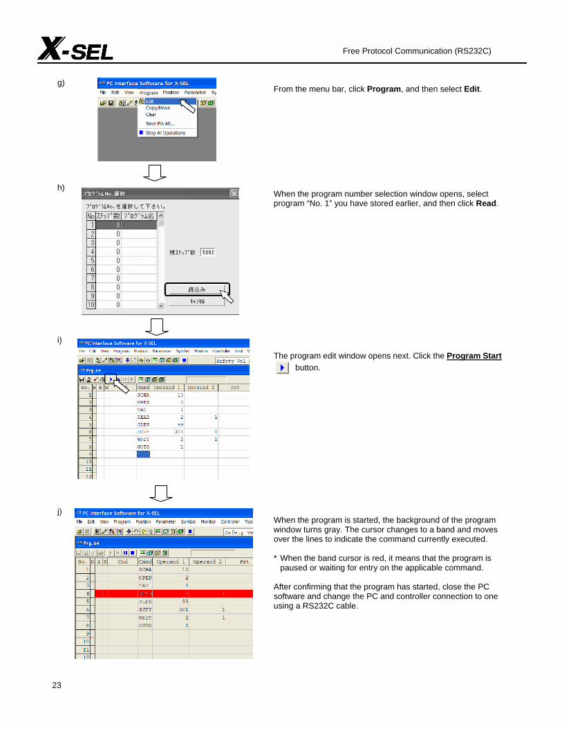
23
From the menu bar, click Program, and then select Edit.
When the program number selection window opens, select program “No. 1” you have stored earlier, and then click Read.
The program edit window opens next. Click the Program Start button.
When the program is started, the background of the program window turns gray. The cursor changes to a band and moves over the lines to indicate the command currently executed. * When the band cursor is red, it means that the program is
paused or waiting for entry on the applicable command. After confirming that the program has started, close the PC software and change the PC and controller connection to one using a RS232C cable.
Free Protocol Communication (RS232C)
g) h) i) j)
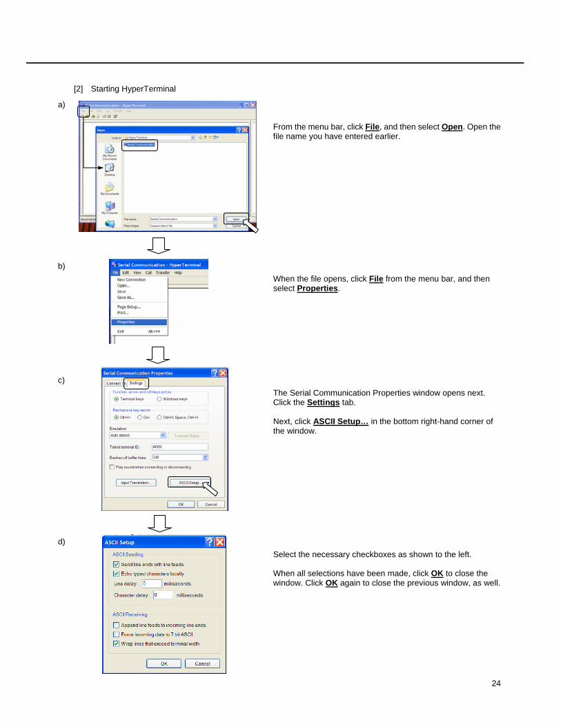
24
[2] Starting HyperTerminal
From the menu bar, click File, and then select Open. Open the file name you have entered earlier.
When the file opens, click File from the menu bar, and then select Properties.
The Serial Communication Properties window opens next. Click the Settings tab. Next, click ASCII Setup… in the bottom right-hand corner of the window.
Select the necessary checkboxes as shown to the left. When all selections have been made, click OK to close the window. Click OK again to close the previous window, as well.
a) b) c) d)
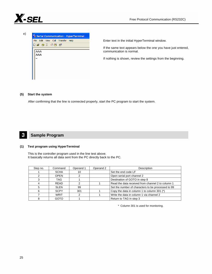
25
Enter text in the initial HyperTerminal window.
If the same text appears below the one you have just entered, communication is normal.
If nothing is shown, review the settings from the beginning.
(5) Start the system
After confirming that the line is connected properly, start the PC program to start the system.
Sample Program (1) Test program using HyperTerminal
This is the controller program used in the line test above. It basically returns all data sent from the PC directly back to the PC.
Step no. Command Operand 1 Operand 2 Description 1 SCHA 10 Set the end code LF 2 OPEN 2 Open serial port channel 2 3 TAG 1 Destination of GOTO in step 8 4 READ 2 1 Read the data received from channel 2 to column 1 5 SLEN 99 Set the number of characters to be processed to 99 6 SCPY 301 1 Copy the data in column 1 to column 301 (*) 7 WRIT 2 1 Write the data in column 1 via channel 2 8 GOTO 1 Return to TAG in step 3
* Column 301 is used for monitoring.
Free Protocol Communication (RS232C)
e)


Catalog No.: CJ0086-1A (August 2005)
www.intelligentactuator.com Website: http://www.intelligentactuator.com E-mail: [email protected] Information contained in this catalog is subject to change without notice for the purpose of product improvement.