industrial electrical engineering and automation. the serial port.pdf · industrial electrical...
TRANSCRIPT

Indu
stria
l Ele
ctric
al E
ngin
eerin
g an
d Au
tom
atio
n
Applied Mechatronics
The Serial Port

Indu
stria
l Ele
ctric
al E
ngin
eerin
g an
d Au
tom
atio
n
Applied Mechatronics
The Serial Port History
• Accessing remote locations before LAN and Internet: Telephone line and modem
• The information has to be transferred in a serial way
• From this scenario we have the terms DTE and DCE
Indu
stria
l Ele
ctric
al E
ngin
eerin
g an
d Au
tom
atio
n
Applied Mechatronics
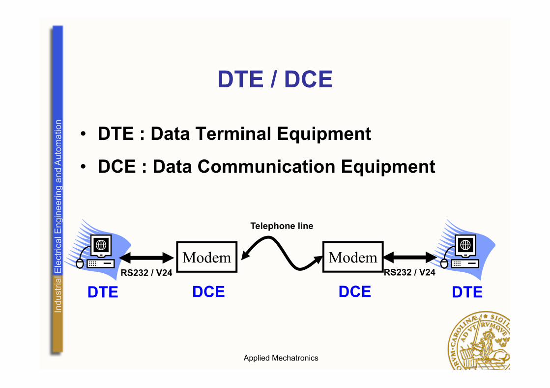
DTE / DCE
• DTE : Data Terminal Equipment
• DCE : Data Communication Equipment
DTE
Modem
DCERS232 / V24
Telephone line
Modem
DCERS232 / V24
DTE

Indu
stria
l Ele
ctric
al E
ngin
eerin
g an
d Au
tom
atio
n
Applied Mechatronics
DTE / DCE continued…
• IBM defined the PC as a DTE
• An input pin on a DCE is an output on a DTE and vice versa
• The signal definitions were made in the Recommended Standard RS232

Indu
stria
l Ele
ctric
al E
ngin
eerin
g an
d Au
tom
atio
n
Applied Mechatronics
RS-232• Standardized by EIA/TIA EIA-232 or later
TIA-232 with a following letter for the version (in the 60’s…)
• Initially for teletypewriters, but the use was soon extended to printers and other peripherals
• Great confusion in the usage over the years (and still…)

Indu
stria
l Ele
ctric
al E
ngin
eerin
g an
d Au
tom
atio
n
Applied Mechatronics
RS-232C
• Defines a 25 pole D-sub connector
• About 20 signals for communication and synchronization
• Actual communication uses 3 pins – TxD (transmitt data) DTE out
– RxD (receive data) DCE out
– SG (signal ground) -

Indu
stria
l Ele
ctric
al E
ngin
eerin
g an
d Au
tom
atio
n
Applied Mechatronics
RS-232C continued…
• Handshaking pins e.g.– RTS (request to send) DTE out
– CTS (clear to send) DCE out
– DSR (data set ready) DCE out
– DCD (data carrier detect) DCE out
– DTR (data terminal ready) DTE out

Indu
stria
l Ele
ctric
al E
ngin
eerin
g an
d Au
tom
atio
n
Applied Mechatronics
RS-232C signals
• Voltage
• Bipolar signals1 is -3..-25 V
0 is +3..+25 V

Indu
stria
l Ele
ctric
al E
ngin
eerin
g an
d Au
tom
atio
n
Applied Mechatronics
Connecting DTE/DCE
• A DTE is connected to a DCE pin to pin
• DTEs are most common today
• A DTE can connect to another DTE using a “null modem cable”
• In this cable the wires are crossed so that input meets the corresponding output.

Indu
stria
l Ele
ctric
al E
ngin
eerin
g an
d Au
tom
atio
n
Applied Mechatronics
The serial port on the PC
• In the beginning the full 25-pole RS232C was used
• Later the 9-pole version was defined EIA/TIA-574
• Low voltage definitions EIA/TIA-562

Indu
stria
l Ele
ctric
al E
ngin
eerin
g an
d Au
tom
atio
n
Applied Mechatronics
Why Use this Dinosaur?
• USB is intended to replace but -• Implementing USB is a huge task• Serial port relies on simple definitions and
is easy to use both on the software and hardware sides
• Encapsulated chip-solutions for using USB exist but use the serial port definitions on both sides

Indu
stria
l Ele
ctric
al E
ngin
eerin
g an
d Au
tom
atio
n
Applied Mechatronics
The asynchronous serial format
1 0 1 0 0 0 1 1
1
idlestart
parity stop
LSB MSB
Logical levels shown

Indu
stria
l Ele
ctric
al E
ngin
eerin
g an
d Au
tom
atio
n
Applied Mechatronics
About the asynchronous format
• Character oriented (maximum 8 bits)
• Agreement on the speed (bits/s)
• Standardized Baud rates
• Synchronization for each character/byte
• A UART (Universal Asynchronous Receiver Transmitter)handles the conversion to/from serial format

Indu
stria
l Ele
ctric
al E
ngin
eerin
g an
d Au
tom
atio
n
Applied Mechatronics
Handshaking
• Receiver may be choked by too much data
• Hardware pins can be used e.g. RTS-CTS
• XON/XOFF characters can be used if only characters are transmitted

Indu
stria
l Ele
ctric
al E
ngin
eerin
g an
d Au
tom
atio
n
Applied Mechatronics
American Standard code for Information Interchange