example 4 - scada pro · pdf file3.5 non linear analysis (pushover) ... the pushover analysis...
TRANSCRIPT

Example 4 Assessment and redesign according to EC8part3

«ASSESSMENT AND REDESIGN»

«ASSESSMENT AND REDESIGN ACCORDING TO EC8 part3»
Contents
I. PREFACE 5 II. SCADA PRO 5
CONDITIONS ...................... 6
INTRODUCTION ................. 6
III. GENERAL DESCRIPTION 7
Geometry .......................... 7
Materials ........................... 7
Design Regulations ............ 7
Assumptions about loads - analysis 7
1st STEP
1.1 Creation of a new case study 9
1.2 Modelling 9
1.3 Slabs - Loads 9
1.4 Analysis 9
1.5 Design 10
1.6 Interaction curves and surfaces 12
1.6.1 Calculation of the structural members’ resistance (Pushover) 12
1.6.2 Detailing 13
1.6.3 Calculation of the interaction curves/surfaces Μ-Ν 14
2nd STEP
2.1 Preface 24
2.2 Introduction 24
2.3 Preliminary analysis 25
3rd STEP
3.1 Nonlinear Analysis Scenarios 29
3.2 Run scenarios 29
3.3 Nonlinear Analysis (PUSHOVER) Combinations 35
3.4 Nonlinear Analysis (PUSHOVER) Results 36
3.4.1 Capacity Curve ....... 39

«ASSESSMENT AND REDESIGN ACCORDING TO EC8 part3»
4
3.4.2 Idealized Capacity Curve 39
3.4.3 Target Displacement 40
3.4.4 Representation of the structure 41
3.5 Non Linear Analysis (PUSHOVER) Checks 44
3.6 Seismic Force 47
4thSTEP
4.1 Columns-walls reinforcement 50
4.1.1 Rehabilitation of columns-walls 50
4.1.2 Concrete jacket for columns-walls 52
4.1.3 FRPs – laminates of columns-walls 58
4.1.4 Protection of columns-walls 62
4.2 Beams reinforcement 64
4.2.1 Additional concrete layers – Concrete jackets 66
4.2.2 Steel laminates – FRPs 70
«ASSESSMENT AND REDESIGN ACCORDING TO EC8 part3»
5
I. PREFACE
The analysis methods applied for the assessment and the seismic redesign of existing reinforced concrete structures are the elastic methods; static or dynamic, as well as the inelastic methods (material nonlinearity); static or dynamic.
The elastic methods are based on the linear relationship between stresses and deformations for the structural elements, while the nonlinear behavior of the structure is taken into consideration through approximate methods (e.g. global behavior factor q or local ductility factors m). The elastic analysis methods is simpler in implementation, however are less accurate compared to the inelastic analysis methods.
On the other hand, the inelastic analysis methods contribute to a better supervision and assessment of the structural behavior of the structure, by identifying not only the failure mechanisms but also the progressive failure. So, the deformation of the structural members and their remaining overstrength can be checked, as well as the structural ductility of the structure. So, the nonlinear analyses lead to a more reliable and safe structure. The nonlinear dynamic analysis (meaning the time-history analysis with direct integration of the nonlinear equations of motion) is the most reliable analysis method of structures.
In the nonlinear analysis the seismic action is described by real seismic records or artificial accelerograms of peak ground acceleration [1]. However, the simulation of the cyclic post-elastic behavior of the structural members is under research and experimental verification. Also, the accelerograms used for the analysis must be selected as appropriate in order to represent the seismicity of the region in a reliable way.
Consequently, the engineer that conducts the assessment and the redesign of an existing structure applying nonlinear dynamic analysis must be experienced. Since the nonlinear analysis is complex and computationally time consuming, especially for 3D multi-storey structures (notice that since that method is nonlinear, the mode superposition principles is not applicable), the nonlinear dynamic analysis is not a method of general use.
Instead, the nonlinear static analysis leads to results that are less reliable that the one of the nonlinear dynamic analysis, but more representative about the nonlinear behavior of the structure, that cannot be considered with accuracy, when linear methods are applied. In case that an incremental later load is applied of a certain pattern until collapse, the nonlinear static method is considered as Pushover analysis. The Pushover analysis is not as complex as the nonlinear dynamic analysis.
The nonlinear static analysis is not a modern analysis method. However the last decades, the researchers developed structural models that can simulate the nonlinear behavior of the critical regions of the RC structural members. This is the reason why the nonlinear analysis is so widely applicable for the assessment and the redesign of the existing structures.
II. SCADA PRO

«ASSESSMENT AND REDESIGN ACCORDING TO EC8 part3»
6
SCADA Pro incorporates the nonlinear static analysis. Considering the default parameters, all demanding nonlinear static analyses are applied, as well as, all the appropriate design checks are performed for each performance objective according to EC8 part 3 and the corresponding results are presented with a direct and supervisory way.
The nonlinear static analysis provides information and supervision of the order of occurrence of the plastic hinges in the critical regions of the structural members. The engineer can study the gradually deformed shape of the structure step by step and so can easily detect the weak regions or under failure regions of the structure.
That method is used for the assessment of the structural behavior and the comparison of the capacity of the existing structures with the structural demand defined in the selected performance objective, according to EC8 part 3. This method can also be applied for the redesign of existing structures or for the calculation of the ratio au/ai according to EC8 for new structures. This ratio is calculated through the capacity curve and it is used for the definition of the behavior factor q.
CONDITIONS
Important precondition for applied the nonlinear analysis scenario is the existence of steel reinforcement in the structural members. The steel reinforcement is calculated, when the structural members are designed ONLY according to Eurocode 2, considering the materials of steel and concrete with modified strength. The modified concrete and steel material correspond to the type of the old materials of the existing structure. The materials that will be used to approach the properties of the existing materials should NOT be type Β or STI (old type of materials) but the properties of the new materials should be modifies with the corresponding safety factors as appropriate.
INTRODUCTION
The user manual contains guidelines for the application of a nonlinear analysis with SCADA Pro.
The test case presented in the current manual is a three storey reinforced concrete (RC) frame structure, considered as existing structure. The main objective is the assessment and the redesign of the structure according to the selected performance objective. The presentation of this test case is the guide for a new user to become familiar with the software SCADA Pro.

«ASSESSMENT AND REDESIGN ACCORDING TO EC8 part3»
7
III. GENERAL DESCRIPTION
Geometry The reinforced concrete (RC) building examined is a three storey frame structure with basement. The foundation is composed by strip foundation and a single footing under the stair core.
Materials
The material of the structural elements is reinforced concrete of type C20/25 with steel of type B500C for the steel reinforcement. In case the type of materials of the existing structure is Β and STI (old type of material), then they will not be used with their strength values considered, but they will be adjusted to the strength values of the new type of materials modified with the corresponding safety factors.
Design Regulations
Eurocode 8 for the seismic loads considered. Eurocode 2 for the structural design. Code of Structural Interventions (KAN.EPE.2013) for the retrofit of the structural elements.
Assumptions about loads - analysis
- Dynamic Response Spectrum analysis method
The load cases according to this analysis method are the following: (1) G (permanent) (2) Q (imposed) (3) EX (seismic loads in Χ direction derived from dynamic analysis). (4) ΕZ (seismic loads in Z direction derived from dynamic analysis).

«ASSESSMENT AND REDESIGN ACCORDING TO EC8 part3»
8
(5) Erx ± (torsional moments derived from the seismic loads imposed with an accidental eccentricity versus the nominal location of the mass of the storey ±2eτzi). (6) Erz ± (torsional moments derived from the seismic loads imposed with an accidental eccentricity versus the nominal location of the mass of the storey ±2eτxi). (7) EY (vertical seismic load in Y direction derived from dynamic analysis). - Nonlinear static analysis (Pushover analysis)
The structure is subjected to an incremental later load of a certain pattern until collapse.

«ASSESSMENT AND REDESIGN ACCORDING TO EC8 part3»
9
1. st STEP: PRELIMINARY PROCEDURE
The input data of an existing structure are inserted with the same procedure as for a new designed structure. The analytical description about the drawing, the analysis and design of a RC structure is presented in the manual entitled “Case study: Reinforced Concrete Structure”.
The main steps preceded the Pushover analysis are presented summarily:
1.1 Creation of a new case study
1.2 Modelling
Insertion of the structural elements in the interface by using the appropriate tools (dxf/dwg, templates, draft, modelling).
1.3 Slabs - Loads
Insertion of slabs and loads, using the corresponding tools.
1.4 Analysis
A preliminary analysis of the structure must be applied according to Eurocode 8 (static or dynamic EC8 scenario).

«ASSESSMENT AND REDESIGN ACCORDING TO EC8 part3»
10
1.5 Design
As it was aforementioned, important prerequisite for the implementation of the nonlinear analysis scenario is the existence of the steel reinforcement, which is calculated only when the cross-sections are designed according to Eurocode 2 considering the modified strength value of the materials.
As the materials of the existing structure are considered the modern materials with modified properties with respect to the corresponding safety factors. The materials of the existing structure are not type of Β and STI (old type of materials).
If the structure studied has materials of type B and STI, then for the definition of the materials in the design parameters field and before the preliminary design, use the properties of the modern materials modified with the safety factors according to EC8 part3.
The values of the compressive strength Fck of the concrete και the yield strength Fyk for the steel are the characteristic values.
According to the Code of Structural Interventions (KAN.EPE.2013), the strength value are experimentally defined median values of fcm and fym for concrete and steel, respectively.
Especially for the existing materials when the design checks are in terms of deformation the characteristic values are equal to the median values (Fck=fcm and Fyk=fym). So, in the above fields you will type the corresponding values for concrete and steel for beams and columns.
As it was aforementioned, the Code gives in tables the values of partial safety factors γm (γcu and γsu) for the existing materials and the design checks in terms of deformation.

«ASSESSMENT AND REDESIGN ACCORDING TO EC8 part3»
11
EXAMPLE:
Assume that the existing structure’s construction materials are Β160 and STI with median strength values: Concrete -> fcm=11,0 MPa Steel -> fym=250,0 MPa
Since the design checks are in terms of forces, then: fk=fm-s and fd=fk/γm
In the corresponding fields considering sufficient data reliability level, type: -Concrete s=0.10fcm -> fck=fcm-0.1fcm=0.90fcm Reliability level -> γc=1.65 so fcd=0.9x11.5/1.65=6.27 Mpa -Steel s=0.15fym -> fyk=fym-0.15fym=0.85fym Reliability level -> γs=1.25 so fyd=0.85x270/1.25=183.6 Mpa
In the “Fck” and “Fyk” fields type the calculated FINAL VALUES (Resulting after dividing withthe safety factors) and the corresponding fields of the safety factors γcu and γsu type one.
Since the design checks are in terms of deformation, then: fk=fm and fd=fk/γm
- Concrete Reliability level -> γc=1.20 so fcd=11.5/1.20=9.58 Mpa - Steel Reliability level -> γs=1.20 so fyd=270/1.20=183.6 Mpa
In the “Fck” and “Fyk” fields type the calculated FINAL VALUES (Resulting after dividing withthe safety factors) and the corresponding fields of the safety factors γcu, γcs, γsu and γss type one.
Then continue with the preliminary design and the final step is the adjustment of the existing steel reinforcement to the calculated one on the preliminary design by using the column’s and beam’s detailing.
Until that step the synoptic procedure is the same followed for the assessment and design of a new RC structure.

«ASSESSMENT AND REDESIGN ACCORDING TO EC8 part3»
12
1.6 Interaction curves and surfaces
1.6.1 Calculation of the structural members’ resistance (Pushover)
Since the preliminary design has been completed and the existing steel reinforcement had been inserted in the structural model and before the creation of the pushover analysis scenario, it is demanding to precede the “Strength calculation (Pushover)” by selecting the corresponding command: Ribbon: “Member Design”>“Columns”>“Results”>“Strength Calculation (Pushover)” Through this command, the program calculates the interaction diagrams between bending moment (M) and axial force (N) for all columns of the structure in all levels.
Select the Strength Calculation (Pushover) of the columns and the walls per level or for the total structure. The program calculates automatically the interaction surfaces N-Mx-Mz of the columns/walls which are displayed directly on the screen. NOTES:
In the valuation step, and after reinforcement adapted to existing, for the beams, the calculation of the interaction curves N-M is not necessary, because concerns uniaxial bending and the differences are very small.
If however, you want the exact calculation of the moments of resistance of the beams, then into the reinforcement detailing of each beam in corresponding field, select the calculation of Ultimate Moment Resistant pressing "Initial".

«ASSESSMENT AND REDESIGN ACCORDING TO EC8 part3»
13
1.6.2 Detailing
The command “Detailing” opens a new tool with multiple features about modifying the column’s steel reinforcement (the analytical description is in the user manual of SCADA Pro), presenting the internal forces diagrams and the corresponding values and deformations, as well as the interaction curves N-M and the interaction surfaces N-Mx-Mz.

«ASSESSMENT AND REDESIGN ACCORDING TO EC8 part3»
14
For the interaction curves/surfaces click the following button .
1.6.3 Calculation of the interaction curves/surfaces Μ-Ν
It is about the calculation and the display of the interaction surface of the axial load and the ultimate bending moment. It depends on the geometry of the cross-section, the material and the steel reinforcement. It is a 3D surface and represents the envelope of the ultimate biaxial bending resistance and the axial load (Μy, Mz, N). Also, the strain-stress relationship diagrams are displayed for the steel, concrete as well as the moment – curvature diagram of the cross-section.
CALCULATION OF THE INTERACTION SURFACE For the generation of the interaction surface of the selected cross-section, select the buttons “Calc1” or “Calc2”. The difference between the two diagrams refers to the part with negative values (-Ν) that represents the tension.
-Calc1: This command generates the linear diagram of tension, which means lower resistance in tension less favorable conditions -Calc2: This command calculates the median values of tension with result in the curved form and more reliable results about the tension. Notice: The upper part of the diagram (Compression) is not affected from the previous selection. Both calculation methods (“Calc1” and “Calc2”) generate the same diagrams under compression.

«ASSESSMENT AND REDESIGN ACCORDING TO EC8 part3»
15
For the graphical display of the horizontal cutting planes of bending moments considering a consistent value of axial load N, activate the checkbox “Horizontal”.
GRAFICAL DISPLAY
For the 2D display, select the corresponding buttons :

«ASSESSMENT AND REDESIGN ACCORDING TO EC8 part3»
16
Select the buttons in order to display the diagram that is derived by reducing and increasing the scale of the axial load’s display.

«ASSESSMENT AND REDESIGN ACCORDING TO EC8 part3»
17
HORIZONTAL BAR OF MAXIMUM VALUES
In the horizontal bar you see the six maximum values that are derived from the 3D interaction surface.
These values represent the maximum (+) and minimum (-) value of each internal force and they are the pick values of the surface. NOTE: The axes system of the bending moments coincides with the local axes system of the column, if you haven’t modified the calculated angle beta for each column when the mathematical model is created. The discontinuous line represents the negative values.

«ASSESSMENT AND REDESIGN ACCORDING TO EC8 part3»
18
FIND POINTS ON THE SURFACE
This field has multiple uses:
For the display of the horizontal cutting planes
Type in the field “Step” a value and click the following buttons .
With a single click a horizontal the perimeter of a horizontal plane is displayed (a curve colored magenta). The points of the curve are pairs of ultimate bending moments in both main direction of the cross-section (Mx, Mz) for a single value of the axial load (N=constant) and multiple values of the rotation angle of the neutral axis. The field “Step” represents the step in which the axial load axis is run for the display of the corresponding horizontal curves (horizontal cutting planes). By selecting Ν+, the horizontal curves for the positive values of the axial load are displayed and by selecting Ν- for the negative values. Furthermore, for each horizaontal curve, the maximum and minimum values of the bending moments Μy and Mz are listed for the corresponding specific value of the axial load N.

«ASSESSMENT AND REDESIGN ACCORDING TO EC8 part3»
19
For the calculation of the ultimate biaxial bending resistance for specific values of the internal forces Ν-Μy-Mz given.
Type the values of the internal forces in the corresponding fields Ν, Μy, Mz and click the
following button . Then the program calculates and displays the following graph:
- The point with coordinates (Ν, My, Mz) is located on the diagram - The line that connect the start of the axes (0, 0, 0) with the point (Ν, My, Mz) is drawn (a line colored orange). - The curve Ν* is drawn and the corresponding Μy,max and Mz,max are calculated.
- The ultimate biaxial bending resistance (RMy, RMz) is calculated for the corresponding internal forces (Ν,My,Mz). These are the red dots on the horizontal curve.
- The moment-curvature diagram is drawn.
The moment-curvature diagram is defined for the specific value of the angle of the neutral axis.

«ASSESSMENT AND REDESIGN ACCORDING TO EC8 part3»
20
If you type in the field “Angle” , and angle with value different from 0,90,180,270 degrees, the part of the diagram with negative values of bending moment will be displayed, too.
POINTS PROJECTION ON THE INTERACTION SURFACE
NOTE: Insert the values of the internal forces in the corresponding fields and click the following button
. The program locates the point with the corresponding coordinates and draws the line (orange line) that connects that point with the start of the axes (0, 0, 0). Then, the program projects the line to intersect the interaction surface (cyan color) and record the corresponding values of the
biaxial bending moment resistance of the intersection point (useful values in the Pushover analysis).

«ASSESSMENT AND REDESIGN ACCORDING TO EC8 part3»
21
3D DISPLAY OF THE INTERACTION SURFACE
Activate the checkbox “3D” and select the internal force from the drop-down list for the display with colored display. If you select Μy the surface is colored along the axis Y. The color gradation define the spacing of the cutting planes according to the colored bar on the right. The horizontal bar on the bottom of the screen records the maximum and minimum values of the internal forces.

«ASSESSMENT AND REDESIGN ACCORDING TO EC8 part3»
22
The colored interaction surfaces gradually for the internal forces Μz and Ν, respectively.

«ASSESSMENT AND REDESIGN ACCORDING TO EC8 part3»
23
Select “Νο” to display more analytic interaction surface, without color gradation.
Keep pressing the left click of the mouse and while you move it the interaction surface rotates respectively.

«ASSESSMENT AND REDESIGN ACCORDING TO EC8 part3»
24
2nd STEP : PRELIMINARY CHECK
2.1 Preface
In the section where you create the analysis scenarios, when you select “EC8_General”, the following types of analysis scenarios appear:
The types:
Static
Dynamic
That types of analysis are used for the analysis of new structures according to EC8 and the
national annexes.
All the rest types:
Nonlinear
Linear Static
Linear Dynamic
Preliminary Static
Preliminary Dynamic
They are used for the assessment and the redesign of the existing structures according to the Code of Structural Interventions (KAN.EPE.2013) provisions.
2.2 Introduction
The types of analysis scenarios “Preliminary Static” and “Preliminary Dynamic” are two preliminary analysis that are applied in order to check, if the conditions for the application of linear analysis (static or dynamic), for the assessment and redesign of the structure, are fulfilled. More specifically, the insufficiency index “λ” are calculated that indicate the resistance of the structure under seismic loads.. It is also examined the in-plan and in elevation regularity of the structure. The provisions of the Code of Structural Interventions (KAN.EPE.2013) sets specific conditions for the application of static or dynamic analysis.

«ASSESSMENT AND REDESIGN ACCORDING TO EC8 part3»
25
For the elastic static analysis provides a set of criteria (among other morphological and regularity), that have been implemented in the program and are presented in the form of checks; only the criteria that contain quantifiable variables and could be implemented computationally. For the elastic dynamic analysis the only criterion is the insufficiency index «λ» to be less than or equal to 2.5.
However, for both methods, the elastic methods can be applied for assessment purposes only, if the permanent loads are increase 15% (γSd = 0.15). So in the Ribbon “Analysis” you can define a preliminary scenario analysis either static or dynamic, which will be executed with the elastic response spectrum and all checks will be performed on the selection of the analysis, based on what has been mentioned above.
Necessary condition for applying a preliminary analysis scenario is the existence of steel reinforcement and the calculation of the biaxial bending moment resistance.
2.3 Preliminary analysis
In the Ribbon “Analysis” select the command “New Scenario”.
You create a new scenario “Preliminary Static” or “Preliminary Dynamic”.
For this analysis scenario the stiffness of the structural elements are defined according EC8
Then, you follow the process for applying an analysis scenario.

«ASSESSMENT AND REDESIGN ACCORDING TO EC8 part3»
26
In the dialog box “Parameters” define the parameters like in the analysis scenarios of EC8:
The response spectrum for the preliminary checks must be elastic.
In the above dialog box there is added a new button “KAN.EPE.” , which opens a new dialog box presented above:

«ASSESSMENT AND REDESIGN ACCORDING TO EC8 part3»
27
In this dialog box you can define the following two parameters (like in the nonlinear analysis scenario):
The Data Reliability Level
The Damage Level for the definition of the coefficient γSd.
The value 0 in the following field means that the coefficient will take values. In case you want to set a different value, you type it and the calculation are implemented by taking into consideration your own value.
The following fields are inactive because refer to the scenarios of elastic and dynamic analysis, that will be explained later.
Especially, for the preliminary check, the selection of the calculation method of the shear length Ls does not affect the results.
Then, you perform the analysis scenario, then you save the file with the load combinations and in the section “Checks” the results of the checks that correspond to criteria of the appropriate analysis application are presented.
The check about the symmetric distribution of the mass and the stiffness.
The check about the percentage of the shear force against which the wall structural system resists.
The check of the interstorey drift of storeys or nodes. The first check refers to the interstorey drift between storeys (underlying and overlying floor) and the nodes’ interstorey drift refers to the displacement of each node of the storey. Both checks are implemented in each direction.
The check about the fundamental periods.
The checks about the insufficiency indices and the morphological regularity . The check of the insufficient index λ is implemented per storey for the beams and the columns separately. It is recorded the number of the beams where the index λ is lower or greater to 2.5 per strorey, as well as the percentage of the total beams and columns. The totals in the bottom are the summations per elements and in total. Finally, the check of morphological regularity contains the criterion of the median insufficiency index λki per storey.
If for example the insufficiency index λ is greater than 4.0 for the 30% of the structural elements, the further assessment of the structure is not necessary.
The nonlinear analysis (Pushover) or the elastic analysis (static or dynamic) are applied with respect to the previous criteria.

«ASSESSMENT AND REDESIGN ACCORDING TO EC8 part3»
28
3. rd STEP: NONLINEAR ANALYSIS
Since the interaction surface of all structural elements are calculated, the model is ready for performing Pushover analysis. Initially, go back to Ribbon “Analysis” and create a nonlinear analysis scenario.
For Greece, select the scenario “EC-8 Greek/Nonlinear” as well as the corresponding scenarios for Cyprus, Italy and Austria, for which the National Annexes are incorporated in SCADA Pro.
EC8_General is a scenario that doesn’t contains a National Annex. This means that the user has to update the coefficients according the Annex of his country.
Using the scenarios EC8_Greek, EC8_Italy, EC8_Cyprus and EC8_Austrian all the corresponding coefficients are filled in the corresponding fields automatically.
Especially, for the nonlinear static analysis scenario (EC-8_Greek / EC-8_Nonlinear), when EC8 provisions are considered, the multipliers of the inertial properties that will be defined in this step of the procedure, will be taken into consideration in the initial Pushover analysis where only the permanent and imposed loads are active. The default values of the loads are defined in EC8.
Then, about the parameters of the nonlinear analysis, you choose if they will be kept the same as in the first pushover analysis or they will be reduced step by step with reference to the initial value. The reduction can take place either in the beginning of analysis step or after the formulation of the plastic hinge.

«ASSESSMENT AND REDESIGN ACCORDING TO EC8 part3»
29
3.1 Nonlinear Analysis Scenarios
Select the new scenarios “EC8_General Dynamic” and define the “Properties”:
3.2 Run scenarios
Initialize Data

«ASSESSMENT AND REDESIGN ACCORDING TO EC8 part3»
30
Parameters
In the dialog box of Pushover Analysis Parameters, the parameters outside the borders are defined as for a linear analysis. In that case the Response Spectrum must be Elastic. In “Levels ΧΖ” section:
Select the lowest and the highest level where the seismic actions will be imposed for the analysis’ purposes.
It is recommended to define as the highest level the last complete level (no stairwell termination). This level contains the Check Node which is the diaphragm node or another node, in the same level but in the outer perimeter of the building.
The activation of the following checkbox means that the elements that belong in levels under the reference level, are taken into consideration as potential locations of plastic hinges.
In “Seismic Combinations” section:

«ASSESSMENT AND REDESIGN ACCORDING TO EC8 part3»
31
Check the load combinations considered in the pushover analysis. Each combination implies
the application of one seismic force in one direction (X or Z direction) and one seismic force
in the corresponding transverse direction multiplied by a factor, defined in
. The coefficient k is given as 0.3 by default.
Check the seismic forces’ distribution along height (Triangular or/and Orthogonal).
Check if you want to consider the accidental Eccentricities due to
which moments are developed in x or/and z direction.
The check means that the base shear is calculated from
the dynamic analysis.
Activate all seismic combinations with the accidental eccentricities considered and then 64 load combinations are produced. That means that 64 pushover analyses are conducted and consequently the computational time is increased significantly.
In the last section:
On "Active Infill Masonry" choose whether we want to be fully taken into account in analysis the Masonry Infill included in our construction.
Active “Check of 2nd order effects” to consider the 2nd order effects when is necessary.
In “Check Node”, type the number of the node for calculation of the Capacity Curve. This is the diaphragm node or another node in the outer perimeter of the last complete level of the building.
In “Number of Steps”, define the maximum number of steps (analyses) for each Pushover analysis. Pushover is an iterative analysis procedure that terminates when the structure collapses; when the sequence of the developed plastic hinges evolves a collapse mechanism.

«ASSESSMENT AND REDESIGN ACCORDING TO EC8 part3»
32
The “Number of Steps” is an upper limit, in order to avoid an extraordinary number of analysis steps needed until the structural collapse. Steps default value is 200.
“Maximum displacement” in percentage (%) of the total height of the building is another way of setting an upper limit in the analysis steps. The Pushover iterative process ends when the displacement of the “Check Node” versus the height of the structure gets over the specified percentage. By default the maximum displacement’s upper value is 3% of the total height of the building.
“Lamda Range (%)” is about λ load factor. In each step and for each element, the λ factor is calculated. In the element with the minimum λ, a plastic hinge will be created. The default value 0: the program considers only the minimum λ value, which means that in each step only one element is considered for the formation of a plastic hinge, even if there are elements with λ values very close to that. The setting a different value (i.e. λmin=10%): This means the elements with values of λ between λmin and 10% + λmin will be considered in this step with plastic hinges in the corresponding edge (element node).
Suppose that, on the first step of the pushover, minimum λ value is 1.0 and corresponds to a certain element with a plastic hinge. Defining 10% Lamda Range, all elements with λ between 1.0 and 1.1 will develop plastic hinges together in the same step.
The options about the definition of the “Constant value of the Shear Length Ls” are the following:
The shear length Ls is calculated as a fixed value based on the length of each element in all
steps of the analysis
Otherwise, the shear length is calculated on each step, based on the internal forces resulting,
with Shear Length = Μ/V in the end section of the element, i.e. the distance of the end
section from the point of zero moments.
“Effective Stiffness” is about the calculation of the elements’ stiffness. On the first step of the nonlinear analysis calculated the internal forces due to dead and live
loads and the stiffness considered on the elements, are multiplied by the factors set in
during scenario’s creation. On the second step of the nonlinear analysis considering the seismic loads, you have more than one options for the stiffness calculation: - Initial: the stiffness remains the same as in the first step and invariable during the analysis procedure - Step by step calculation: the stiffness is calculated in each step, whether plastic hinge are created or not. Stiffness is decreased, compared to the original value. - After plastic hinge development: the stiffness is calculated as previously, with the difference that the value is decreased since the first plastic hinge has been developed. Until that step of analysis the initial value of the effective stiffness is considered.
“Data reliability”, is the Knowledge Level. Select between Limited, Normal and Full. The aspects that affect the definition of the knowledge levels are: geometry, details, material. The knowledge level influences the partial safety factors.

«ASSESSMENT AND REDESIGN ACCORDING TO EC8 part3»
33
a. Partial Safety Factors
Based on the knowledge level achieved through the different levels of survey, inspection and testing, the following set of partial safety factors (PSF) as shown in Table 3.3 are used in the verifications.
Table 3.3: Partial safety factors (PSF) used for verification, according to the different knowledge levels (KL).
PSF
KNOWLEDGE LEVEL Material Overstrength
KL1 1.20 (γm) 1.20 ( γRd , γov)
KL2 γm as in EN1998-1 γRd , γov as in EN1998-1
KL3 0.80 (γm) 0.80 ( γRd , γov)
EXAMPLE: In the dialog box “Spectra” is defined the response spectrum which indicates the structural demand of the structure. The structural demand in combination with a limit state (LS) composes a performance objective. In the dialog box: Three limit states are considered for the structural design of the structure. The states of damage related to the limit states considered are presented below:
-LS of near collapse (NC) -LS of significant damage (SD) -LS of damage limitation (DL)
National Authorities define the appropriate performance level, which means they propose a performance level (limit state) against a seismic event. They usually propose more than one performance level (a combination of a limit state with a seismic event). The seismic events or hazard levels (HL) are described with a return period and a peak ground acceleration. The peak ground acceleration and the incidence of the seismic events are characteristic of the seismicity of the region. The return periods established by the National Authorities are usually the following:
The suggested values for the return periods of Eurocode are:
- HL with return period 2475 years, corresponding to a probability of exceedance 2% in 50 years. - HL with return period 475 years, corresponding to a probability of exceedance 10% in 50 years. - HL with return period 225 years, corresponding to a probability of exceedance 20% in 50 years.
Selecting one of the three default commands , the dialog box is filled in automaticaly, with the values of the spectra parameters related to a specific limit state , thus the performance objectives proposed by the Eurocodes are depicted in the dialog box.

«ASSESSMENT AND REDESIGN ACCORDING TO EC8 part3»
34
Use National Appendix to define the appropriate performance levels; the structural capacity (limit state) related to the seismic demand (hazard level).
Press OK to save the Parameters and close the dialog box.
Automatic Procedure
Then select and the program will conduct the analysis and the corresponding calculations, automatically:
«ASSESSMENT AND REDESIGN ACCORDING TO EC8 part3»
35
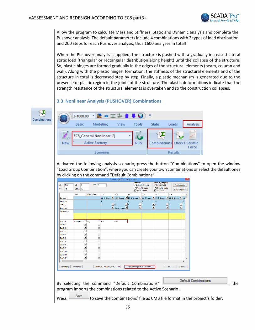
Allow the program to calculate Mass and Stiffness, Static and Dynamic analysis and complete the Pushover analysis. The default parameters include 4 combinations with 2 types of load distribution and 200 steps for each Pushover analysis, thus 1600 analyses in total!
When the Pushover analysis is applied, the structure is pushed with a gradually increased lateral static load (triangular or rectangular distribution along height) until the collapse of the structure. So, plastic hinges are formed gradually in the edges of the structural elements (beam, column and wall). Along with the plastic hinges’ formation, the stiffness of the structural elements and of the structure in total is decreased step by step. Finally, a plastic mechanism is generated due to the presence of plastic region in the joints of the structure. The plastic deformations indicate that the strength resistance of the structural elements is overtaken and so the construction collapses.
3.3 Nonlinear Analysis (PUSHOVER) Combinations
Activated the following analysis scenario, press the button “Combinations” to open the window “Load Group Combination”, where you can create your own combinations or select the default ones by clicking on the command “Default Combinations”.
By selecting the command “Default Combinations” , the program imports the combinations related to the Active Scenario .
Press to save the combinations’ file as CMB file format in the project’s folder.

«ASSESSMENT AND REDESIGN ACCORDING TO EC8 part3»
36
You will need this file for checks applied for the retrofitting methods.
3.4 Nonlinear Analysis (PUSHOVER) Results
In Pushover analysis, the structure is subjected to monotonically increasing lateral forces (uniform or triangular distribution) that represent the seismic inertia forces until collapse. Plastic hinges are developed gradually at the edges of the structural elements (beams, columns, walls). The plastic hinges lead to the reduction of the stiffness at the start and end length of the structural elements, gradually. The analysis is completed, when a failure mechanism is developed based on the formed plastic hinges in the structural elements. The corresponding structural elements cannot receive further tension due to the excessive plastic deformations developed and the structure is led to failure.
The user can see both the pushover analysis results in the form of a capacity curve that correspond to a specific load combination and the deformed shape in each point of the capacity curve (analysis steps):
-Select the three dimensional view of the structure -Select one of the commands in the ribbon “Analysis” and in the command group “View”
On the interface, the three dimensional undeformed and deformed shape of the structure is displayed and the dialog box “Report” appears.

«ASSESSMENT AND REDESIGN ACCORDING TO EC8 part3»
37
In the field “Check Node” define the serial number of the node that will be used for the derivation of the capacity curve.
The check node is usually master node of the rigid diaphragm in the top floor of the structure. If a diaphragm doesn’t exist, select a node in the perimeter of the top floor.
You can select a different check node in order to see the corresponding results, without perform again the pushover analysis. The corresponding results are updated automatically.
In this example the Check Node is the one with the label “63”.
In the top of the window select one of the distributions set previously
and a load combination .
The list contains the steps of the selected nonlinear analysis.

«ASSESSMENT AND REDESIGN ACCORDING TO EC8 part3»
38
Each step provides the corresponding shear value Vb(kN) and the λ load factor, while at the same time are presented are presented in the corresponding graph the following data:
Capacity Curve
Idealized Capacity Curve
Target Displacement

«ASSESSMENT AND REDESIGN ACCORDING TO EC8 part3»
39
3.4.1 Capacity Curve
The capacity curve represents the nonlinear relationship between the base-shear force and the displacement of the control (Check) node.
The points depicted on the capacity curve are the “Steps” of the pushover analysis. The selected step is displayed with pink color and represents the time of a plastic hinge creation.
In the following field you can change the check node and derive the results for a different check node, without repeating the analysis. The presentation of the results is updated automatically. 3.4.2 Idealized Capacity Curve It is the linearized capacity curve according to the procedure given in Annex B of EN 1998-1. The idealized elasto-plastic force- displacement relationship is calculated.

«ASSESSMENT AND REDESIGN ACCORDING TO EC8 part3»
40
3.4.3 Target Displacement The target displacement of the check node, for the tree different Limit States, is determined according to the Displacement Coefficient Method given in Annex B of EN 1998-1.

«ASSESSMENT AND REDESIGN ACCORDING TO EC8 part3»
41
Spectrum: is like the Spectrum command explained in the section about the scenarios parameters. Note that these parameters are considered in the calculation of the target displacement related to the seismic demand and not to the structural capacity. For that reason these parameters are irrelevant with the capacity curve and so they can be defined or modified before or after the implementation of the analysis procedure.
In Parameter select the method for the derivation of the capacity curve (“Idealization Method”) between the two methods proposed in Annex B of EN 1998-1.
Activate and the program uses the Iterative Procedure proposed in EC8 for the calculation of the target displacement.
3.4.4 Representation of the structure
The deformed shape of the structure is depicted in real time and the location of the plastic hinges formed in the edges of the structural elements for each step. There are two methods:
1. Select the step from the list
and you will see the corresponding deformed shape of the structure in the selected step and the location of the plastic hinges. The undeformed shape of the structure is displayed together with the deformed one, in gray and in red color respectively. Colored dots indicate the edges with the plastic hinges and the different colors the damage levels.

«ASSESSMENT AND REDESIGN ACCORDING TO EC8 part3»
42
According to the chord rotation of the plastic hinges, dots have three different colors:
- Blue color, when the chord rotation is less than the (θum – θy)/2γRd value. - Yellow color, when the chord rotation is between the (θum – θy)/2γRd and (θum - θy) values. - Red color, when the cord rotation is more than the (θum – θy) value.
2. Otherwise, select the first step and press to see the structure’s motion and the plastic
hinges’ formation. Press to stop it. You can have the same effect by clicking on a “step” in the list and turning the mouse wheel.
, , and buttons gives you the deformed shape of the structure for the three Limit States. That means that the structure is displayed on the step, where the deformation of the control node is equal to the corresponding target displacement.
The colored points on the curve correspond to the three LS:
: blue
: yellow
: red

«ASSESSMENT AND REDESIGN ACCORDING TO EC8 part3»
43
«ASSESSMENT AND REDESIGN ACCORDING TO EC8 part3»
44
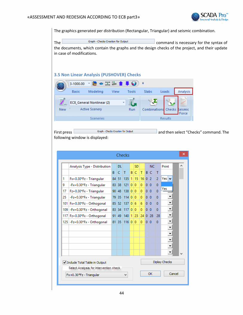
The graphics generated per distribution (Rectangular, Triangular) and seismic combination.
The command is necessary for the syntax of the documents, which contain the graphs and the design checks of the project, and their update in case of modifications.
3.5 Non Linear Analysis (PUSHOVER) Checks
First press and then select “Checks” command. The following window is displayed:

«ASSESSMENT AND REDESIGN ACCORDING TO EC8 part3»
45
A table with the total number of beams (B) and columns (C) which have lower capacity than the demanded, for each pushover and each LS. “T” means total.
Indicate with YES the pushover analysis to include in the printout or just check
to consider all of them.
The button opens the TXT file that contains all members’ capacity in terms of deformation for the pushover analysis a “YES” indicator in the “Print” column:

«ASSESSMENT AND REDESIGN ACCORDING TO EC8 part3»
46
Checks document help you to assess in which Pushover analysis, the structural elements present lower capacity than the one defined in the considered LS. It means that it can be easily observed in which Pushover analysis, the defined performance level is not satisfied. In that case the structure must be modified, for example through the reinforcement of some structural elements and be redesigned. First decide the analysis, which indicates the redesign of the existing structure by selecting one from the list.
The Interventions procedure is explained on “Members Design” chapter. In the bottom of the text file, the Shear resistance check appears only for the structural members under shear failure.

«ASSESSMENT AND REDESIGN ACCORDING TO EC8 part3»
47
3.6 Seismic Force
Activated the nonlinear analysis scenario and then press “Seismic Force”. In the TXT file, first the load case data are presented, then, the spectrum parameters, the performance level and the damage level. Then, for each analysis, the maximum base shear, the corresponding maximum displacement, the overstrength ratio and the minimum overstrength ratios presented in each direction.
«ASSESSMENT AND REDESIGN ACCORDING TO EC8 part3»
48
4 th STEP: RETROFITTING METHODS
A structural member need to be reinforced when it can not carry the vertical loads and the loads resulting from the design earthquake. The need for reinforcement of the concrete structural elements is determined based on the options:
Performance objective
Load distribution along height of the horizontal / seismic loads considered in the design checks of the retrofitting methods.
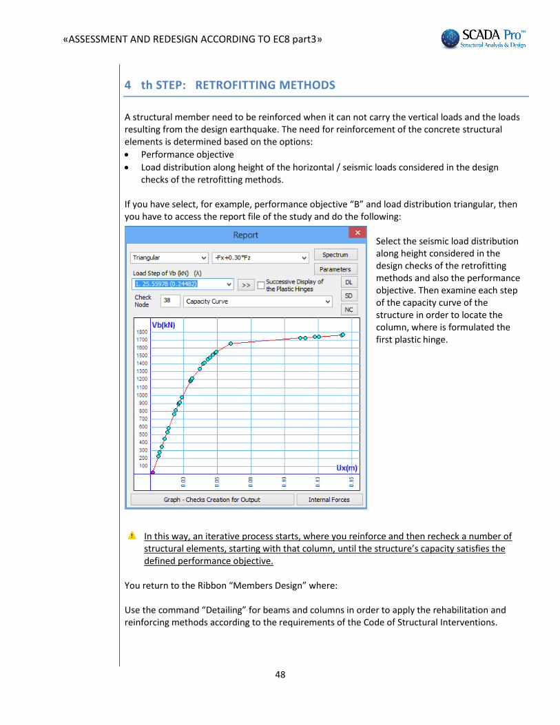
If you have select, for example, performance objective “B” and load distribution triangular, then you have to access the report file of the study and do the following:
Select the seismic load distribution along height considered in the design checks of the retrofitting methods and also the performance objective. Then examine each step of the capacity curve of the structure in order to locate the column, where is formulated the first plastic hinge.
In this way, an iterative process starts, where you reinforce and then recheck a number of
structural elements, starting with that column, until the structure’s capacity satisfies the defined performance objective.
You return to the Ribbon “Members Design” where: Use the command “Detailing” for beams and columns in order to apply the rehabilitation and reinforcing methods according to the requirements of the Code of Structural Interventions.

«ASSESSMENT AND REDESIGN ACCORDING TO EC8 part3»
49
Important prerequisite for the design of the retrofitting methods is the calculation of the load combinations of the nonlinear static analysis saved in the corresponding step of the analysis/design procedure.

«ASSESSMENT AND REDESIGN ACCORDING TO EC8 part3»
50
4.1 Columns-walls reinforcement
4.1.1 Rehabilitation of columns-walls
The section “Rehabilitation” contains tools for the rehabilitation of the columns according to the Code of Structural Interventions (KAN.EPE.2013).
The user can select one of the three rehabilitation methods by activating the corresponding
checkbox. Then, select the command “Add” and the rehabilitation methods will be included in the final report. Select the command “Delete”, the rehabilitation methods are excluded from the report.
Furthermore, in SCADA Pro, the techniques and the material considered in each rehabilitation method are enriched with the corresponding material and techniques of the company Sika A.E
. The user has direct access in the library of Sika materials by pressing the button , which appear in the dialog boxes about the beam reinforcement.
Select the command “Sika” , and then select the appropriate material for each
rehabilitation method. Also, select the following button and a PDF file is downloaded automatically with an analytical description of the material properties as well as information of its use.

«ASSESSMENT AND REDESIGN ACCORDING TO EC8 part3»
51
«ASSESSMENT AND REDESIGN ACCORDING TO EC8 part3»
52
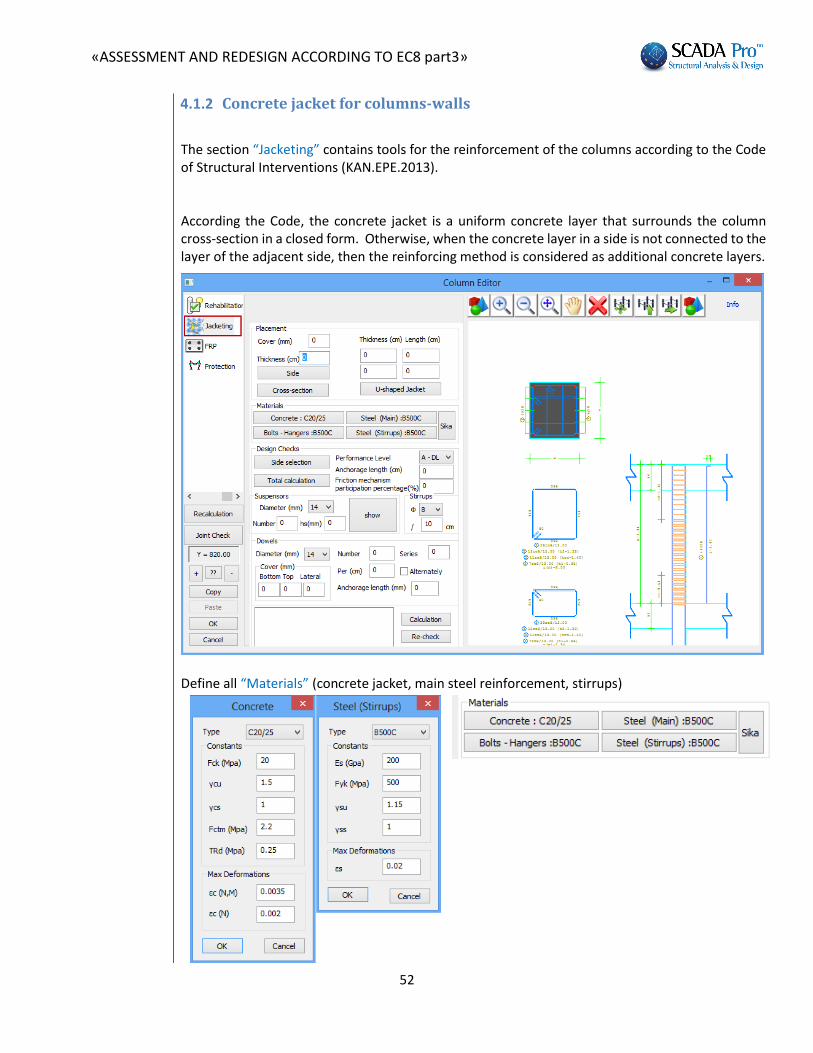
4.1.2 Concrete jacket for columns-walls
The section “Jacketing” contains tools for the reinforcement of the columns according to the Code of Structural Interventions (ΚΑΝ.ΕPΕ.2013). According the Code, the concrete jacket is a uniform concrete layer that surrounds the column cross-section in a closed form. Otherwise, when the concrete layer in a side is not connected to the layer of the adjacent side, then the reinforcing method is considered as additional concrete layers.
Define all “Materials” (concrete jacket, main steel reinforcement, stirrups)

«ASSESSMENT AND REDESIGN ACCORDING TO EC8 part3»
53
Furthermore, in SCADA Pro, the techniques and the material considered in each rehabilitation method are enriched with the corresponding material and techniques of the company Sika A.E.
The user has direct access in the library of Sika materials by pressing the button , which appear in the dialog boxes about the beam reinforcement.
Select the command “Sika” , and then select the appropriate material for each
rehabilitation method. Also, select the following button and a PDF file is downloaded automatically with an analytical description of the material properties as well as information of its use.
1. Define the “Cover” and “Thickness” of the concrete layer and apply either on the total cross-
section as a jacket or on a side by clicking the button “Side” and then selecting with the mouse the corresponding side. In this way, you can define different thickness per side. Therefore, the cover is common in all sides of the cross-sections.
The minimum “Thickness” of the jacket is modified with reference to the type of concrete (standard, gunite, special concrete).
When the thickness per side defers, then you select the command “Side” and pick with the mouse the corresponding side. If the thickness is the same in the total cross-section, you select the button “Total cross-section”.
Furthermore, there is the option to insert U-shaped Jacket, typing the respective Thickness and Length.

«ASSESSMENT AND REDESIGN ACCORDING TO EC8 part3»
54
2. Insert the steel reinforcement of the jacket with the commands “Main Reinforcement” and “Stirrups” from the list (Chapter A “Column’s Detailing”).
3. Calculate the new interaction surface of the reinforced cross-section by selecting the
following button .
4. Return to the command “Jacket” for the calculation of the dowels.
5. In the field “Stirrups” give the dimeter and the spacing of the stirrups of the
jacket.

«ASSESSMENT AND REDESIGN ACCORDING TO EC8 part3»
55
6. Select the appropriate “Performance level”; Damage Limitation-DL (Immediate Occupancy), Significant Damage-SD (Life Safety), Near Collapse-NC (Collapse Prevention).
7. The compressive force Fcm of the jacket is safely transferred as a shear force along the interface through the three following mechanisms:
- friction
- welded suspensors
- dowels which are activated within an available assemblage length “uo”. The shear resistance along the interface is calculated considering the friction, welded suspensors and dowels mechanisms. In SCADA Pro the critical mechanism for the transfer of the compressive force is the dowels. The friction and the welded suspensors are option and the user decide if they will be taken into consideration in the calculation of the shear resistance along the interface. For the welded suspensors define the diameter, the number and the spacing hs between the new and the existing main steel reinforcement.
For the friction mechanism you have to define one of the following parameters:
- The assemblage length and then the program calculate the resistance considering the friction coefficient μ=1.0.
- The percentage (%) of the compressive force that will be transferred through the friction mechanism.
In case that the friction and the welded suspensors mechanisms are not taken into consideration, the total compressive force is transferred through the dowels.
8. In the field “Dowels” define the diameter and then the program calculate the number and the
spacing of the dowels, as well as the cover in the top, bottom and in both sides:
«ASSESSMENT AND REDESIGN ACCORDING TO EC8 part3»
56
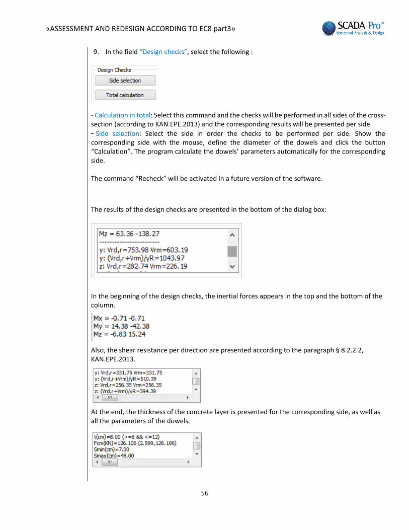
9. In the field “Design checks”, select the following :
- Calculation in total: Select this command and the checks will be performed in all sides of the cross-section (according to KAN.EPE.2013) and the corresponding results will be presented per side.
- Side selection: Select the side in order the checks to be performed per side. Show the corresponding side with the mouse, define the diameter of the dowels and click the button “Calculation”. The program calculate the dowels’ parameters automatically for the corresponding side. The command “Recheck” will be activated in a future version of the software.
The results of the design checks are presented in the bottom of the dialog box:
In the beginning of the design checks, the inertial forces appears in the top and the bottom of the column.
Also, the shear resistance per direction are presented according to the paragraph § 8.2.2.2, ΚΑΝ.ΕPΕ.2013.
At the end, the thickness of the concrete layer is presented for the corresponding side, as well as all the parameters of the dowels.

«ASSESSMENT AND REDESIGN ACCORDING TO EC8 part3»
57
The program calculates the appropriate number of dowels by comparing the number of dowels based on the value of the compression force and the minimum number of dowels based on the jacket’s area and keeps the greater.
In the previous example the minimum number of dowels is 13, while the calculated one is 18, so which is the final number of dowels.
Finally, select the command “Report” to add the design checks’ results in the corresponding chapter of the report.
The command “Recheck” will be activated in the future version fo the software.
The analytical printout of the results is defined in the ribbon “Add-ons” in the command “Calculations’ Printout”.
Select the section “Retrofitting methods” and then select a level or levels and the corresponding results of the design checks as well as the calculated number of dowels per level will be recorded.

«ASSESSMENT AND REDESIGN ACCORDING TO EC8 part3»
58
4.1.3 FRPs – laminates of columns-walls
The steel laminates or the fiber reinforcing polymers (FRPs) is a reinforcing method that results to the increase of the bending resistance and the application of confinement reinforcement. The laminates in general are used as additional tensile reinforcement due to the inadequate existing steel reinforcement. The laminates strengthen the tension zone against flexural failure.
According to the paragraph §8.2.1.3, KAN.EPE.2013, a reinforced concrete cross-section can be strengthened in bending with steel laminates or FRP fabrics. This reinforcing method is applied mainly in beams and slabs and rarely in columns, because it is not allowed to be applied in regions under compression. As an exception, it can be applied in regions under compression when that regions resist against other type of failures, e.g. local buckling resistance of the rebars by applying confinement.
1. Select the reinforcing method; Steel Laminates or FRPs (Fiber reinforced polymers)

«ASSESSMENT AND REDESIGN ACCORDING TO EC8 part3»
59
2. Select the Material.
Furthermore, in SCADA Pro, the techniques and the material considered in each retrofitting method are enriched with the corresponding material and techniques of the company Sika A.E
. The user has direct access in the library of Sika materials by pressing the button , which appear in the dialog boxes about the beam reinforcement..
Select the command “Sika” , and then select the appropriate material for each
rehabilitation method. Also, select the following button and a PDF file is downloaded automatically with an analytical description of the material properties as well as information of its use.
3. Select the Performance Level and the Accessibility level
4. In the field Placement, select:
Default: This command is used in order the length of the column and the width of the laminate to be filled in automatically. The width of the laminate is equal to the width of the corresponding side of the column by default.

«ASSESSMENT AND REDESIGN ACCORDING TO EC8 part3»
60
Afterwards, you set the value of the thickness and the length of the laminate in the corresponding fields with two ways:
1. For each side: Select the button “Side” and show with the mouse the corresponding side of the column.
2. For the total cross-section: Select the button “Cross-section”.
The command “Default” sets the data of all sides of the column. If you want to import laminates in all sides with the same thickness, you enter, at first, the thickness and the anchorage length. Then, click the button “Cross-section”.
If you want afterwards to change the thickness of the laminates of the cross-section in total, set a new value for the thickness and press the button “Default” without pressing again the button “Total cross-section”. The existing laminates change considering the new thickness value.
Side data: This command is used in order to show the number of the side selected with the mouse and also the data of the reinforcing method applied in the corresponding side.
Layers: In this field set the number of the layers.
The placement of the laminates can be uniform or in strips; continuous or discontinuous with intermediate spacing.
Activate the “Continuous Formulation” in the field “Strips’ data” and define the width of the laminate. For considering the discontinuous formulation, deactivate the previous checkbox and define the spacing between the strips.
Activate the checkbox “No participation in bending” and the laminate in the corresponding side will not participate in the bending resistance of the reinforced cross-section.
By selecting the command “Design checks”, the program calculates and presents the minimum thickness t1 and t2 per side, in the checks’ results with respect to the cross-section of the laminate and the type of the material. Then, the thickness t1 and t2 are calculated again with reference to the

«ASSESSMENT AND REDESIGN ACCORDING TO EC8 part3»
61
minimum values of t1 and t2 and the design checks have to be repeated. Since the calculation of the thickness t1 and t2 is an iterative method, select the button “Automatic calculation of the thickness”.
Then the program calculates automatically the final minimum thickness t2, which is presented in the window in the bottom of the dialog box. Then, you have to set this calculated value in the corresponding field and repeat the final design checks.
The structural adequacy of the laminate or the FRP is reached with the increase of the thickness or the number of the layers.
In the section of the results of the design checks are presented first the bending resistance checks of the cross-section and the shear resistance check by direction X or Z according to the paragraph § 8.2.1.3 (a), KAN.EPE.2013.
Furthermore the results are presented by side and the value of the parameter ΔΜ; the difference between the design bending moment and the moment resistance of the initial cross-section, is calculated. If the parameter ΔΜ is positive (the initial cross-section should be reinforced) the thickness values t1 and t2 are calculated as described above. The thickness is defined by the user. SIDE : 1
In the previous example, the thickness t is less than the appropriate t1 και t2. So the thickness t must be equal to 0.7. If you preserve the thickness value t=0.4 then should be used 2 layers. The corresponding results are presented below:
SIDE : 1
So, if you use two layers, then a minimum thickness t=0.35 is needed.
If ΔΜ=0, then there is no need for reinforcement, so t1=t2=0.
Finally, the shear resistance check is presented according to § 8.2.2.2 (iii) ΚΑΝ.ΕPΕ.
Select the command “Printout” to add the results in the corresponding chapter of the report of the study:

«ASSESSMENT AND REDESIGN ACCORDING TO EC8 part3»
62
4.1.4 Protection of columns-walls
The section “Protection” contains the tools for the application of protection methods in columns according to KAN.EPE.2013.
The user can select one of the three rehabilitation methods by activating the corresponding
checkbox. Then, select the command “Add” and the rehabilitation methods will be included in the final report.
Furthermore, in SCADA Pro, the techniques and the material considered in each retrofitting
method are enriched with the corresponding material and techniques of the company Sika A.E
. The user has direct access in the library of Sika materials by pressing the button , which appear in the dialog boxes about the beam reinforcement.
Select the command “Sika” , and then select the appropriate material for each
rehabilitation method. Also, select the following button and a PDF file is downloaded automatically with an analytical description of the material properties as well as information of its use.
IMPORTANT NOTE: The reinforced parts of the columns and walls are pointed out on the screen:
1. In plan view: The node is colored yellow 2. In 3D view: The structural element is colored yellow.

«ASSESSMENT AND REDESIGN ACCORDING TO EC8 part3»
63
Also, according to the type of the reinforcing method, an indicative letter appears of the reinforcing method:
Concrete Jacket: “J” Laminate : “L” FRP: “F”
Prerequisite for the appearance of the label is that you have first selected the button “Report” in the dialog box of the corresponding beam reinforcing method.

«ASSESSMENT AND REDESIGN ACCORDING TO EC8 part3»
64
4.2 Beams reinforcement
The section “Retrofitting methods” contains the tool for the seismic reinforcement and rehabilitation of the beams according to the Greek Code of Structural Interventions (KAN.EPE.). First the calculated steel reinforcement is adjusted to the existing one, then you proceed with the definition of the structural reinforcing techniques. Select the span graphically or by left click on the span in the cad interface. Otherwise, set the
number of the span in the field “Number of Span” . In the “Beams editor”, the beam is depicted in the direction at the input step. In order to locate quickly the beam of interest among the rest structural elements, it is suggested, the numbering and the local axes of all beams to be displayed and then, the corresponding beam to be selected by setting its serial number in the editor utility. In order to define the left and right support of the beam, use the direction of the local axis xx’. The start and the end of the beam element in the editor’s interface is defined with reference to the local axis xx’ direction, without considering the beam’s orientation in the plan view.
«ASSESSMENT AND REDESIGN ACCORDING TO EC8 part3»
65
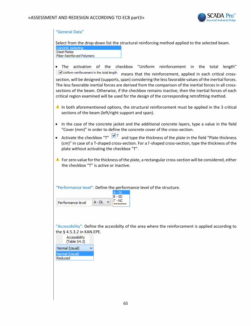
“General Data” Select from the drop-down list the structural reinforcing method applied to the selected beam.
The activation of the checkbox “Uniform reinforcement in the total length”
means that the reinforcement, applied in each critical cross-section, will be designed (supports, span) considering the less favorable values of the inertial forces. The less favorable inertial forces are derived from the comparison of the inertial forces in all cross-sections of the beam. Otherwise, if the checkbox remains inactive, then the inertial forces of each critical region examined will be used for the design of the corresponding retrofitting method.
In both aforementioned options, the structural reinforcement must be applied in the 3 critical sections of the beam (left/right support and span).
In the case of the concrete jacket and the additional concrete layers, type a value in the field “Cover (mm)” in order to define the concrete cover of the cross-section.
Activate the checkbox “T” and type the thickness of the plate in the field “Plate thickness (cm)” in case of a T-shaped cross-section. For a Γ-shaped cross-section, type the thickness of the plate without activating the checkbox “T”.
For zero value for the thickness of the plate, a rectangular cross-section will be considered, either
the checkbox “T” is active or inactive.
“Performance level”: Define the performance level of the structure.
“Accessibility”: Define the accesibilty of the area where the reinforcement is applied according to the § 4.5.3.2 in KAN.EPE.

«ASSESSMENT AND REDESIGN ACCORDING TO EC8 part3»
66
4.2.1 Additional concrete layers – Concrete jackets
“Materials”: Select the type of material for each structural component of the reinforcing method.
“Input Data”: Define the input data of the concrete jacket in the two supports and the span of the beam.

«ASSESSMENT AND REDESIGN ACCORDING TO EC8 part3»
67
In the dialog box “Beam structural reinforcement” that appears, you put the concrete jacket per side (top, bottom, left side, right side). There is also a preview window part of the dialog box where the settings are depicted. The calculations and the design checks of the beam are the same with the checks of the column presented in Chapter A. In order to be taken into consideration the existing side rebars in the calculation of the ultimate moment resistance of the cross-section, you activate the following checkbox:
In order to be taken into consideration the existing additional steel reinforcement in the supports of the beam, in the calculation of the ultimate moment resistance of the cross-section, you activate the following checkbox:
If you activate the following checkbox then, the field “Right Side” is deactivated and receive the same input parameters as they are defined in the field “Left Side”. NOTICE: If you select the button “Default”, then, the corresponding length of the supports and the span are defined automatically. The support’s length is the critical length and the span’s length is the total length of the beam minus the critical of the two supports. The calculated lengths correspond to the reinforcing length.
In the field “Ultimate Moments Resistance”, if you select the button “Initial” or “Reinforced”, then the ultimate bending resistance is calculated of the existing or he reinforced cross-
section, respectively. In the field “Dowels - Suspensors” you define the input parameters of the dowels or the suspensors; diameter and anchorage length.
In the field “Stirrups” set the diameter and the spacing of the stirrups of the concrete jacket.

«ASSESSMENT AND REDESIGN ACCORDING TO EC8 part3»
68
Input parameters in the fields “Top” and “Bottom” If you activate the checkbox “Not considered in the bending resistance check”, then the corresponding concrete jacket or the additional concrete layer are not taken into consideration in the calculation process of the reinforced cross-section. In the first line of the input parameters of the steel reinforcement, you define the number of the rebars of the first/basic rebars’ layer and their diameter. For more than one layers of rebars, you define in the second line, the number of the rebar layers, the diameter of the rebars and the spacing d1 between the rebar layers. The rebar layers have always two rebars.
The activation of the checkbox, on the right of the diameter’s drop-down list , means that the corresponding steel reinforcement is not taken into account in the calculation of the ultimate moment resistance. Input parameters in the fields “Left Side” and “Right Side”
In the field “Rebars” you define the diameter of the corner rebars of the corresponding side, as well as, the number and the diameter of the intermediate rebars. The rest parameters are the same with the parameters of the top and bottom of the cross-section.
In the field “Ultimate Moment Resistance” select the button “Initial” of “Reinforced”. Then, a new dialog box opens, where the interaction diagram of the uniaxial bending moment and the axial force is depicted for the existing and the reinforced cross-section, respectively.

«ASSESSMENT AND REDESIGN ACCORDING TO EC8 part3»
69
Select the command “Design checks” and the program performs all design checks for the concrete jacket in all reinforced sides with concrete jacket (according to the Code of structural interventions) and so the appropriate number of dowels is calculated. Those design checks and their corresponding results are similar to those considered for the columns. The results of the design checks are presented on the bottom of the window. Finally, select the command “Report” and the results of the design checks will be added in the corresponding chapter of the Report.
After any modification on the parameters of the concrete jacket, select the command “Report”, so that the repost to be updated with the new data as appropriate.

«ASSESSMENT AND REDESIGN ACCORDING TO EC8 part3»
70
4.2.2 Steel laminates – FRPs
For these two retrofitting methods, the sane procedure is followed as previously. For the steel laminates or FRPs, select the corresponding layer from the drop-down list.
“Material”: Select the type of the steel for the laminates and the fiber reinforced polymers.
The performance objective and the accessibility level are defined following the same procedure as for the definition of the concrete jacket. “Input data”: Set the input data for the “Steel Laminates” or the “FRPs” for the supports and the sap of the beam.

«ASSESSMENT AND REDESIGN ACCORDING TO EC8 part3»
71
In the dialog box “Beam Reinforcement” that appears, the input data per side of the cross-section (top, bottom, left side, right side) are defined. There is also a window in the dialog box, where the results of the design checks are summarized. The calculations and the design checks of the beam are the same with the checks of the column presented in Chapter A. In order to be taken into consideration the existing side rebars in the calculation of the ultimate moment resistance of the cross-section, you activate the following checkbox:
In order to be taken into consideration the existing additional steel reinforcement in the supports of the beam, in the calculation of the ultimate moment resistance of the cross-section, you activate the following checkbox:
If you activate the following checkbox then, the field “Right Side” is deactivated and receive the same input parameters as they are defined in the field “Left Side”. If you select the button “Default”, then, the corresponding length of the supports and the span are defined automatically. The support’s length is the critical length and the span’s length is the total length of the beam minus the critical of the two supports. The calculated lengths correspond to the reinforcing length.
In the field “Ultimate Moments Resistance”, if you select the button “Initial” or “Reinforced”, then the ultimate bending resistance is calculated of the existing or he reinforced cross-section, respectively.

«ASSESSMENT AND REDESIGN ACCORDING TO EC8 part3»
72
Input parameters in the fields “Top” and “Bottom”
If you activate the checkbox “Not considered in the bending resistance check”, then the corresponding concrete jacket or the additional concrete layer are not taken into consideration in the calculation process of the reinforced cross-section. For the length of the laminate is defined as the length for the concrete jacket. The width of the laminate is defined at first equal to the width of the corresponding side. The definition of the anchorage length is mandatory and the program at first sets a value by default, which can be modified by the user. The number of the layers is the number of the layers of the reinforcement. Input parameters in the fields “Left Side” and “Right Side”
The definition of the reinforcement’s geometry is defined with similar way to the one placed on the top and the bottom of the cross-section. The checkbox about the non-consideration of the laminates of the left and right side in the bending resistance of the cross-section is already activated, because they reinforce the cross-section mainly against shear failure. The placement of the laminates can be uniform or in strips; continuous or discontinuous with intermediate spacing. Activate the “Continuous Formulation” in the field “Strips’ data” and define the width of the laminate. For considering the discontinuous formulation, deactivate the previous checkbox and define the spacing between the strips.

«ASSESSMENT AND REDESIGN ACCORDING TO EC8 part3»
73
By selecting the command “Design checks”, the program calculates and presents the minimum thickness t1 and t2 per side, in the checks’ results with respect to the cross-section of the laminate and the type of the material. Then, the thickness t1 and t2 are calculated again with reference to the minimum values of t1 and t2 and the design checks have to be repeated. Since the calculation of the thickness t1 and t2 is an iterative method, select the button “Automatic calculation of the
thickness” .
Then the program calculates automatically the final minimum thickness t2, which is presented in the window in the bottom of the dialog box. Then, you have to set this calculated value in the corresponding field and repeat the final design checks.
The structural adequacy of the laminate or the FRP is reached with the increase of the thickness or the number of the layers.
Finally, select the command “Report” and the results of the design checks will be added in the corresponding chapter of the Report.
For each modification in the steel laminate or the FRPs, repeat the selection of the command “Report” in order to be added in the final report of the study.
Furthermore, in SCADA Pro, the techniques and the material considered in each retrofitting method are enriched with the corresponding material and techniques of the company Sika A.E
. The user has direct access in the library of Sika materials by pressing the button , which appear in the dialog boxes about the beam reinforcement.
The buttons “Rehabilitation” and “Protection” correspond to a dialog box each with tools about the rehabilitation and protection of the beam structural elements according to the Code of Structural Interventions (ΚΑΝ.ΕPΕ).
The user can select one of the three rehabilitation and protection methods by activating the
corresponding checkbox. By selecting the command “Report” can add the corresponding information in the final report of the study.

«ASSESSMENT AND REDESIGN ACCORDING TO EC8 part3»
74
The reinforced beams are indicated on the screen like the reinforced columns: The corresponding structural member is colored yellow:
Also, according to the type of the reinforcing method, an indicative letter appears of the reinforcing method:
Concrete Jacket: “J” Laminate : “L” FRP: “F”
The following definition takes place according to the local axes of the beam (according to the direction that it was drawn: from left to right and vice versa). For that reason always activate the view of the local axes before the input of the reinforcing method.
Prerequisite for the appearance of the label is that you have first selected the button
“Report” in the dialog box of the corresponding beam reinforcing method.

«ASSESSMENT AND REDESIGN ACCORDING TO EC8 part3»
75
5 th STEP: ELASTIC ANALYSIS
In the case of an elastic analysis, you create a new analysis scenario; static or dynamic analysis.
Then, you follow the process of performing a scenario. In the dialog box “Parameters” do the following :

«ASSESSMENT AND REDESIGN ACCORDING TO EC8 part3»
76
First define the corresponding parameters like you do for the analysis scenario of EC8. Since you have defined the corresponding parameters, perform the scenario for the elastic analysis and then select “Load Combinations” “Default” and save the file of the load combinations that will be used for the design of the reinforcement methods. If you select “Checks” all the checks appear, with the criteria for the selection of the elastic method included. Nevertheless, the check considering the insufficiency index is the most important.
In the table above the structural member in failure are presented that should be reinforced. The check about the insufficiency index is implemented in terms of internal forces (bending moments). The program calculates the indices λ due to bending for the structural elements (ductile and brittle). The classification of the structural members in ductile or brittle is done simultaneously. Three criteria of brittle failure mechanisms are implemented according to KAN.EPE.2013. If one of the three criteria is fulfilled, then the structural element is considered as brittle and so, the insufficiency index λ, is calculated in term of shear force. This calculation is made with no respect to the analysis method “m” or “q”. The failed structural elements and the results of the brittle and ductile structural elements are presented below analytically in the section about the print-out files. When it comes to the import and the design of the reinforcement methods, see the description in the nonlinear analysis section. Pay attention though in the following features:
Important condition for the design of the reinforcement methods, when elastic analysis is implemented, is the selection and the calculation of the load combinations that you saved in the previous step.
When it comes to the columns’ concrete jacket, important condition is in the field “Checks” in the drop-down list “Performance level” to click the option with the sign “*******”.

«ASSESSMENT AND REDESIGN ACCORDING TO EC8 part3»
77
The same option should be selected for the FRPs – Laminates of the columns.
The same option should be also selected for the beams in the dialog box “Beams Detailing”.
Since you have inserted the reinforcement methods and calculated the new ultimate bending moment resistance, go back to the Ribbon “Analysis”, perform the elastic analysis scenario and see again the value of the insufficiency indices λ of the structural elements. In the section of the printout and in the field of the analysis scenarios are presented the scenarios that you have already created. In the preliminary elastic analysis scenario, apart from the already described section, there are also the following options:
Analysis results (the results of the criteria that were described above)
Insufficiency indices λ: The corresponding values per structural element are presented
analytically in the stage of the preliminary analysis.
It should be mentioned that the upper bound of the index λ is 2.5 for the preliminary analysis scenario.