ew 40 wireless fan control can - woodland direct · use the exhausto ew 40 wireless fan control is...
TRANSCRIPT
3916066 07.12 Installation & Operating Manual
USA
CAN
EW 40Wireless Fan Control
ENERVEX Inc.1685 Bluegrass Lakes Pkwy.Alpharetta, GA 30004
P: 770.587.3238F: 770.587.4731T: [email protected]
Job Name:
Installer:
Installation Date:
Product Information
Mechanical Installation
Electrical Installation
Start Up and Configuration
Maintenance and Troubleshooting
........................ Chapters 1 + 2
......................... Chapter 3
............................. Chapter 4
.................. Chapter 5
...... Chapter 6
READ AND SAVE THESE INSTRUCTIONS!

2
3916066 07.12
How to use this manualThis installation manual does not contain any system design documentation. System design documentation is available from any authorized EXHAUSTO representative.Accessories, fans and variable frequency drives are not covered by this manual. Please refer to these component’s individual manuals.
1. Product Information 1.1 Function ...............................................................................................3 1.2 Shipping ...............................................................................................3 1.3 Warranty ...............................................................................................3 1.4FCCNotificationsandRequirements ...................................................4 1.5 Control Components and Locations .....................................................5
2. Specifications 2.1 Dimensions & Capacities ......................................................................6
3. Mechanical Installation 3.1 General Information .............................................................................7 3.2 Installing the Power Unit ......................................................................7 3.3 Installing the Control Unit .....................................................................8 3.4 Installing the Temperature Sensor ......................................................8 3.5 Installing the Proven Draft Switch (if applicable) .................................9 3.6 InstallingtheRepeaterUnit(ifapplicable) .........................................10 3.7 Programming the Power Unit (if applicable) ....................................... 11 3.8Refiring(ifapplicable) ........................................................................ 11
4. Electrical Installation 4.1 General ..............................................................................................12 4.2 Wiring the Power Unit ........................................................................13 5. StartupandConfiguration 5.1 Control Unit Settings ..........................................................................14 5.2 Sequence of Operation .......................................................................15 6. MaintenanceandTroubleshooting 6.1 Troubleshooting the Control Unit ........................................................15
TO REDUCE THE RISK OF FIRE, ELECTRICAL SHOCK OR INJURY TO PERSONS, OBSERVE THE FOLLOWING:
Caution: Indicates an imminent hazardous situation which, if not avoided, may result in personal injury or property damage.
SymbolLegend:
The following terms are used throughout this manual to bring attention to the presence of potential hazards or to important information concerning the product.
Danger: Indicates an imminent hazardous situation which, if not avoided, will result in death, serious injury or substantial property damage.
1. Use this unit in the manner intended by the manufacturer. If you have questions, contact the manufacturer at the address or telephone number listed on the front of the manual.2. Before servicing or cleaning the unit, switch off at service panel and lock service panel to prevent power from being switched on accidentally.3. Installationworkandelectricalwiringmustbedonebyaqualifiedperson(s) in accordance with applicable codes and standards.4. Follow the appliance manufacturer’s guidelines and safety standards such as those published by the National Fire Protection Association (NFPA), the American Society for Heating, RefrigerationandAirConditioningEngineers(ASHRAE),andthelocal code authorities.5. This unit must be grounded.

3
3916066 07.12
1.1 Function
Use The EXHAUSTO EW 40 Wireless Fan Control is used to regulate EXHAUSTO chimney fans. The control maybeusedtooperatebothsolid-fuelandgas-firedfireplacesandstoves.Anoptionaltemperaturesensor may be installed to provide additional features. The EW 40 is for residential use, and may not be suitable for high rise or concrete buildings.
Description The EW 40 consists of a Power Unit and wireless Control Unit. The Power Unit must be hard-wired to the fan and positioned on the chimney near the fan or preferably in an attic space inside the building. The Control Unit may be placed anywhere in the room where the heating appliance is located. If the distance betweenthePowerUnitandControlUnitexceeds30feet,itmaybenecessarytoinstallaRepeaterUnit(sold separately).Nomorethanthree(3)RepeaterUnitsmaybeusedinasingleinstallation.
The Power Unit and Control Unit alone provide only an on/off function and fan speed control. When the Temperature Sensor is installed, the following functions are made available: Start-up Function.Extradraftisneededtolightafireinacoldfireplaceorstove.ThePowerUnitwill signal the chimney fan to go into “boost mode” (max. speed) for a set period (default is 7 minutes) when the ON/OFF switch is activated. After this period, the control automatically adjusts the speed to a lower level. If the temperature registered by the sensor exceeds the programmed start temperature, an asterisk (*) will appear on the display indicating it is possible to reduce the fan speed. Automatic Start. Iftheuserforgetstoturnonthechimneyfanbeforelightingafire,thefanwillstart automatically when the chimney warms up. The factory setting for this function is 77oF (25ºC) but can beadjustedtomeetuserspecifications.
RefiringFunction. Thisfunctionisusedwithsolid-fuelburningstovesandfireplacesonly.Whenthe temperature in the chimney falls below the set level, the sensor will send a signal to the Control Unit to alert the user that more fuel is needed. Once new fuel is added, the fan will run at max. speed for 3 minutes. Automatic Stop.Afterthelastrefiring,thetemperatureinthechimneywillgraduallydecrease.Thecontrol ensures the fan will operate for another 45 minutes to evacuate any remaining products of combustion. RiskofaChimneyFireWarning.Thedisplayonthecontrolwillflash,andanalarmwillsoundifthe temperature in the chimney becomes abnormally high. Pressing any of the buttons on the control will turn off the warning signal. Listings ETL approved to UL60730-1A, Standard for Automatic Controls for Household and Similar Use UL60730-2-9,ParticularRequirementsforTemperatureSensingControls FCC Approved to Part 15 (USA) and ICES-003, Issue 3 (CAN) 1.2Shipping The EW 40 contains the following standard components: •ControlUnit •PowerUnit •2x1.5VCBatteries Optional Equipment: •RepeaterUnit •ProvenDraftSwitch(gasfireplacesonly) •TemperatureSensor
1.3 Warranty Complete warranty conditions are available from EXHAUSTO, Inc.
1. Product Information

4
3916066 07.12
1.4FCCNotificationsandRequirements
NOTICE:
FCC Part 15 Changesormodificationsnotexpresslyapprovedbythepartyresponsibleforcompliancecouldvoidthe user’sauthoritytooperatetheequipment.
NOTICE:
FCCPart15-ClassBDigitalDeviceorPeripheral ThisequipmenthasbeentestedandfoundtocomplywiththelimitsforaClassBdigitaldevice,pursuant toPart15oftheFCCRules.Theselimitsaredesignedtoprovidereasonableprotectionagainstharmful interferenceinaresidentialinstallation.Thisequipmentgenerates,uses,andcanradiateradiofrequency energy,and,ifnotinstalledandusedinaccordancewiththeinstructions,maycauseharmfulinterference toradiocommunications.However,thereisnoguaranteethatinterferencewillnotoccurinaparticular installation.Ifthisequipmentdoescauseharmfulinterferencetoradioortelevisionreception,whichcan bedeterminedbyturningtheequipmentoffandon,theuserisencouragedtotrytocorrectthe interferencebyoneormoreofthefollowingmeasures:
- Reorientorrelocatethereceivingantenna. - Increasetheseparationbetweentheequipmentandreceiver. - Connecttheequipmentintoanoutletonacircuitdifferentfromthattowhichthereceiveris connected. - Consultthedealeroranexperiencedradio/TVtechnicianforhelp.
FCC ID: UL5-EW40USThisdevicecompileswithpart15oftheFCCRules. Operation is subject to the following two conditions: (1) This device may not cause harmful interference, and (2) this device must accept any interference received, including interference that may cause undesired operation.
NOTE: The label below appears on the EW 40 Power Unit.

5
3916066 07.12
Fig.1
OK
100%
30%
100%
30%
100%
100%
100%
30%
100%
30%
100%
100%
1.5 EW 40 Control Components and Locations
TheEW40ControliscomposedofaControlUnit,PowerUnit,andanoptionalRepeaterUnit.The Control Unit serves as the user interface for the system and transmits a wireless signal to the Power Unit to initiate fanfunctions.Insomecases,itmaybenecessarytoinstallaRepeaterUnittoobtainsufficientcommunicationin the system. Functional wireless communication in the EW 40 depends on the following criteria:
Location of the Power Unit Relative to the Control Unit Fig. 1 shows the strength and direction of the wireless signal transmitted between the Control Unit and Power Unit. Notice that the signal is only transmitted at 30% of its full strength from the sides of the Units. EXHAUSTO recommends that the system not be installed in a way that communication signals are transmitted through these sides.
Obstructions Between the Power and Control Units Because the location of the Control Unit may affect the signal strength and operation of the EW 40, it is recommended that the units be placed in a location where minimal signal transmission through walls, ducts, and other obstructions is required. If unavoidable obstructions exist between the Control and Power Units, one or more RepeaterUnitsmaybeinstalledinbetween.
Distance Between the Power Unit and Control Unit The range of communication is affected by the resistance met by the signal. In the open air, the range extends over 450 feet however, this is reduced to 30 feet when the signal must travel through walls, buildings or other obstructions.IfthereistoomuchresistancebetweentheControlandPowerUnits,oneormoreRepeaterUnits maybeinstalledinbetween.OneRepeaterUnitwilladdapproximately30feetofcommunicationrange.
SignalInterference The Control Unit should also be placed as far away from other electrical devices as possible to reduce the possibility of signal interference. The display on the Control Unit will read “Service” when the signal is not strong enough for operation.

6
3916066 07.12
EW 40 Control UnitPower Supply 2x1.5VC-batteries
Battery Life Approx. 1 year
Operating Temperature °F/°C 32 to 104 / 0 to 40
Material ABS Plastic
Dimensions A in/mm 5.94 / 151
B in/mm 3.98 / 101
C in/mm 1.73 / 44
Weight lbs /kgs 0.9 / 0.41
EW 40 Power UnitPower Supply V 120V+/-10%,60Hz
Power Output W 2.0
Standby Consumption W 1.0
Fuse A T6.3
Operating Temperature °F/°C - 4 to 140 / - 20 to 60
Material ABS Plastic
Frequency MHz 908.42
Protocol Z-wave
Max.Range Outdoors ft / m 450+/150+
Indoors ft / m 30 / 10
Protection Class NEMA 4
Tolerance inWC/Pa 0.01/3+/-10%
Dimensions D in/mm 7.06 / 179
E in/mm 5.06 / 128
F in/mm 2.28 / 58
Weight lbs / kg 1.6 / 0.73
EW 40 Repeater UnitPower Supply V 120V+/-10%,60Hz
Standby Consumption W 0.75
Operating Temperature °F/°C - 4 to 140 / -20 to 60
Material ABS Plastic
Protection Class NEMA 1
Dimension G in/mm 4.72 / 120
H in/mm 3.15 / 80
I in/mm 2.28 / 58
Weight lbs / kg 1.1 / 0.5
Temperature SensorMaterial Glass/ Stainless Steel
Type PT 1000
Operating Temperature Sensor °F/°C - 58 to 842 / -50 to 450
Cable °F/°C - 58 to 257 / -50 to 125
Dimensions J in/mm 6.0 / 152
K (OD) in/mm .51 / 13
L in/mm 78 / 1980
Weight lbs / kg 0.2 / 0.1
2.Specifications
2.1 Dimensions & Capacities
OK
A
B
C
E
D
F
J
K (OD)
IH
G
EXHAUSTO
REPE
ATER
UNI
T
Control Unit
Power Unit
Repeater Unit
Temperature Sensor
Cable LengthL

7
3916066 07.12
3. Mechanical Installation
3.1 General When installing the EW 40 in a single story home (where the signal will travel 30 feet or less), only a Power Unit and ControlUnitareneeded.Foramulti-storyhome,EXHAUSTOrecommendsthataRepeaterUnitbeinstalled between the Power and Control Unit to prevent loss of signal.
3.2InstallingthePowerUnit The Power Unit should be mounted on or near the chimney where the chimney fan is located. Fig. 3 shows a typical installation on the chimney. If required, the Power Unit may be installed in the attic or crawl space no more than 15’ away from the fan. If equipped with the temperature probe, the wiring may be extended up to 15’. Proceed as follows: • RemovethecoverfromthePowerUnit. • PositionthePowerUnitsothatthereismaximumsignaltransmissiontotheControlUnit(seeFig.1). • PlacethePowerUnitsotheelectricalfittingispointingdown(seeFig.3). • AttachPowerUnittothechimney,andreplacethecoverafterwiring(seeChapter4).
Fig.3
Fig.2
NOTE: For buildings with a steel roof, it may be necessary to install the Power Unit indoors to prevent the radio signalfromreflectingofftheroof.
NOTE: ThePowerUnitshouldalwaysbeinstalledonthesamesideofthechimneyasthefireplaceopening.This will help maintain signal strength to the Control Unit. This is shown in Fig. 2.
8
3916066 07.12
OK
Fig.4
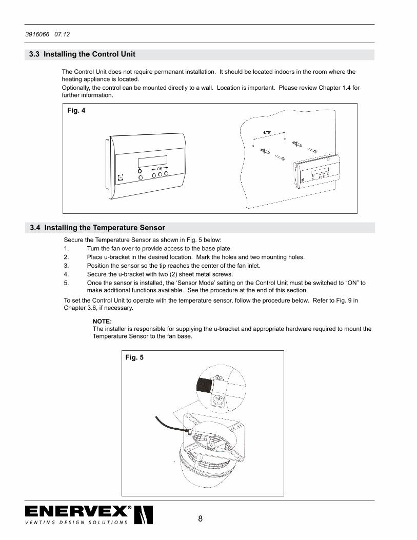
3.3InstallingtheControlUnit The Control Unit does not require permanant installation. It should be located indoors in the room where the heating appliance is located. Optionally, the control can be mounted directly to a wall. Location is important. Please review Chapter 1.4 for further information.
3.4InstallingtheTemperatureSensor Secure the Temperature Sensor as shown in Fig. 5 below: 1. Turn the fan over to provide access to the base plate. 2. Place u-bracket in the desired location. Mark the holes and two mounting holes. 3. Position the sensor so the tip reaches the center of the fan inlet. 4. Secure the u-bracket with two (2) sheet metal screws. 5. Once the sensor is installed, the ‘Sensor Mode’ setting on the Control Unit must be switched to “ON” to make additional functions available. See the procedure at the end of this section.
TosettheControlUnittooperatewiththetemperaturesensor,followtheprocedurebelow.RefertoFig.9in Chapter 3.6, if necessary.
Fig.5
NOTE: The installer is responsible for supplying the u-bracket and appropriate hardware required to mount the Temperature Sensor to the fan base.

9
3916066 07.12
Fig.6 Fig.7
1. RemovetheoutercoverofthePowerUnit.Applypower(120VAC)tothePowerUnitandturntheswitchto the “ON” position. Turn on the Control Unit (H, Fig. 9). 2. On the Control Unit, press the “OK” button (F, Fig. 9) and hold it down for at least three (3) seconds to display the set-up menu. Use the arrow buttons (E and G, Fig. 9) to scroll to the Sensor Menu (Menu 2) and press the “OK” button. 3. Use the arrow buttons to scroll to the Sensor Mode Menu (Menu 21) and press “OK”. The display on the Control Unit should read “Set Mode OFF.” 4. Press the arrow button to change the setting to “ON”. The display on the Control Unit should now read “Set Mode ON.” Press the “OK” button on the Control Unit. 5. Use the arrow buttons to scroll to the Exit Menu. Press “OK” to exit the Sensor Menu. Again use the arrow buttons to exit the Set-Up menu. Press “OK” to return to the main display. The Control Unit should now be properly programmed to operate with the temperature sensor.
3.5InstallingtheProvenDraftSwitch(ifapplicable) IftheEW40isusedtocontrolagas-firedheatingappliance,aProvenDraftSwitch(soldseparately)mustbe installed. A PDS-1 is available from EXHAUSTO, and is installed as shown below. For wiring details, see Fig. 11. Please consult the PDS-1 installation manual for in-depth installation instructions.
ENDURA PLASTICSXP042105-1-1REV A0.05” WC PRMOUNT DIAPHRAGM VERTICAL
UR
Mounting holes
Connection fortubing at the bottom of
the enclosure
ENDURA PLASTICSXP042105-1-1REV A0.05” WC PRMOUNT DIAPHRAGM VERTICAL
UR
Mounting holes
Connection fortubing at the bottom of
the enclosure
Junction Box
Chimney Fan
PDS1
EXHAUSTO
PDS 1
Probe
Silicone Tubing
NOTE: The Power Unit must be wired accorded to Chapter 4.2 before following this procedure..

10
3916066 07.12
3.6InstallingtheRepeaterUnit(ifapplicable) ARepeaterUnitistypicallyusedininstallationsthatrequiretheControlUnittobeplacedfarawayfromthePowerUnit, and in those where the communication signal is transmitted through multiple obstructions.
AfterwiringthePowerUnitaccordingtoChapter4.2,followthesestepstosetupandinstalltheRepeaterUnit: 1. Connect a cord (not included) with plug to terminals 1 and 2 on the RepeaterUnit. See Fig. 8 above. Plug into areceptacleandpressthe“Power”button(D).Removethecover. 2. On the Control Unit (Fig. 9), press the “OK” button (F) and hold it down for at least three (3) seconds to display the Set-Up Menu. Use the arrow buttons (E & G) to go to the Network Menu (Menu 5) and press “OK”. Use the arrow buttons to go to the Add Node Menu (Menu 51) and press “OK”. The display should read “Press Button on Node”. Press the “OK” button on the Control Unit. 3. OntheRepeaterUnit(Fig.8),pressthe“Connect”button(B)andholditdownforatleast3seconds.The display on the Control Unit should now read “Node included”. Press the “OK” button on the Control Unit. 4. On the Control Unit, go to the Network Menu (Menu 5), use arrows to go to the Signal Test Menu (Menu 53) and press“OK”.Thedisplayshouldnowshowflashingdottedlines. 5. PlacetheRepeaterUnitinthedesiredlocation(donotpermanentlyattachuntilsteps6-8arecompleted).Itmust be installed somewhere between the Control Unit and Power Unit. 6. OntheRepeaterUnit,presstheConnectbutton(B)tocheckthesignalstrength.ThesendandreceiveLEDs (AandC)willlightupifthecommunicationsignalisacceptable.The“Receive”LEDindicatesthattheRepeater hascommunicatedwiththeControlUnitandthe“Send”LEDindicatesthattheRepeaterhascommunicated with the Power Unit. 7. Ifnecessary,movetheRepeaterUnitarounduntilcommunicationhasbeenestablishedbetweenallthreeunits (both LEDs must be illuminated at the completion of the test). 8. When both LEDs are illuminated, press “OK”. The display will show a running dot indicating that the network is now being checked. If the display reads “OK”, the unit has passed the installation test. If not, the test has failed, and it must be repeated. 9. Use the arrow buttons to scroll to the exit menu. Press “OK” to exit the Network Menu. Again use the arrow buttons to exit the Set-Up menu. Press “OK” to return to the main display. 10. PermanentlyinstalltheRepeaterUnit.Ifdesired,theRepeaterUnitcanbehard-wiredinsteadofusingaplugand receptacle.
Fig.8 Fig.9
OK
EFGH
Power
1 2
L N
Connect/Signal
SendReceive
A B C D
RepeaterUnit
Control Unit
NOTE: 1.Nomorethanthree(3)RepeaterUnitscanbeusedinasingleinstallation.2.TheRepeaterUnitmustbeinstalledindoors.3.WhenaRepeaterUnitisinstalled,thecommunicationmaybedelayeduptoone(1)second per unit because of the additional communication activity required.

11
3916066 07.12
3.7ProgrammingthePowerUnit(ifnecessary)
The Power Unit should be programmed to operate with the Control Unit when it is received by the customer. In the eventthatitisnotprogrammed,wirethePowerUnitaccordingtoChapter4.2,andfollowthestepsbelow.Referto Fig. 10 below and Fig. 9 in Chapter 3.6 if necessary.
1. Applypower(120VAC)tothePowerUnitandturnthePowerUnitswitchtotheonposition.Turnonthe Control Unit. 2. On the Control Unit, press the “OK” button and hold it down for at least 3 seconds to display the Set-Up Menu. Use the arrow buttons to scroll to the Network Menu (Menu 5) and press the “OK” button. 3. Use the arrow buttons to scroll to the Add Node Menu (Menu 51) and press “OK”. The display on the Control Unit should read “Press Button on Node.” 4. Press the “Connect/Signal” button (J) located on the inside of the Power Unit. Hold the button down until the Send/Receive(LandK)LEDlightsilluminate.ThedisplayontheControlUnitshouldnowread “Node included.” Press the “OK” button on the Control Unit. 5. Use the arrow buttons to scroll to the Exit Menu. Press “OK” to exit the Network Menu. Again use the arrow buttons to exit the Set-Up menu. Press “OK” to return to the main display. The Power Unit should now be properly programmed.
3.8Refiring(ifapplicable)
Therefirefunctionisforusewithsolid-fuelburningappliancesonly.Theusershouldrunthefanatmax.speedfor 3minuteswhennewfuelisaddedtothefireplace.Thiswillpreventspillageintotheroom.
TheautomaticrefiringfunctionismadeavailablethroughtheTemperatureSensor.Ifthetemperatureinthe chimneyfallsbelowacertainlevel,thecontrolwillalerttheusertoaddmorefueltothefireplace.Thedisplay ontheControlUnitwillread“REFIRING”,andalowaudiosignalwillsound5times.Theusershouldpress the“ON/OFF”buttonontheControlUnitBEFOREaddingnewfueltothefireplace.Thiswillsignalthechimneyfan to run at max. speed for 3 minutes before returning to the set operating speed.
9 Nreg
8 L1
10 PE
3 PE
2 N
1 L 7654
SUPPLY
115VAC 60Hz
FAN
MAX 6A Load
Fuse T6.3A H
POWER
ALARM IN SENSOR
Send
Receive
Connect/Signal
Fig.10
J
L
K
12
3916066 07.12
4.1 General
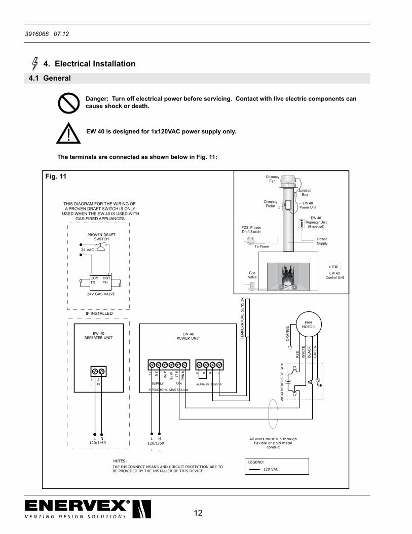
Danger:Turnoffelectricalpowerbeforeservicing.Contactwithliveelectriccomponentscancause shock or death.
EW40isdesignedfor1x120VACpowersupplyonly.
TheterminalsareconnectedasshownbelowinFig.11:
Fig.11
RED
WH
ITE
BLA
CK
GREE
N
FANMOTOR
120/1/60
NOTES: THE DISCONNECT MEANS AND CIRCUIT PROTECTION ARE TO BE PROVIDED BY THE INSTALLER OF THIS DEVICE
All wires must run throughflexible or rigid metal
conduit
LEGEND:
120 VAC
WEA
THER
PRO
OF
BO
X
NL
EW 40POWER UNIT O
RAN
GE
9 Nreg
8 L1
10 PE
3 PE
2 N
1 L 7654
SUPPLY
115VAC 60Hz
FAN
MAX 6A Load
ALARM IN SENSOR
TEM
PERAT
URE
SEN
SO
R
1 2L N
120/1/60NL
EW 40REPEATER UNIT
24V GAS VALVE
COMTR
HOTTH
PROVEN DRAFTSWITCH
24 VAC
IF INSTALLED
THIS DIAGRAM FOR THE WIRING OF A PROVEN DRAFT SWITCH IS ONLY
USED WHEN THE EW 40 IS USED WITHGAS-FIRED APPLIANCES
+ _
4. Electrical Installation
13
3916066 07.12
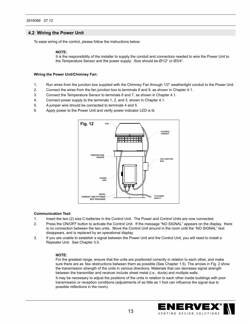
4.2WiringthePowerUnit
To ease wiring of the control, please follow the instructions below:
WiringthePowerUnit/ChimneyFan:
1. RunwiresfromthejunctionboxsuppliedwiththeChimneyFanthrough 1/2” weathertight conduit to the Power Unit. 2. Connect the wires from the fan junction box to terminals 8 and 9, as shown in Chapter 4.1. 3. Connect the Temperature Sensor to terminals 6 and 7, as shown in Chapter 4.1. 4. Connect power supply to the terminals 1, 2, and 3, shown in Chapter 4.1. 5. A jumper wire should be connected to terminals 4 and 5. 6. Apply power to the Power Unit and verify power indicator LED is lit.
Communication Test: 1. Insert the two (2) size C-batteries in the Control Unit. The Power and Control Units are now connected. 2. Press the ON/OFF button to activate the Control Unit. If the message “NO SIGNAL” appears on the display, there is no connection between the two units. Move the Control Unit around in the room until the “NO SIGNAL” text disappears, and is replaced by an operational display. 3. If you are unable to establish a signal between the Power Unit and the Control Unit, you will need to install a RepeaterUnit.SeeChapter3.5.
Fig.12
NOTE: For the greatest range, ensure that the units are positioned correctly in relation to each other, and make sure there are as few obstructions between them as possible (See Chapter 1.5). The arrows in Fig. 2 show the transmission strength of the units in various directions. Materials that can decrease signal strength between the transmitter and receiver include sheet metal (i.e., ducts) and multiple walls.It may be necessary to adjust the positions of the units in relation to each other inside buildings with poor transmissionorreceptionconditions(adjustmentsofaslittleas1footcaninfluencethesignalduetopossiblereflectionsintheroom).
NOTE: It is the responsibility of the installer to supply the conduit and connectors needed to wire the Power Unit to the Temperature Sensor and the power supply. Size should be Ø1/2” or Ø3/4”.

14
3916066 07.12
5.StartupandConfiguration
5.1ControlUnitSettings AccessingtheSet-UpMenu. To access this menu, press the “OK” button (F, Fig. 9) and hold it down for at least 3 seconds. To exit the menu, press the “ON/OFF” button (H, Fig. 9). Use the arrow buttons to scroll back and forth between the various menu items. The menu setting are show in the table.
Main Menu Sub-Menus Description Factory Setting
1 EXIT Exit from Main Menu top operational display
2SENSOR 20 EXIT Exit to Main Menu
21SENSORMODE If ON is selected: the control unit is now set to operate with a temperature sensor.If OFF is selected: the control functions only as a speed regulator
OFF
22STARTTEMP Temperature limit for control to start automatically. Setting: 41-212ºF (5-100ºC).
77ºF
23 STOP TEMP Temperature limit for control to stop automatically. Setting: 32-203ºF (0-95ºC).
203ºF
24ALARMTEMP Temperaturelimitforthecontroltotriggerachimneyfirealarm. Setting: 212-752ºF (100-400ºC).
626ºF
3TIMER 30 EXIT Exit to Main Menu
31 BOOST TIME Timer for setting boost time where the chimney fan delivers maximum speed and draft when heating appliance is cold. Setting: 1-15 minutes
7 minutes
32 STOP TIME Timer for setting post purge where the chimney fan is removing residualproductsofcombustionafterthefireisout.Setting:1-45minutes.
45 minutes
4ALARM 40 EXIT Exit to Main Menu
41 LOG Displaysthelastfiveerrorsoralarms
42RESETLOG Deletes all non-active errors or alarms in the memory.
5NETWORK 50 EXIT Exit to Main Menu
51 ADD NODE MenuusedwhenconnectingaUnit(likeRepeaterUnit)tothenetwork
52 DELETE NODE Menu used when disconnecting a unit from the network.
53 SIGNAL TEST Menu that keeps the Control Unit active and allows communication checkstoberunonPowerand/orRepeaterUnits.
54RECEIVEREPLICATION Not used
55SENDREPLICATION Not used
56RESETCONTROLLER ResetstheControlUnittoNeutralsotheentiresystemhastobereinstalled.AllNodes(PowerUnit/RepeaterUnit)mustbedeleted(Menu 52) before a network can be set up again (Menu 51)
6SERVICE 60 EXIT Exit to Main Menu.
61VERSION Displays software version number
62FACTORYSETTING Re-establishedFactorySetting
63 LANGUAGE To select language: English, Danish or German ENGLISH
64 MIN SPEED Settingofminimumfanspeed.Settings:35-75V 65V
7 SETTING 70 EXIT Exit to Main Menu
71CONTRAST Setting the display Contrast 70%
72 BACKLIGHT Switch backlight ON and OFF ON
73SPEAKER YES:Signalemittedwhenrefiring(morefuel)isrequiredNO: No signals
YES
15
3916066 07.12
6.MaintenanceandTroubleshooting
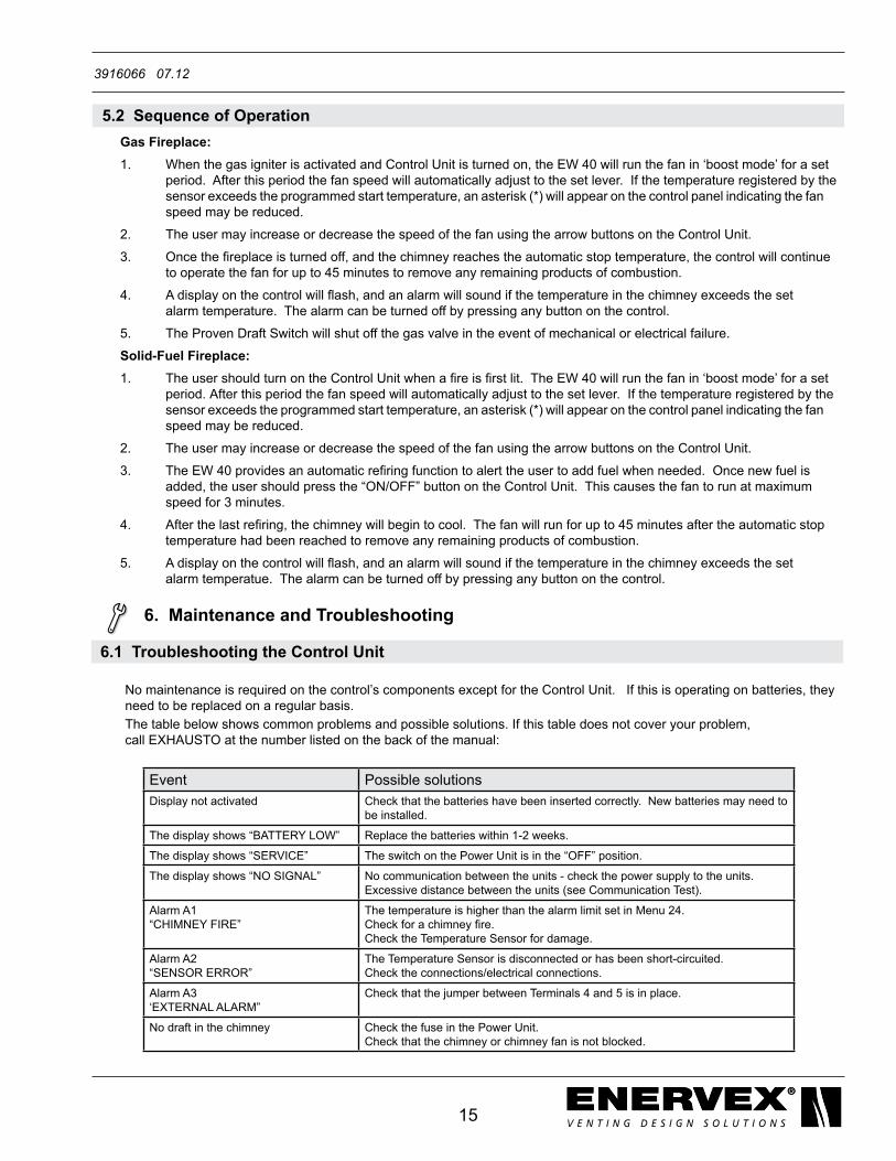
6.1TroubleshootingtheControlUnit No maintenance is required on the control’s components except for the Control Unit. If this is operating on batteries, they need to be replaced on a regular basis. The table below shows common problems and possible solutions. If this table does not cover your problem, call EXHAUSTO at the number listed on the back of the manual:
Event Possible solutionsDisplay not activated Check that the batteries have been inserted correctly. New batteries may need to
be installed.
Thedisplayshows“BATTERYLOW” Replacethebatterieswithin1-2weeks.
Thedisplayshows“SERVICE” The switch on the Power Unit is in the “OFF” position.
The display shows “NO SIGNAL” No communication between the units - check the power supply to the units.Excessive distance between the units (see Communication Test).
Alarm A1 “CHIMNEYFIRE”
The temperature is higher than the alarm limit set in Menu 24.Checkforachimneyfire.Check the Temperature Sensor for damage.
Alarm A2“SENSORERROR”
The Temperature Sensor is disconnected or has been short-circuited.Check the connections/electrical connections.
Alarm A3‘EXTERNALALARM”
Check that the jumper between Terminals 4 and 5 is in place.
No draft in the chimney Check the fuse in the Power Unit.Check that the chimney or chimney fan is not blocked.
5.2SequenceofOperation Gas Fireplace: 1. When the gas igniter is activated and Control Unit is turned on, the EW 40 will run the fan in ‘boost mode’ for a set period. After this period the fan speed will automatically adjust to the set lever. If the temperature registered by the sensor exceeds the programmed start temperature, an asterisk (*) will appear on the control panel indicating the fan speed may be reduced.
2. The user may increase or decrease the speed of the fan using the arrow buttons on the Control Unit.
3. Oncethefireplaceisturnedoff,andthechimneyreachestheautomaticstoptemperature,thecontrolwillcontinue to operate the fan for up to 45 minutes to remove any remaining products of combustion.
4. Adisplayonthecontrolwillflash,andanalarmwillsoundifthetemperatureinthechimneyexceedstheset alarm temperature. The alarm can be turned off by pressing any button on the control.
5. The Proven Draft Switch will shut off the gas valve in the event of mechanical or electrical failure.
Solid-Fuel Fireplace: 1. The user should turn on theControlUnitwhenafireisfirstlit.TheEW40willrunthefanin‘boostmode’foraset period. After this period the fan speed will automatically adjust to the set lever. If the temperature registered by the sensor exceeds the programmed start temperature, an asterisk (*) will appear on the control panel indicating the fan speed may be reduced.
2. The user may increase or decrease the speed of the fan using the arrow buttons on the Control Unit.
3. TheEW40providesanautomaticrefiringfunctiontoalerttheusertoaddfuelwhenneeded.Oncenewfuelis added, the user should press the “ON/OFF” button on the Control Unit. This causes the fan to run at maximum speed for 3 minutes.
4. Afterthelastrefiring,thechimneywillbegintocool.Thefanwillrunforupto45minutesaftertheautomaticstop temperature had been reached to remove any remaining products of combustion.
5. Adisplayonthecontrolwillflash,andanalarmwillsoundifthetemperatureinthechimneyexceedstheset alarm temperatue. The alarm can be turned off by pressing any button on the control.

ENERVEX Inc.1685 Bluegrass Lakes Pkwy.Alpharetta, GA 30004
P: 770.587.3238F: 770.587.4731T: [email protected]
3916066 07.12