every building matters residential & light commercial air ...€¦ · residential & light...
TRANSCRIPT
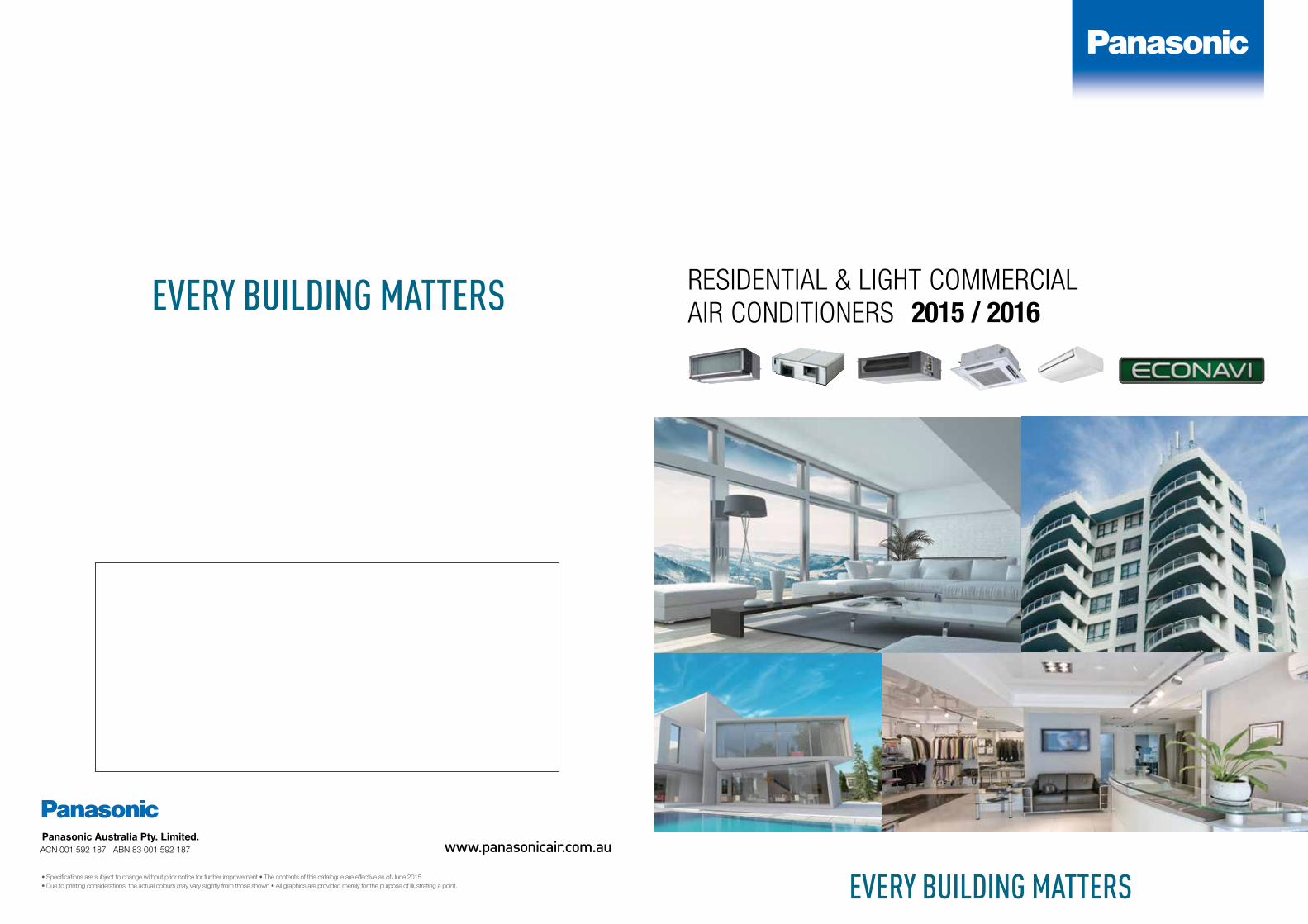
RESIDENTIAL & LIGHT COMMERCIAL AIR CONDITIONERS 2015 / 2016
EVERY BUILDING MATTERSApril, 2012• Specifications are subject to change without prior notice for further improvement • The contents of this catalogue are effective as of June 2015. • Due to printing considerations, the actual colours may vary slightly from those shown • All graphics are provided merely for the purpose of illustrating a point.
EVERY BUILDING MATTERS
www.panasonicair.com.au

As we move towards our Centenary in 2018, our new brand slogan encapsulates Panasonic’s vision of expanding and pursuing a better life for each of our customers. Working with our many partners, we operate in a wide range of fields such as the home, community, business and travel realising a better world globally through its contribution to the environment and other activies, in both its B2C and B2B businesses.
A Better Life, A Better World
2 3

4 5
2014 Brand Ranking Top 10
Panasonic Eco City Tianjin, China
1 FORD
2 TOYOTA
3 HONDA
4 NISSAN
5
6 NOKIA
7 SONY
8 ADIDAS
9 DANONE
10 DELL
Interbrand has announced its 2014 ranking of Best Global Green Brands. In this year’s ranking Panasonic was ranked number five, fulfilling our eco pledge “For future generations, Panasonic aims to become the No.1 Green Innovation Company in the Electronics Industry.”
At Panasonic, our eco pledge is more than just a tagline; it’s a harmonious way of life that we take very seriously. Panasonic was founded based on the philosophy of contributing to progress in society and to enriching people’s lives through business activities. By offering products that help
people lead better, greener lives, we are making good on our strong commitment to continuous environmental sustainability management.
Interbrand’s Best Global Green Brands 2014 report is a look at sustainability with performance data powered by Deloitte and consumer perception data. Interbrand evaluates organisations based on market perception; actual environmental performance; and products and services.* Source: Best Global Green Brands 2014, Interbrand. Go to www.bestglobalgreenbrands.com for more information.
For Future GenerationsPanasonic aims to become the No.1 green innovation
company in the electronics industry
The 2014 Best GlobalGreenBrands
6 7
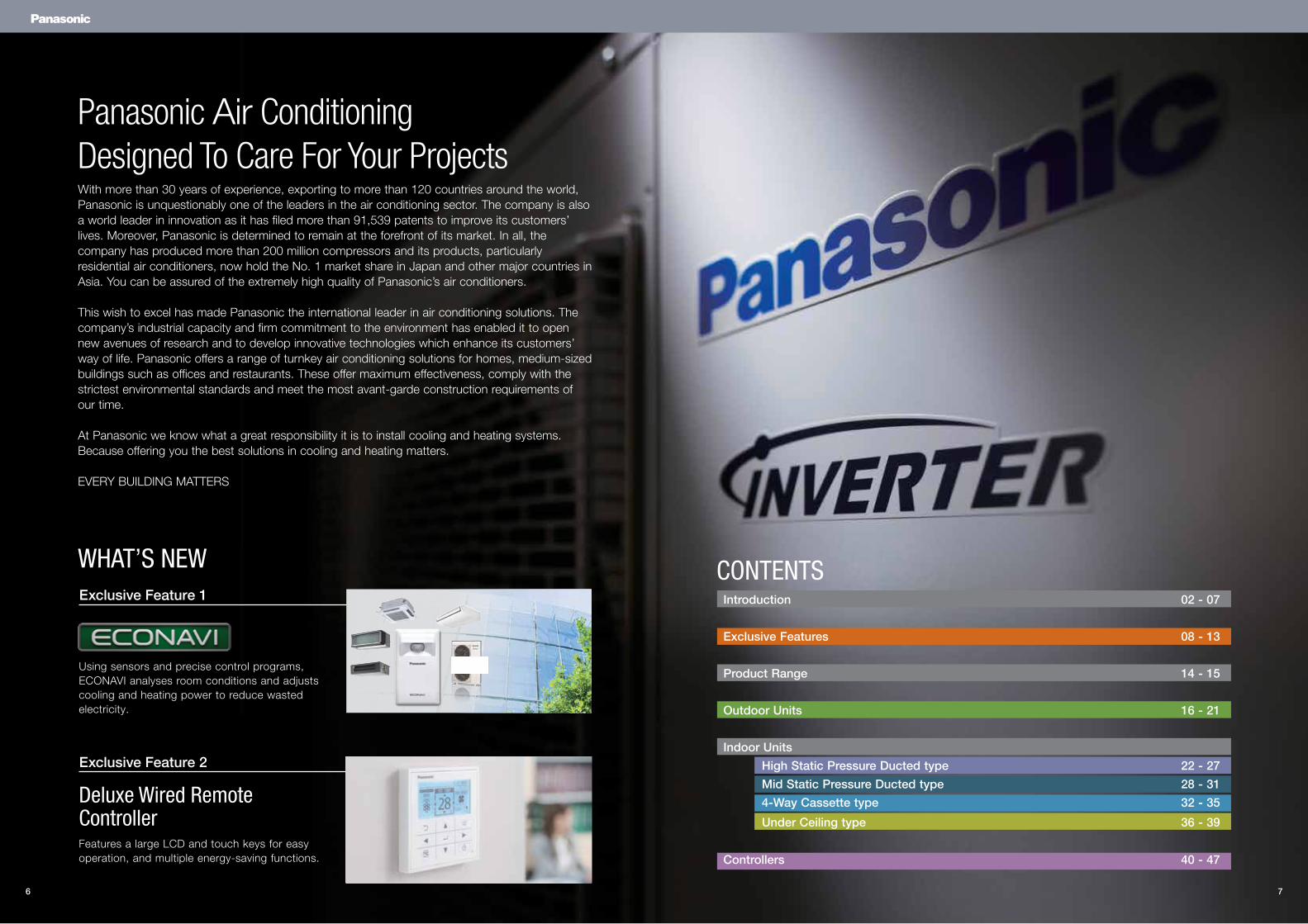
With more than 30 years of experience, exporting to more than 120 countries around the world, Panasonic is unquestionably one of the leaders in the air conditioning sector. The company is also a world leader in innovation as it has filed more than 91,539 patents to improve its customers’ lives. Moreover, Panasonic is determined to remain at the forefront of its market. In all, the company has produced more than 200 million compressors and its products, particularly residential air conditioners, now hold the No. 1 market share in Japan and other major countries in Asia. You can be assured of the extremely high quality of Panasonic’s air conditioners.
This wish to excel has made Panasonic the international leader in air conditioning solutions. The company’s industrial capacity and firm commitment to the environment has enabled it to open new avenues of research and to develop innovative technologies which enhance its customers’ way of life. Panasonic offers a range of turnkey air conditioning solutions for homes, medium-sized buildings such as offices and restaurants. These offer maximum effectiveness, comply with the strictest environmental standards and meet the most avant-garde construction requirements of our time.
At Panasonic we know what a great responsibility it is to install cooling and heating systems. Because offering you the best solutions in cooling and heating matters.
EVERY BUILDING MATTERS
Panasonic Air Conditioning Designed To Care For Your Projects
CONTENTSWHAT’S NEW
Using sensors and precise control programs, ECONAVI analyses room conditions and adjusts cooling and heating power to reduce wasted electricity.
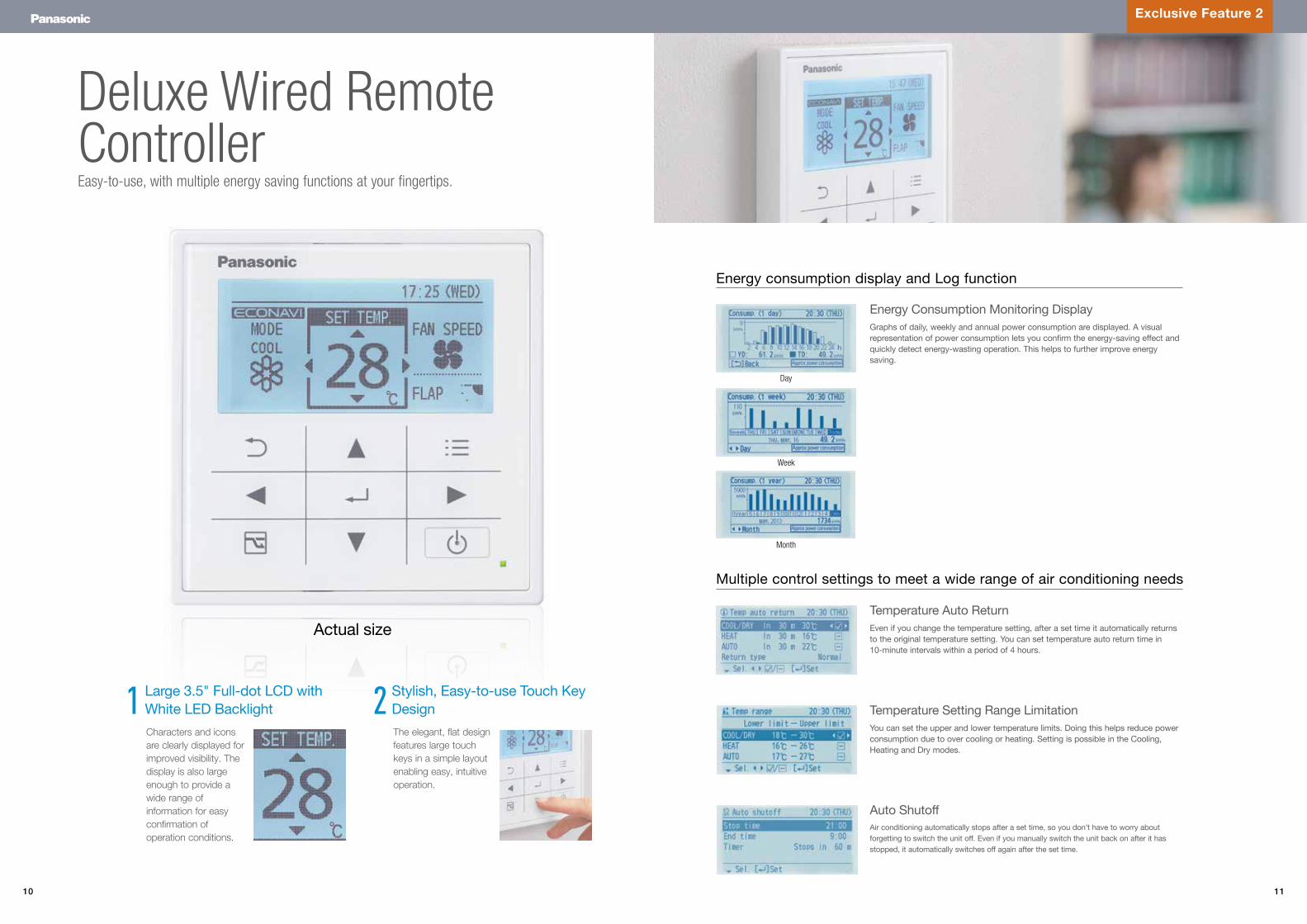
Features a large LCD and touch keys for easy operation, and multiple energy-saving functions.
Exclusive Feature 1
Exclusive Feature 2
Deluxe Wired Remote Controller
Introduction 02 - 07
Exclusive Features 08 - 13
Product Range 14 - 15
Outdoor Units 16 - 21
Indoor Units
High Static Pressure Ducted type 22 - 27
Mid Static Pressure Ducted type 28 - 31
4-Way Cassette type 32 - 35
Under Ceiling type 36 - 39
Controllers 40 - 47
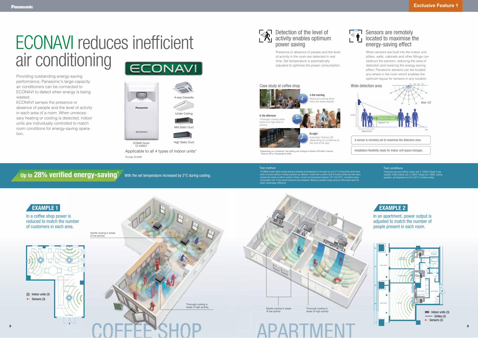
ECONAVI reduces inefficientair conditioning
Exclusive Feature 1
Applicable to all 4 types of indoor units*
Detection of the level of activity enables optimum power saving
ECONAVI SensorCZ-CENSC1
Presence or absence of people and the level of activity in the room are detected in real time. Set temperature is automatically adjusted to optimise the power consumption.
Reduced cooling when there are fewer people
Sensors are remotely located to maximise the energy-saving effectWhen sensors are built into the indoor unit, pillars, walls, cabinets and other fittings can obstruct the sensors, reducing the area of detection and lowering the energy-saving effect. Panasonic sensors can be located any where in the room which enables the optimum layout for sensors in any location.
Dead Zone
*Depending on conditions, the setting can change to Switch Off After 3 Hours, Thermo Off or Temperature Shift.
Approx 1m
Detection area
7m
2.5m
-60°
1m 3m 5m 7m
60°
-40°
-20° 20°
40°
0°
In the morning
A sensor is remotely set to maximise the detection area.
Installation flexibility ready for indoor unit layout changes.
Wide detection areaCase study at coffee shop
Wide 120˚
Automatic Thermo Off depending on conditions at the end of the day*
At night
Thorough cooling when there is a high level of activity
In the afternoon
With the set temperature increased by 2°C during cooling.Up to 28% verified energy-saving* *ECONAVI sensor allows energy saving by allowing set temperature to increase by up to 2°C during times when lower levels of human activity or human presence are detected. Tested with a uniform level of human activity and with doors opened and closed a uniform number of times. At each set temperature between 24°C and 28°C, cumulative power consumption over 3 hour period measured and compared. Maximum possible energy saving is 28% based upon the power consumption difference.
Test method*Panasonic test room (29m2). Indoor unit: S-100PU1 (Single 4-way Cassette 10kW) Outdoor unit: U-100PE1 (Single DLX 10kW). Cooling operation, set temperature of 24 to 28°C, Hi airflow setting.
Test conditions
Gentle cooling in areas of low activity
Thorough cooling in areas of high activity Gentle cooling in areas
of low activityThorough cooling in areas of high activity
Providing outstanding energy-saving performance, Panasonic's large capacity air conditioners can be connected to ECONAVI to detect when energy is being wasted. ECONAVI senses the presence or absence of people and the level of activity in each area of a room. When unneces-sary heating or cooling is detected, indoor units are individually controlled to match room conditions for energy-saving opera-tion.
*Except 20.0kW
:
::
WALK-INCLOSET
BATH
ENTRANCEKITCHEN
BALCONY
BALCONY
Gentle cooling in areasof low activity
Thorough cooling inareas of high activity
BALCONY
BALCONY
MASTER
EXAMPLE 1In a coffee shop power is reduced to match the number of customers in each area.
COUNTER TABLE
SEATING AREA
ENTRANCE
:
:
Indoor units (3)
Indoor units (3)Grilles (3)
Sensors (3)
Sensors (3)
ERA
LIVING
BEDROOM
BEDROOM
EXAMPLE 2In an apartment, power output isadjusted to match the number ofpeople present in each room.
t
A
t
A
High Static Duct
Mid Static Duct
4-way Cassette
Under Ceiling
8 9
10 11
Multiple control settings to meet a wide range of air conditioning needs
Day
Week
Month
Exclusive Feature 2
Large 3.5" Full-dot LCD with White LED Backlight
Stylish, Easy-to-use Touch Key Design
Characters and icons are clearly displayed for improved visibility. The display is also large enough to provide a wide range of information for easy confirmation of operation conditions.
The elegant, flat design features large touch keys in a simple layout enabling easy, intuitive operation.
Energy consumption display and Log function
Actual size
Deluxe Wired Remote Controller
1 2You can set the upper and lower temperature limits. Doing this helps reduce power consumption due to over cooling or heating. Setting is possible in the Cooling, Heating and Dry modes.
Even if you change the temperature setting, after a set time it automatically returns to the original temperature setting. You can set temperature auto return time in 10-minute intervals within a period of 4 hours.
Graphs of daily, weekly and annual power consumption are displayed. A visual representation of power consumption lets you confirm the energy-saving effect and quickly detect energy-wasting operation. This helps to further improve energy saving.
Air conditioning automatically stops after a set time, so you don’t have to worry about forgetting to switch the unit off. Even if you manually switch the unit back on after it has stopped, it automatically switches off again after the set time.
Temperature Setting Range Limitation
Temperature Auto Return
Energy Consumption Monitoring Display
Auto Shutoff
Easy-to-use, with multiple energy saving functions at your fingertips.
12 13
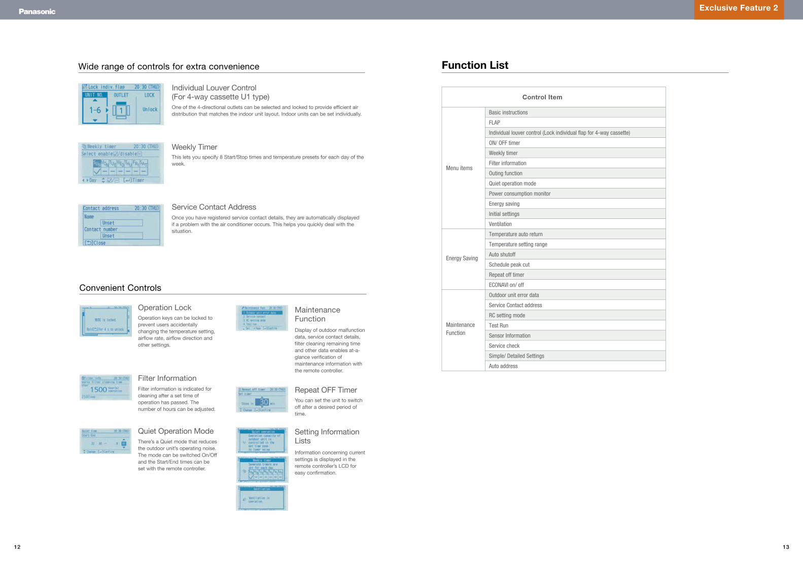
Individual Louver Control (For 4-way cassette U1 type)
Weekly Timer
Service Contact Address
One of the 4-directional outlets can be selected and locked to provide efficient air distribution that matches the indoor unit layout. Indoor units can be set individually.
This lets you specify 8 Start/Stop times and temperature presets for each day of the week.
Once you have registered service contact details, they are automatically displayed if a problem with the air conditioner occurs. This helps you quickly deal with the situation.
Wide range of controls for extra convenience Function List
Operation Lock
Filter Information
Setting Information Lists
Maintenance Function
Quiet Operation Mode
Operation keys can be locked to prevent users accidentally changing the temperature setting, airflow rate, airflow direction and other settings.
Display of outdoor malfunction data, service contact details, filter cleaning remaining time and other data enables at-a-glance verification of maintenance information with the remote controller.
There’s a Quiet mode that reduces the outdoor unit’s operating noise. The mode can be switched On/Off and the Start/End times can be set with the remote controller.
Filter information is indicated for cleaning after a set time of operation has passed. The number of hours can be adjusted.
Information concerning current settings is displayed in the remote controller’s LCD for easy confirmation.
Convenient Controls
Repeat OFF TimerYou can set the unit to switch off after a desired period of time.
Hi-Spec Remote Con-Exclusive Feature 2
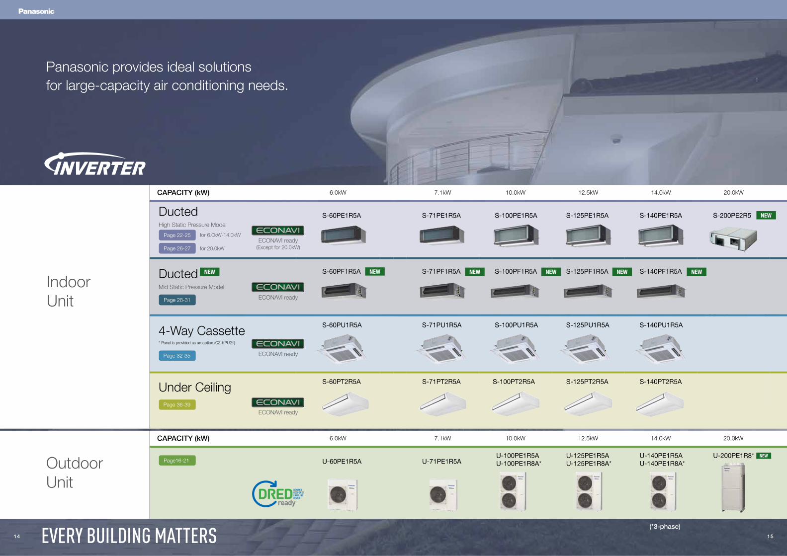
CAPACITY (kW) 6.0kW 7.1kW 10.0kW 12.5kW 14.0kW 20.0kW
CAPACITY (kW) 6.0kW 7.1kW 10.0kW 12.5kW 14.0kW 20.0kW
Outdoor Unit
Indoor Unit
Panasonic provides ideal solutions for large-capacity air conditioning needs.
U-60PE1R5AU-100PE1R5AU-100PE1R8A*
U-125PE1R5AU-125PE1R8A*
U-140PE1R5AU-140PE1R8A*
U-200PE1R8*
(*3-phase)
U-71PE1R5A
S-60PE1R5A
S-60PF1R5A
S-100PE1R5A
S-100PF1R5A
S-71PE1R5A
S-71PF1R5A
S-125PE1R5A
S-125PF1R5A
S-140PE1R5A
S-140PF1R5A
S-200PE2R5
S-60PU1R5A
S-60PT2R5A
S-100PU1R5A
S-100PT2R5A
S-71PU1R5A
S-71PT2R5A
S-125PU1R5A
S-125PT2R5A
S-140PU1R5A
S-140PT2R5A
4-Way Cassette
Under Ceiling
* Panel is provided as an option (CZ-KPU21)
Page 32-35
Page 36-39
DuctedHigh Static Pressure Model
for 6.0kW-14.0kW
for 20.0kWECONAVI ready
(Except for 20.0kW)
ECONAVI ready
ECONAVI ready
Page 22-25
Page 26-27
Page16-21
DuctedMid Static Pressure Model
ECONAVI readyPage 28-31
NEW
NEW
14 15EVERY BUILDING MATTERS
NEW NEW NEW NEW NEW
NEW
16 17
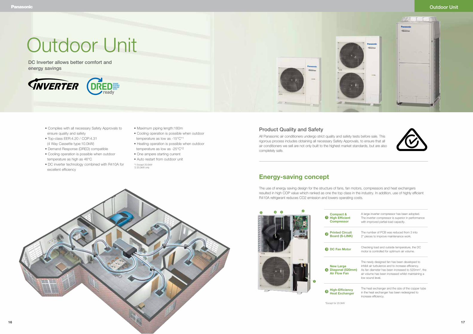
Outdoor Unit
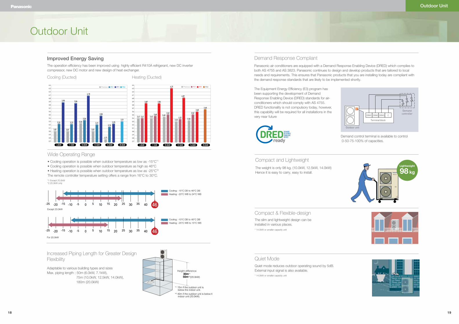
The use of energy saving design for the structure of fans, fan motors, compressors and heat exchangers resulted in high COP value which ranked as one the top class in the industry. In addition, use of highly efficient R410A refrigerant reduces CO2 emission and lowers operating costs.
All Panasonic air conditioners undergo strict quality and safety tests before sale. This rigorous process includes obtaining all necessary Safety Approvals, to ensure that all air conditioners we sell are not only built to the highest market standards, but are also completely safe.
Energy-saving concept
Product Quality and Safety
A large inverter compressor has been adopted. The inverter compressor is superior in performance with improved partial-load capacity.
The number of PCB was reduced from 3 into 2* pieces to improve maintenance work.
Checking load and outside temperature, the DC motor is controlled for optimum air volume.
The newly designed fan has been developed to inhibit air turbulence and to increase efficiency. As fan diameter has been increased to 520mm*, the air volume has been increased whilst maintaining a low sound level.
The heat exchanger and the size of the copper tube in the heat exchanger has been redesigned to increase efficiency.
Printed Circuit Board (S-LINK)
Compact & High Efficient Compressor
DC Fan Motor
New Large Diagonal (520mm) Air Flow Fan
High-Efficiency Heat Exchanger
524 3
1
1
2
3
4
5
• Complies with all necessary Safety Approvals to ensure quality and safety
• Top-class EER:4.20 / COP:4.31 (4 Way Cassette type:10.0kW)• Demand Response (DRED) compatible• Cooling operation is possible when outdoor
temperature as high as 46°C• DC inverter technology combined with R410A for
excellent efficiency
• Maximum piping length:180m• Cooling operation is possible when outdoor
temperature as low as -15°C*1
• Heating operation is possible when outdoor temperature as low as -25°C*2
• One ampere starting current• Auto restart from outdoor unit
Outdoor Unit
DC Inverter allows better comfort and energy savings
*1 Except 20.0kW*2 20.0kW only
*Except for 20.0kW
18 19
Increased Piping Length for Greater Design Flexibility
Adaptable to various building types and sizesMax. piping length : 50m (6.0kW, 7.1kW), 75m (10.0kW, 12.5kW, 14.0kW), 180m (20.0kW)
For 20.0kW
Compact and Lightweight
The weight is only 98 kg. (10.0kW, 12.5kW, 14.0kW)Hence it is easy to carry, easy to install.
Compact & Flexible-designThe slim and lightweight design can be installed in various places.
Quiet ModeQuiet mode reduces outdoor operating sound by 5dB. External input signal is also available.
FS MultiSingle Split
98 kgLightweight
• Cooling operation is possible when outdoor temperature as low as -15°C*1
• Cooling operation is possible when outdoor temperature as high as 46°C• Heating operation is possible when outdoor temperature as low as -25°C*2
The remote controller temperature setting offers a range from 16°C to 30°C.
Cooling
10.0kW6.0kW
3.01
3.24
3.90
3.31
4.10
3.263.36
7.1kW
3.84
3.01
3.23
12.5kW
3.50
3.01
3.21 3.25
2.77
3.15
14.0kW 20.0kW
4.4
4.3
4.2
4.1
4.0
3.9
3.8
3.7
3.6
3.5
3.4
3.3
3.2
3.1
3.0
2.9
2.8
2.7
Previous PE1 PF1 PE2
10.0kW6.0kW 7.1kW 12.5kW 14.0kW 20.0kW
4.4
4.3
4.2
4.1
4.0
3.9
3.8
3.7
3.6
3.5
3.4
3.3
3.2
3.1
3.0
2.9
2.8
2.7
Previous PE1
3.41 3.41
3.87 3.85
3.60
4.31
4.02
3.423.48 3.45
3.52
3.323.37 3.34
3.52
PF1 PE2
3.68
The operation efficiency has been improved using highly efficient R410A refrigerant, new DC inverter compressor, new DC motor and new design of heat exchanger.
Improved Energy Saving
Cooling (Ducted) Heating (Ducted)
Wide Operating Range
Except 20.0kW
Panasonic air conditioners are equipped with a Demand Response Enabling Device (DRED) which complies to both AS 4755 and AS 3823. Panasonic continues to design and develop products that are tailored to local needs and requirements. This ensures that Panasonic products that you are installing today are compliant with the demand response standards that are likely to be implemented shortly.
The Equipment Energy Efficiency (E3) program has been supporting the development of Demand Response Enabling Device (DRED) standards for air-conditioners which should comply with AS 4755. DRED functionality is not compulsory today, however, this capability will be required for all installations in the very near future
Outdoor unit
DRM1 DRM2 DRM3 C
Terminal block
Demand controller
Demand control terminal is available to control 0-50-75-100% of capacities.
Demand Response Compliant
Outdoor Unit
Outdoor Unit
Cooling: -15°C DB to 46°C DB
Heating: -20°C WB to 24°C WB
Cooling: -10°C DB to 46°C DB
Heating: -25°C WB to 15°C WB
* 14.0kW or smaller capacity unit
* 14.0kW or smaller capacity unit
*1 Except 20.0kW*2 20.0kW only
20 21
unit: mm
B
2-U shaped hole
Handle
2-18x13Anchor hole
Hole
Unit:mm
100
or m
ore
Air discharge
Air intake
Air intake
Space forpiping,wiringand maintenance
Air discharge Air intake
(Bottom)
380.
5
996
170 620 150
340
340
120
8148
39
8765
23
4
4
6
7
8
5
18A
3948
81120
26 3586
84.5109.5 35
60 60
41
41
13940
View B
173
47
3551
16
120
90
42 64
8
5
7
4
6
175
.5
62 68.5
40
300
200or more
500or more
462
430
Enlarged view A
Refrigerant piping end connection
Anchor hole
57.56131.5
76
Handle
Space forpiping,wiringand maintenance
100
or m
ore
2-18x13
2-U shaped hole
380.
5
170 620 150
340
940
340
1416
3948
81 120
32
6
7
6 7 85
5
8
3948
81120
1 13
18
A
4
426
109.53586
84.535
60 60
40
62 68.5
75.5
41
41
500or more
200or more
300
522
490
unit: mm
6
4
7
5
8
6442
90
120
16
5135
47
173
View B
57.561
76
31.5
Enlarged view A
Refrigerant piping end connection
Anchor hole
Anchor hole
Hole(Bottom)
Air discharge Air intake
B
Air intake
Air discharge
Air intake
Dimensions (10.0kW – 14.0kW)
Dimensions (6.0kW – 7.1kW) Dimensions (20.0kW)
1) Mounting hole, anchor bolt:M102) Refrigerant piping (liquid pipe),flared connection (ø9.52)3) Refrigerant piping (gas pipe),flared connection (ø15.88)4) Refrigerant piping hole5) Electrical wiring port (ø13)6) Electrical wiring port (ø22)7) Electrical wiring port (ø27)8) Electrical wiring port (ø35)
Space for piping, wiring and maintenance
Space for piping, wiring and maintenance
Outdoor Unit
Outdoor Unit
1) Mounting hole, anchor bolt:M102) Refrigerant piping(liquid pipe),flared connection (ø9.52)3) Refrigerant piping(gas pipe),flared connection (ø15.88)4) Refrigerant piping hole5) Electrical wiring port (ø13)6) Electrical wiring port (ø22)7) Electrical wiring port (ø27)8) Electrical wiring port (ø35)
unit: mm
Space for creation of hole on-site (Max. diameter ø48)
Installation fixing bracket Installation side
Refrigerant tubing & electrical wiring port(Bottom plate dimension)
71 71
770
740
D
57
E
15
18
182
278 34
7
137
152
220355
458 222
749266 56
646585
126 45 2
772333
191
326477
5197
Position of refrigerant tube connection
4
63
Side viewFront view
Enlarged view D
Enlarged view E
View ZTop view
(Installation hole pitch)
Installation hole8 - 15 x 21 elongated hole
ø60 knock
-out hole
ø28 kn
ock-ou
t hol
e
ø19.051Refrigerant tubing(gas tube)
brazed connection
Refrigerant tubing (liquid tube)
Air intake
Air intake
Air intake
Air discharge
flared connection
20.0kWTypes of unit
ø9.522
3
4
5
6
7
8
9
10
11
Installation holes(8-15x21 elongated holes), anchor bolts M12 or larger
Refrigerant tubing port (front: knock-out hole)
Refrigerant tubing port (bottom: slit hole)
Electrical wiring port (front: ø60, ø28 knock-out hole - for conduit connection)
Electrical wiring port (bottom: ø60, ø28 knock-out hole - for conduit connection)
Pressure outlet port (for high pressure: ø7.94 Schrader-type connection)
Pressure outlet port (for low pressure: ø7.94 Schrader-type connection)
Terminal plate for inter-unit control wiring
Knock-out hole for connecting pressure gauge (optional)
Terminal plate
1(p
art
)2
A
C
B
A :B :C :
894 (Installation hole pitch) * The tubing is routed out from the front.730 (Installation hole pitch) * The tubing is routed out from the bottom.730 (Installation hole pitch)
According to the installation site, you may choose the setting position in the depth direction of the anchor bolt from "A", "B" or "C".
Z
10
8
9
(104
)17
5816
5485
6
628
835
853
601
363
Electrical component box
15
930
18
930
1211
12
3
22 23
System Example
Compact Body Size
An inspection port (450 mm x 450 mm or more) is required at the control-box side of the indoor unit body.
Hidden in the ceiling, ideal when interior decor is an important consideration such as in residences with many rooms and light commercial buildings.
Rectangle duct Canvas duct
Intake grilleInspection port(450 x 450 mm or more)
S-60PE1R5AS-71PE1R5AS-100PE1R5A
60PE, 71PE, 100PE
S-125PE1R5AS-140PE1R5A
125PE, 140PE
430 mm
1,100 mm
700 mm
• Accurate temperature measurement by E1/E2 sensor to reduce cold drafts during
heating operation.
Cold Drafts Reduced During Heating Operation
290mm (60PE)
360mm (71PE, 100PE)
1,100 mm
700 mm Air intake
sensor
E2 sensor
E1 sensor
ECONAVI ready
CZ-CENSC1
ECONAVI ready
CZ-RTC3 CZ-RTC4
Indoor Unit
DuctedHigh Static Pressure
High static and large airflow ducted for exceptional installation flexibility.
High Static Pressure Ducted
NEW
24 25
Capacity 6.0kW 7.1kW 10.0kW 12.5kW 14.0kW
Model NameIndoor Unit S-60PE1R5A S-71PE1R5A S-100PE1R5A S-100PE1R5A S-125PE1R5A S-125PE1R5A S-140PE1R5A S-140PE1R5A
Outdoor Unit U-60PE1R5A U-71PE1R5A U-100PE1R5A U-100PE1R8A U-125PE1R5A U-125PE1R8A U-140PE1R5A U-140PE1R8A
Power sourcePhase/Hz 1 Phase/ 50Hz 1 Phase/ 50Hz 1 Phase/ 50Hz 3 Phase/ 50Hz 1 Phase/ 50Hz 3 Phase/ 50Hz 1 Phase/ 50Hz 3 Phase/ 50Hz
V 230V | 240V 230V | 240V 230V | 240V 400V | 415V 230V | 240V 400V | 415V 230V | 240V 400V | 415V
Cooling capacity : Heating capacity
kW 6.0 (2.5 - 7.1)7.0 (2.0 - 8.0)
7.1 (2.5 - 8.0)8.0 (2.0 - 9.0)
10.0 (3.3 - 12.5)11.2 (4.1 - 14.0)
10.0 (3.3 - 12.5)11.2 (4.1 - 14.0)
12.5 (3.3 - 14.0)14.0 (4.1 - 16.0)
12.5 (3.3 - 14.0)14.0 (4.1 - 16.0)
14.0 (3.3 - 15.5)16.0 (4.1 - 18.0)
14.0 (3.3 - 15.5)16.0 (4.1 - 18.0)
BTU/h 20,500 (8,500 - 24,200)23,900 (6,800 - 27,300)
24,200 (8,500 - 27,300)27,300 (6,800 - 30,700)
34,100 (11,300 - 42,700)38,200 (14,000 - 47,800)
34,100 (11,300 - 42,700)38,200 (14,000 - 47,800)
42,700 (11,300 - 47,800)47,800 (14,000 - 54,600)
42,700 (11,300 - 47,800)47,800 (14,000 - 54,600)
47,800 (11,300 - 52,900)54,600 (14,000 - 61,400)
47,800 (11,300 - 52,900)54,600 (14,000 - 61,400)
EER : COP W/W 3.24 : 3.41 3.23 : 3.48 3.36 : 3.52 3.36 : 3.52 3.21 : 3.37 3.21 : 3.37 3.15 : 3.52 3.15 : 3.52
Total power input Cooling : Heating kW 1.85 : 2.05 2.20 : 2.30 2.98 : 3.18 2.98 : 3.18 3.90 : 4.16 3.90 : 4.16 4.45 : 4.55 4.45 : 4.55
Indoor Unit
Current Cooling : Heating A 0.85 : 0.85 | 0.86 : 0.86 1.24 : 1.24 | 1.25 : 1.25 1.72 : 1.72 | 1.74 : 1.74 1.72 : 1.72 | 1.74 : 1.74 1.82 : 1.82 | 1.84 : 1.84 1.82 : 1.82 | 1.84 : 1.84 2.62 : 2.62 | 2.70 : 2.70 2.62 : 2.62 | 2.70 : 2.70
Dimensions H × W × D mm 290×1,100 (+100)×700 360×1,100 (+100)×700 360×1,100 (+100)×700 360×1,100 (+100)×700 430×1,100 (+100)×700 430×1,100 (+100)×700 430×1,100 (+100)×700 430×1,100 (+100)×700
Net weight kg 35 42 44 44 48 48 53 53
Air volume Cooling : Heating L/s 366 : 366 500 : 500 666 : 666 666 : 666 833 : 833 833 : 833 1,000 : 1,000 1,000 : 1,000
External static pressure Pa 70 (Max.100) 100 (Max.150) 100 (Max.150) 100 (Max.150) 100 (Max.150) 100 (Max.150) 100 (Max.150) 100 (Max.150)
Sound pressure level (H/M/L) Cooling : Heating dB(A) 43 / 41 / 40 : 43 / 41 / 40 45 / 44 / 43 : 45 / 43 / 44 48 / 46 / 44 : 48 / 46 / 44 48 / 46 / 44 : 48 / 46 / 44 49 / 47 / 45 : 49 / 47 / 45 49 / 47 / 45 : 49 / 47 / 45 51 / 49 / 47 : 51 / 49 / 47 51 / 49 / 47 : 51 / 49 / 47
Sound power level (H/M/L) Cooling : Heating dB(A) 60 / 58 / 57 : 60 / 58 / 57 62 / 61 / 60 : 62 / 61 / 60 70 / 68 / 66 : 70 / 68 / 66 70 / 68 / 66 : 70 / 68 / 66 71 / 69 / 67 : 71 / 69 / 67 71 / 69 / 67 : 71 / 69 / 67 73 / 71 / 69 : 73 / 71 / 69 73 / 71 / 69 : 73 / 71 / 69
Number of fan speed 3 3 3 3 3 3 3 3
Drain pipe size mm VP-25 VP-25 VP-25 VP-25 VP-25 VP-25 VP-25 VP-25
Outdoor Unit
Current Cooling : Heating A 7.85 : 8.80 | 7.65 : 8.60 9.10 : 9.30 | 8.80 : 9.00 11.8 : 12.7 | 11.40 : 12.3 3.95 : 4.25 | 3.80 : 4.10 16.0 : 17.2 | 15.4 : 16.6 5.30 : 5.70 | 5.10 : 5.50 17.8 : 18.1 | 17.2 : 17.5 5.80 : 5.95 | 5.55 : 5.70
Dimensions H × W × D mm 996 × 940 × 340 996 × 940 × 340 1,416 × 940 × 340 1,416 × 940 × 340 1,416 × 940 × 340 1,416 × 940 × 340 1,416 × 940 × 340 1,416 × 940 × 340
Net weight kg 68 69 98 98 98 98 98 98
Air volume Cooling : Heating L/s 1,000 : 1,000 1,000 : 1,000 1,833 : 1,583 1,833 : 1,583 2,166 : 1,833 2,166 : 1,833 2,250 : 2,000 2,250 : 2,000
Sound pressure level (Silent mode) Cooling : Heating dB(A) 48 (46) : 50 (48) 48 (46) : 50 (48) 52 (50) : 52 (50) 52 (50) : 52 (50) 53 (51) : 53 (51) 53 (51) : 53 (51) 54 (52) : 55 (53) 54 (52) : 55 (53)
Sound power level (Silent mode) Cooling : Heating dB(A) 65 (63) : 67 (65) 65 (63) : 67 (65) 69 (67) : 69 (67) 69 (67) : 69 (67) 70 (68) : 70 (68) 70 (68) : 70 (68) 71 (69) : 71 (69) 71 (69) : 71 (69)
Piping connections Liquid/Gas m Ø9.52 / Ø15.88 Ø9.52 / Ø15.88 Ø9.52 / Ø15.88 Ø9.52 / Ø15.88 Ø9.52 / Ø15.88 Ø9.52 / Ø15.88 Ø9.52 / Ø15.88 Ø9.52 / Ø15.88
Pipe length min. - max. m 5 - 50 5 - 50 5 - 75 5 - 75 5 - 75 5 - 75 5 - 75 5 - 75
Elevation difference (OU located lower, OU located higher) m 15, 30 15, 30 15, 30 15, 30 15, 30 15, 30 15, 30 15, 30
Maximum chargeless length m 30 30 30 30 30 30 30 30
Refrigerant at shipping, Additional gas amount g R410A 2,000, 50 (g/m) R410A 2,350, 50 (g/m) R410A 3,400, 50 (g/m) R410A 3,400, 50 (g/m) R410A 3,400, 50 (g/m) R410A 3,400, 50 (g/m) R410A 3,400, 50 (g/m) R410A 3,400, 50 (g/m)
Operation ranges Cooling : Heating ˚C -15 to 46 : -20 to 24 -15 to 46 : -20 to 24 -15 to 46 : -20 to 24 -15 to 46 : -20 to 24 -15 to 46 : -20 to 24 -15 to 46 : -20 to 24 -15 to 46 : -20 to 24 -15 to 46 : -20 to 24
2.Gas side(O.D.ø15.88 FLARE)
3.Drain pipe size(O.D.ø32)
1.Liquid side(O.D.ø9.52 FLARE)
2.Gas side(O.D.ø15.88 FLARE)
3.Drain pipe size(O.D.ø32)
1.Liquid side(O.D.ø9.52 FLARE)
Dimensions: mm
Dimensions
Indoor Unit
Ducted
High Static Pressure Ducted
Optional Controller
model A B C D
S-60PE1R5A 130 33.1 290 118
S-71PE1R5AS-100PE1R5A 195 35.7 360 50
S-125PE1R5AS-140PE1R5A 260 38.2 430 121.5
Simplified remote controllerCZ-RE2C2
Wireless remote controllerCZ-RWSK2 + CZ-RWSC3
Deluxe Wired remote controllerCZ-RTC3
Timer remote controllerCZ-RTC4
ECONAVI sensorCZ-CENSC1
High Static Pressure
NEW
26 27
Capacity 20.0kW
Model NameIndoor Unit S-200PE2R5
Outdoor Unit U-200PE1R8
Power sourcePhase/Hz 1 Phase/ 50Hz
V 230V | 240V
Cooling capacity : Heating capacity
kW20.0 (7.0 - 21.5)
22.4 (6.0 - 25.0)
BTU/h68,200 (23,900 - 73,400)
76,400 (20,500 - 85,300)
EER : COP W/W 3.31 : 3.68
Total power input Cooling : Heating kW 6.05 : 6.09
Indoor Unit
Current Cooling : Heating A 3.20 : 3.20 | 3.10 : 3.10
Dimensions H × W × D mm 479×1,453×1,205
Net weight kg 106
Air volume Cooling : Heating L/s 1,200 / 1,050 / 883.33 : 1,200 / 1,050 / 883.33
External static pressure Pa 72 (Max.270)
Sound pressure level (H/M/L) Cooling : Heating dB(A) 47 / 45 / 42 : 47 / 45 / 42
Sound power level (H/M/L) Cooling : Heating dB(A) 79 / 77 / 74 : 79 / 77 / 74
Outdoor Unit
Power sourcePhase/Hz 3 Phase/ 50Hz
V 400V | 415V
Current Cooling : Heating A 8.60 : 8.80 | 8.30 : 8.50
Dimensions H × W × D mm 1,758 × 770 × 930
Net weight kg 234
Air volume Cooling : Heating L/s 2,450
Piping connections Liquid / Gas mm (inch) Ø9.52 (3/8) / Ø19.05 (3/4)*
Pipe length min. - max. m 7.5 - 180
Elevation difference (OU located lower, OU located higher) m 40, 50
Operation ranges Cooling : Heating ˚C -10 to 46: -25 to 15
67
1170
Approx.200
1100
1200 67
60
1310
14531334
5
3
4
65
77
479
264
467
27
100
43
41
5040
479
320
300
60100 100
1220
156
131
434
207
100
45
23
1205
1
(suspension bolt pitch)
(susp
ensio
n bolt
pitc
h)
600 Inspection port600 Inspection port
(for suspension bolts)
24-37×12 holes
6
132
26-
45
3.2 holes (entire circumference)
1100
or m
ore
(servi
ce sp
ace)
610
or m
ore
Ceiling Surface
(servi
ce sp
ace)
800 or more(service space)
600 or more(service space)
9649×100 pitch=900
60
3.2 holes
7
8
1138
467
422
10×10 pitch=1000
13101070
28-
Indoor Unit
DuctedHigh Static Pressure
High static and large airflow ducted for exceptional installation flexibility.
High Static Pressure Ducted
S-200PE2R5
CZ-RTC3
3-step static pressure set up
You can select between the three Static Pressure modes of 270 Pa / 140 Pa / 72 Pa for extra installation flexibility.
Factory Setting
• Design flexibility thanks to high static pressure and large air volume• DC motor equipped• Low power input
• Discharge air temperature control to reduce cold drafts during heating operation
• Configurable air temperature control
Max. 270 Pa static pressure setting
A maximum static pressure setting of a high 270 Pa enables the use of long ducts for installation in a wide range of spaces. Ideal for large-scale offices, restaurants and other facilities.
Discharge air temperature control
• Equipped with 4 sensors (Intake/ Discharge) • Able to control discharge air temperature for
accurate room temperature control.• Possible to reduce cold drafts during heating
operation.
Air intake sensor
Air dischargesensor
E3 sensor
E1 sensor
Sensible cooling 5-10% improved
New heat exchanger with φ7mm pipe that increases the heat transfer surface to improve sensible cooling (5-10% improvement)
Technical focus
HIGH STATIC DUCTED Dimensions
1 Refrigerant piping (liquid pipes) Ø9.522 Refrigerant piping (gas pipes)
76 type: Ø19.05, 96 type: Ø22.223 Power supply outlet (Ø25 grommet, rubber)4 Power supply outlet (spare) (Ø30 knock-out)5 Optional outlet for piping6 Drain port 25 A, male thread7 Duct connection for suction8 Duct connection for discharge
270Pa140Pa72Pa
Self-diagnosing Function
Automatic Fan
Operation
Mild dry AutomaticRestart
Function
DCmotor
NEW
* Tubing size is Ø12.70 (1/2) / Ø22.22 (7/8) when the length is over 90m. Please refer to technical documents for more details.
CZ-RTC4
NEW
28 29
Indoor Unit
DuctedMid Static Pressure
Provides exceptional performance, super quiet operation and the ultimate in control. A perfect solution when ceiling heights are restricted.
ECONAVI ready
S-100PF1R5A S-125PF1R5A S-140PF1R5A
S-60PF1R5AS-71PF1R5A
System example
Up to 300 mm
Up to 500 mm
202 mm
• Space saving 290mm height• DC fan motor for variable external static pressure control• Easy to install and maintain
• Air off sensor avoids cold air drafts during heating operation
• Configurable air temperature control
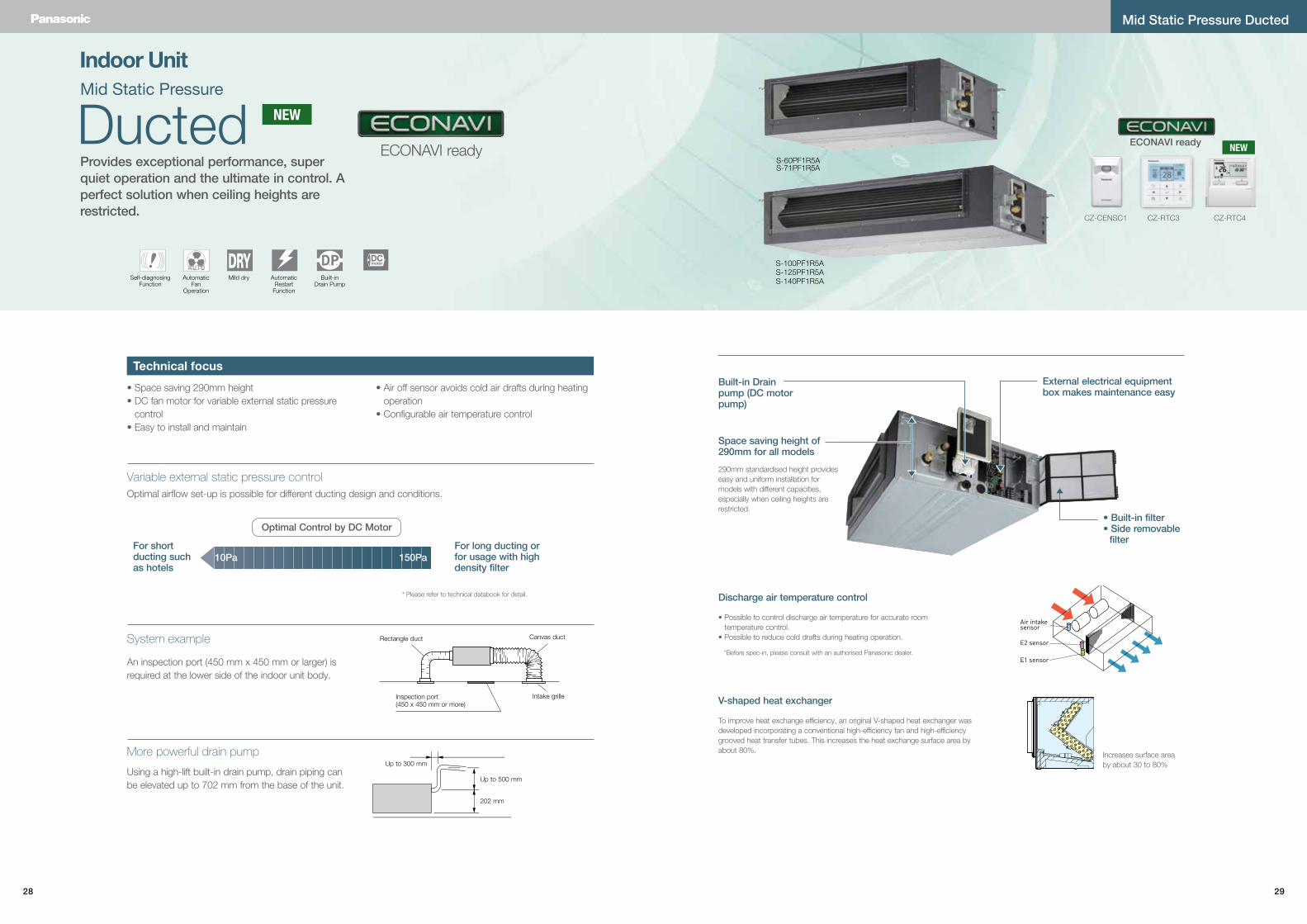
Using a high-lift built-in drain pump, drain piping can be elevated up to 702 mm from the base of the unit.
Optimal airflow set-up is possible for different ducting design and conditions.
An inspection port (450 mm x 450 mm or larger) is required at the lower side of the indoor unit body.
Rectangle duct Canvas duct
Intake grilleInspection port(450 x 450 mm or more)
Built-in Drain pump (DC motor pump)
• Built-in filter• Side removable
filter
Air intake sensor
E2 sensor
E1 sensor
Space saving height of 290mm for all models
290mm standardised height provides easy and uniform installation for models with different capacities, especially when ceiling heights are restricted.
Discharge air temperature control
V-shaped heat exchanger
• Possible to control discharge air temperature for accurate room temperature control.
• Possible to reduce cold drafts during heating operation.
To improve heat exchange efficiency, an original V-shaped heat exchanger was developed incorporating a conventional high-efficiency fan and high-efficiency grooved heat transfer tubes. This increases the heat exchange surface area by about 80%.
*Before spec-in, please consult with an authorised Panasonic dealer.
External electrical equipment box makes maintenance easy
Technical focus
More powerful drain pump
Variable external static pressure control
For short ducting such as hotels
For long ducting or for usage with high density filter
Optimal Control by DC Motor
10Pa 150Pa
* Please refer to technical databook for detail.
Increases surface area by about 30 to 80%
Mid Static Pressure Ducted
Self-diagnosing Function
Automatic Fan
Operation
Mild dry AutomaticRestart
Function
Built-in Drain Pump
DCmotor
NEW
CZ-CENSC1
ECONAVI ready
CZ-RTC3 CZ-RTC4
NEW
30 31
Capacity 6.0KW 7.1KW 10.0KW 12.5KW 14.0KW
Model NameIndoor Unit S-60PF1R5A S-71PF1R5A S-100PF1R5A S-100PF1R5A S-125PF1R5A S-125PF1R5A S-140PF1R5A S-140PF1R5A
Outdoor Unit U-60PE1R5A U-71PE1R5A U-100PE1R5A U-100PE1R8A U-125PE1R5A U-125PE1R5A U-140PE1R5A U-140PE1R8A
Power sourcePhase/Hz 1 Phase/ 50Hz 1 Phase/ 50Hz 1 Phase/ 50Hz 3 Phase/ 50Hz 1 Phase/ 50Hz 3 Phase/ 50Hz 1 Phase/ 50Hz 3 Phase/ 50Hz
V 230V | 240V 230V | 240V 230V | 240V 400V | 415V 230V | 240V 400V | 415V 230V | 240V 400V | 415V
Cooling capacity : Heating capacity
kW 6.0 (2.5 - 7.1)7.0 (2.0 - 8.0)
7.1 (2.5 - 8.0)8.0 (2.0 - 9.0)
10.0 (3.3 - 12.5)11.2 (4.1 - 14.0)
10.0 (3.3 - 12.5)11.2 (4.1 - 14.0)
12.5 (3.3 - 14.0)14.0 (4.1 - 16.0)
12.5 (3.3 - 14.0)14.0 (4.1 - 16.0)
14.0 (3.3 - 15.5)16.0 (4.1 - 18.0)
14.0 (3.3 - 15.5)16.0 (4.1 - 18.0)
BTU/h 20,500 (8,500 - 24,200)23,900 (6,800 - 27,300)
24,200 (8,500 - 27,300)27,300 (6,800 - 30,700)
34,100 (11,300 - 42,700)38,200 (14,000 - 47,800)
34,100 (11,300 - 42,700)38,200 (14,000 - 47,800)
42,700 (11,300 - 47,800)47,800 (14,000 - 54,600)
42,700 (11,300 - 47,800)47,800 (14,000 - 54,600)
47,800 (11,300 - 52,900)54,600 (14,000 - 61,400)
47,800 (11,300 - 52,900)54,600 (14,000 - 61,400)
EER : COP W/W 3.90 : 3.87 3.84 : 3.85 4.10 : 4.31 4.10 : 4.31 3.50 : 4.02 3.50 : 4.02 3.25 : 3.60 3.25 : 3.60
Total power input Cooling : Heating kW 1.54 : 1.81 1.85 : 2.08 2.44 : 2.60 2.44 : 2.60 3.57 : 3.48 3.57 : 3.48 4.31 : 4.44 4.31 : 4.44
Indoor Unit
Current Cooling : Heating A 0.89 : 0.89 | 0.87 : 0.87 0.89 : 0.89 | 0.87 : 0.87 1.30 : 1.34 | 1.27 : 1.29 1.30 : 1.34 | 1.27 : 1.29 1.44 : 1.42 | 1.39 : 1.38 1.44 : 1.42 | 1.39 : 1.38 1.50 :1.50 | 1.47 : 1.46 1.50 :1.50 | 1.47 : 1.46
Dimensions H × W × D mm 290×1,000×700 290×1,000×700 290×1,400×700 290×1,400×700 290×1,400×700 290×1,400×700 290×1,400×700 290×1,400×700
Net weight kg 33 33 45 45 45 45 45 45
Air volume Cooling : Heating L/s 350 : 350 350 : 350 533 : 533 533 : 533 566 : 566 566 : 566 600 : 600 600 : 600
External static pressure Pa 70 (10 - 150) 70 (10 - 150) 100 (10 - 150) 100 (10 - 150) 100 (10 - 150) 100 (10 - 150) 100 (10 - 150) 100 (10 - 150)
Sound pressure level (H/M/L) Cooling : Heating dB(A) 35 / 32 / 26 : 35 / 32 / 26 35 / 32 / 26 : 35 / 32 / 26 38 / 34 / 31 : 38 / 34 / 31 38 / 34 / 31 : 38 / 34 / 31 39 / 35 / 32 : 39 / 35 / 32 39 / 35 / 32 : 39 / 35 / 32 40 / 36 / 33 : 40 / 36 / 33 40 / 36 / 33 : 40 / 36 / 33
Sound power level (H/M/L) Cooling : Heating dB(A) 58 / 55 / 49 : 58 / 55 / 49 58 / 55 / 49 : 58 / 55 / 49 61 / 57 / 54 : 61 / 57 / 54 61 / 57 / 54 : 61 / 57 / 54 62 / 58 / 55 : 62 / 58 / 55 62 / 58 / 55 : 62 / 58 / 55 63 / 59 / 56 : 63 / 59 / 56 63 / 59 / 56 : 63 / 59 / 56
Drain piping mm VP-25 VP-25 VP-25 VP-25 VP-25 VP-25 VP-25 VP-25
Outdoor Unit
Current Cooling : Heating A 7.40 : 7.10 | 8.40 : 8.10 8.60 : 9.50 | 8.30 : 9.20 10.60 : 11.20 | 10.30 : 10.70 3.53 : 3.70 | 3.43 : 3.58 15.90 : 15.80 | 15.30 : 15.10 5.29 : 5.26 | 5.12 : 5.05 19.30 : 19.10 | 18.60 : 18.40 6.42 : 6.35 | 8.18 : 6.15
Dimensions H × W × D mm 996 × 940 × 340 996 × 940 × 340 1,416 × 940 × 340 1,416 × 940 × 340 1,416 × 940 × 340 1,416 × 940 × 340 1,416 × 940 × 340 1,416 × 940 × 340
Net weight kg 68 69 98 98 98 98 98 98
Air volume Cooling : Heating L/s 1,000 : 1,000 1,000 : 1,000 1,833 : 1,583 1,833 : 1,583 2,166 : 1,833 2,166 : 1,833 2,250 : 2,000 2,250 : 2,000
Sound pressure level Cooling : Heating dB(A) 48 : 50 48 : 50 52 : 52 52 : 52 53 : 53 53 : 53 54 : 55 54 : 55
Sound power level Cooling : Heating dB(A) 65 : 67 65 : 67 69 : 69 69 : 69 70 : 70 70 : 70 71 : 71 71 : 71
Piping connections Liquid / Gas m Ø9.52 / Ø15.88 Ø9.52 / Ø15.88 Ø9.52 / Ø15.88 Ø9.52 / Ø15.88 Ø9.52 / Ø15.88 Ø9.52 / Ø15.88 Ø9.52 / Ø15.88 Ø9.52 / Ø15.88
Pipe length min. - max. m 5 - 50 5 - 50 5 - 75 5 - 75 5 - 75 5 - 75 5 - 75 5 - 75
Elevation difference (OU located lower, OU located higher) m 15, 30 15, 30 15, 30 15, 30 15, 30 15, 30 15, 30 15, 30
Maximum chargeless length m 30 30 30 30 30 30 30 30
Refrigerant at shipping, Additional gas amount g R410A 2,000, 50 (g/m) R410A 2,350, 50 (g/m) R410A 3,400, 50 (g/m) R410A 3,400, 50 (g/m) R410A 3,400, 50 (g/m) R410A 3,400, 50 (g/m) R410A 3,400, 50 (g/m) R410A 3,400, 50 (g/m)
Operation ranges Cooling : Heating ˚C -15 to 46 : -20 to 24 -15 to 46 : -20 to 24 -15 to 46 : -20 to 24 -15 to 46 : -20 to 24 -15 to 46 : -20 to 24 -15 to 46 : -20 to 24 -15 to 46 : -20 to 24 -15 to 46 : -20 to 24
Ducted
Mid Static Pressure Ducted
Mid Static Pressure
1000
32
33
32
75
8
30
28
70
0
63
6
150
21 21
8
5(150)
35
70
02
03
02
56
130 70
140 2323
18627
290
2
3
9
1
4
6
11
36
5
30
0
89
26
172
28
0
7
77
27
18
6
(75)54 154
Filter
16-ø3holes
1067(Suspension bolt pitch)
792(Flange O.D.)
150 x 5 = 750
5
8
(150)
717133
150
636
700
758
3028
3232
1400 27
3025
6
130
26
89
300
6511
3
70
6
4
1
9
3
2
290
23
186
231402070
0
35
280
7
172
186
7727
154(75)
54 1192(Flange O.D.)
Filter
20-ø3holes
1467(Suspension bolt pitch)
150 x 7 = 1050
Dimensions: mm
Dimensions: mm
MID STATIC DUCTED Dimensions
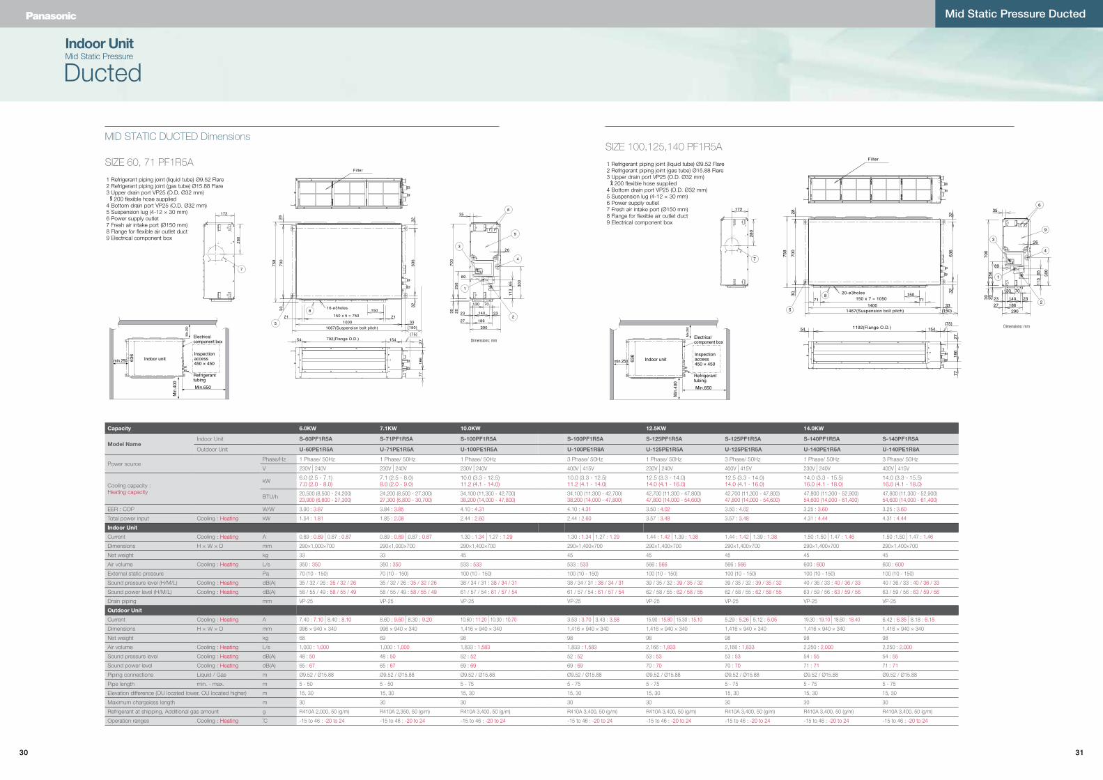
SIZE 60, 71 PF1R5A
SIZE 100,125,140 PF1R5A
1 Refrigerant piping joint (liquid tube) Ø9.52 Flare2 Refrigerant piping joint (gas tube) Ø15.88 Flare3 Upper drain port VP25 (O.D. Ø32 mm)
200 flexible hose supplied4 Bottom drain port VP25 (O.D. Ø32 mm)5 Suspension lug (4-12 × 30 mm)6 Power supply outlet7 Fresh air intake port (Ø150 mm)8 Flange for flexible air outlet duct9 Electrical component box
Indoor Unit
Min.2
50
Electricalcomponent box
Inspectionaccess450 × 450
RefrigeranttubingMin.650
Indoor unit
Min
.400
min.250 636
Min.2
50
Electricalcomponent box
Inspectionaccess450 × 450
RefrigeranttubingMin.650
Indoor unit
Min
.400
min.250 636
32 33
Technical focus
Self-diagnosing Function
Automatic Fan
Operation
Mild dry Intelligent Auto Swing
AutomaticRestart
Function
Auto Swing(Auto Flap Control)
Built-in Drain Pump
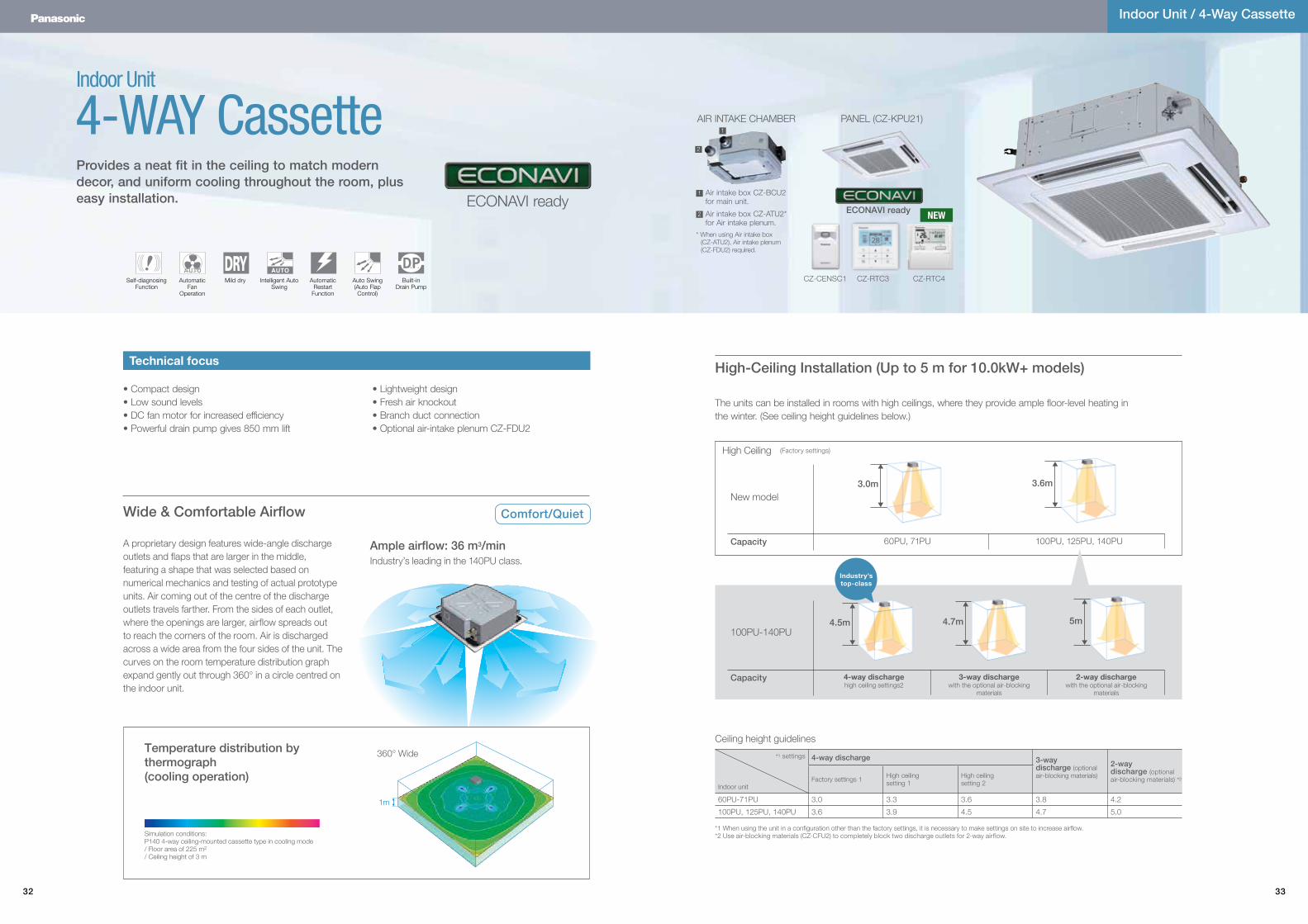
Provides a neat fit in the ceiling to match modern decor, and uniform cooling throughout the room, plus easy installation.
Comfort/QuietWide & Comfortable Airflow
Temperature distribution by thermograph (cooling operation)
Simulation conditions: P140 4-way ceiling-mounted cassette type in cooling mode/ Floor area of 225 m2
/ Ceiling height of 3 m
A proprietary design features wide-angle discharge outlets and flaps that are larger in the middle, featuring a shape that was selected based on numerical mechanics and testing of actual prototype units. Air coming out of the centre of the discharge outlets travels farther. From the sides of each outlet, where the openings are larger, airflow spreads out to reach the corners of the room. Air is discharged across a wide area from the four sides of the unit. The curves on the room temperature distribution graph expand gently out through 360° in a circle centred on the indoor unit.
Ample airflow: 36 m3/minIndustry’s leading in the 140PU class.
High-Ceiling Installation (Up to 5 m for 10.0kW+ models)
60PU, 71PU 100PU, 125PU, 140PU
(Factory settings)
4-way dischargehigh ceiling settings2
3-way dischargewith the optional air-blocking
materials
2-way dischargewith the optional air-blocking
materials
100PU-140PU
*1 When using the unit in a configuration other than the factory settings, it is necessary to make settings on site to increase airflow. *2 Use air-blocking materials (CZ-CFU2) to completely block two discharge outlets for 2-way airflow.
Ceiling height guidelines
*1 settings
Indoor unit
4-way discharge 3-way discharge (optional air-blocking materials)
2-way discharge (optional air-blocking materials) *2Factory settings 1 High ceiling
setting 1High ceiling setting 2
60PU-71PU 3.0 3.3 3.6 3.8 4.2
100PU, 125PU, 140PU 3.6 3.9 4.5 4.7 5.0
The units can be installed in rooms with high ceilings, where they provide ample floor-level heating in the winter. (See ceiling height guidelines below.)
High Ceiling
New model
Capacity
Capacity
4-WAY Cassette
Indoor Unit / 4-Way Cassette
Indoor Unit
• Compact design• Low sound levels• DC fan motor for increased efficiency• Powerful drain pump gives 850 mm lift
• Lightweight design• Fresh air knockout• Branch duct connection• Optional air-intake plenum CZ-FDU2
1m
360° Wide
5m
3.6m
4.7m
3.0m
4.5m
Industry’s top-class
PANEL (CZ-KPU21)AIR INTAKE CHAMBER
Air intake box CZ-BCU2 for main unit.
Air intake box CZ-ATU2* for Air intake plenum.
* When using Air intake box (CZ-ATU2), Air intake plenum (CZ-FDU2) required.
1
1
2
2
ECONAVI ready
CZ-CENSC1
ECONAVI ready
CZ-RTC3 CZ-RTC4
NEW
34 35
AX
X view
60PU-71PU 100PU-140PU256 319124 187
840480
180 B
160
421
(411
)
130 167
B
480
82 160
160
118
18
30
130
95
95
115
80
80
115
167
2
345
840
514950
515
950
271 50
5033
.512
142
145
Less than 300
Less
than
670
Less
than
850
ø162
ø113
B
8
5 3 4
7
77 6 9 7
2
2
2
2
1
860~910(Ceiling opening dimension)
860~
910
(Cei
ling
open
ing
dim
ensio
n)
786(Suspension bolt pitch)
745
(Sus
pens
ion bo
lt pitc
h)
Less than 35 Less than 35
Burring hole 4 - ø3
Burring hole 4 - ø3
Air discharge duct connection hole (ø150)
Air intake duct connection hole (ø100)Drain up
A
The flap can be removed easily for cleaning.
Easy Maintenance and Cleaning
Only 256 mm
Drain Pump of about 850 mm from the ceiling surface
Up to 300 mm
Up to 850 mm
A lightweight unit at 24 kg, the unit is also very slim with a height of only 256 mm, making installation possible even in narrow ceilings.
The drain height can be increased by approximately 350 mm over the conventional value by using a high-lift drain pump, and long horizontal piping is possible.
Lighter and Slimmer, Easier Installation
A Drain Height of Approx. 850 mm from the Ceiling Surface
Low-Profile 33.5 mm PanelThe square panel integrates seamlessly with the ceiling. Discharge outlets close when the unit is stopped. Protrusion of 33.5 mm
One of the industry’s thinnest panels
Indoor Unit
4-way Cassette
Indoor Unit / 4-Way Cassette
Capacity 6.0kW 7.1kW 10.0kW 12.5kW 14.0kW
Model Name
Indoor Unit S-60PU1R5A S-71PU1R5A S-100PU1R5A S-100PU1R5A S-125PU1R5A S-125PU1R5 A S-140PU1R5A S-140PU1R5A
Outdoor Unit U-60PE1R5A U-71PE1R5A U-100PE1R5A U-100PE1R8A U-125PE1R5A U-125PE1R8A U-140PE1R5A U-140PE1R8A
Panel CZ-KPU21 CZ-KPU21 CZ-KPU21 CZ-KPU21 CZ-KPU21 CZ-KPU21 CZ-KPU21 CZ-KPU21
Power sourcePhase/Hz 1 phase, 50Hz 1 phase, 50Hz 1 phase, 50Hz 3 phase, 50Hz 1 phase, 50Hz 3 phase, 50Hz 1 phase, 50Hz 3 phase, 50Hz
V 230V | 240V 230V | 240V 230V | 240V 400V | 415V 230V | 240V 400V | 415V 230V | 240V 400V | 415V
Cooling capacityHeating capacity
kW 6.0 (2.5 - 8.0)7.0 (2.0 - 8.5)
7.1 (2.5 - 8.2)8.0 (2.0 - 9.0)
10.0 (3.3 - 12.5)11.2 (4.1 - 14.0)
10.0 (3.3 - 12.5)11.2 (4.1 - 14.0)
12.5 (3.3 - 14.0)14.0 (4.1 - 16.0)
12.5 (3.3 - 14.0)14.0 (4.1 - 16.0)
14.0 (3.3 - 15.5)16.0 (4.1 - 18.0)
14.0 (3.3 - 15.5)16.0 (4.1 - 18.0)
BTU/h 20,500 (8,500 - 27,300)23,900 (6,800 - 29,000)
24,200 (8,500 - 28,000)27,300 (6,800 - 30,700)
34,100 (11,300 - 42,700)38,200 (14,000 - 47,800)
34,100 (11,300 - 42,700)38,200 (14,000 - 47,800)
42,700 (11,300 - 47,800)47,800 (14,000 - 54,600)
42,700 (11,300 - 47,800)47,800 (14,000 - 54,600)
47,800 (11,300 - 52,900)54,600 (14,000 - 61,400)
47,800 (11,300 - 52,900)54,600 (14,000 - 61,400)
EER : COP Cooling : Heating W/W 4.05 : 3.87 3.94 : 4.00 4.20 : 4.31 4.20 : 4.31 3.60 : 4.00 3.60 : 4.00 3.25 : 3.70 3.25 : 3.70
Total power input Cooling : Heating kW 1.48 : 1.81 1.80 : 2.00 2.38 : 2.60 2.38 : 2.60 3.47 : 3.50 3.47 : 3.50 4.31 : 4.33 4.31 : 4.33
Indoor Unit
Current Cooling : Heating A 0.31 : 0.30 | 0.30 : 0.29 0.33 : 0.32 | 0.32 : 0.31 0.71 : 0.65 | 0.71 : 0.64 0.71 : 0.65 | 0.71 : 0.64 0.76 : 0.73 | 0.73 : 0.73 0.76 : 0.73 | 0.73 : 0.73 0.89 : 0.80 | 0.87 : 0.79 0.89 : 0.80 | 0.87 : 0.79
Dimensions H × W × D Indoor mm 256 × 840 × 840 256 × 840 × 840 319 × 840 × 840 319 × 840 × 840 319 × 840 × 840 319 × 840 × 840 319 × 840 × 840 319 × 840 × 840
Panel mm 33.5 x 950 x 950 33.5 x 950 x 950 33.5 x 950 x 950 33.5 x 950 x 950 33.5 x 950 x 950 33.5 x 950 x 950 33.5 x 950 x 950 33.5 x 950 x 950
Net weight Indoor kg 24 24 27 27 27 27 27 27
Panel kg 4 4 4 4 4 4 4 4
Air volume Cooling : Heating L/s 350 : 350 366 : 366 550 : 550 550 : 550 583 : 583 583 : 583 600 : 600 600 : 600
Sound pressure level (H/M/L) Cooling : Heating dB(A) 36 / 31 / 28 : 36 / 31 / 28 37 / 31 / 28 : 37 / 31 / 28 44 / 38 / 32 : 44 / 38 / 32 44 / 38 / 32 : 44 / 38 / 32 45 / 39 / 33 : 45 / 39 / 33 45 / 39 / 33 : 45 / 39 / 33 46 / 40 / 34 : 46 / 40 / 34 46 / 40 / 34 : 46 / 40 / 34
Sound power level (H/M/L) Cooling : Heating dB(A) 53 / 48 / 45 : 53 / 48 / 45 54 / 48 / 45 : 54 / 48 / 45 62 / 55 / 49 : 62 / 55 / 49 62 / 55 / 49 : 62 / 55 / 49 63 / 56 / 50 : 63 / 56 / 50 63 / 56 / 50 : 63 / 56 / 50 64 / 57 / 51 : 64 / 57 / 51 64 / 57 / 51 : 64 / 57 / 51
Number of fan speed 3 3 3 3 3 3 3 3
Drain pipe size mm VP-25 VP-25 VP-25 VP-25 VP-25 VP-25 VP-25 VP-25
Outdoor Unit
Current Cooling : Heating A 6.90 : 8.20 | 6.70 : 7.95 8.10 : 9.00 | 7.90 : 8.70 10.3 : 11.4 | 9.90 : 11.0 3.50 : 3.85 | 3.40 : 3.75 15.3 : 15.4 | 14.8 : 14.9 5.15 : 5.20 | 5.00 : 5.05 19.0 : 19.2 | 18.4 : 18.6 6.45 : 6.50 | 6.20 : 6.25
Dimensions H × W × D mm 996 × 940 × 340 996 × 940 × 340 1,416 × 940 × 340 1,416 × 940 × 340 1,416 × 940 × 340 1,416 × 940 × 340 1,416 × 940 × 340 1,416 × 940 × 340
Net weight kg 68 69 98 98 98 98 98 98
Air volume Cooling : Heating L/s 1,000 : 1,000 1,000 : 1,000 1,833 : 1,583 1,833 : 1,583 2,166 : 1,833 2,166 : 1,833 2,250 : 2,000 2,250 : 2,000
Sound pressure level (Silent mode) Cooling : Heating dB(A) 48 (46) : 50 (48) 48 (46) : 50 (48) 52 (50) : 52 (50) 52 (50) : 52 (50) 53 (51) : 53 (51) 53 (51) : 53 (51) 54 (52) : 55 (53) 54 (52) : 55 (53)
Sound power level (Silent mode) Cooling : Heating dB(A) 65 (63) : 67 (65) 65 (63) : 67 (65) 69 (67) : 69 (67) 69 (67) : 69 (67) 70 (68) : 70 (68) 70 (68) : 70 (68) 71 (69) : 71 (69) 71 (69) : 71 (69)
Piping connections m Ø9.52 / Ø15.88 Ø9.52 / Ø15.88 Ø9.52 / Ø15.88 Ø9.52 / Ø15.88 Ø9.52 / Ø15.88 Ø9.52 / Ø15.88 Ø9.52 / Ø15.88 Ø9.52 / Ø15.88
Pipe length min. - max. m 5 - 50 5 - 50 5 - 75 5 - 75 5 - 75 5 - 75 5 - 75 5 - 75
Elevation difference (OU located lower, OU located higher) m 15, 30 15, 30 15, 30 15, 30 15, 30 15, 30 15, 30 15, 30
Maximum chargeless length m 30 30 30 30 30 30 30 30
Refrigerant at shipping, Additional gas amount g R410A 2,000, 50 (g/m) R410A 2,350, 50 (g/m) R410A 3,400, 50 (g/m) R410A 3,400, 50 (g/m) R410A 3,400, 50 (g/m) R410A 3,400, 50 (g/m) R410A 3,400, 50 (g/m) R410A 3,400, 50 (g/m)
Operation ranges Cooling : Heating ˚C -15 - 46 : -20 - 24 -15 - 46 : -20 - 24 -15 - 46 : -20 - 24 -15 - 46 : -20 - 24 -15 - 46 : -20 - 24 -15 - 46 : -20 - 24 -15 - 46 : -20 - 24 -15 - 46 : -20 - 24
* Adjust the suspension bolt length so that the gap from the lower ceiling surface becomes 30 mm or more (18 mm or more from the lower surface of the body) as shown in the figure. When the suspension bolt length is long, it hits the ceiling panel and installation is not possible.
Dimensions: mm
*1: Air inlet kit is necessary. Filter size: 520 x 520 x 16
* For 6.0kW/7.1kW
Dimensions1 Air intake grill2 Air discharge outlet3 Refrigerant piping (liquid pipes) : ø9.52 (flared)4 Refrigerant piping (gas pipes) : ø15.88 (flared)5 Drain outlet VP25(outer ø32)6 Power supply port7 Discharge duct (ø150)8 Suspension bolt hole (4-12x30 slot)9 Fresh air intake duct connection port (ø100)*1
It is easy to remove the washable flaps by hand.
Suction grill able to make 90 degree turns.
Simplified remote controllerCZ-RE2C2
Wireless remote controllerCZ-RWSU2N
Timer remote controllerCZ-RTC4
Optional Controller
Deluxe Wired remote controllerCZ-RTC3
ECONAVI sensorCZ-CENSC1
NEW
36 37
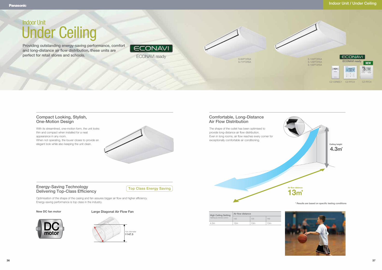
13m
4.3m
Indoor Unit
Under Ceiling
Energy-Saving Technology Delivering Top-Class Efficiency
Compact Looking, Stylish, One-Motion Design
Optimisation of the shape of the casing and fan assures bigger air flow and higher efficiency.Energy-saving performance is top class in the industry.
With its streamlined, one-motion form, the unit looks thin and compact when installed for a neat appearance in any room.When not operating, the louver closes to provide an elegant look while also keeping the unit clean.
The shape of the outlet has been optimised to provide long-distance air flow distribution. Even in long rooms, air flow reaches every corner for exceptionally comfortable air conditioning.
Providing outstanding energy-saving performance, comfort and long-distance air flow distribution, these units areperfect for retail stores and schools.
Comfortable, Long-Distance Air Flow Distribution
Indoor Unit / Under Ceiling
High Ceiling Setting*Setting by remote control
Air flow distance
100 125 140
4.3m 12m 13m 13m
Top Class Energy Saving
New DC fan motor Large Diagonal Air Flow Fan
Air flow distance
Ceiling height
*
*
* Results are based on specific testing conditions
S-60PT2R5AS-71PT2R5A
S-100PT2R5AS-125PT2R5AS-140PT2R5A
DCmotor Fan diameter
147.5φ
ECONAVI ready
CZ-CENSC1
ECONAVI ready
CZ-RTC3 CZ-RTC4
NEW
38 39
Capacity 6.0kW 7.1kW 10.0kW 12.0kW 14.0kW
Model NameIndoor Unit S-60PT2R5A S-71PT2R5A S-100PT2R5A S-100PT2R5A S-125PT2R5A S-125PT2R5A S-140PT2R5A S-140PT2R5A
Outdoor Unit U-60PE1R5A U-71PE1R5A U-100PE1R5A U-100PE1R8A U-125PE1R5A U-125PE1R8A U-140PE1R5A U-140PE1R8A
Power sourcePhase/Hz 1 Phase/ 50Hz 1 Phase/ 50Hz 1 Phase/ 50Hz 3-Phase/ 50Hz 1 Phase/ 50Hz 3-Phase/ 50Hz 1 Phase/ 50Hz 3-Phase/ 50Hz
V 230V | 240V 230V | 240V 230V | 240V 400V | 415V 230V | 240V 400V | 415V 230V | 240V 400V | 415V
Cooling capacity : Heating capacity
kW 6.0 (2.5 - 7.1)7.0 (2.0 - 8.0)
7.1 (2.5 - 8.0)8.0 (2.0 - 9.0)
10.0 (3.3 - 12.5)11.2 (4.1 - 14.0)
10.0 (3.3 - 12.5)11.2 (4.1 - 14.0)
12.5 (3.3 - 14.0)14.0 (4.1 - 16.0)
12.5 (3.3 - 14.0)14.0 (4.1 - 16.0)
14.0 (3.3 - 15.0)16.0 (4.1 - 18.0)
14.0 (3.3 - 15.0)16.0 (4.1 - 18.0)
BTU/h 20,500 (8,500 - 24,200)23,900 (6,800 - 27,300)
24,200 (8,500 - 27,300)27,300 (6,800 - 30,700)
34,100 (11,300 - 42,700)38,200 (14,000 - 47,800)
34,100 (11,300 - 42,700)38,200 (14,000 - 47,800)
42,700 (11,300 - 47,800)47,800 (14,000 - 54,600)
42,700 (11,300 - 47,800)47,800 (14,000 - 54,600)
47,800 (11,300 - 51,200)54,600 (14,000 - 61,400)
47,800 (11,300 - 51,200)54,600 (14,000 - 61,400)
EER : COP W/W 4.03 : 4.02 3.68 : 4.15 3.95 : 4.31 3.95 : 4.31 3.35 : 3.99 3.35 : 3.99 3.01 : 3.67 3.01 : 3.67
Total power input Cooling : Heating kW 1.49 : 1.74 1.93 : 1.93 2.53 : 2.60 2.53 : 2.60 3.73 : 3.51 3.73 : 3.51 4.65 : 4.36 4.65 : 4.36
Indoor Unit
Current Cooling : Heating A 0.41 : 0.41 | 0.40 : 0.40 0.44 : 0.44 | 0.43 : 0.43 0.67 : 0.67 | 0.65 : 0.65 0.67 : 0.67 | 0.65 : 0.65 0.86 : 0.86 | 0.83 : 0.83 0.86 : 0.86 | 0.83 : 0.83 0.91 : 0.91 | 0.88 : 0.88 0.91 : 0.91 | 0.88 : 0.88
Dimensions H × W × D mm 235×1,275×690 235×1,275×690 235×1,590×690 235×1,590×690 235×1,590×690 235×1,590×690 235×1,590×690 235×1,590×690
Net weight kg 33 33 40 40 40 40 40 40
Air volume Cooling : Heating L/s 333 : 333 350 : 350 500 : 500 500 : 500 566 : 566 566 : 566 583 : 583 583 : 583
External static pressure Pa - - - - - - - -
Sound pressure level (H/M/L) Cooling : Heating dB(A) 38 / 34 / 30 : 38 / 34 / 30 39 / 35 / 31 : 39 / 35 / 31 42 / 37 / 35 : 42 / 37 / 35 42 / 37 / 35 : 42 / 37 / 35 46 / 40 / 36 : 46 / 40 / 36 46 / 40 / 36 : 46 / 40 / 36 47 / 41 / 37 : 47 / 41 / 37 47 / 41 / 37 : 47 / 41 / 37
Sound power level (H/M/L) Cooling : Heating dB(A) 56 / 52 / 48 : 56 / 52 / 48 57 / 53 / 49 : 57 / 53 / 49 60 / 55 / 53 : 60 / 55 / 53 60 / 55 / 53 : 60 / 55 / 53 64 / 58 / 54 : 64 / 58 / 54 64 / 58 / 54 : 64 / 58 / 54 65 / 59 / 55 : 65 / 59 / 55 65 / 59 / 55 : 65 / 59 / 55
Number of fan speed 3 3 3 3 3 3 3 3
Drain pipe size mm VP-20 VP-20 VP-20 VP-20 VP-20 VP-20 VP-20 VP-20
Outdoor Unit
Current Cooling : Heating A 6.90 : 7.80 | 6.70 : 7.60 8.70 : 8.60 | 8.40 : 8.30 11.1 : 11.4 | 10.6 : 11.0 3.75 : 3.85 | 3.65 : 3.75 16.4 : 15.4 | 15.8 : 14.9 5.55 : 5.20 | 5.35 : 5.05 20.5 : 19.2 | 19.8 : 18.5 6.95 : 6.50 | 6.70 : 6.25
Dimensions H × W × D mm 996 × 940 × 340 996 × 940 × 340 1,416 × 940 × 340 1,416 × 940 × 340 1,416 × 940 × 340 1,416 × 940 × 340 1,416 × 940 × 340 1,416 × 940 × 340
Net weight kg 68 69 98 98 98 98 98 98
Air volume Cooling : Heating L/s 1,000: 1,000 1,000: 1,000 1,833: 1,583 1,833: 1,583 2,166: 1,833 2,166: 1,833 2,250: 2,000 2,250: 2,000
Sound pressure level Cooling : Heating dB(A) 48 : 50 48 : 50 52 : 52 52 : 52 53 : 53 53 : 53 54 : 55 54 : 55
Sound power level Cooling : Heating dB(A) 65 : 67 65 : 67 69 : 69 69 : 69 70 : 70 70 : 70 71 : 71 71 : 71
Piping connections Liquid/Gas m Ø9.52 / Ø15.88 Ø9.52 / Ø15.88 Ø9.52 / Ø15.88 Ø9.52 / Ø15.88 Ø9.52 / Ø15.88 Ø9.52 / Ø15.88 Ø9.52 / Ø15.88 Ø9.52 / Ø15.88
Pipe length min. - max. m 5 - 50 5 - 50 5 - 75 5 - 75 5 - 75 5 - 75 5 - 75 5 - 75
Elevation difference (OU located lower, OU located higher) m 15, 30 15, 30 15, 30 15, 30 15, 30 15, 30 15, 30 15, 30
Maximum chargeless length m 30 30 30 30 30 30 30 30
Refrigerant at shipping, Additional gas amount g R410A 2,000, 50 (g/m) R410A 2,350, 50 (g/m) R410A 3,400, 50 (g/m) R410A 3,400, 50 (g/m) R410A 3,400, 50 (g/m) R410A 3,400, 50 (g/m) R410A 3,400, 50 (g/m) R410A 3,400, 50 (g/m)
Operation ranges Cooling : Heating ˚C -15 to 46 : -20 to 24 -15 to 46 : -20 to 24 -15 to 46 : -20 to 24 -15 to 46 : -20 to 24 -15 to 46 : -20 to 24 -15 to 46 : -20 to 24 -15 to 46 : -20 to 24 -15 to 46 : -20 to 24
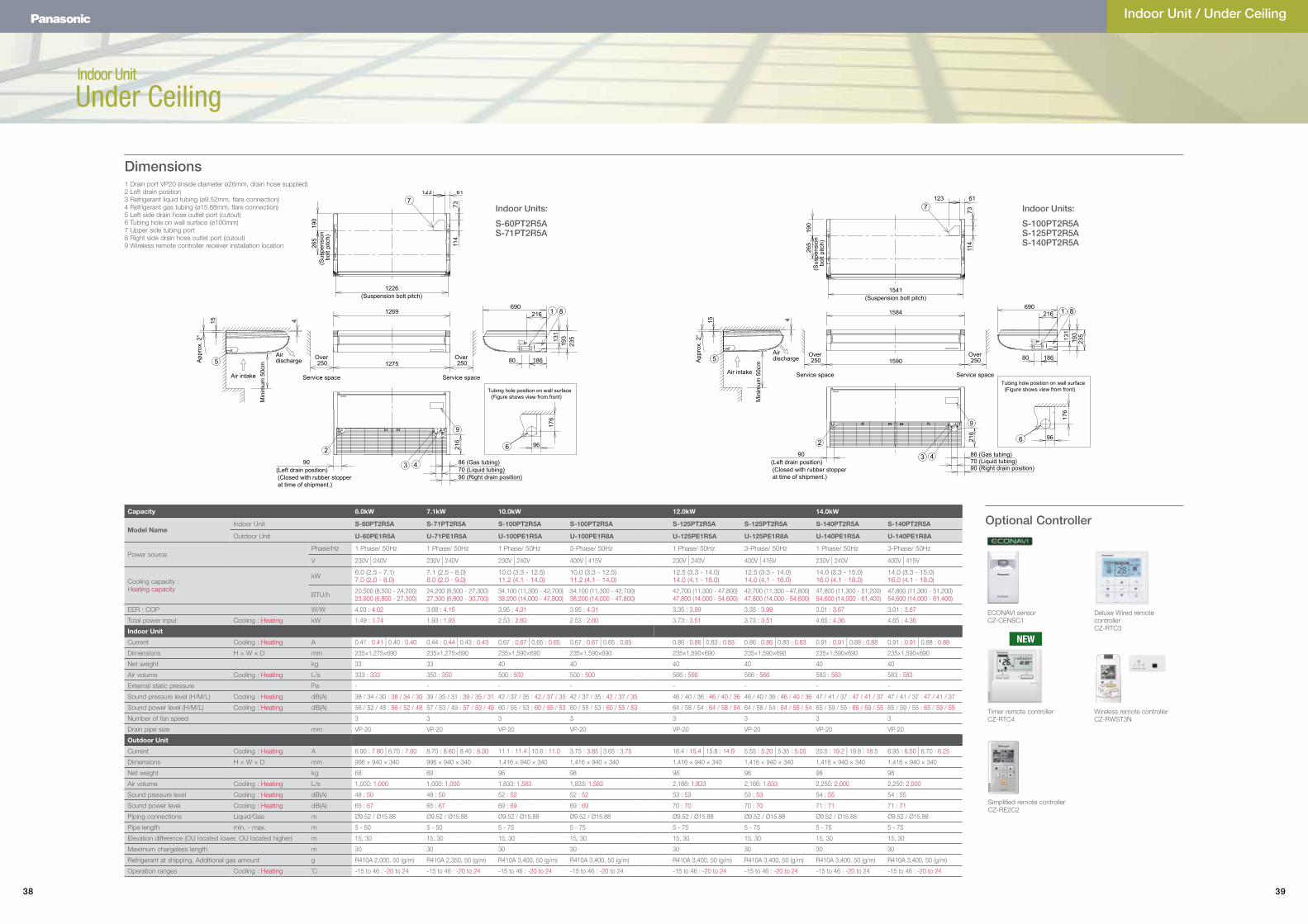
Dimensions
Indoor Units:
S-60PT2R5AS-71PT2R5A
Indoor Units:
S-100PT2R5AS-125PT2R5AS-140PT2R5A
Indoor Unit
Under Ceiling
Optional Controller
Indoor Unit / Under Ceiling
1 Drain port VP20 (inside diameter ø26mm, drain hose supplied)2 Left drain position3 Refrigerant liquid tubing (ø9.52mm, flare connection)4 Refrigerant gas tubing (ø15.88mm, flare connection)5 Left side drain hose outlet port (cutout)6 Tubing hole on wall surface (ø100mm)7 Upper side tubing port8 Right side drain hose outlet port (cutout)9 Wireless remote controller receiver installation location
Simplified remote controllerCZ-RE2C2
Wireless remote controllerCZ-RWST3N
Timer remote controllerCZ-RTC4
Deluxe Wired remote controllerCZ-RTC3
ECONAVI sensorCZ-CENSC1
Air intake
Air discharge
Min
imum
50c
m
(Suspension bolt pitch)1541
(Sus
pens
ion
bolt
pitc
h)
App
rox.
2°
90 (Right drain position)70 (Liquid tubing)86 (Gas tubing)
(Closed with rubber stopper at time of shipment.)
(Left drain position)90
9
Service space
Over 250
Service space
Over 2501590
1584
7
190
265
7311
4
123 61
1 8
235
193
131
80
216
186
690
5
15 4
43
2 216
6
176
96
Tubing hole position on wall surface (Figure shows view from front)
(Suspension bolt pitch)1226
(Sus
pens
ion
bolt
pitc
h)
Air intake Service space
Over 250
Service space
Over 250A
ppro
x. 2
°
Air discharge
Min
imum
50c
m
90 (Right drain position)70 (Liquid tubing)86 (Gas tubing)
(Closed with rubber stopper at time of shipment.)
(Left drain position)90
9
1275
1269
7
190
265
7311
4
123 61
1 8690
216
18680
131
193
235
5
415
43
2 216
6
176
96
Tubing hole position on wall surface (Figure shows view from front)
NEW
40 41
OPERATION SYSTEM INDIVIDUAL CONTROL SYSTEMS TIMER OPERATION CENTRALISED CONTROL SYSTEMS
Requirements High-spec operation Normal operation Operation from anywhere in the room Quick and easy operation Daily and weekly program Operation with various function
from centre stationOnly ON/OFF operation from centre station
Simplified load distribution ratio (LDR) for each tenant
BMS SystemPC Base
Connection with3rd Party Controller
Touch screen panel
External appearance
Type, model name
Deluxe WiredRemote Controller
Timer Remote Controller (Wired)
Wireless Remote Controller Simplified Remote Controller Schedule Timer System Controller ON/OFF Controller Intelligent Controller
CZ-RTC3 CZ-RTC4 CZ-RWSU2NCZ-RWST3N
C-RWSK2 + CZ-RWSC3 CZ-RE2C2 CZ-ESWC2 CZ-64ESMC2 CZ-ANC2 CZ-256ESMC2
(CZ-CFUNC2)
Built-in thermostat l l l l — — — —ECONAVI on/off control l l — — — — — —
Number of indoor units which can be controlled 1 group, 8 units 1 group, 8 units 1 group, 8 units 1 group, 8 units 64 groups, max. 64 units 64 groups, max. 64 units 16 groups, max. 64 units 64 units x 4 links, max. 256
units
Use limitations
· Up to 2 controllers can be connected per group (When using ECONAVI sensor, only one remote controller is possible to connect at indoor unit)
· Up to 2 controllers can be connected per group. (When using ECONAVI sensor, only one remote controller is possible to connect at indoor unit)
· Up to 2 controllers can be connected per group.
· Up to 2 controllers can be connected per group.
· Required power supply from the system controller
· When there is no system controller, connection is possible to the T10 terminal of an indoor unit.
· Up to 10 controllers, can be connected to one system.
· Main unit/sub unit (1 main unit + 1 sub unit) connection is possible.
· Use without remote controller is possible.
· Up to 8 controllers (4 main units + 4 sub units) can be connected to one system.
· Use without remote controller is impossible.
· A communication adaptor (CZ-CFUNC2) must be installed for three or more links.
Function ON/OFF l l l l — l l l
Mode setting l l l l — l — l
Fan speed setting l l l l — l — l
Temperature setting l l l l — l — l
Air flow direction l l l l — l¹ — l¹Permit/Prohibit switching l — — — — l l l
Weekly program l l — — l — — l
ControllersA wide variety of control options to meet the requirements of different applications.
Interface adaptor
Seri-Para I/O unit for each indoor unit
Communication Adaptor
Web Interface Systems
Optional software
CZ-CSWKC2
CZ-CWEBC2
*PC required (field supply)
*PC required (field supply)
CZ-CSWAC2 for Load distribution
CZ-CSWWC2 for Web application
CZ-CSWGC2 for Object layout display
CZ-CSWBC2 for BACnet software
interface
CZ-CAPDC2
LonWorks Interface
CZ-CAPC2
CZ-CAPBC2
CZ-CFUNC2
CZ-CLNC2
Seri-Para I/O unit for outdoor unit
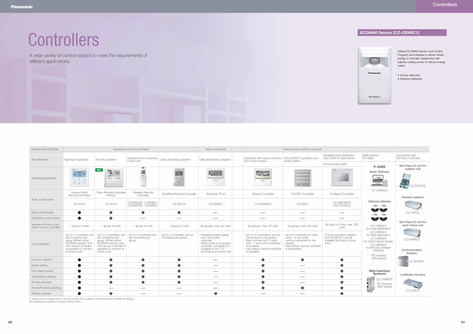
P-AIMSBasic Software
Utilises ECONAVI Sensor and Control Program technologies to detect where energy is normally wasted and self-adjusts cooling power to reduce energy waste.
ECONAVI Sensor [CZ-CENSC1]
1. Setting is not possible when a remote control unit is present. (Use the remote controller for setting.)All specifications subject to change without notice.
• Activity detection• Absence detection
Controllers
NEW
42 43
Controllers
Control contents Part name, model No. Quantity
Standard Control• Control of the various operations of the indoor unit
by wired or wireless remote controller.• Cooling or heating mode of the outdoor unit is
decided by the first priority of the remote controller.
• Switching between remote controller sensor and body sensor is possible.
Timer remote controllerCZ-RTC4 / CZ-RTC3Simplified remote controllerCZ-RE2C2Wireless remote controllerCZ-RWSU2N / CZ-RWST3N / CZ-RWSK2 + CZ-RWSC3
1 unit each
(1) Group control• Batch remote control on all indoor units.• Operation of all indoor cells in the same mode.• Up to 8 units can be connected.• The sensor is the body sensor, and thermostat
ON/OFF setting in regard to the temperature set by the remote controller is possible for each indoor unit.
Timer remote controllerCZ-RTC4 / CZ-RTC3Simplified remote controllerCZ-RE2C2Wireless remote controllerCZ-RWSU2N / CZ-RWST3N / CZ-RWSK2 + CZ-RWSC3
As required
(2) Main/sub remote control• Max 2 remote controllers per indoor unit. (Main
remote controller can be connected)• The button pressed last has priority.• Timer setting is possible even with the sub remote
controller. When using ECONAVI sensor, only one remote controller is possible to connect at indoor unit.
Main or subTimer remote controllerCZ-RTC4 / CZ-RTC3Simplified remote controllerCZ-RE2C2Wireless remote controllerCZ-RWSU2N / CZ-RWST3N / CZ-RWSK2 + CZ-RWSC3
As required
Individual Control Systems
SYSTEM EXAMPLE
Remote controller
Standard control
(2) Main/subremote control
(1) Group control
Main MainSub Sub
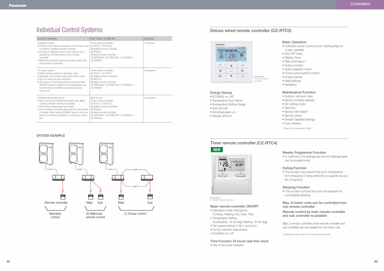
Deluxe wired remote controller (CZ-RTC3)
Basic Operation• Individual Louver Control (Lock individual flap for 4-way cassette)• ON/ OFF timer• Weekly Timer• Filter information*• Outing function• Quiet operation mode*• Power consumption monitor*• Energy saving*• Initial settings• Ventilation
Maintenance Function• Outdoor unit error data• Service Contact address• RC setting mode• Test Run• Sensor Information*• Service check• Simple/ Detailed Settings• Auto address
Energy Saving• ECONAVI on/ off*• Temperature Auto Return• Temperature Setting Range• Auto Shutoff• Schedule peak cut• Repeat off timer
DimensionsH 120 x W 120 x D 16 mm
* Subject to the connected model
NEWTimer remote controller (CZ-RTC4)
Basic remote controller ON/OFF• Operation mode changeover (Cooling, Heating, Dry, Auto, Fan).• Temperature setting (Cooling/Dry: 18-30 deg Heating: 16-30 deg).• Fan speed setting H/ M/ L and Auto.• Air flow direction adjustment.• ECONAVI on/ off*
Time Function 24 hours real time clock• Day of the week indicator.
Weekly Programme Function• A maximum of 6 settings/day and 42 settings/week
can be programmed.
Outing Function• This function can prevent the room temperature
from dropping or rising when the occupants are out for a long time.
Sleeping Function• This function controls the room temperature for
comfortable sleeping.
Max. 8 indoor units can be controlled from one remote controller
Remote control by main remote controller and sub controller is possible
Max. 2 remote controllers (main remote controller and sub controller) can be installed for one indoor unit.
DimensionsH 120 x W 120 x D 20 mm
* Depending on the model, some menus cannot be used.
44 45
Simplified remote controller (CZ-RE2C2)
Wireless remote controller
A remote controller with simple functions and basic operation
• Suitable for open rooms or hotels where detailed functions are not required.• ON/OFF, operation mode switching, temperature setting, wind velocity switching,
wind direction setting, alarm display, and remote controller self-diagnosis can be performed.
• Batch group control for up to 8 indoor units.• Remote control by main remote controller and sub controller is possible with a
simplified remote controller or a wired remote controller (up to two units).
Remote control by main remote controller and sub controller is possible• Max. 2 remote controllers (main remote controller and sub controller) can be
installed for one indoor unit.
When CZ-RWSC3 is used, wireless control becomes possible for all indoor units• When a separate receiver is set up in a different room, control from that room
also becomes possible.• Automatic operation by means of the emergency operation button is possible
even when the remote controller has been lost or the batteries have been exhausted.
In addition, there are other functions such as temperature setting, operation switching, wind direction/fan speed setting, etc
Ventilation independent operation is possibleWhen commercial ventilation fans or heat-exchange ventilation fans have been installed, they can be operated with this remote control (interlocked operation with the indoor unit or independent ventilation ON/OFF).
DimensionsH 120 x W 70 x D 17 mm
For 4-Way cassette typeCZ-RWSU2N
For all Ducted typesCZ-RWSK2 + CZ-RWSC3
For under ceiling typeCZ-RWST3N
Controllers
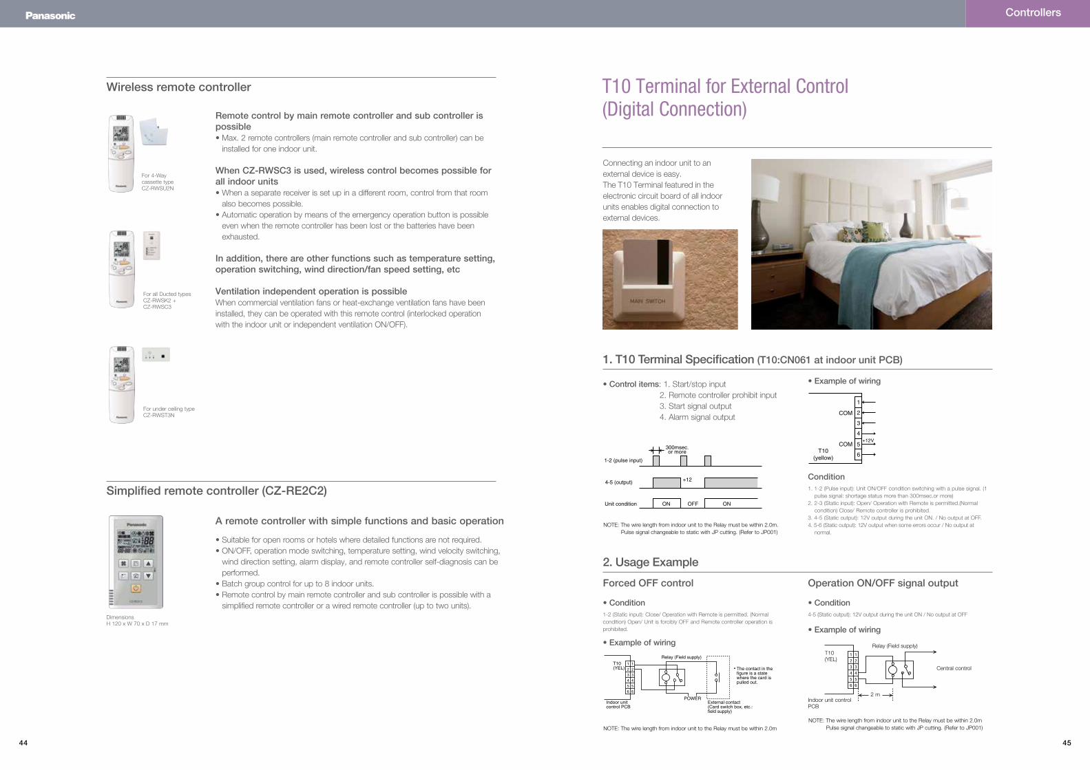
T10 Terminal for External Control (Digital Connection)
Connecting an indoor unit to an external device is easy. The T10 Terminal featured in the electronic circuit board of all indoor units enables digital connection to external devices.
NOTE: The wire length from indoor unit to the Relay must be within 2.0m. Pulse signal changeable to static with JP cutting. (Refer to JP001)
NOTE: The wire length from indoor unit to the Relay must be within 2.0m
Central control
• Example of wiring
• Example of wiring
4-5 (Static output): 12V output during the unit ON / No output at OFF
1. 1-2 (Pulse input): Unit ON/OFF condition switching with a pulse signal. (1 pulse signal: shortage status more than 300msec.or more)
2. 2-3 (Static input): Open/ Operation with Remote is permitted.(Normal condition) Close/ Remote controller is prohibited.
3. 4-5 (Static output): 12V output during the unit ON. / No output at OFF.4. 5-6 (Static output): 12V output when some errors occur / No output at
normal.
1-2 (Static input): Close/ Operation with Remote is permitted. (Normal condition) Open/ Unit is forcibly OFF and Remote controller operation is prohibited.
• Control items: 1. Start/stop input 2. Remote controller prohibit input 3. Start signal output 4. Alarm signal output
• Example of wiring
• Condition
Condition
• Condition
Indoor unit control PCB
1
2
3
4
5
6
COM
COMT10
(yellow)
+12V
300msec.or more
+12
ON ONOFFUnit condition
4-5 (output)
1-2 (pulse input)
1
2
3
4
5
6
COM
COMT10
(yellow)
+12V
300msec.or more
+12
ON ONOFFUnit condition
4-5 (output)
1-2 (pulse input)
Relay (Field supply)
The contact in thefigure is a state where the card is pulled out.
POWERExternal contact(Card switch box, etc.:field supply)
Indoor unit control PCB
T10(YEL)
2 m
T10(YEL)
1. T10 Terminal Specification (T10:CN061 at indoor unit PCB)
NOTE: The wire length from indoor unit to the Relay must be within 2.0m Pulse signal changeable to static with JP cutting. (Refer to JP001)
2. Usage Example
Forced OFF control Operation ON/OFF signal output
Relay (Field supply)
46 47
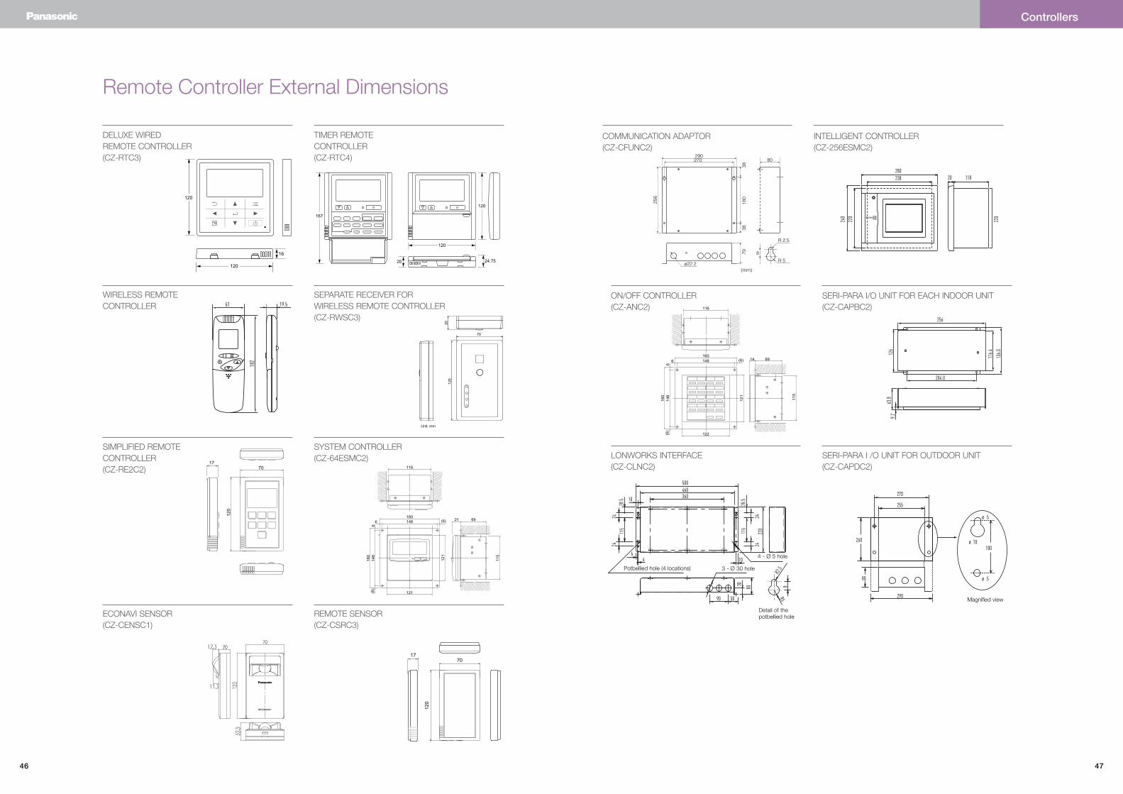
Remote Controller External Dimensions
DELUXE WIREDREMOTE CONTROLLER(CZ-RTC3)
TIMER REMOTE CONTROLLER(CZ-RTC4)
1601486 (6)
121
160
148
6(6
)
121
115
6921
116
SYSTEM CONTROLLER(CZ-64ESMC2)
WIRELESS REMOTE CONTROLLER
SEPARATE RECEIVER FORWIRELESS REMOTE CONTROLLER(CZ-RWSC3)
1770
120
66.8
116.
8
10
4.4
83.5
33.4
16.6
13
33.5
16.7
9.4
4.4
5.4
9.4
8
SIMPLIFIED REMOTE CONTROLLER(CZ-RE2C2)
1770
120
REMOTE SENSOR(CZ-CSRC3)
ECONAVI SENSOR(CZ-CENSC1)
(mm)
29080
ø22.2
256
270
180
3838
79 8
R 2.5
R 5
INTELLIGENT CONTROLLER(CZ-256ESMC2)
COMMUNICATION ADAPTOR(CZ-CFUNC2)
116
1601486 (6)
122
160
148
6(6
)
121
115
6914
ON/OFF CONTROLLER(CZ-ANC2)
SERI-PARA I/O UNIT FOR EACH INDOOR UNIT(CZ-CAPBC2)
LONWORKS INTERFACE(CZ-CLNC2)
SERI-PARA I /O UNIT FOR OUTDOOR UNIT(CZ-CAPDC2)
4 - Ø 5 hole
Magnified view
Detail of the potbellied hole
3 - Ø 30 holePotbellied hole (4 locations)
Controllers
120
120
16
70
2012
0
Unit: mm
24.7520
120
167
120