evaporators and coolers for industrial useabcflashnews.com/dotcom/manuals/im100529_en.pdf ·...
TRANSCRIPT
INSTRUCTION MANUAL IM100529 EN 2008-01
EVAPORATORS AND COOLERS FOR INDUSTRIAL USE Airmax II Model (Ammonia and Carbon Dioxide)


EN
1
Table of contents
• GENERAL
o To the user .................................................................... page 2o Safety ........................................................................... page 3o Equipment description .................................................. page 4o Table of connections ..................................................... page 5o Delivery ......................................................................... page 6
• PROVISIONS FOR MOUNTING
o Layout .......................................................................... page 7o Location ........................................................................ page 8
• MOUNTING
o Piping connections ....................................................... page 10o Defrost System ............................................................. page 11o Hot gas defrost ............................................................. page 12
• MAINTENANCE
o Replacement of motor ................................................... page 19o Replacing the electric resistors ..................................... page 19
How to contact Alfa Laval
The contact information for each country, is constantly updated on our website.
Visit www.alfalaval.com to get this information.
THE TECHNICAL INFORMATION SUPPLIED AND OTHER MINOR CHANGES CAN BE MODIFY WITHOUTNOTIFICATION.

EN
2
To the User
Dear User
This instruction manual is intended to help you deal with any problems you may encounterwhen using this equipment.
Alfa Laval recommends you to study it carefully, and to make it readily available to any personnelwho would normally install, operate and maintain the equipment.
In the unlikely event that you have a problem not covered in this manual, please do not hesitateto contact your nearest Alfa Laval representative. We will do our utmost to help you whereveryou may be located.
Alfa Laval will not be responsible for any equipment failures which occurdue to failure to consult this manual properly or to the misinterpretation ofthe instructions it contains.
Warranty conditions:
This equipment is designed to operate properly and to the rated capacity when installed inaccordance with accepted industry standards. Failure to meet the following conditions couldrender the system warranty null and void:
1. System piping must be installed in accordance with recognized industry standards andpractices.
2. Inert gas must be charged into piping during welding.
3. The system must be thoroughly leak-checked before initial charging.
4. Electrical connections must comply with the following conditions:
a. Voltages must not exceed ±5% of nameplate ratings. Frequency 50-60 Hz.b. Current absorption per phase imbalance not to exceed 2%.
5. Factory installed wiring must not be changed without Alfa Laval’s written approval.
The hazardous operations and other important information are emphasized in thissection. The warnings are highlighted by means of special signs.
Always read this manual before using the equipment!
All work on the unit must be carried out by trained staff!
ATTENTION! Indicates that special procedures must be followed to avoid seriousinjures
BE CAREFUL! Indicates that special procedures should be followed to avoid seriousdamage to the equipment.
NOTE! Indicates important information to simplify operations or to make themmore easy to understand.

EN
3
Safety
Pay ATTENTION! to the following instructions to avoid serious injury to people and /or damage to the equipment.
Lifting and Transportation
Lifting forks should be placed under appropriate areas of the wooden shipping skid.Damage may result if the forks come in direct contact with the equipment.
Before lifting the equipment1. Ensure that belts or hooks are only attached to the lifting points provided2. Ensure that equipment is stable and properly balanced before lifting.
Installation and Maintenance
Before performing any maintenance operation, the mains power supply should beswitched off, and the safety switch should be in the OFF position to avoid accidents.
No personnel should walk on or step over the equipment, since this risks personalinjury and damage to the equipment.
Before attempting maintenance of the fans, make sure they are not running and theswitch is in the OFF position. When the operation is completed, replace the safetyguards.
Fluid Hazard
As defined in Annex III of European Union Directive 67/548/EEC, Ammonia is:
Flammable Toxic by inhalation Causes burns
Avoid skin contact, liquid NH3, causes chemical burns.
As defined in Annexe IV of European Union Directive 67/548/EEC it is recommended to:
Wear protective clothing
Keep away from sources of ignition - No smoking
EN
4
General Description
Equipment description
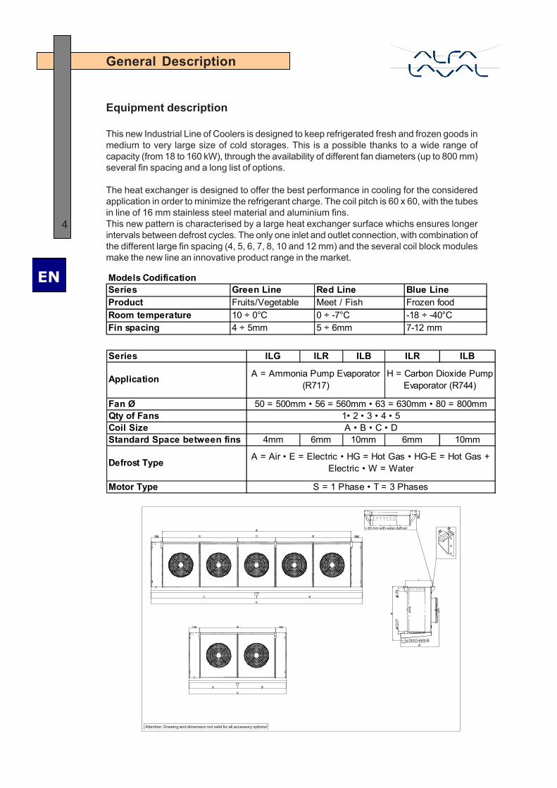
This new Industrial Line of Coolers is designed to keep refrigerated fresh and frozen goods inmedium to very large size of cold storages. This is a possible thanks to a wide range ofcapacity (from 18 to 160 kW), through the availability of different fan diameters (up to 800 mm)several fin spacing and a long list of options.
The heat exchanger is designed to offer the best performance in cooling for the consideredapplication in order to minimize the refrigerant charge. The coil pitch is 60 x 60, with the tubesin line of 16 mm stainless steel material and aluminium fins.This new pattern is characterised by a large heat exchanger surface whichs ensures longerintervals between defrost cycles. The only one inlet and outlet connection, with combination ofthe different large fin spacing (4, 5, 6, 7, 8, 10 and 12 mm) and the several coil block modulesmake the new line an innovative product range in the market.
Models CodificationSeries Green Line Red Line Blue LineProduct Fruits/Vegetable Meet / Fish Frozen foodRoom temperature 10 ÷ 0°C 0 ÷ -7°C -18 ÷ -40°CFin spacing 4 ÷ 5mm 5 ÷ 6mm 7-12 mm
Series ILG ILR ILB ILR ILB
Fan ØQty of FansCoil Size Standard Space between fins 4mm 6mm 10mm 6mm 10mm
Defrost Type
Motor Type
Application A = Ammonia Pump Evaporator (R717)
H = Carbon Dioxide Pump Evaporator (R744)
50 = 500mm • 56 = 560mm • 63 = 630mm • 80 = 800mm1• 2 • 3 • 4 • 5A • B • C • D
A = Air • E = Electric • HG = Hot Gas • HG-E = Hot Gas + Electric • W = Water
S = 1 Phase • T = 3 Phases
+ 60 mm with water defrost
INO
UT
ø DISCHARGE
Attention: Drawing and dimension not valid for all accessory options!
EN
5
General Description
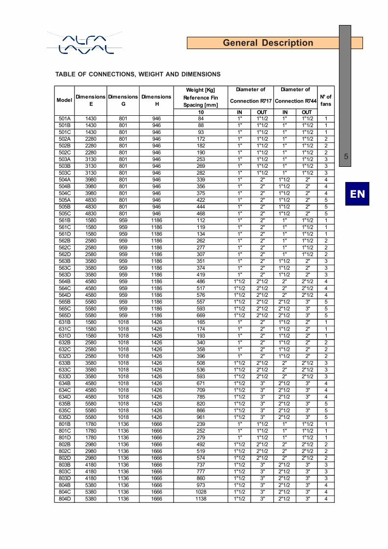
TABLE OF CONNECTIONS, WEIGHT AND DIMENSIONS
Weight [Kg]Reference Fin Spacing [mm]
10 IN OUT IN OUT501A 1430 801 946 84 1" 1"1/2 1" 1"1/2 1501B 1430 801 946 88 1" 1"1/2 1" 1"1/2 1501C 1430 801 946 93 1" 1"1/2 1" 1"1/2 1502A 2280 801 946 172 1" 1"1/2 1" 1"1/2 2502B 2280 801 946 182 1" 1"1/2 1" 1"1/2 2502C 2280 801 946 190 1" 1"1/2 1" 1"1/2 2503A 3130 801 946 253 1" 1"1/2 1" 1"1/2 3503B 3130 801 946 269 1" 1"1/2 1" 1"1/2 3503C 3130 801 946 282 1" 1"1/2 1" 1"1/2 3504A 3980 801 946 339 1" 2" 1"1/2 2" 4504B 3980 801 946 356 1" 2" 1"1/2 2" 4504C 3980 801 946 375 1" 2" 1"1/2 2" 4505A 4830 801 946 422 1" 2" 1"1/2 2" 5505B 4830 801 946 444 1" 2" 1"1/2 2" 5505C 4830 801 946 468 1" 2" 1"1/2 2" 5561B 1580 959 1186 112 1" 2" 1" 1"1/2 1561C 1580 959 1186 119 1" 2" 1" 1"1/2 1561D 1580 959 1186 134 1" 2" 1" 1"1/2 1562B 2580 959 1186 262 1" 2" 1" 1"1/2 2562C 2580 959 1186 277 1" 2" 1" 1"1/2 2562D 2580 959 1186 307 1" 2" 1" 1"1/2 2563B 3580 959 1186 351 1" 2" 1"1/2 2" 3563C 3580 959 1186 374 1" 2" 1"1/2 2" 3563D 3580 959 1186 419 1" 2" 1"1/2 2" 3564B 4580 959 1186 486 1"1/2 2"1/2 2" 2"1/2 4564C 4580 959 1186 517 1"1/2 2"1/2 2" 2"1/2 4564D 4580 959 1186 576 1"1/2 2"1/2 2" 2"1/2 4565B 5580 959 1186 557 1"1/2 2"1/2 2"1/2 3" 5565C 5580 959 1186 593 1"1/2 2"1/2 2"1/2 3" 5565D 5580 959 1186 669 1"1/2 2"1/2 2"1/2 3" 5631B 1580 1018 1426 165 1" 2" 1"1/2 2" 1631C 1580 1018 1426 174 1" 2" 1"1/2 2" 1631D 1580 1018 1426 193 1" 2" 1"1/2 2" 1632B 2580 1018 1426 340 1" 2" 1"1/2 2" 2632C 2580 1018 1426 358 1" 2" 1"1/2 2" 2632D 2580 1018 1426 396 1" 2" 1"1/2 2" 2633B 3580 1018 1426 508 1"1/2 2"1/2 2" 2"1/2 3633C 3580 1018 1426 536 1"1/2 2"1/2 2" 2"1/2 3633D 3580 1018 1426 593 1"1/2 2"1/2 2" 2"1/2 3634B 4580 1018 1426 671 1"1/2 3" 2"1/2 3" 4634C 4580 1018 1426 709 1"1/2 3" 2"1/2 3" 4634D 4580 1018 1426 785 1"1/2 3" 2"1/2 3" 4635B 5580 1018 1426 820 1"1/2 3" 2"1/2 3" 5635C 5580 1018 1426 866 1"1/2 3" 2"1/2 3" 5635D 5580 1018 1426 961 1"1/2 3" 2"1/2 3" 5801B 1780 1136 1666 239 1" 1"1/2 1" 1"1/2 1801C 1780 1136 1666 252 1" 1"1/2 1" 1"1/2 1801D 1780 1136 1666 279 1" 1"1/2 1" 1"1/2 1802B 2980 1136 1666 492 1"1/2 2"1/2 2" 2"1/2 2802C 2980 1136 1666 519 1"1/2 2"1/2 2" 2"1/2 2802D 2980 1136 1666 574 1"1/2 2"1/2 2" 2"1/2 2803B 4180 1136 1666 737 1"1/2 3" 2"1/2 3" 3803C 4180 1136 1666 777 1"1/2 3" 2"1/2 3" 3803D 4180 1136 1666 860 1"1/2 3" 2"1/2 3" 3804B 5380 1136 1666 973 1"1/2 3" 2"1/2 3" 4804C 5380 1136 1666 1028 1"1/2 3" 2"1/2 3" 4804D 5380 1136 1666 1138 1"1/2 3" 2"1/2 3" 4
Model Dimensions E
Dimensions G
Dimensions H
Diameter of Diameter ofN° of fansConnection R717 Connection R744

EN
6
General Description
DELIVERY
The equipment is delivered on pallets wrapped by nylon with following dimensions:
Please inspect all equipment upon delivery for any scuff marks or damage to the pallet’s nyloncover that could indicate damage to the equipment itself.
In case of damage during transportation, the transportation company and AL (or oneof its agents) must be informed immediately, in writing, on the delivery note (CRM).In addition, the customer should send a written report, with accompanying pictures,describing the damage in detail.
STORAGE
If the equipment has to be stored before installation (one or more months) the following precautionsare recommended:
1. Leave the equipment in its packing.2. Store it indoors, in temperature (15 to 25ºC) and humidity (50 to 70 %).3. Ensure it is not exposed to corrosive liquids or vapours.4. If the equipment is stored outdoors, it is advisable to operate the fan(s), at least once
per week, for 4 to 6 hours at a time, in order to prevent damage to the electric motors.
mm mm mm Kg
1 1540 1015 950 942 2390 1015 950 1943 3240 1015 950 2874 4090 1015 950 3825 4940 1015 950 4761 1690 1255 1120 1302 2690 1255 1120 3023 3690 1255 1120 4084 4690 1255 1120 5635 5690 1255 1120 6491 1690 1495 1120 1902 2690 1495 1120 3903 3690 1495 1120 5844 4690 1495 1120 7725 5690 1495 1120 8801 1890 1735 1190 1682 3090 1735 1190 5653 4290 1735 1190 8474 5490 1735 1190 1120
Ф 5
00Ф
560
Ф 6
30Ф
800
Fans
dia
met
er
NH3 and CO2 Models
Lenght High Width Approx. Weight
Num
ber o
f fan
s

EN
7
Provision for mounting
LAYOUT
Recommendations that have to be considered before mounting:
a) Check the structure’s load-bearing capacity against the weight of the equipment.
b) If the equipment is to be installed over the roof of a cold room, external beams orsuspension stays may be needed for better distribution of the load.
c) To avoid thermal bridges, special care should be taken with the parts crossing theisolation, preferably by using athermal stays or, at least, by ensuring high isolationto the outside environment.
d) Use anchor bolts with plane washers, locking washers and nuts, observing thedistance between the fastening axes of the equipment, as shown on the belowfigure.
A 850 1700 2550 3400 4250B / / / 1700 1700C / / / / 850L 654 654 654 654 654
A 1000 2000 3000 4000 5000B / / / 2000 2000C / / / / 1000L 724 724 724 724 724
A 1000 2000 3000 4000 5000B / / / 2000 2000C / / / / 1000L 724 724 724 724 724
A 1200 2400 3600 4800B / / 1200 1200C / / 1200 2400L 794 794 794 794
4 Fans 5 Fans
800 Ø 1 Fan 2 Fans 3 Fans 4 Fans
630 Ø 1 Fan 2 Fans 3 Fans
4 Fans 5 Fans
560 Ø 1 Fan 2 Fans 3 Fans 4 Fans 5 Fans
500 Ø 1 Fan 2 Fans 3 Fans
EN
8
Provision for mounting
LOCATION
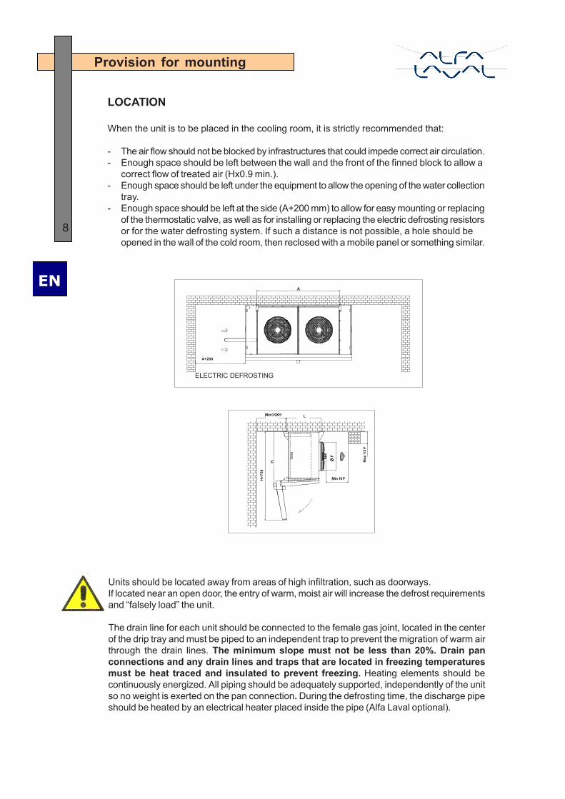
When the unit is to be placed in the cooling room, it is strictly recommended that:
- The air flow should not be blocked by infrastructures that could impede correct air circulation.- Enough space should be left between the wall and the front of the finned block to allow a
correct flow of treated air (Hx0.9 min.).- Enough space should be left under the equipment to allow the opening of the water collection
tray.- Enough space should be left at the side (A+200 mm) to allow for easy mounting or replacing
of the thermostatic valve, as well as for installing or replacing the electric defrosting resistorsor for the water defrosting system. If such a distance is not possible, a hole should beopened in the wall of the cold room, then reclosed with a mobile panel or something similar.
ELECTRIC DEFROSTING
A+200
Min 0.9XH
H+7
50
Min 10 F
Max
1/3 F
Units should be located away from areas of high infiltration, such as doorways.If located near an open door, the entry of warm, moist air will increase the defrost requirementsand “falsely load” the unit.
The drain line for each unit should be connected to the female gas joint, located in the centerof the drip tray and must be piped to an independent trap to prevent the migration of warm airthrough the drain lines. The minimum slope must not be less than 20%. Drain panconnections and any drain lines and traps that are located in freezing temperaturesmust be heat traced and insulated to prevent freezing. Heating elements should becontinuously energized. All piping should be adequately supported, independently of the unitso no weight is exerted on the pan connection. During the defrosting time, the discharge pipeshould be heated by an electrical heater placed inside the pipe (Alfa Laval optional).
L
∅∅∅∅ ∅ F
H
EN
9H
0.9xH
CORRECT! WRONG!
Provision for mounting
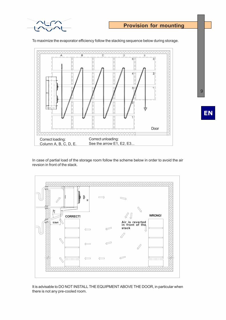
To maximize the evaporator efficiency follow the stacking sequence below during storage.
Door
Correct loading:Column A, B, C, D, E.
Correct unloading:See the arrow E1, E2, E3...
Air is revertedin front of thestack
In case of partial load of the storage room follow the scheme below in order to avoid the airrevsion in front of the stack.
It is advisable to DO NOT INSTALL THE EQUIPMENT ABOVE THE DOOR, in particular whenthere is not any pre-cooled room.

EN
10
Mounting
MOUNTING
The best solution is to fasten the equipment directly over the cold room roof. To perform thisoperation, appropriate means should be used depending on the size and weight of the equipment.It should be lifted with a forklift to facilitate installation. Appropriate tools should be used forunpacking, to avoid ruining the surfaces of the equipment. Then perform the following steps:
1. Remove the crate.2. Remove the protective film.3. Place the equipment in position on the roof and check that the fastening lugs are
correctly tied.4. Fix the equipment to the roof.5. Release the wooden base and take it down.6. Fix the drip tray.
Piping connections
Pipe sizes must be established according to good engineering design practices and inaccordance with EN 378-2. Prior to charging the system with refrigerant, the entire systemmust be pressure-tested to ensure there are no leaks, and evacuated to remove moisture.
Piping must be designed and supported independently from the evaporator to minimizethe transmission of vibrations, to permit expansion and contraction, and so as not tosubject the evaporator connections to stress. Weld all connections in accordancewith local specifications for stainless steel units.
Remove the left panel (when facing the fans); the panel has an end for hooking to the tray.Before making the connections, verify the presence of the preloaded nitrogen for the drymaintenance of the circuit.
The external piping should be well aligned.Do NOT bend the connections!
NO YES
EN
11Setting of the defrost is set by the operator in order to suit specific siterequirements and complete cleaning the unit surface from ice.
Defrost (Optional)
Defrost System
GeneralThe ambient moisture in the cold room and the water vapor coming from the dehydratationof the stored material, condenses and becomes ice when it comes in contact with the coilfins. This restricts the airflow area and, consequently, decreases the heat exchanging andthe performance of the unit. To avoid this problem, the coil must be periodically defrosted,following one of the procedures described below.
End defrost probe
This must be located on the evaporator in such a way that it is not in contact with hot air, whichcould affect its correct operation.The defrost cycle ends when the probe measures a temperature of the finned coil thatcorresponds to the set value. The defrost cycle is stopped and cooling restarts, while the fansstart again only after a suitable dripping time.
Air DefrostThis method can only be adopted if the room temperature is above 2°C.This requires the stopping of the pump and the natural heating of the evaporator by forced aircirculation through the finned coil by the fans.
Electric DefrostElectric defrost consists of a series of resistance heating elements that are inserted throughthe finned coil to theat the fins during the defrost mode. Units may also have an electric defrostpan which includes heating elements and an insulated pan cover to allow the defrost water todrain from the pan in freezing room temperatures. The system can be used for cold roomtemperatures above -35°C.The heaters are electrically connected to a common box. Connections to the power supplymust be made following the electrical drawing.
Before making the electrical connection, make sure that the system is disconnectedfrom the power supply and cannot be accidentally switched on, even by other parts.
During defrosting, the heaters are powered on, while the cooling is off.It is good practice to control the defrost using a timer and a thermostat in order to avoid anyoverheating.Do not allow long heater on times that cause coil steaming.

EN
12
Defrost (Optional)
Hot Gas DefrostThe defrosting consists of an injection of hot gas inside the evaporator piping generally usedfor the coolant fluid. During defrosting, cooling is stopped and the hot gas solenoid valve isenergized to introduce the hot gas into the unit. Below some suggestions:
PUMPOUT: min 5 to 15 minutes.The PUMPOUT step helps in the removal of liquid refrigerant from the evaporator before defrostingbegins. Less liquid means more internal evaporator surface is exposed to entering hot gas.
HOT GAS: min15 to 45 minutes.The amount of time required to remove the frost is dependent on many factors including thefollowing: design of evaporator, quantity of frost accumulation, quality and quantity of hot gassupply, size of valves, etc. Be sure that the HOT GAS step is long enough to entirely removeevery portion of the frost. Partial removal of frost is not acceptable because it will tend toincrease in mass after each defrost, eventually causing a large frost/ice problem.
EQUALIZE: 5 minutes. This step lowers the internal pressure and the likelihood of evaporator,piping and component shock when the suction stop valve is opened. Equalization also reducesthe impact of pressure changes upon the suction accumulator. Radical pressure changescause unnecessary loading and unloading of compressors and also encourage pumps tocavitate. Observing the evaporator pressure gauge during this step may help determine themost appropriate time setting.
FAN DELAY: 5 minutes.This delay enables the remaining water droplets from the melted frost to freeze to the surfaceof the evaporator, thus preventing them from blowing into the refrigerated space when air flowresumes.
BOTTOM FEED EVAPORATOR TOP FEED EVAPORATOR
EQUALIZE SOLENOID VALVE
OVERFEED SUCTION LINE
SUCTION SOLENOID VALVE,OR GAS POWERED SUCTIONSTOP VALVE, OR REGULATORWITH ELECTRIC SHUT-OFF
DEFROST RELIEF REGULATORCHECKVALVE(OPTIONAL)
LIQUID SOLENOID VALVEOVERFEED LIQUID LINE
SOFT GAS SOLENOID VALVE
HOT GAS LINE
HOT GAS SOLENOID VALVE
LIQUID SOLENOID VALVE
OVERFEED LIQUID LINE
CHECKVALVE(OPTIONAL)
DEFROST RELIEF REGULATOR WITH WIDEOPENING FEATURE FOR EQUALIZING
OVERFEED SUCTION LINE
SUCTION SOLENOID VALVE, ORGAS POWERED SUCTION STOPVALVE, OR REGULATOR WITHELECTRIC SHUT-OFF
SOFT GAS SOLENOID VALVE
HOT GAS LINE
HOT GAS SOLENOID VALVE
The scheme above is intended only as example. HG layout and piping outside of boxoutline is on customer’s charge.
Accessories and externalconnections of outlined box are notsupplied by Alfa Laval

EN
13
Defrost (Optional)
Water DefrostThe system can be used for cold rooms with temperatures from 0°C to -10°C. The necessarydefrosting water flow is shown below. Never use inlet water over 16°C to avoid mist formation.Additional components needed at low temperature (up to -30°C), contact your Alfa Lavalrepresentative about it.
Model Model Model Modell/h kPa l/h kPa l/h kPa l/h kPa
501A 1500 5 561B 3000 8 631B 3700 10 801B 5400 15501B 1900 5 561C 3600 8 631C 4500 10 801C 6500 15501C 2300 5 561D 4200 8 631D 5200 10 801D 7500 15502A 3000 7 562B 5900 10 632B 7400 15 802B 10700 20502B 3800 7 562C 7100 10 632C 8900 15 802C 12800 25502C 4500 7 562D 8300 10 632D 10400 15 802D 14900 30503A 4500 8 563B 8900 12 633B 11100 20 803B 15900 25503B 5600 8 563C 10600 12 633C 13300 20 803C 19100 30503C 6800 8 563D 12400 12 633D 15500 20 803D 22300 40504A 6000 9 564B 11800 15 634B 14800 25 804B 21200 30504B 7500 9 564C 14200 15 634C 17700 25 804C 25500 40504C 9000 9 564D 16500 15 634D 20700 25 804D 29800 50505A 7500 10 565B 14700 21 635B 18400 30505B 9400 10 565C 17700 21 635C 22100 30505C 11300 10 565D 20600 21 635D 25800 30
Water Water Water Water
Connection:Connect the water pipe to the 1” GAS joint of the defrosting box, and connect the drainagepipe in the same way to the evaporator’s collecting tray joint, located in the lower side.20° is the recommended minimum gradient for a better draining flow. Inside of the water collectiontray, an additional electric resistance should be installed, if the system is to be used forextremely low room temperatures.
The figure on the left is only a suggested piping solution. Piping connections and layout areon customer’s charge.
To inspect the defrosting box use the figure below.
EN
14
The ground connection should be made by means of a cable from the motor’s frame to theequipment structure, and from the structure to the ground of the plant.
Grounding
Electric Installation
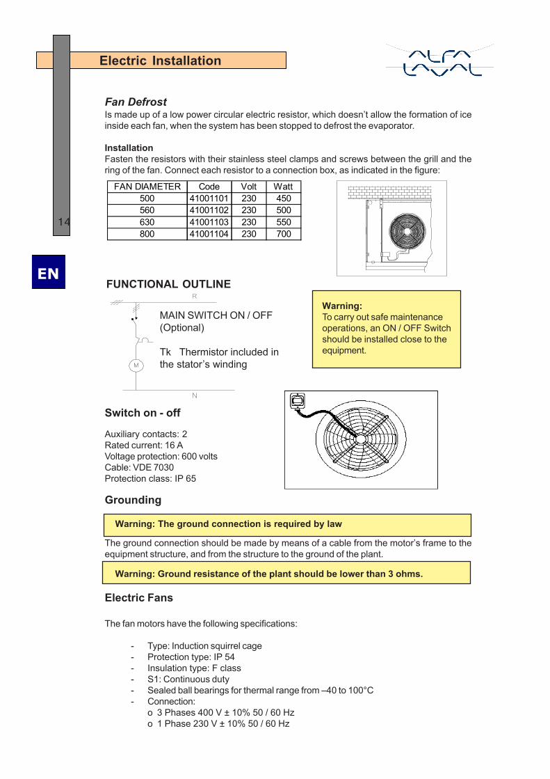
Fan DefrostIs made up of a low power circular electric resistor, which doesn’t allow the formation of iceinside each fan, when the system has been stopped to defrost the evaporator.
InstallationFasten the resistors with their stainless steel clamps and screws between the grill and thering of the fan. Connect each resistor to a connection box, as indicated in the figure:
FUNCTIONAL OUTLINE
Switch on - off
Auxiliary contacts: 2Rated current: 16 AVoltage protection: 600 voltsCable: VDE 7030Protection class: IP 65
FAN DIAMETER Code Volt Watt500 41001101 230 450560 41001102 230 500630 41001103 230 550800 41001104 230 700
MAIN SWITCH ON / OFF(Optional)
Tk Thermistor included inthe stator’s winding
Warning:To carry out safe maintenanceoperations, an ON / OFF Switchshould be installed close to theequipment.
Warning: The ground connection is required by law
Warning: Ground resistance of the plant should be lower than 3 ohms.
Electric Fans
The fan motors have the following specifications:
- Type: Induction squirrel cage- Protection type: IP 54- Insulation type: F class- S1: Continuous duty- Sealed ball bearings for thermal range from –40 to 100°C- Connection:
o 3 Phases 400 V ± 10% 50 / 60 Hzo 1 Phase 230 V ± 10% 50 / 60 Hz

EN
15
Electric Installation
Three phase motor
INTERNAL VIEWEarth screw
WIRING DIAGRAM for Connection Box for electric fan motor (JB-1)INCOMING SUPPLY 3ph - 400V - 50Hz
FAN MOTOR 1FAN MOTOR 2FAN MOTOR 3FAN MOTOR 4
CONNECTION DIAGRAM
Detail A Detail B
Detail C Detail D
Detail E
Supply Conn. Detail Speed
3ph 400v-50Hz Y Detail D Low3ph 400v-50Hz ∆ Detail E High
3ph 400v-50Hz Y Detail A High3ph 230v-50Hz Y Detail B High3ph 230v-50Hz ∆ Detail C Low
Electric Motor Connection Box
3phase double speed (standard)
3phase single speed (option)
FAN MOTORS CONNECTION
FAN MOTOR 5

EN
16
Supply Conn. Detail Speed
1ph 230v-50Hz / Detail F High
Electric Motor Connection Box
Single speed (option)
Electric Installation
Single phase motor (Option)
CONNECTION DIAGRAM
FAN MOTOR 1 FAN MOTOR 2 FAN MOTOR 3 FAN MOTOR 4
INCOMING SUPPLY 230V - 50-60Hz
MOTORCONNECTION BOX
INCOMING SUPPLY 230V - 50-60Hz
NOTE:(1) CONDENSER INCLUDED IN MOTORS
CONNECTION BOX; ITS CAPACITYDEPENDS ON THE SIZE OF THE MOTOR
CODE & COLOUR TABLE
Colour
Code EN (ENGLISH)
BK BLACK BL BLUE BR BROWN GR GREY OR ORANGE RD RED WH WHITE Y/G YELLOW/GREEN
Detail F
FAN MOTOR 5
ELECTRIC FAN MOTORCONNECTION
EN
17
Electric Installation
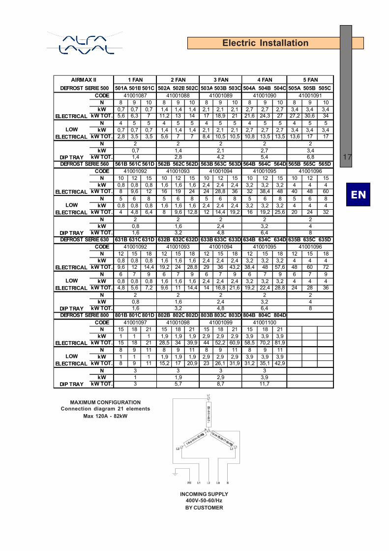
501A 501B501C 502A 502B502C 503A 503B 503C 504A 504B 504C 505A 505B 505CCODE
N 8 9 10 8 9 10 8 9 10 8 9 10 8 9 10kW 0,7 0,7 0,7 1,4 1,4 1,4 2,1 2,1 2,1 2,7 2,7 2,7 3,4 3,4 3,4
kW TOT. 5,6 6,3 7 11,2 13 14 17 18,9 21 21,6 24,3 27 27,2 30,6 34N 4 5 5 4 5 5 4 5 5 4 5 5 4 5 5
kW 0,7 0,7 0,7 1,4 1,4 1,4 2,1 2,1 2,1 2,7 2,7 2,7 3,4 3,4 3,4kW TOT. 2,8 3,5 3,5 5,6 7 7 8,4 10,5 10,5 10,8 13,5 13,5 13,6 17 17
NkW
kW TOT.561B 561C561D 562B 562C562D 563B 563C 563D 564B 564C 564D 565B 565C 565D
CODEN 10 12 15 10 12 15 10 12 15 10 12 15 10 12 15
kW 0,8 0,8 0,8 1,6 1,6 1,6 2,4 2,4 2,4 3,2 3,2 3,2 4 4 4kW TOT. 8 9,6 12 16 19 24 24 28,8 36 32 38,4 48 40 48 60
N 5 6 8 5 6 8 5 6 8 5 6 8 5 6 8kW 0,8 0,8 0,8 1,6 1,6 1,6 2,4 2,4 2,4 3,2 3,2 3,2 4 4 4
kW TOT. 4 4,8 6,4 8 9,6 12,8 12 14,4 19,2 16 19,2 25,6 20 24 32N
kWkW TOT.
631B 631C631D 632B 632C632D 633B 633C 633D 634B 634C 634D 635B 635C 635DCODE
N 12 15 18 12 15 18 12 15 18 12 15 18 12 15 18kW 0,8 0,8 0,8 1,6 1,6 1,6 2,4 2,4 2,4 3,2 3,2 3,2 4 4 4
kW TOT. 9,6 12 14,4 19,2 24 28,8 29 36 43,2 38,4 48 57,6 48 60 72N 6 7 9 6 7 9 6 7 9 6 7 9 6 7 9
kW 0,8 0,8 0,8 1,6 1,6 1,6 2,4 2,4 2,4 3,2 3,2 3,2 4 4 4kW TOT. 4,8 5,6 7,2 9,6 11 14,4 14 16,8 21,6 19,2 22,4 28,8 24 28 36
NkW
kW TOT.801B 801C801D 802B 802C802D 803B 803C 803D 804B 804C 804D
CODEN 15 18 21 15 18 21 15 18 21 15 18 21
kW 1 1 1 1,9 1,9 1,9 2,9 2,9 2,9 3,9 3,9 3,9kW TOT. 15 18 21 28,5 34 39,9 44 52,2 60,9 58,5 70,2 81,9
N 8 9 11 8 9 11 8 9 11 8 9 11kW 1 1 1 1,9 1,9 1,9 2,9 2,9 2,9 3,9 3,9 3,9
kW TOT. 8 9 11 15,2 17 20,9 23 26,1 31,9 31,2 35,1 42,9N
kWkW TOT.
2 FAN 3 FAN 4 FAN 5 FAN DEFROST SERIE 500
ELECTRICAL
41001087 41001088 41001089 41001090 41001091
AIRMAX II 1 FAN
LOW ELECTRICAL
DIP TRAY
2 2
1,4 2,8 DEFROST SERIE 560
2 2 20,7 1,4 2,1 2,7 3,4
41001094
4,2 5,4 6,8
0,8
ELECTRICAL
41001092 41001093
4
41001095 41001096
LOW ELECTRICAL
DIP TRAY
2 2 2 2 2
4,8 6,41,6 2,4 3,2
8 DEFROST SERIE 630
ELECTRICAL
41001092 41001093 41001094 41001095 41001096
1,6 3,2
LOW ELECTRICAL
DIP TRAY
2 2
1,6 3,2
2 2 20,8 1,6 2,4 3,2 4
4,8 6,4 8 DEFROST SERIE 800
ELECTRICAL
41001097 41001098 41001099 41001100
LOW ELECTRICAL
DIP TRAY
3 3 3 31 1,9 2,9 3,93 5,7 8,7 11,7
INCOMING SUPPLY400V-50-60/HzBY CUSTOMER
MAXIMUM CONFIGURATIONConnection diagram 21 elements
Max 120A - 82kW

EN
18
Maintenance
Routine MaintenanceTo guarantee the thermal efficiency of the equipment, the units should be inspected periodically.Visually inspect the units and listen for any signs of mechanical wear.Note that the motors are totally enclosed, with sealed bearings that do not require regreasing.Inspect the unit for debris or deposits, particularly on the air inlet face of the fins and the drainpan area, and clean using water with a suitably mild cleaning agent, as required (ex. AlpaconDegreaser). Check the frequency and duration of frost events and inspect the unit for icebuildup at least monthly.
CleaningNote that the equipment could be damaged by incompatible water condensate from defrosting,contaminated by airborne impurities. It is the responsibility of the owner operator to befamiliar with these chemicals and the room environment and to select compatibleagents and construction materials. A lowpressure water jet or non aggressive liquids canbe used as well.
Warning: Before attempting to carry out maintenance, the power supply should be turned offfrom the sectional board. As a further safety measure, the operator can also turn the ON / OFFswitch to the OFF position to avoid accidents.
Periodic preventive controlsEvery three months the following controls should be performed:− Check the equipment fastening.− Ensure that the electric connection terminal studs are properly tightened, to avoid losses
and wear due to sparks.− Ensure that the wiring is in good condition (it should not have cuttings or deterioration signs).− Check the ground connection resistance (< to 3 ohms).− Check that the current load indicated on a current clamp tester is equal or slightly lower
than the rated, when the fan(s) are running at rated rpm.
If the equipment remain inoperative for prolonged periods (three or more months), itis advisable to operate the fan(s), at least once a month, for 3 to 4 hours each time.
Tools and accessories for maintenance− Open end or combination wrenches kit (millimeters), (sizes from 10 to 20 mm)− Open end or combination wrenches kit (inches), (sizes from ½” to 2”)
Troubleshooting
PROBLEM POSSIBLE CAUSE SOLUTION Too short defrosting stage Increase the defrosting time Too much time between defrosting cycles
Increase the defrosting cycles. Check the absence of flattened tubes
Insufficient leaking time. Control the goods and, if necessary, make sure that has been treated in the freezing tunnel to extract the humidity.
Air infiltrates too many times through door openings.
Reduce the opening frequency and, if present, eliminate the fissures.
Frosted evaporator.
Burnt electric resistors Replace the worn out resistors. Damaged fan motor Replace. Line voltage lower than the tolerance limits.
Check the voltage value between phases with a voltmeter.
Lack of a phase Check the voltage value between phases, check the power supply line
Blocked fans
Overloaded motor Check with an Ammeter
Damaged evaporator Deformed fins. Straighten the fins with an appropriated comb.

EN
19
Maintenance
Replacement of motorControl electric fans periodically to ensure that they are working properly.In the event of electric or mechanical failures, the motor should be replaced as follows:
1. Make sure that the power supply has been switched off, by placing the safety switchin the OFF position.
2. Then, open the electric motor derivation box, disconnect and remove the electricwires.
3. Place the new fan motor and install it.4. Make the electric connection.
Panel
Fan motor
Replacing the electric resistorsIf part of the finned block has not been defrosted, disconnect the resistor positioned in theunheated area, and check whether it has burned out or broken using an ohmmeter. If necessary,replace the resistor as follows:
Finned block- Disassemble the side panels.- Open the derivation box.- Disconnect the defective resistors’ wires from the terminal block.- Remove the screw that secures the clamp to the coil.- Remove the connection cable that links the two elements.- Remove the bar resistors from the opposite side where the derivation box is placed.- Install the new resistor using small tubes where the connection wires will be threaded
through, to facilitate the displacement inside the finned block.- Fasten the resistor to the coil with the clamp placed over the resistor, and fix it with the screw.- Connect the wires to the terminal block in the original position.- Close the derivation box.- Assemble the side panels.
Tray- Open the right side panel and the outside collecting tray.- Disconnect the defective resistor’ wires from the terminal block.- Remove the screw that secures the stainless steel clamp blocking the counter tray.- Replace the resistor and fasten the clamp as explained above.- Connect the wires to the terminal block in the original position.- Close the tray and the side panel.
Checking the electric contacts- Check the tightness of all the electric connections in the terminal block.- Ensure that the electric wires are in good condition (the insulating sheath should not
have cuts and should be fastened over the fixed parts).- Check the grounding connection and its efficiency using appropriate instruments.
EN
20
Maintenance
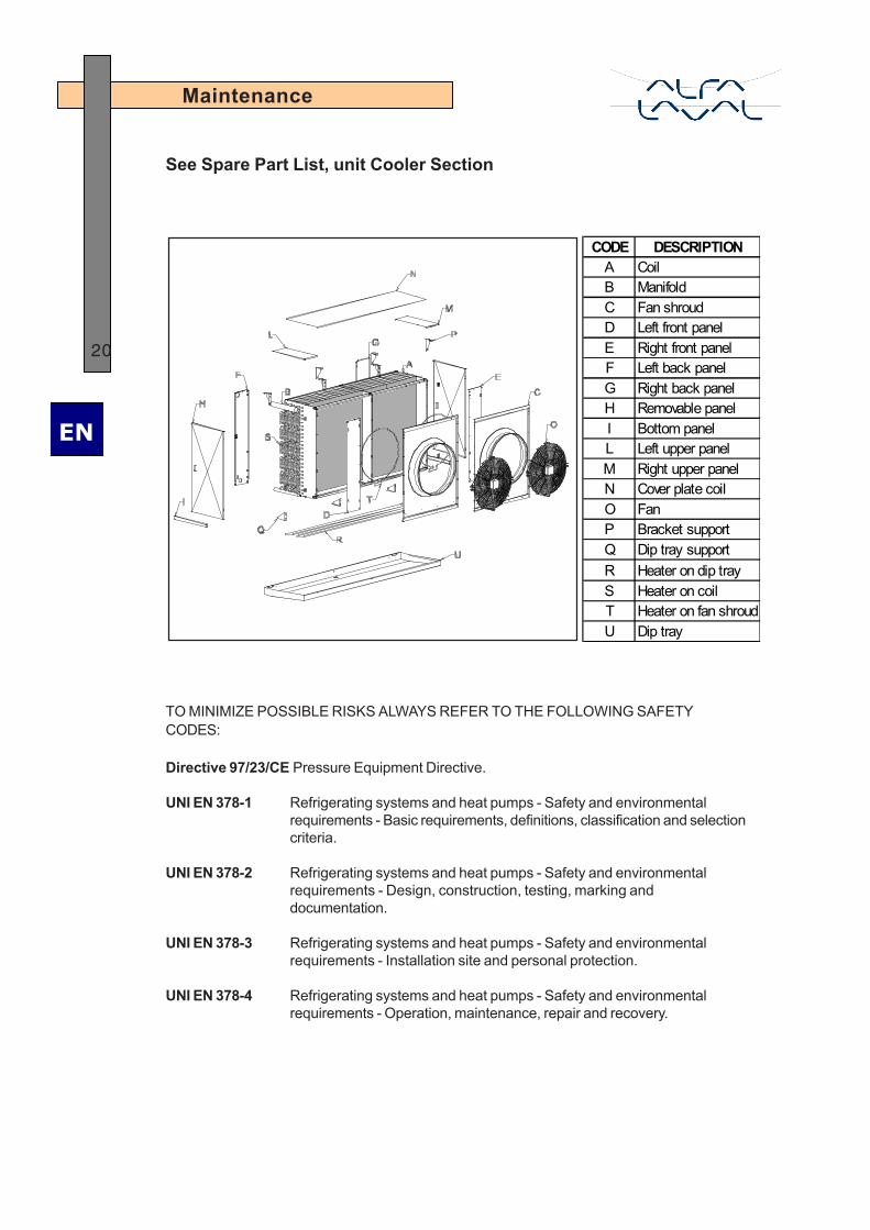
See Spare Part List, unit Cooler Section
CODE DESCRIPTIONA CoilB ManifoldC Fan shroudD Left front panelE Right front panelF Left back panelG Right back panelH Removable panelI Bottom panelL Left upper panelM Right upper panelN Cover plate coilO FanP Bracket supportQ Dip tray supportR Heater on dip trayS Heater on coilT Heater on fan shroudU Dip tray
TO MINIMIZE POSSIBLE RISKS ALWAYS REFER TO THE FOLLOWING SAFETYCODES:
Directive 97/23/CE Pressure Equipment Directive.
UNI EN 378-1 Refrigerating systems and heat pumps - Safety and environmentalrequirements - Basic requirements, definitions, classification and selectioncriteria.
UNI EN 378-2 Refrigerating systems and heat pumps - Safety and environmentalrequirements - Design, construction, testing, marking anddocumentation.
UNI EN 378-3 Refrigerating systems and heat pumps - Safety and environmentalrequirements - Installation site and personal protection.
UNI EN 378-4 Refrigerating systems and heat pumps - Safety and environmentalrequirements - Operation, maintenance, repair and recovery.

Errata
Manual AirMax II
The Water defrost paragraph on page 9 s to be replaced by the following text.
Water defrost
The system can be used for cold rooms with room temperatures above 4 °C. When the temperature drops below 4°C the risk of freezing affects the defrost effect and could damage the unit. According to tests made in the lab and tests on installations we have defined the water defrost guidelines for an homogeneous shower and a reduced sputtering effect:
• 0.5 m3/h water per module
• no pressure on water inlet or as low as possible
• laminar flow into connecting piping
• water basin flooded
• never use inlet water above 16°C to avoid mist formation