alfablue dry coolers - cinto.ru · alfablue dry coolers general content. ... alfa laval dry coolers...
TRANSCRIPT

AlfaBlue Dry Coolers GGeneral Content
.
kyAlfaBlue Dry Coolersky General Content
General FeaturesA dry cooler is a forced convection air-cooled fluid cooler, designedfor outdoor installation. Air is forced over a finned coil which containsthe working fluid such as water or a water and glycol mix. All productsare designed to satisfy both commercial and industrial refrigeration, airconditioning, and retail refrigeration. Dry coolers are available in thefollowing versions:• Vertical installation (V)• Horizontal installation (H)
Relative footprint, low consumption and low noise levels are the keysto this series’ success.
Certifications and reliabilityAll Dry coolers are guaranteed by Eurovent "Certify All". Alfa Lavalquality systems fully comply with ISO 9001, and all of our products aremanufactured in strict accordance with CE regulations.
CapacityThe standard conditions stated in the catalogue are in accordancewith EN 1048 (water, T.air= 25°C, Tin= 40°C, Tout= 35°C). All modelshave many circuiting options which can be selected to optimise dutywith required fluid pressure drops and flow rates. Due to the multiplecombinations of temperatures, flow rates and working fluids that canbe encountered, it is not possible to display all the capacities in thecatalogue.How to determine the dry cooler’s capacity:
Capacity required (e.g. 34%) = Nominal Capacity. (water) x 1.07 x F1 x F2
Altitude (m) 0 500 1000 1500 2000F1 1 1,028 1,06 1,09 1,12
Fin material Al Al Prv CuF2 1 1,03 0,97
Against FreezingGiven that the tubes are permanently in a horizontal position, it cannotbe guaranteed that they drain completely when stoppages occur. As aresult of this, a dry cooler containing water must be protected againstfreezing with an adequate amount of glycol.
Tube Protection
Due to the thermal expansion of the copperpipes, all metal sheets are equipped with an alu-minium plate with collars. This plate supportsthe tube and therefore the pipes must not comeinto contact with the metal sheets. With thissolution, the vibrations and thermal expansionare absorbed by the aluminium sheet. Leakscaused by friction cannot occur. The rigidity ofthe coil is sustained effectively.
Energy Efficiency Class
Energy efficiency class of air cooledcondensers
Class Energy consumption RA Extremely low R>110B Very low 70 R<110C Low 45 R<70D Medium 30 R<45E High R<30
R = Condenser capacity ( T15K) / motorpower consumption.
Test and cleaningCoils are cleaned thoroughly in order to remove any traces of oil.Each heat exchanger undergoes a pressure and leak test with dry airat 10bar (PS= 9bar).
241
AlfaBlue Dry Coolers GGeneral Content
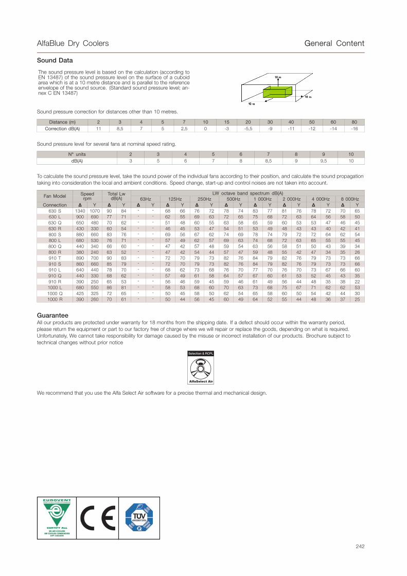
Sound Data
The sound pressure level is based on the calculation (according toEN 13487) of the sound pressure level on the surface of a cuboidarea which is at a 10 metre distance and is parallel to the referenceenvelope of the sound source. (Standard sound pressure level; an-nex C EN 13487)
Sound pressure correction for distances other than 10 metres.
Distance (m) 2 3 4 5 7 10 15 20 30 40 50 60 80Correction dB(A) 11 8,5 7 5 2,5 0 -3 -5,5 -9 -11 -12 -14 -16
Sound pressure level for several fans at nominal speed rating.
N° units 2 3 4 5 6 7 8 9 10dB(A) 3 5 6 7 8 8,5 9 9,5 10
To calculate the sound pressure level, take the sound power of the individual fans according to their position, and calculate the sound propagationtaking into consideration the local and ambient conditions. Speed change, start-up and control noises are not taken into account.
LW octave band spectrum dB(A)Fan Model Speed
rpmTotal Lw
dB(A) 63Hz 125Hz 250Hz 500Hz 1 000Hz 2 000Hz 4 000Hz 8 000HzConnection Y Y Y Y Y Y Y Y Y Y
630 S 1340 1070 90 84 - - 68 66 76 72 78 74 83 77 81 76 78 72 70 65630 L 900 690 77 71 - - 62 55 69 63 72 65 75 68 72 63 64 56 58 50630 Q 650 480 70 62 - - 51 48 60 55 63 58 65 59 60 53 53 47 46 45630 R 430 330 60 54 - - 46 45 53 47 54 51 53 49 48 43 43 40 42 41800 S 880 660 83 76 - - 69 56 67 62 74 69 78 74 79 72 72 64 62 54800 L 680 530 76 71 - - 57 49 62 57 69 63 74 68 72 63 65 55 55 45800 Q 440 340 66 60 - - 47 42 57 48 59 54 63 56 58 51 50 43 39 34800 R 380 240 63 52 - - 47 42 54 44 57 47 59 48 55 42 47 34 35 26910 T 890 700 90 83 - - 72 70 79 73 82 76 84 79 82 76 79 73 73 66910 S 860 660 85 79 - - 72 70 79 73 82 76 84 79 82 76 79 73 73 66910 L 640 440 78 70 - - 68 62 73 68 76 70 77 70 76 70 73 67 66 60910 Q 440 330 68 62 - - 57 49 61 58 64 57 67 60 61 53 52 45 43 35910 R 390 250 65 53 - - 56 46 59 45 59 46 61 49 56 44 48 35 38 221000 L 680 550 86 81 - - 58 53 68 60 70 63 73 68 75 67 71 62 62 531000 Q 425 325 72 65 - - 50 45 58 50 62 54 65 58 60 50 54 42 44 301000 R 390 260 70 61 - - 50 44 56 45 60 49 64 52 55 44 48 36 37 25
GuaranteeAll our products are protected under warranty for 18 months from the shipping date. If a defect should occur within the warranty period,please return the equipment or part to our factory free of charge where we will repair or replace the goods, depending on what is required.Unfortunately, We cannot take responsibility for damage caused by the misuse or incorrect installation of our products. Brochure subject totechnical changes without prior notice
AlfaSelect Air
We recommend that you use the Alfa Select Air software for a precise thermal and mechanical design.
242

BDM - Single Fan Row PProduct description
.
kyBDM - Single Fan Rowky Product description
.
ApplicationAlfa Laval Dry Coolers can be used in refrigeration, air conditioningequipment and in industrial cooling (cooling of water or other differentfluids, food, power, process and general industry).
Standard designCoilThis innovative heat exchanger gives excellent heat transfer withminimal refrigerant charge, as a result of new fin corrugation andsmooth tubing developed by Alfa Laval. In the standard execution, theheat exchanger is manufactured from copper tubes and aluminumfins with spacing 2.1 mm. BDM is a Single coil model; each manifoldprovided with draining and venting nozzles. Each heat exchangerundergoes a pressure and leak test with dry air at 10bar (designpressure is 9bar).
CasingCasework made with pre-painted galvanized steel sheets. A newframe design provides high rigidity for heavy applications. Thenew system protects the heat exchanger tubes completely duringtransportation and against vibration and thermal expansion while inoperation. Supports manufactured in galvanized steel, with optimizedlength to permit uniform air suction in the coil.
Benefits• Footprint: Optimised footprint with higher capacity.• 630, 800, 910, 1000 mm fan
• More performance available• Low power consumption fan motor• More noise level options• Flexible design
• All parts are painted in accordance with RAL 9002• No cut edges• Higher corrosion resistance, double surface treatment• External Corrosion Class C4
• Coil design: Increased heat transfer thanks to innovative fincorrugation
• Casing: Strong casing with new design• High Energy Efficiency: best performance with low energy
consumption
Options• Non-standard fin spacing: for heavy dusty environment• Coil treatment: corrosion resistance, ideal for aggressive
environments• Vibration Dampers: for reducing vibrations• Electrical parts
• Switch on/off: Local safety switch is wired to isolate the fan, andis also available for EMC switches.
• Terminal Box: all fans wired for an easy electrical connection• Switchboard
• Cabling: ready to install• Frequency Converter design: units can run under frequency control
(when air temperature is below the design, it allows energy saving,noise reduction and longer fan motor life)
• Fan step control:• Energy saving• Cheapest method of controlling performance
• Fan speed control• Energy saving• Noise reduction when the air temperature is below the design
temperature.• Variable and efficient speed control according to the heat
rejected• Better performance control
• Special fans• 480/3ph-60Hz IP54: High adaptability for every market• IP 55: High protection fan for use in tropical or desert areas• High temperature Electric Motors: Suitable for high temperature
fluids when the outlet air is too hot for the standard fan motors.
243
BDM - Single Fan Row PProduct description
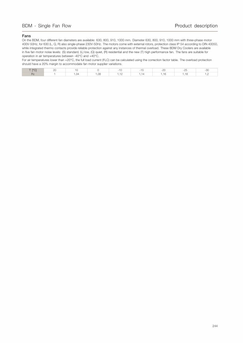
FansOn the BDM, four different fan diameters are available: 630, 800, 910, 1000 mm. Diameter 630, 800, 910, 1000 mm with three-phase motor400V-50Hz, for 630 (L, Q, R) also single-phase 230V-50Hz. The motors come with external rotors, protection class IP 54 according to DIN 40050,while integrated thermo contacts provide reliable protection against any instances of thermal overload. These BDM Dry Coolers are availablein five fan motor noise levels: (S) standard, (L) low, (Q) quiet, (R) residential and the new (T) high performance fan. The fans are suitable foroperation in air temperatures between -40°C and +40°C.For air temperatures lower than +20°C, the full load current (FLC) can be calculated using the correction factor table. The overload protectionshould have a 20% margin to accommodate fan motor supplier variations.
T [°C] 20 10 0 -10 -15 -20 -25 -30Fc 1 1,04 1,08 1,12 1,14 1,16 1,18 1,2
244

BDM - Single Fan Row TTechnical Data
.
Capacity [kW] Pressure Dropfluid [kPa] Airflow [m3/h] Lp
[dB(A)]* Motor (3/400V-50Hz) Fans SurfaceTubevol-ume
E.E.C.** Conn. SizeModel
Y 230V50Hz Y Y Y Y
Motor(230V-50Hz) N° x D
[mm]m2 dm3 Y Inlet Outlet
Ø 630
BDMS631A 36,0 31,3 - 20,8 16,3 17747 13697 56 50 1X630 88,2 8 E E 1"1/2 1"1/2
BDMS631B 48,1 40,7 - 70,0 52,5 17182 13120 56 50 1X630 132,3 11 E E 1"1/2 1"1/2
BDMS631C 55,0 45,4 - 53,7 38,3 16576 12555 56 50 1X630 176,5 15 E D 2" 2"
BDMS631D 59,3 47,9 - 40,8 28,2 15971 12024 56 50 1X630 220,6 19 E D 2" 2"
BDMS632A 73,9 64,3 - 79,0 61,8 35414 27307 59 53 2X630 172,6 15 E E 1"1/2 1"1/2
BDMS632B 94,8 80,3 - 59,9 45,0 34227 26108 59 53 2X630 258,9 22 E E 1"1/2 1"1/2
BDMS632C 109,7 90,5 - 77,6 55,3 32966 24943 59 53 2X630 345,2 30 E D 2" 2"
BDMS632D 118,1 95,4 - 59,3 40,7 31714 23853 59 53 2X630 431,5 37 E D 2" 2"
BDMS633A 109,4 95,3 - 54,9 43,0 53078 40914 61 55 3X630 256,9 22 E E 1"1/2 1"1/2
BDMS633B 140,5 119,0 - 41,7 31,1 51269 39094 61 55 3X630 385,4 33 E E 2" 2"
BDMS633C 163,8 135,1 - 73,3 52,3 49351 37329 61 55 3X630 513,9 44 E D 2" 2"
BDMS633D 176,4 142,5 - 58,3 40,0 47454 35680 61 55 3X630 642,4 55 E D 2" 2"
BDMS634A 144,2 125,6 - 37,8 29,6 70742 54521 62 56 4X630 341,3 29 E E 2" 2"
BDMS634B 185,3 156,9 - 28,7 21,4 68310 52079 62 56 4X630 512 44 E E 2" 1/2 2" 1/2
BDMS634C 212,5 175,5 - 22,1 15,7 65736 49713 62 56 4X630 682,6 59 E D 2" 1/2 2" 1/2
BDMS634D 234,4 189,5 - 54,1 37,4 63192 47505 62 56
P=2600WIn=4.8An=1310min-1
P=1600WIn=2.7An=100min-1
-
4X630 853,3 74 E D 2" 1/2 2" 1/2
BDML631A 26,8 23,99 26,8 51,19 42,04 9778 8175 45 40 1X630 88,2 8 D C 1"1/2 1"1/2
BDML631B 32,8 28,61 32,7 35,72 28,13 9504 7855 45 40 1X630 132,3 11 C C 1"1/2 1"1/2
BDML631C 36,1 30,87 35,9 25,44 19,25 9232 7552 45 40 1X630 176,5 15 C B 2" 2"
BDML631D 37,9 31,78 37,6 18,65 13,67 8968 7268 45 40 1X630 220,6 19 C B 2" 2"
BDML632A 53,5 47,86 53,5 74,16 60,88 19515 16299 48 43 2X630 172,6 15 D C 1"1/2 1"1/2
BDML632B 65,4 57,08 65,2 51,77 40,71 18945 15638 48 43 2X630 258,9 22 C C 1"1/2 1"1/2
BDML632C 72,9 62,16 72,5 83,55 63,04 18383 15014 48 43 2X630 345,2 30 C B 2" 2"
BDML632D 76,4 63,91 75,8 68,53 50,04 17837 14433 48 43 2X630 431,5 37 C B 2" 2"
BDML633A 79,9 71,49 79,9 70,15 57,59 29251 24423 50 45 3X630 256,9 22 D C 1"1/2 1"1/2
BDML633B 98,7 86,13 98,4 92,63 73,3 28385 23421 50 45 3X630 385,4 33 C C 2" 2"
BDML633C 108,8 92,71 108,1 65,92 49,73 27531 22475 50 45 3X630 513,9 44 C B 2" 2"
BDML633D 114,5 95,7 113,6 80,71 58,88 26705 21596 50 45 3X630 642,4 55 C B 2" 2"
BDML634A 106,4 95,11 106,2 68,16 55,96 38987 32547 51 46 4X630 341,3 29 D C 2" 2"
BDML634B 130,1 113,49 129,6 47,64 37,49 37825 31203 51 46 4X630 512 44 C C 2" 1/2 2" 1/2
BDML634C 145,1 123,64 144,2 76,98 58,06 36680 29935 51 46 4X630 682,6 59 C B 2" 1/2 2" 1/2
BDML634D 151,9 127,04 150,8 58,46 42,66 35573 28759 51 46
P=690WIn=1.25An=900min-1
P=480WIn=0.78An=690min-1
P=780WIn=3.5An=900min-1
4X630 853,3 74 C B 2" 1/2 2" 1/2
BDMQ631A 21,9 19,01 21,9 36,04 28 7098 5761 38 31 1X630 88,2 8 B A 1"1/2 1"1/2
BDMQ631B 25,9 21,8 25,9 23,38 17,33 6868 5497 38 31 1X630 132,3 11 B A 1"1/2 1"1/2
BDMQ631C 27,8 22,84 27,8 16,02 11,33 6643 5253 38 31 1X630 176,5 15 B A 2" 2"
BDMQ632A 43,7 37,94 43,7 52,23 40,56 14161 11480 41 34 2X630 172,6 15 B A 1"1/2 1"1/2
BDMQ632B 51,7 43,49 51,7 33,89 25,1 13683 10935 41 34 2X630 258,9 22 B A 1"1/2 1"1/2
BDMQ632C 56,0 45,91 56,0 52,51 36,97 13220 10434 41 34 2X630 345,2 30 B A 2" 2"
BDMQ633A 65,3 56,69 65,4 49,45 38,39 21223 17198 43 36 3X630 256,9 22 B A 1"1/2 1"1/2
BDMQ633B 77,9 65,54 77,9 60,54 44,84 20497 16372 43 36 3X630 385,4 33 B A 2" 2"
BDMQ633C 84,1 68,83 84,1 69,41 48,82 19796 15615 43 36 3X630 513,9 44 B A 2" 2"
BDMQ634A 87,0 75,43 87,0 48,06 37,32 28285 22916 44 37 4X630 341,3 29 B A 2" 2"
BDMQ634B 104,0 87,48 104,0 75,34 55,79 27312 21810 44 37 4X630 512 44 B A 2" 1/2 2" 1/2
BDMQ634C 112,2 91,83 112,2 90,86 63,87 26371 20795 44 37
P=330WIn=0.80An=650min-1
P=190WIn=0.38An=480min-1
P=400WIn=1.8An=650min-1
4X630 682,6 59 B A 2" 1/2 2" 1/2
BDMR631A 16,4 13,85 - 21,42 15,86 4662 3735 28 22 1X630 88,2 8 A A 1"1/2 1"1/2
BDMR631B 18,6 15,26 - 13,05 9,24 4501 3560 28 22 1X630 132,3 11 A A 1"1/2 1"1/2
BDMR632A 32,7 27,68 - 31,1 23,15 9300 7442 31 25 2X630 172,6 15 A A 1"1/2 1"1/2
BDMR632B 37,7 30,88 - 80,37 56,7 8964 7080 31 25 2X630 258,9 22 A A 1"1/2 1"1/2
BDMR633A 49,3 41,74 - 55,65 41,34 13937 11149 33 27 3X630 256,9 22 A A 1"1/2 1"1/2
BDMR633B 56,2 46,07 - 56,65 39,97 13427 10600 33 27 3X630 385,4 33 A A 2" 2"
BDMR634A 65,8 55,68 - 65,01 48,27 18574 14856 34 28 4X630 341,3 29 A A 2" 2"
BDMR634B 75,0 61,48 - 74,17 52,3 17889 14120 34 28
P=125WIn=0.33An=430min-1
P=85WIn=0.14An=330min-1
-
4X630 512 44 A A 2" 1/2 2" 1/2
Nominal capacities according to standard EN1048 (water Tair=25°C, Tin=40°C,Tout=35°C).*See the General Contents for more details.**Energy Efficiency Class: see "General Contents" for more details.
245

BDM - Single Fan Row TTechnical Data
Capacity [kW] Pressure Dropfluid [kPa] Airflow [m3/h] Lp
[dB(A)]* Motor (3/400V-50Hz) Fans SurfaceTubevol-ume
E.E.C.** Conn. SizeModel
Y 230V50Hz Y Y Y Y
Motor(230V-50Hz) N° x D
[mm]m2 dm3 Y Inlet Outlet
Ø 630 LONG
BDMS631AL 41,5 36,0 - 32,6 25,4 18073 14071 56 50 1x630 88,2 8 E E 1"1/2 1"1/2
BDMS631BL 52,8 44,7 - 24,3 18,2 17748 13698 56 50 1x630 132,3 11 E D 1"1/2 1"1/2
BDMS631CL 61,4 50,6 - 42,5 30,0 17379 13314 56 50 1x630 176,5 15 E D 2" 2"
BDMS631DL 66,2 53,5 - 36,7 25,2 16984 12931 56 50 1x630 220,6 19 E D 2" 2"
BDMS632AL 83,9 72,7 - 66,3 51,6 36111 28098 59 53 2x630 172,6 15 E E 1"1/2 1"1/2
BDMS632BL 106,8 90,2 - 52,8 39,4 35434 27328 59 53 2x630 258,9 22 E D 1"1/2 1"1/2
BDMS632CL 123,0 101,3 - 71,3 50,2 34666 26536 59 53 2x630 345,2 30 E D 2" 2"
BDMS632DL 132,4 106,9 - 54,6 37,5 33848 25749 59 53 2x630 431,5 37 E D 2" 2"
BDMS633AL 126,2 109,5 - 89,1 69,3 54148 42125 61 55 3x630 256,9 22 E E 2" 2"
BDMS633BL 160,7 135,6 - 67,0 49,5 53118 40957 61 55 3x630 385,4 33 E D 2" 2"
BDMS633CL 183,0 150,8 - 50,5 35,6 51951 39757 61 55 3x630 513,9 44 E D 2" 2"
BDMS633DL 197,1 159,3 - 38,7 26,6 50709 38565 61 55
P=2600WIn=4.8An=1310min-1
P=1600WIn=2.7An=1000min-1
-
3x630 642,4 55 E D 2"1/2 2"1/2
BDML631AL 29,1 26,1 29,2 17,4 14,4 9959 8393 45 40 1x630 88,2 8 C C 1"1/2 1"1/2
BDML631BL 36,2 31,6 36,2 51,6 40,8 9779 8175 45 40 1x630 132,3 11 C B 1"1/2 1"1/2
BDML631CL 39,6 34,0 39,5 36,4 27,8 9596 7961 45 40 1x630 176,5 15 C B 2" 2"
BDML631DL 41,4 35,0 41,2 26,6 19,7 9414 7753 45 40 1x630 220,6 19 C B 2" 2"
BDML632AL 59,6 53,3 59,7 68,0 55,6 19897 16760 48 43 2x630 172,6 15 C C 1"1/2 1"1/2
BDML632BL 71,9 62,8 71,8 46,2 36,2 19525 16312 48 43 2x630 258,9 22 C B 1"1/2 1"1/2
BDML632CL 79,2 67,9 78,9 54,3 41,4 19149 15871 48 43 2x630 345,2 30 C B 2" 2"
BDML632DL 82,7 69,8 82,3 39,6 29,4 18773 15445 48 43 2x630 431,5 37 C B 2" 2"
BDML633AL 88,6 79,2 88,7 47,7 39,4 29835 25127 50 45 3x630 256,9 22 C C 2" 2"
BDML633BL 108,4 94,7 108,2 78,4 62,0 29271 24448 50 45 3x630 385,4 33 C B 2" 2"
BDML633CL 118,5 101,6 118,1 52,0 39,7 28701 23781 50 45 3x630 513,9 44 C B 2" 2"
BDML633DL 124,5 105,0 123,9 71,2 52,8 28132 23136 50 45
P=690WIn=1.25An=900min-1
P=480WIn=0.78An=690min-1
P=780WIn=3.5An=900min-1
3x630 642,4 55 C B 2"1/2 2"1/2
BDMQ631AL 24,3 21,1 24,3 52,5 40,8 7253 5946 38 31 1x630 88,2 8 B A 1"1/2 1"1/2
BDMQ631BL 28,3 24,0 28,4 33,6 25,0 7099 5761 38 31 1x630 132,3 11 B A 1"1/2 1"1/2
BDMQ631CL 30,3 25,1 30,3 22,7 16,3 6945 5583 38 31 1x630 176,5 15 B A 2" 2"
BDMQ632AL 48,6 42,1 48,6 78,2 60,8 14488 11870 41 34 2x630 172,6 15 B A 1"1/2 1"1/2
BDMQ632BL 56,7 47,9 56,7 50,0 37,2 14170 11490 41 34 2x630 258,9 22 B A 1"1/2 1"1/2
BDMQ632CL 61,0 50,4 61,0 76,1 54,4 13853 11125 41 34 2x630 345,2 30 B A 2" 2"
BDMQ633AL 72,7 63,0 72,6 74,9 58,2 21722 17793 43 36 3x630 256,9 22 B A 2" 2"
BDMQ633BL 85,4 72,1 85,4 90,1 66,9 21240 17218 43 36 3x630 385,4 33 B A 2" 2"
BDMQ633CL 91,1 75,3 91,2 60,9 43,5 20760 16666 43 36
P=330WIn=0.80An=650min-1
P=190WIn=0.38An=480min-1
P=400WIn=1.8An=650min-1
3x630 513,9 44 B A 2" 2"
BDMR631AL 17,9 15,1 - 30,3 22,7 4765 3854 28 22 1x630 88,2 8 A A 1"1/2 1"1/2
BDMR631BL 20,1 16,6 - 18,3 13,0 4662 3735 28 22 1x630 132,3 11 A A 1"1/2 1"1/2
BDMR632AL 35,7 30,3 - 45,2 33,9 9518 7694 31 25 2x630 172,6 15 A A 1"1/2 1"1/2
BDMR632BL 40,2 33,1 - 27,2 19,4 9306 7449 31 25 2x630 258,9 22 A A 1"1/2 1"1/2
BDMR633AL 53,8 45,6 - 81,5 61,1 14270 11534 33 27 3x630 256,9 22 A A 2" 2"
BDMR633BL 60,7 50,0 - 81,9 58,3 13949 11162 33 27
P=125WIn=0.33An=430min-1
P=85WIn=0.14An=330min-1
-
3x630 385,4 33 A A 2" 2"
Nominal capacities according to standard EN1048 (water Tair=25°C, Tin=40°C,Tout=35°C).
*See the General Contents for more details.
**Energy Efficiency Class: see "General Contents" for more details.
246

BDM - Single Fan Row TTechnical Data
Capacity [kW] Pressure Dropfluid [kPa] Airflow [m3/h] Lp [dB(A)]* Motor (3/400V-50Hz) Fans Surface
Tubevol-ume
E.E.C.** Conn. SizeModel
Y Y Y Y Y N° x D[mm]
m2 dm3 Y Inlet Outlet
Ø 800
BDMS801A 56,5 49,1 49,0 38,2 22304 17616 51 46 1X800 167,2 14 D D 1"1/2 1"1/2
BDMS801B 70,2 59,3 35,3 26,1 21676 16962 51 46 1X800 250,8 22 D D 1"1/2 1"1/2
BDMS801C 79,5 65,6 58,3 41,6 21055 16334 51 46 1X800 334,3 29 D C 2" 2"
BDMS801D 84,3 68,0 46,5 31,9 20452 15742 51 46 1X800 417,9 36 C C 2" 2"
BDMS802A 112,0 97,3 44,1 34,4 44548 35169 54 49 2X800 329,7 28 D D 1"1/2 1"1/2
BDMS802B 141,5 119,5 72,7 53,8 43262 33832 54 49 2X800 494,5 43 D D 2" 2"
BDMS802C 158,0 130,2 52,7 37,6 41993 32551 54 49 2X800 659,4 57 D D 2" 2"
BDMS802D 168,6 136,0 74,3 50,9 40762 31347 54 49 2X800 824,2 71 C C 2" 2"
BDMS803A 167,5 145,6 42,5 33,2 66791 52721 56 51 3X800 492,2 42 D D 2" 2"
BDMS803B 208,5 176,2 30,7 22,7 64848 50701 56 51 3X800 738,3 64 D D 2"1/2 2"1/2
BDMS803C 237,5 195,7 71,1 50,7 62929 48767 56 51 3X800 984,5 85 D D 2"1/2 2"1/2
BDMS803D 251,4 202,8 53,2 36,4 61071 46951 56 51 3X800 1230,6 106 C C 2"1/2 2"1/2
BDMS804A 226,8 197,0 95,7 74,6 89034 70272 57 52 4X800 654,8 57 D D 2"1/2 2"1/2
BDMS804B 282,0 238,1 68,9 51,0 86432 67570 57 52 4X800 982,1 85 D D 3" 3"
BDMS804C 314,8 259,5 50,0 35,6 83865 64983 57 52 4X800 1309,5 113 D D 3" 3"
BDMS804D 333,4 269,1 37,4 25,6 81380 62554 57 52 4X800 1636,9 141 C C 3" 3"
BDMS805A 274,8 238,9 24,2 18,9 111277 87824 58 53 5X800 817,3 71 D D 3" 3"
BDMS805B 342,4 289,5 17,5 13,0 108017 84438 58 53 5X800 1225,9 106 D D 3" 3"
BDMS805C 396,6 326,7 93,2 66,4 104800 81199 58 53 5X800 1634,6 141 D C 4" 4"
BDMS805D 419,8 338,5 69,7 47,7 101688 78158 58 53
P=2000WIn=4.0A
n=880min-1
P=1250WIn=2.3A
n=660min-1
5X800 2043,2 176 C C 4" 4"
BDML801A 49,0 43,5 84,8 69,0 17152 14190 44 40 1X800 167,2 14 C C 1"1/2 1"1/2
BDML801B 59,8 51,6 82,2 62,5 16689 13645 44 40 1X800 250,8 22 C B 1"1/2 1"1/2
BDML801C 65,2 55,0 41,2 30,5 16224 13128 44 40 1X800 334,3 29 C B 2" 2"
BDML801D 68,5 56,7 56,3 40,4 15767 12645 44 40 1X800 417,9 36 B B 2" 2"
BDML802A 97,3 86,3 76,6 62,4 34261 28327 47 43 2X800 329,7 28 C C 1"1/2 1"1/2
BDML802B 118,2 102,0 52,8 40,5 33311 27213 47 43 2X800 494,5 43 C B 2" 2"
BDML802C 130,8 110,2 76,1 56,3 32359 26160 47 43 2X800 659,4 57 C B 2" 2"
BDML802D 136,9 113,2 85,4 61,1 31426 25179 47 43 2X800 824,2 71 B B 2" 2"
BDML803A 143,2 127,0 32,3 26,1 51369 42463 49 45 3X800 492,2 42 C C 2" 2"
BDML803B 177,9 153,3 71,9 54,7 49933 40781 49 45 3X800 738,3 64 C B 2"1/2 2"1/2
BDML803C 194,9 164,3 50,3 37,3 48493 39192 49 45 3X800 984,5 85 C B 2"1/2 2"1/2
BDML803D 204,9 169,4 82,5 59,0 47084 37712 49 45 3X800 1230,6 106 B B 2"1/2 2"1/2
BDML804A 193,9 172,0 72,6 59,1 68476 56599 50 46 4X800 654,8 57 C C 2"1/2 2"1/2
BDML804B 235,5 203,2 50,0 38,4 66554 54348 50 46 4X800 982,1 85 C B 3" 3"
BDML804C 258,4 217,9 35,4 26,2 64627 52223 50 46 4X800 1309,5 113 C B 3" 3"
BDML804D 272,9 225,6 81,0 58,0 62741 50244 50 46 4X800 1636,9 141 B B 3" 3"
BDML805A 235,1 208,5 18,4 14,9 85584 70735 51 47 5X800 817,3 71 C C 3" 3"
BDML805B 297,1 256,0 94,2 71,6 83175 67916 51 47 5X800 1225,9 106 C B 3" 3"
BDML805C 325,4 274,3 65,9 48,8 80760 65254 51 47 5X800 1634,6 141 C B 4" 4"
BDML805D 339,3 280,7 47,9 34,3 78399 62777 51 47
P=1050WIn=2.4A
n=680min-1
P=770WIn=1.5A
n=530min-1
5X800 2043,2 176 B B 4" 4"
BDMQ801A 35,9 30,1 49,0 36,2 10678 8384 35 28 1X800 167,2 14 B A 1"1/2 1"1/2
BDMQ801B 41,6 33,8 43,0 29,9 10335 8013 35 28 1X800 250,8 22 A A 1"1/2 1"1/2
BDMQ801C 44,3 35,1 64,1 42,6 9994 7674 35 28 1X800 334,3 29 A A 2" 2"
BDMQ802A 71,2 59,9 44,3 32,8 21323 16731 38 31 2X800 329,7 28 B A 1"1/2 1"1/2
BDMQ802B 83,5 67,8 87,9 61,0 20621 15976 38 31 2X800 494,5 43 A A 2" 2"
BDMQ802C 88,0 69,8 58,1 38,6 19923 15287 38 31 2X800 659,4 57 A A 2" 2"
BDMQ803A 107,2 90,1 59,9 44,2 31968 25077 40 33 3X800 492,2 42 B A 2" 2"
BDMQ803B 125,0 101,5 84,9 58,9 30906 23938 40 33 3X800 738,3 64 A A 2"1/2 2"1/2
BDMQ803C 131,8 104,4 56,2 37,3 29852 22899 40 33 3X800 984,5 85 A A 2"1/2 2"1/2
BDMQ804A 142,0 119,4 42,0 31,1 42613 33424 41 34 4X800 654,8 57 B A 2"1/2 2"1/2
BDMQ804B 166,5 135,2 83,5 57,9 41191 31900 41 34 4X800 982,1 85 A A 3" 3"
BDMQ804C 175,6 139,1 55,2 36,6 39780 30510 41 34 4X800 1309,5 113 A A 3" 3"
BDMQ805A 179,0 150,4 78,5 57,9 53258 41770 42 35 5X800 817,3 71 B A 3" 3"
BDMQ805B 206,9 168,1 49,3 34,2 51476 39862 42 35 5X800 1225,9 106 A A 3" 3"
BDMQ805C 218,3 173,1 32,7 21,7 49708 38122 42 35
P=370WIn=1.2A
n=440min-1
P=200WIn=0.5A
n=340min-1
5X800 1634,6 141 A A 4" 4"
BDMR801A 32,2 22,9 40,5 22,1 9184 5851 31 20 1X800 167,2 14 A A 1"1/2 1"1/2
BDMR801B 36,7 24,8 34,4 17,2 8840 5560 31 20 1X800 250,8 22 A A 1"1/2 1"1/2
BDMR802A 64,0 45,5 36,6 20,0 18335 11674 34 23 2X800 329,7 28 A A 1"1/2 1"1/2
BDMR802B 73,6 49,6 70,4 35,1 17632 11080 34 23 2X800 494,5 43 A A 2" 2"
BDMR803A 96,3 68,4 49,5 27,0 27485 17496 36 25 3X800 492,2 42 A A 2" 2"
BDMR803B 110,2 74,2 68,0 33,9 26423 16599 36 25 3X800 738,3 64 A A 2"1/2 2"1/2
BDMR804A 127,6 90,7 34,7 19,0 36636 23318 37 26 4X800 654,8 57 A A 2"1/2 2"1/2
BDMR804B 146,7 98,8 66,8 33,3 35214 22118 37 26 4X800 982,1 85 A A 3" 3"
BDMR805A 160,8 114,2 64,9 35,4 45786 29140 38 27 5X800 817,3 71 A A 3" 3"
BDMR805B 182,4 123,0 39,5 19,7 44005 27637 38 27
P=250WIn=0.62A
n=380min-1
P=110WIn=0.27A
n=240min-1
5X800 1225,9 106 A A 3" 3"
Nominal capacities according to standard EN1048 (water Tair=25°C, Tin=40°C,Tout=35°C).*See the General Contents for more details.**Energy Efficiency Class: see "General Contents" for more details.
247

BDM - Single Fan Row TTechnical Data
Capacity [kW] Pressure Dropfluid [kPa] Airflow [m3/h] Lp [dB(A)]* Motor (3/400V-50Hz) Fans Surface
Tubevol-ume
E.E.C.** Conn. SizeModel
Y Y Y Y Y N° x D[mm]
m2 dm3 Y Inlet Outlet
Ø 910
BDMT901A 74,01 67,05 29,86 25,07 32371 27136 55 50 1X900 199,7 17 E E 1"1/2 1"1/2
BDMT901B 96,79 85,61 72,79 58,48 31787 26317 55 50 1X900 299,5 26 E D 1"1/2 1"1/2
BDMT901C 110,09 95,27 54,68 42,18 31070 25422 55 50 1X900 399,4 34 D D 2" 2"
BDMT901D 158,31 131,21 70 49,96 45309 34804 55 50 1X900 499,2 43 C C 2" 2"
BDMT902A 151,11 136,83 88,73 74,44 64702 54212 58 53 2X900 394,7 34 E D 2" 2"
BDMT902B 192,34 170,11 66,74 53,61 63493 52530 58 53 2X900 592,1 51 E D 2"1/2 2"1/2
BDMT902C 218,85 189,35 50,16 38,71 62017 50699 58 53 2X900 789,4 68 D D 2"1/2 2"1/2
BDMT902D 237,94 201,71 86,98 64,97 60396 48853 58 53 2X900 986,8 85 D D 2"1/2 2"1/2
BDMT903A 226,12 204,75 86,03 72,19 97032 81287 60 55 3X900 589,7 51 E D 2"1/2 2"1/2
BDMT903B 287,86 254,59 64,75 52 95199 78741 60 55 3X900 884,6 76 E D 3" 3"
BDMT903C 327,58 283,4 48,66 37,56 92962 75974 60 55 3X900 1179,5 102 D D 3" 3"
BDMT903D 352,04 298,65 37,17 27,79 90511 73189 60 55 3X900 1474,4 127 D D 3" 3"
BDMT904A 292,56 265,08 26,02 21,85 129362 108361 61 56 4X900 784,8 68 E E 3" 3"
BDMT904B 372,76 330,37 19,46 15,83 126904 104953 61 56 4X900 1177,2 102 E D 4" 4"
BDMT904C 425,45 368,68 14,82 11,52 123908 101249 61 56 4X900 1569,6 135 D D 4" 4"
BDMT904D 474,46 402,14 83,14 62,08 120625 97524 61 56
P=3600WIn=7.2A
n=890min-1
P=2500WIn=4.3A
n=700min-1
4X900 1961,9 169 D D 4" 4"
BDMS901A 62,3 53,9 68,0 52,6 22865 18106 53 48 1X900 199,7 17 D C 1"1/2 1"1/2
BDMS901B 76,7 64,6 48,1 35,5 22382 17610 53 48 1X900 299,5 26 C B 1"1/2 1"1/2
BDMS901C 86,1 71,0 78,6 55,9 21878 17110 53 48 1X900 399,4 34 C B 2" 2"
BDMS901D 127,3 102,2 47,2 32,3 33402 25083 53 48 1X900 499,2 43 B A 2" 2"
BDMS902A 123,7 107,0 62,3 48,2 45693 36173 56 51 2X900 394,7 34 D C 2" 2"
BDMS902B 152,5 128,6 44,1 32,7 44704 35161 56 51 2X900 592,1 51 C B 2"1/2 2"1/2
BDMS902C 171,4 141,2 72,3 51,4 43676 34140 56 51 2X900 789,4 68 C B 2"1/2 2"1/2
BDMS902D 180,7 146,3 53,5 36,9 42637 33139 56 51 2X900 986,8 85 C B 2"1/2 2"1/2
BDMS903A 185,2 160,2 60,5 46,8 68521 54240 58 53 3X900 589,7 51 D C 2"1/2 2"1/2
BDMS903B 228,3 192,5 42,8 31,7 67026 52710 58 53 3X900 884,6 76 C B 3" 3"
BDMS903C 257,6 212,3 98,0 69,7 65472 51170 58 53 3X900 1179,5 102 C B 3" 3"
BDMS903D 271,5 219,7 72,5 50,0 63904 49660 58 53 3X900 1474,4 127 C B 3" 3"
BDMS904A 239,9 207,8 18,3 14,2 91348 72306 59 54 4X900 784,8 68 D C 3" 3"
BDMS904B 308,0 259,5 95,9 70,8 89347 70260 59 54 4X900 1177,2 102 C B 4" 4"
BDMS904C 341,8 281,8 69,2 49,2 87268 68200 59 54 4X900 1569,6 135 C B 4" 4"
BDMS904D 360,5 291,8 51,2 35,3 85171 66180 59 54
P=1650WIn=3.5A
n=860min-1
P=1000WIn=1.8A
n=660min-1
4X900 1961,9 169 C B 4" 4"
BDML901A 51,8 41,3 49,5 33,0 17040 12201 46 39 1X900 199,7 17 C B 1"1/2 1"1/2
BDML901B 61,9 47,3 32,8 20,5 16613 11735 46 39 1X900 299,5 26 B A 1"1/2 1"1/2
BDML901C 67,9 50,2 51,7 30,4 16198 11315 46 39 1X900 399,4 34 B A 2" 2"
BDML901D 102,6 73,0 76,9 42,2 24850 16477 46 39 1X900 499,2 43 A A 2" 2"
BDML902A 103,0 82,1 45,4 30,3 34045 24364 49 42 2X900 394,7 34 C B 2" 2"
BDML902B 124,6 95,2 68,3 42,6 33176 23418 49 42 2X900 592,1 51 B A 2"1/2 2"1/2
BDML902C 136,1 100,5 96,7 56,7 32331 22566 49 42 2X900 789,4 68 B A 2"1/2 2"1/2
BDML902D 140,8 101,4 64,1 36,0 31516 21794 49 42 2X900 986,8 85 B A 2"1/2 2"1/2
BDML903A 154,2 122,9 44,1 29,4 51050 36525 51 44 3X900 589,7 51 C B 2"1/2 2"1/2
BDML903B 187,3 143,1 92,6 57,7 49739 35100 51 44 3X900 884,6 76 B A 3" 3"
BDML903C 203,1 150,1 64,4 37,8 48463 33816 51 44 3X900 1179,5 102 B A 3" 3"
BDML903D 210,4 151,6 46,3 26,0 47234 32655 51 44 3X900 1474,4 127 B A 3" 3"
BDML904A 208,2 165,8 98,7 65,9 68054 48687 52 45 4X900 784,8 68 C B 3" 3"
BDML904B 248,5 189,9 65,4 40,7 66301 46782 52 45 4X900 1177,2 102 B A 4" 4"
BDML904C 269,7 199,3 45,5 26,7 64595 45067 52 45 4X900 1569,6 135 B A 4" 4"
BDML904D 279,5 201,4 32,7 18,4 62952 43515 52 45
P=900WIn=2.2A
n=640min-1
P=470WIn=1.05A
n=440min-1
4X900 1961,9 169 B A 4" 4"
BDMQ901A 39,1 33,3 66,7 50,1 11131 8952 36 30 1X900 199,7 17 A A 1"1/2 1"1/2
BDMQ901B 45,0 37,2 57,7 41,3 10834 8627 36 30 1X900 299,5 26 A A 1"1/2 1"1/2
BDMQ901C 47,6 38,5 85,1 58,7 10539 8320 36 30 1X900 399,4 34 A A 2" 2"
BDMQ902A 77,9 66,3 61,4 45,8 22238 17877 39 33 2X900 394,7 34 A A 2" 2"
BDMQ902B 89,3 73,9 38,0 27,3 21632 17216 39 33 2X900 592,1 51 A A 2"1/2 2"1/2
BDMQ902C 94,8 76,7 78,4 54,0 21032 16592 39 33 2X900 789,4 68 A A 2"1/2 2"1/2
BDMQ903A 117,1 99,7 83,2 62,4 33345 26802 41 35 3X900 589,7 51 A A 2"1/2 2"1/2
BDMQ903B 134,2 111,0 51,6 36,9 32430 25805 41 35 3X900 884,6 76 A A 3" 3"
BDMQ903C 142,0 114,9 76,2 52,5 31525 24864 41 35 3X900 1179,5 102 A A 3" 3"
BDMQ904A 155,4 132,2 58,7 44,0 44452 35727 42 36 4X900 784,8 68 A A 3" 3"
BDMQ904B 178,2 147,4 36,4 26,1 43228 34393 42 36 4X900 1177,2 102 A A 4" 4"
BDMQ904C 189,2 153,0 75,1 51,7 42017 33136 42 36
P=330WIn=0.83A
n=440min-1
P=190WIn=0.38A
n=340min-1
4X900 1569,6 135 A A 4" 4"
BDMR901A 37,3 26,9 61,6 34,4 10412 6809 35 25 1X900 199,7 17 A A 1"1/2 1"1/2
BDMR901B 42,5 29,2 52,2 27,0 10114 6526 35 25 1X900 299,5 26 A A 1"1/2 1"1/2
BDMR902A 74,3 53,6 56,7 31,7 20801 13594 38 28 2X900 394,7 34 A A 2" 2"
BDMR902B 84,4 58,1 34,4 17,8 20192 13020 38 28 2X900 592,1 51 A A 2"1/2 2"1/2
BDMR903A 111,6 80,6 76,9 42,9 31189 20378 40 30 3X900 589,7 51 A A 2"1/2 2"1/2
BDMR903B 126,8 87,2 46,7 24,2 30269 19514 40 30 3X900 884,6 76 A A 3" 3"
BDMR904A 148,1 107,0 54,3 30,3 41577 27163 41 31 4X900 784,8 68 A A 3" 3"
BDMR904B 168,4 115,9 33,0 17,1 40347 26008 41 31
P=270WIn=0.70A
n=390min-1
P=140WIn=0.32A
n=250min-1
4X900 1177,2 102 A A 4" 4"
Nominal capacities according to standard EN1048 (water Tair=25°C, Tin=40°C,Tout=35°C).*See the General Contents for more details.**Energy Efficiency Class: see "General Contents" for more details.
248

BDM - Single Fan Row TTechnical Data
Capacity [kW] Pressure Dropfluid [kPa] Airflow [m3/h] Lp [dB(A)]* Motor (3/400V-50Hz) Fans Surface
Tubevol-ume
E.E.C.** Conn. SizeModel
Y Y Y Y Y N° x D[mm]
m2 dm3 Y Inlet Outlet
Ø 1000
BDML1001A 72,2 63,2 28,6 22,6 30920 24495 54 49 1X1000 199,7 17 D D 1"1/2 1"1/2
BDML1001B 92,3 78,5 66,9 50,1 29511 23164 54 49 1X1000 299,5 26 C C 1"1/2 1"1/2
BDML1001C 102,6 85,3 48,4 34,8 28118 21918 54 49 1X1000 399,4 34 C C 2" 2"
BDML1001D 135,1 110,1 52,8 36,8 36229 27579 54 49 1X1000 499,2 43 C B 2" 2"
BDML1002A 147,3 128,8 84,8 66,9 61730 48882 57 52 2X1000 394,7 34 D D 2" 2"
BDML1002B 183,2 155,9 61,2 45,9 58853 46172 57 52 2X1000 592,1 51 C C 2"1/2 2"1/2
BDML1002C 203,7 169,3 44,3 31,8 56020 43647 57 52 2X1000 789,4 68 C C 2"1/2 2"1/2
BDML1002D 216,3 176,3 73,5 51,2 53371 41370 57 52 2X1000 986,8 85 C C 2"1/2 2"1/2
BDML1003A 220,3 192,7 82,2 64,9 92539 73268 59 54 3X1000 589,7 51 D D 2"1/2 2"1/2
BDML1003B 274,2 233,3 59,4 44,5 88193 69179 59 54 3X1000 884,6 76 C C 3" 3"
BDML1003C 304,8 253,3 43,0 30,9 83920 65375 59 54 3X1000 1179,5 102 C C 3" 3"
BDML1003D 320,0 261,1 31,4 21,9 79929 61948 59 54 3X1000 1474,4 127 C C 3" 3"
BDML1004A 285,0 249,6 24,9 19,7 123347 97654 60 55 4X1000 784,8 68 D D 3" 3"
BDML1004B 355,2 302,9 17,9 13,6 117532 92186 60 55 4X1000 1177,2 102 D C 4" 4"
BDML1004C 411,2 341,3 96,7 69,0 111820 87102 60 55 4X1000 1569,6 135 C C 4" 4"
BDML1004D 431,0 351,3 70,2 48,9 106488 82525 60 55
P=2200WIn=4.2A
n=670min-1
P=1500WIn=2.7A
n=530min-1
4X1000 1961,9 169 C C 4" 4"
BDMQ1001A 58,0 47,6 59,9 42,5 20337 14996 40 33 1X1000 199,7 17 E D 1"1/2 1"1/2
BDMQ1001B 68,8 53,8 39,9 25,7 19174 13827 40 33 1X1000 299,5 26 D D 1"1/2 1"1/2
BDMQ1001C 74,3 55,9 60,7 36,7 18131 12821 40 33 1X1000 399,4 34 D D 2" 2"
BDMQ1002A 115,1 94,5 54,8 39,0 40569 29893 43 36 2X1000 394,7 34 E D 2" 2"
BDMQ1002B 138,3 108,1 82,8 53,3 38221 27523 43 36 2X1000 592,1 51 D D 2"1/2 2"1/2
BDMQ1002C 147,7 110,9 55,6 33,6 36094 25496 43 36 2X1000 789,4 68 D D 2"1/2 2"1/2
BDMQ1003A 172,2 141,4 53,1 37,8 60801 44789 45 38 3X1000 589,7 51 E D 2"1/2 2"1/2
BDMQ1003B 204,5 159,9 35,5 22,8 57267 41219 45 38 3X1000 884,6 76 D D 3" 3"
BDMQ1003C 221,8 166,5 75,3 45,4 54056 38170 45 38 3X1000 1179,5 102 D D 3" 3"
BDMQ1004A 223,1 183,4 16,1 11,4 81033 59684 46 39 4X1000 784,8 68 E D 3" 3"
BDMQ1004B 275,7 215,4 79,1 50,9 76313 54914 46 39 4X1000 1177,2 102 D D 4" 4"
BDMQ1004C 294,3 221,0 53,1 32,1 72018 50844 46 39
P=860WIn=1.2A
n=420 min-1
P=500WIn=0.97A
n=320 min-1
4X1000 1569,6 135 D D 4" 4"
BDMR1001A 53,69 40,04 52,33 31,26 18021 11682 38 29 1X1000 199,7 17 E E 1"1/2 1"1/2
BDMR1001B 62,89 44,38 33,69 18,25 16984 10833 38 29 1X1000 299,5 26 D D 1"1/2 1"1/2
BDMR1002A 106,62 79,53 47,91 28,64 35951 23289 41 32 2X1000 394,7 34 E E 2" 2"
BDMR1002B 126,46 89,09 70,22 37,89 33851 21573 41 32 2X1000 592,1 51 D D 2"1/2 2"1/2
BDMR1003A 159,53 119,01 46,45 27,78 53881 34895 43 34 3X1000 589,7 51 E E 2"1/2 2"1/2
BDMR1003B 190,04 133,81 95,09 51,3 50716 32313 43 34 3X1000 884,6 76 D D 3" 3"
BDMR1004A 215,54 160,49 105,03 62,15 71810 46501 44 35 4X1000 784,8 68 E E 3" 3"
BDMR1004B 252,08 177,58 67,1 36,2 67581 43053 44 35
P=670WIn=1.4A
n=380 min-1
P=330WIn=0.67A
n=250 min-1
4X1000 1177,2 102 D D 4" 4"
Nominal capacities according to standard EN1048 (water Tair=25°C, Tin=40°C,Tout=35°C).
*See the General Contents for more details.
**Energy Efficiency Class: see "General Contents" for more details.
249

BDM - Single Fan Row DDrawings
.
kyBDM - Single Fan Rowky Drawings
Dimensions (mm) N° feetsSerie Weight
[kg] A B C B G V HØ 630
BDM_631A 115 1475 1525 1065(V)/944(H) - 1255(V)/1220(H) 2 4BDM_631B 125 1475 1525 1065(V)/944(H) - 1255(V)/1220(H) 2 4BDM_631C 135 1475 1525 1065(V)/944(H) - 1255(V)/1220(H) 2 4BDM_631D 145 1475 1525 1065(V)/944(H) - 1255(V)/1220(H) 2 4BDM_632A 230 2565 2615 2155(V)/2084(H) - 1255(V)/1220(H) 2 4BDM_632B 250 2565 2615 2155(V)/2084(H) - 1255(V)/1220(H) 2 4BDM_632C 270 2565 2615 2155(V)/2084(H) - 1255(V)/1220(H) 2 4BDM_632D 290 2565 2615 2155(V)/2084(H) - 1255(V)/1220(H) 2 4BDM_633A 345 3655 3705 3245(V)/3174(H) - 1255(V)/1220(H) 2 4BDM_633B 375 3655 3705 3245(V)/3174(H) - 1255(V)/1220(H) 2 4BDM_633C 405 3655 3705 3245(V)/3174(H) - 1255(V)/1220(H) 2 4BDM_633D 435 3655 3705 3245(V)/3174(H) - 1255(V)/1220(H) 2 4BDM_634A 460 4745 4795 2155(V)/2084(H) 2180 1255(V)/1220(H) 3 6BDM_634B 500 4745 4795 2155(V)/2084(H) 2180 1255(V)/1220(H) 3 6BDM_634C 540 4745 4795 2155(V)/2084(H) 2180 1255(V)/1220(H) 3 6BDM_634D 580 4745 4795 2155(V)/2084(H) 2180 1255(V)/1220(H) 3 6
Ø 630 LONGBDM_631A L 145 1785 1835 1375(V)/1304(H) - 1255(V)/1220(H) 2 4BDM_631B L 160 1785 1835 1375(V)/1304(H) - 1255(V)/1220(H) 2 4BDM_631C L 175 1785 1835 1375(V)/1304(H) - 1255(V)/1220(H) 2 4BDM_631D L 190 1785 1835 1375(V)/1304(H) - 1255(V)/1220(H) 2 4BDM_632A L 290 3185 3235 2775(V)/2104(H) - 1255(V)/1220(H) 2 4BDM_632B L 320 3185 3235 2775(V)/2104(H) - 1255(V)/1220(H) 2 4BDM_632C L 350 3185 3235 2775(V)/2104(H) - 1255(V)/1220(H) 2 4BDM_632D L 380 3185 3235 2775(V)/2104(H) - 1255(V)/1220(H) 2 4BDM_633A L 435 4585 4635 4175(V)/4104(H) - 1255(V)/1220(H) 2 4BDM_633B L 480 4585 4635 4175(V)/4104(H) - 1255(V)/1220(H) 2 4BDM_633C L 525 4585 4635 4175(V)/4104(H) - 1255(V)/1220(H) 2 4BDM_633D L 570 4585 4635 4175(V)/4104(H) - 1255(V)/1220(H) 2 4
Standard Feet 500 mm.
We reserve the right to change our technical data without prior notice.
250

BDM - Single Fan Row DDrawings
Dimensions (mm) N° feetsSerie Weight
[kg] A B C D G V HØ 800
BDM_801A 180 2135 2185 1725(V)/1664(H) - 1495(V)/1250(H) 2 4BDM_801B 200 2135 2185 1725(V)/1664(H) - 1495(V)/1250(H) 2 4BDM_801C 220 2135 2185 1725(V)/1664(H) - 1495(V)/1250(H) 2 4BDM_801D 240 2135 2185 1725(V)/1664(H) - 1495(V)/1250(H) 2 4BDM_802A 360 3885 3935 3475(V)/3404(H) - 1495(V)/1250(H) 2 4BDM_802B 400 3885 3935 3475(V)/3404(H) - 1495(V)/1250(H) 2 4BDM_802C 440 3885 3935 3475(V)/3404(H) - 1495(V)/1250(H) 2 4BDM_802D 480 3885 3935 3475(V)/3404(H) - 1495(V)/1250(H) 2 4BDM_803A 540 5635 5685 5225(V)/5154(H) - 1495(V)/1250(H) 2 4BDM_803B 600 5635 5685 5225(V)/5154(H) - 1495(V)/1250(H) 2 4BDM_803C 660 5635 5685 5225(V)/5154(H) - 1495(V)/1250(H) 2 4BDM_803D 720 5635 5685 5225(V)/5154(H) - 1495(V)/1250(H) 2 4BDM_804A 720 7385 7435 3475(V)/3404(H) 3500 1495(V)/1250(H) 3 6BDM_804B 800 7385 7435 3475(V)/3404(H) 3500 1495(V)/1250(H) 3 6BDM_804C 880 7385 7435 3475(V)/3404(H) 3500 1495(V)/1250(H) 3 6BDM_804D 960 7385 7435 3475(V)/3404(H) 3500 1495(V)/1250(H) 3 6BDM_805A 900 9135 9185 3475(V)/3404(H) 1775(V)/1846(H) 1495(V)/1250(H) 4 8BDM_805B 1000 9135 9185 3475(V)/3404(H) 1775(V)/1846(H) 1495(V)/1250(H) 4 8BDM_805C 1100 9135 9185 3475(V)/3404(H) 1775(V)/1846(H) 1495(V)/1250(H) 4 8BDM_805D 1200 9135 9185 3475(V)/3404(H) 1775(V)/1846(H) 1495(V)/1250(H) 4 8
Ø 910BDM_901A 215 2485 2535 2075(V)/2004(H) - 1495(V)/1290(H) 2 4BDM_901B 240 2485 2535 2075(V)/2004(H) - 1495(V)/1290(H) 2 4BDM_901C 265 2485 2535 2075(V)/2004(H) - 1495(V)/1290(H) 2 4BDM_901D 290 2485 2535 2075(V)/2004(H) - 1495(V)/1290(H) 2 4BDM_902A 430 4585 4635 4175(V)/4104(H) - 1495(V)/1290(H) 2 4BDM_902B 480 4585 4635 4175(V)/4104(H) - 1495(V)/1290(H) 2 4BDM_902C 530 4585 4635 4175(V)/4104(H) - 1495(V)/1290(H) 2 4BDM_902D 580 4585 4635 4175(V)/4104(H) - 1495(V)/1290(H) 2 4BDM_903A 645 6685 6735 6275(V)/6204(H) - 1495(V)/1290(H) 2 4BDM_903B 720 6685 6735 6275(V)/6204(H) - 1495(V)/1290(H) 2 4BDM_903C 795 6685 6735 6275(V)/6204(H) - 1495(V)/1290(H) 2 4BDM_903D 870 6685 6735 6275(V)/6204(H) - 1495(V)/1290(H) 2 4BDM_904A 860 8785 8835 4175(V)/4104(H) 4200 1495(V)/1290(H) 3 6BDM_904B 960 8785 8835 4175(V)/4104(H) 4200 1495(V)/1290(H) 3 6BDM_904C 1060 8785 8835 4175(V)/4104(H) 4200 1495(V)/1290(H) 3 6BDM_904D 1160 8785 8835 4175(V)/4104(H) 4200 1495(V)/1290(H) 3 6
Ø 1000BDM_1001A 215 2485 2535 2075(V)/2004(H) - 1495(V)/1290(H) 2 4BDM_1001B 240 2485 2535 2075(V)/2004(H) - 1495(V)/1290(H) 2 4BDM_1001C 265 2485 2535 2075(V)/2004(H) - 1495(V)/1290(H) 2 4BDM_1001D 290 2485 2535 2075(V)/2004(H) - 1495(V)/1290(H) 2 4BDM_1002A 430 4585 4635 4175(V)/4104(H) - 1495(V)/1290(H) 2 4BDM_1002B 480 4585 4635 4175(V)/4104(H) - 1495(V)/1290(H) 2 4BDM_1002C 530 4585 4635 4175(V)/4104(H) - 1495(V)/1290(H) 2 4BDM_1002D 580 4585 4635 4175(V)/4104(H) - 1495(V)/1290(H) 2 4BDM_1003A 645 6685 6735 6275(V)/6204(H) - 1495(V)/1290(H) 2 4BDM_1003B 720 6685 6735 6275(V)/6204(H) - 1495(V)/1290(H) 2 4BDM_1003C 795 6685 6735 6275(V)/6204(H) - 1495(V)/1290(H) 2 4BDM_1003D 870 6685 6735 6275(V)/6204(H) - 1495(V)/1290(H) 2 4BDM_1004A 860 8785 8835 4175(V)/4104(H) 4200 1495(V)/1290(H) 3 6BDM_1004B 960 8785 8835 4175(V)/4104(H) 4200 1495(V)/1290(H) 3 6BDM_1004C 1060 8785 8835 4175(V)/4104(H) 4200 1495(V)/1290(H) 3 6BDM_1004D 1160 8785 8835 4175(V)/4104(H) 4200 1495(V)/1290(H) 3 6
Standard Feet 500 mm.
We reserve the right to change our technical data without prior notice.
251

BDM - Single Fan Row DDrawings
VERTICAL POSITION HORIZONTAL POSITION
302,5302,5 C 107,5107,5
25 850900
G
25A50B
107,5107,5C302,5302,5
B50 A
A50B
B50 A
A50B
302,5 C 107,5107,5
302,5302,5 C D 107,5107,5
C302,5 C 107,5107,5D
DC C
DC
C
737314501450
7373
G
500
500
C
CC
TOP VIEW
TOP VIEW
TOP VIEW
TOP VIEW
TOP VIEW
252

BDM - Single Fan Row OOptions
.
kyBDM - Single Fan Rowky Options
Motor fans
(a) Fan motor 400 V/3ph - 60Hz, IP54: Q/R for Ø 630/800/910/1000 and also S/L for Ø 630/800/910
(b) Fan motor 460 V/3ph - 60Hz, IP54: Q/R for Ø 630/800/910/1000 and also S/L for Ø 630/800/910
(c) Fan motor 230V/1ph - 50/60Hz, IP54: L/Q for Ø 630
Model:
Ø 630(a,b,c)
Ø 630 Long(a,b,c)
Ø 800 (a,b)
Ø 910(a,b)
Ø1000 (a,b)
Local safety switch wired
Local safety switch and cabling for each electric fan motor. Plastic covering box, IP65, nominal current
16A – 3 phases, insulated voltage 600V. Material / Colour: Polycarbonate grey (yellow-red handle)
Mechanical duration: 20,000 operations. Operating temperature: -10°C, + 50°C Reference and
standard CE/UL/CSA. Per unit.
Model:
All Models
Local safety switch EMC
See Electrical Data Page. Model:
All Models
Terminal Box
See Electrical Data Page. Model:
All Models
253

BDM - Single Fan Row OOptions
Switchboard and cabling
Function
Switchboard for supply and control of fan motors.
A switchboard can supply up to 8 individual motors or 8 paired motors (i.e. max. of 16 motors).
Switchboard and cabling are supplied as standard for vertical installation of the unit.
If you have different needs, please specify these when placing your order.
Operating conditions
Type of installation: External wall mounted
Protection degree: IP55 door closed
Climate: Normal
Operating temperature: -10 ÷ +35°C (base) -25 ÷ +50°C (with optional)
Ambient relative humidity: <95%
Altitude: <1000metres above sea level
Electrical data
Insulating nominal voltage: 690V
Operating voltage: 3Ph. 400Vac
Frequency: 50Hz
Auxiliaries voltage: 24-230V
Nominal current: Max 80A
Mechanical data
Material: Pre-painted galvanized steel
Fixing plate: Sheet of steel (min. thickness 15/10 Sendzimir galvanized)
Gasket: Polyurethane
Door: opening more than 180°.
Colour: RAL 7035
Cable gland: metric ISO
Model:BDM
All Models
Switchboard Options
R Anti-condensate resistor 230Vac (operating temperature -25 ÷ + 35°C)
C Cooling fan 230VAC (operating temperature -10 ÷ + 50°C)
F Cooling fan + anti-condensate resistor
Model:
All Models
Switchboard with Fan Speed control
Switchboard and cabling, including an electronic fan speed controller (equipment that checks and
regulates the speed rotation of the fan’s motor, keeping the temperature for dry coolers within the range
of pre-defined values). Constant control of the fan speed is achieved by variation of the electrical supply
by phase-cut, as determined by the probe signal. The fan speed controller comes pre-connected to the
switchboard. If you have different needs, please specify these when placing your order.
Model:
All Models
Switchboard with Fan Step control
Switchboard and cabling, including an automatic on/off switch that checks and regulates the speed
rotation of the fan’s motor, keeping the temperature for dry coolers within the range of preset values.
Control of the fan speed is achieved by variation of the electrical supply by the ON/OFF device, as
determined by the probe signal. The fan step controller comes pre-connected to the switchboard. If you
have different needs, please specify these when placing your order.
Model:
All Models
Switchboard with Frequency Converter (Inverter)
See Electrical Data Page. Model:
All Models
Coil Treatment / Material
Thermoguard for industrial or sea coast application.
Aluminium fins, pre-coated.
Copper fins.
Application Use: More information on corrosion prevention can be found in the Miscellaneous section.
Model:
All Models
254

BDM - Single Fan Row OOptions
Non-standard fin spacing
The standard fin spacing is 2.1mm.
Alternative: 2.5mm and 3.2mm
Model:
All Models
Flanges AISIModel:
All Models
Feet
H Horizontal Position (500 and 850mm)
A Feet adjustable from 350-950cm
V Vertical Position
Model:
All Models
Vibration Dampers
Type Hmm
Amm
Bmm
Cmm
Dmm
WeightKg
SingleRow 51.5 132 168 M16 12.5 2.15
Nuts and bolts are not included with these dampers.
Model:BDM
All Models
255

BDM - Single Fan Row EElectrical Data
.
kyBDM - Single Fan Rowky Electrical Data
Safety Switch
Function
Local safety switch and cabling for each electric fan motor.
General data
Power Supply:• 400VAC, 50/60Hz• Max fuse 16A
Number of poles: 3PCabinet Material: Plastic Case
Cabinet Colour: Grey (Yellow-Red Knob)
Protection Class: Min IP65
Ambient Temp.: min. -25°C, max. +50°C
Weight: Approx. 0.4Kg
Dimensions
256

BDM - Single Fan Row EElectrical Data
.
Safety Switch EMC
Function
Local safety switch and cabling for each electric fan motor.
General data
Power Supply:• 400VAC, 50/60Hz• Max fuse 16A
Number of poles: 3P
Cabinet Material: Plastic case with internal copper-painted
Cabinet Colour: Grey (Yellow-Red Knob)
Protection Class: Min IP65
Ambient Temp.: min. -25°C, max. +50°C
Weight: Approx. 0.4Kg
Dimensions
257

BDM - Single Fan Row EElectrical Data
.
Terminal Box
Function
Connection box for electric fan motor
General data
Material: Plastic
IP Protection Class: Min RAL 7035
Colour: Grey RAL 7035
Insulation Class: II
Ambient Temp.: min. -40°C, max. +80°C
Weight: Approx. 0.5Kg.
Dimensions
258

BDM - Single Fan Row EElectrical Data
.
Switch Board (Control Panel)
Function
Basic Version for Horizontal Installation
General data
Cabinet Material: Sheet steel 15/10mm zinc-coated
Internal Plate: Sheet steel 20/10mm zinc-coated
Protection Class: IP 55
Cabinet Colour: RAL 7035, light grey polyester paint
Cabinet Doors: Opening angle 110°
Ambient Temp.:• min. -10°C, max. +35°C standard• min. -25°C, max. +35°C with electrical heater• min. -10°C, max. +50°C with cooling fan• min. -25°C, max. +50°C with heater and fan
Cables included: Bottom position with cable glands.
Dimensions
0
M25 M20 M25
M32M20
M20
M20M20M20
M20
M12
259
BDM - Single Fan Row EElectrical Data
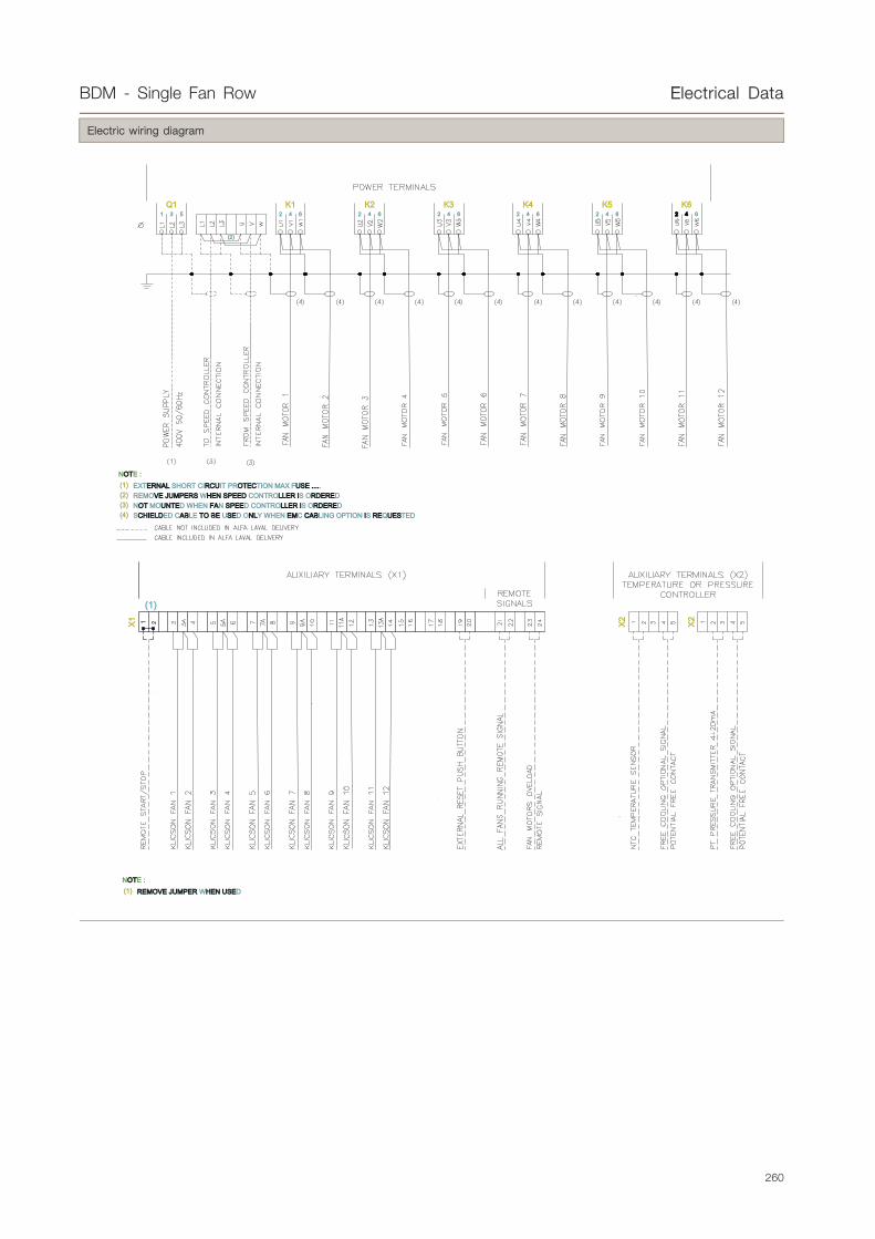
Electric wiring diagram
(2) REMOVEVE JUMPERSJUMPERS WHENHEN SPEEDSPEED CONTROLLLLERER IIS ORDERERDERED
Q1 K1 K2 K3 K4 K5642642642642642531
NOTOTE :(1) EXTERNALERNAL SHORT CIRCURCUIT PROTOTECECTION MAX FUSEUSE .........
(2)
K62 42 4 6
(3) NOTOT MOUNUNTETED WHEN FAFAN SPEESPEED CONTROLLLLERER IIS ORDERERDERED(4) SCHCHIEIELDLDED CABABLE TOTO BEBE USESED ONLNLY WHEN EMEMC CABCABLING OPTION IIS REREQUESUESTED
(1)
NOTOTE :(1) REMOVEREMOVE JUMPERJUMPER WHENHEN USEUSED
X1
X2
X2
260

BDM - Single Fan Row EElectrical Data
.
Switch Board (Control Panel)
Function
Basic Version for Vertical Installation
General data
Cabinet Material: Sheet steel 15/10mm zinc-coated
Internal Plate: Sheet steel 20/10mm zinc-coated
Protection Class: IP 55
Cabinet Colour: RAL 7035, light grey polyester paint
Cabinet Doors: Opening angle 110°
Ambient Temp.:• min. -10°C, max. +35°C standard• min. -25°C, max. +35°C with electrical heater• min. -10°C, max. +50°C with cooling fan• min. -25°C, max. +50°C with heater and fan
Cables included: Bottom position with cable glands.
Dimensions
0
M20
M25
M20 M20M32
M20
M12
M25
M25 M20 M20 M20
GRID
GRID
261

BDM - Single Fan Row EElectrical Data
Electric wiring diagram
(2) REMOVEVE JUMPERSJUMPERS WHENHEN SPEEDSPEED CONTROLLLLERER IIS ORDERERDERED
Q1 K1 K2 K3 K4 K5642642642642642531
NOTOTE :(1) EXTERNALERNAL SHORT CIRCURCUIT PROTOTECECTION MAX FUSEUSE .........
(2)
K62 42 4 6
(3) NOTOT MOUNUNTETED WHEN FAFAN SPEESPEED CONTROLLLLERER IIS ORDERERDERED(4) SCHCHIEIELDLDED CABABLE TOTO BEBE USESED ONLNLY WHEN EMEMC CABCABLING OPTION IIS REREQUESUESTED
(1)
NOTOTE :(1) REMOVEREMOVE JUMPERJUMPER WHENHEN USEUSED
X1
X2
X2
262

BDM - Single Fan Row EElectrical Data
.
Current Distribution
Function
Current distributors are available as optional accessories. Numerous fans can be connected. In combination with Fcontrol frequency inverters,
we can deliver the current distribution with both main switch and bypass function. Features: The current distributor is equipped with plastic
housing IP54 and motor protection units STDT16E with status signal contacts ZB. It is possible to lock the motor protection units with a
padlock and use them as repair switches. Fans are directly connected to the motor protection units. Line protection is guaranteed through
the integrated short-circuit release. Terminals for supplying the controller output are also integrated. The current distributors are suitable for
external mounting (e.g. direct mounting at refrigeration units). It’s easy to see the switch position of the motor protection units through the
coloured, transparent plastic door.
General data
Current distributor with main switch and bypass function:• The controller is supplied by the current distributor• Main switch: 100% - 0 -1• In position 100%, the connection to the controller output is switched off. This version is for Fcontrol frequency inverters .• Rated current: Up to 80A
Dimensions
440
164
15
5,5
570
275 140
45°
440
269
15
5,5
45°
570
380
Electric wiring diagram
Mains
Mainsupply
con
nec
tio
n o
f th
e m
oto
rsd
irec
tly
to t
he
mo
tor
pro
tect
ion
un
its
STD
T16E
Motors
to themotors
Current distribution with main switchand manual bypass
Inp
ut
con
tro
lled
volt
age/
freq
uen
cy
Motor
Main switch
Controller
Ou
tpu
t m
ain
s
Mains Mains
Onsite:Controller
e.g. Fcontrol,Dcontrol, Ucontrol
con
tro
lled
ou
tpu
tvo
ltag
e/fr
equ
ency
Motor
anal
og
Inp
ut
Signal
Sensor
263

BDM - Single Fan Row EElectrical Data
.
Frequency Converter (Inverter)
Function
Frequency inverter (incl. sine filter) for 3~ motors. Universal controller for refrigeration and air conditioning line input 3~ 208-480V, housing
IP54, internal display.• Speed controller with manual adjustment of output voltage at the unit or via external signal, 2-step operation;• Temperature control for liquid coolers;• Pressure control refrigeration (input for refrigerant) for: condensers, dual-circuit condensers;
General data
Equipment/Function• Integrated SINEFILTER between phase to phase and phase to earth.• Absolute parallel operation of fans, with no risk of damage to the motor. Screened motor cables are not required.• Integrated process controller (PID free programmable).• LCD multifunction display with plain language text.• 2x Analogue Input (0-10 V, 0-20 mA, 4-20 mA, temperature sensor type TF):
- Analogue 1 for setting of sensor signal.- Analogue 2 programmable function for: external set-point, difference value to sensor 1, comparison value (dual-circuit condenser),
averaging, and setpoint lowering according to outdoor temperature.
• 1x output 0-10V, programmable function: Constant voltage, proportional modulation, proportional input signal, group control, controller 2.• 2x digital inputs, programmable function: enable (on / off), external fault, limit output, input 1/2, set-point 1/2, setting internal / external,
automatic control / speed manual, reverse control function (“heating” / “cooling”), reset, setting max. speed.• 2x relay outputs, programmable function: operating indication, fault indication, external fault from digital input, limit modulation, limit input
signal, limit offset (deviation actual value setpoint), group control .• Total motor protection using thermocontact / thermistor connection.• Interface system with RS485 Interface (MODBUS) or LON® is another alternative option.
Technical data• Line voltage 3~ 208 BND_480V (-15% / +10%), 50/60Hz.
Rated current*/A 4 8 13 18 22 32 40
Max. line fuse/A 10 10 16 20 25 35 50
Max. heatdissipation*/W 130 210 350 440 540 950 1.100
Weight/Kg 8.8 9.0 22.8 25.4 28.1 29.5 31.8
*at line voltage 400V / 50Hz (for FXDM40A rated current - only possible for fans with cos < 0.8).
• Maximum output frequency 100Hz (for FXDM40, max. 60Hz).• Clock frequency 16 kHz.• Max. permissible ambient temperature 40°C (up to 55°C with derating).• Voltage supply for sensors +24V ±20% (Imax. 120 mA).• Permissible rel. humidity 85% with no condensation .• Interference emission EN 61000-6-3 1 (unshielded motor cable).• Interference immunity EN 61000-6-2.
Settings• Quick start-up with pre-programming modes.• Set-point 1, set-point 2, manual mode.• Min. and max. speed, speed limitation e.g. for night operation.• Group control (via relay or 0-10V signal output).• Limits: Modulation, input signal, offset (deviation set to actual value).• Set protection, save user settings.• Readout events memory (checking the fault log).• Masking up to 3 settable speed ranges.• Minimum rate of air on / off.• Edge frequency, max. frequency / voltage, start voltage.• U/f characteristics: quadratic or linear.• Menu language: English, German, Italian, Swedish, etc.• Inverting: Inputs analogue and digital, analogue out, relays.
264
BDM - Single Fan Row EElectrical Data
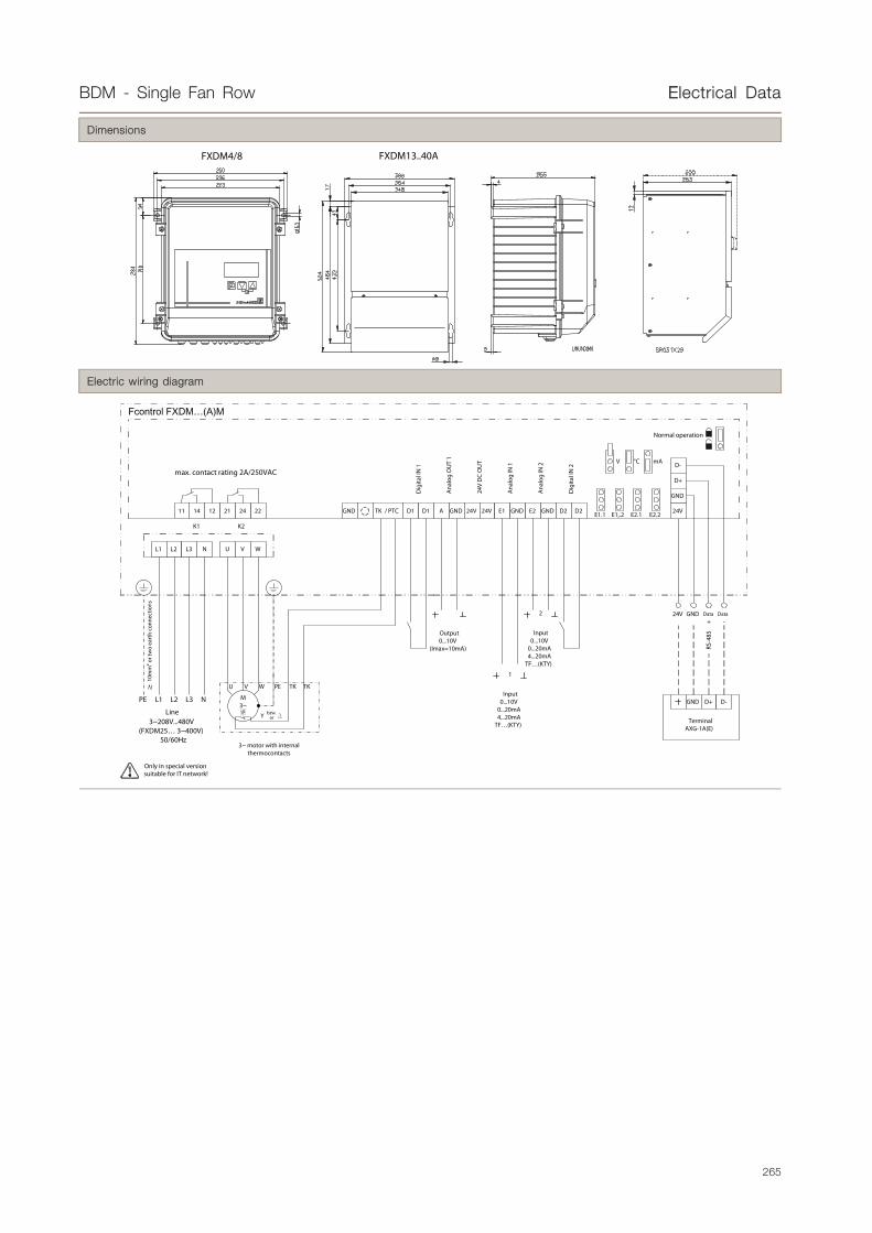
Dimensions
FXDM4/8 FXDM13..40A
Electric wiring diagram
3~ motor with internal thermocontacts
M3~
PEV WU TK TK
Y Dbzw.or
121411
NL1 L2 L3
L3 NL2L1PE
Line3~208V...480V
(FXDM25… 3~400V)50/60Hz
222421 GND A GND 24V 24V E1 GND E2D1 D1 GND D2 D2 E2.2E2.1E1,.2E1.1
D-
D+
GND
U V W
Dig
ital I
N 1
Ana
log
OU
T 1
24V
DC
OU
T
Ana
log
IN 1
Ana
log
IN 2
Dig
ital I
N 2
Data DataGND+ -
Output0...10V
(Imax=10mA)
Input0...10V
0...20mA4...20mA
TF…(KTY)
Input0...10V
0...20mA4...20mA
TF…(KTY)
1
2
10m
m2 o
r tw
o ea
rth
conn
ectio
ns
max. contact rating 2A/250VAC
K1 K2
V °C mA
GND D+ D-
TerminalAXG-1A(E)
24V
24V
TK / PTC
RS-4
85
Only in special version suitable for IT network!
Normal operation
265

BDM - Single Fan Row CCode description
.
kyBDM - Single Fan Rowky Code description
Code No. 1 2 3 4
BDM S 63 2 A
1) Type of noise level (number of dB(A) to reduce compared with "base" version)
Turbo noise level Standard noiselevel
Low noiselevel Quiet noise level Residential
noise level
T S* L* Q* R*
Fan diameter Ø 630mm (normal / long) - base -10 -18 -29
Fan diameter Ø 800mm - base -7 -16 -20
Fan diameter Ø 910 mm base -2 -9 -19 -20
Fan diameter Ø 1 000 mm - - base -14 -16
2) Fan diameter Ø
63 630 mm
80 800 mm
90 910 mm
100 1 000 mm
3) Number of Fans (* available in this version)
Fan diameterØ 630mm
Fan diameter Ø630 mm
Fan diameter Ø800mm
Fan diameterØ 910 mm
Fan diameter1000mm
1 * * * * *
2 * * * * *
3 * * * * *
4 - * * * *
5 - - * - -
4) Number of coil rows
A 2
B 3
C 4
D 5
General Alfa Select Air LegendDescription 1 Description 2
D D fan cabling (three phase) BBSFT Basic Switch Board + Speed Control Temp. + Signal AAL Aluminium finY Y fan cabling (three phase) BI Basic Switch Board + Frequency Converter (Inverter) CCU Copper fin
D/Y D/Y fan cabling (three phase), single speed fan motor BBSI Basic Switch Board + Frequency Converter (Inverter) + Signal PR Pre-coated finS Single phase CC Switch Board + Cooling fan SSS Stainless steel tubeP Packaged on a pallet RR Switch Board + Resistor TH Thermoguard treatment
CR Packaged in a crate FF Switch Board + Cooling fan + Resistor CCF Cataphoresis treatmentBO Packaged in a box PPT Ammonia pump top SC Sub-cooling circuitFeet Feet-mounted PPB Ammonia pump bottom kkW Spray water kitSW Safety Switch AL Aluminium casing FFL FlangesCB Terminal Box SS Stainless Steel casing FH Fan ring heaterB Basic Switch Board AP Pre-painted Aluminium casing IS Insulated Drip Tray
BS Basic Switch Board + Signal PL Plastic casing RRH Reheating coilBP Basic Switch Board + Step Control Pressure EE Electrical defrost SR Air socket adapter ringPT Basic Switch Board + Step Control Temperature LE Low Electrical defrost CW Air throw fan cowling
BSP Basic Switch Board + Step Control Pressure + Signal A Air Defrost EER 120° elbow reducerBST Basic Switch Board + Step Control Temp. + Signal HG Hot Gas Defrost HN Hinged fan cowlingBFP Basic Switch Board + Speed Control Pressure HHG+E Hot Gas Defrost + Electrical Defrost on drip trayBFT Basic Switch Board + Speed Control Temperature W Water Defrost
BSFP Basic Switch Board + Speed Control Pres. + Signal WW+E Water Defrost + Electrical Defrost on drip trayNote: valid for the entire product range
266