evaporation/boiling on thin capillary wick (ii): … on thin...evaporation/boiling on thin capillary...
TRANSCRIPT

University of South Carolina College of Engineering and Computing Mechanical Engineering Department
Evaporation/boiling on Thin Capillary
Wick (II): Effects of Volumetric Porosity
and Mesh Size
Chen Li and G. P. Peterson

Chen LiGraduate Research Assistant
Rensselaer Polytechnic Institute,
Department of Mechanical, Aerospace and
Nuclear Engineering
Troy, NY 12180
e-mail: [email protected]
G. P. PetersonProfessor and Chancellor
University of Colorado,
Boulder, CO 80309
e-mail: [email protected]
Evaporation/Boiling in ThinCapillary Wicks „II…—Effectsof Volumetric Porosityand Mesh SizePresented here is the second of a two-part investigation, designed to systematically iden-tify and investigate the parameters affecting the evaporation from and boiling within, thincapillary wicking structures with a range of volumetric porosities and mesh sizes. Theexperimental studies were investigated under steady-state conditions at atmospheric pres-sure. Part I of the investigation described the wicking fabrication process and experi-mental test facility, and focused on the effects of the capillary wick thickness (ASME J.Heat Transfer., 128, pp. 1312–1319). In Part II, we examine the effects of variations inthe volumetric porosity and the mesh size. The experimental results presented here indi-cate that the critical heat flux (CHF) was strongly dependent on both the mesh size andthe volumetric porosity; while the evaporation/boiling heat transfer coefficient was sig-nificantly affected by mesh size, but not strongly dependent on the volumetric porosity.The experimental results further illustrate that the menisci at the CHF are located in thecorners, formed by the wire and the heated wall and between the wires in both thevertical and horizontal directions. The minimum value of these three menisci determinedthe maximum capillary pressure generated through the capillary wick. The experimentalresults and observations are systematically presented and analyzed, and the local bubbleand liquid vapor interface dynamics are examined theoretically. Based on the relativerelationship between the heat flux and superheat, classic nucleate boiling theory, and thevisual observations of the phase-change phenomena, as well as by combining the resultsobtained here with those obtained in Part I of the investigation, the evaporation/boilingheat transfer regimes in these capillary wicking structures are identified and discussed.�DOI: 10.1115/1.2349508�
1 Introduction
Evaporation/boiling in capillary wicking structures has been
shown to be an effective heat transfer mechanism in a wide vari-
ety of applications, such as heat pipes, loop heat pipes �LHP�,capillary pumped loops �CPL�, etc. As a result, the parameters that
govern these phenomena are of considerable interest. A summary
of the recent investigation has been presented in Part I of this
two-part investigation �1�. In that review, the range of capillary
wick structures previously investigated was summarized, along
with the fabrication procedures used, the size of the heat source
employed, and the contact condition between the heated wall and
the capillary wick �2–12�. The resulting conclusions were that of
all the various parameters investigated to date, one of the most
critical parameters, the contact condition, was also the one most
often neglected. In Part I, the contact condition between the cap-
illary wicking structure and the heated surface was found to be a
key factor that affects both the heat transfer efficiency and the
CHF. In addition, the effects of capillary wick thickness on the
evaporation/boiling in capillary wicking structures made from
uniform layers of sintered isotropic copper mesh were also pre-
sented. The experimental results indicated that the sintering pro-
cess developed in Part I could achieve nearly perfect contact at the
heated surface/capillary wick interface. It was also demonstrated
that the evaporation/boiling heat transfer is nearly independent of
the capillary thickness, while the CHF increases with increasing
thickness, if all other geometric properties, i.e. volumetric poros-
ity and mesh size, were held constant. In Part I, extremely high
heat transfer performance and CHF values were successfully
achieved from thin capillary wicks fabricated from sintered iso-
tropic copper mesh. These structures achieved some of the highest
heat transfer enhancement and CHF values reported in the litera-
ture. In addition, this structure was easy to fabricate and allowed
precise control of both the thickness and volumetric porosity.
In addition to the effects of the capillary wick thickness, two
fundamental questions must be addressed before the evaporation/
boiling mechanism from these structures is fully understood.
These are: First, what is and where does the critical meniscus
radius, which is controlled by the wire diameter and the mesh
number, occur in these types of structures? And second, how does
the volumetric porosity affect the evaporation/boiling perfor-
mance, characteristics and CHF? For thin capillary wicking struc-
tures fabricated from sintered isotropic copper mesh, the critical
meniscus radius and the effective pore size in the liquid flow
direction are controlled by the mesh size �including wire diameter
and mesh number� and the compression factor. In �14� the value of
�W+d� /2 was recommended as the effective pore radius to esti-
mate the capillary pressure for multiple wire-mesh screens, forboth sintered and simple contact situations. Because theevaporation/boiling phenomenon is a complicated and dynamicprocess, the determination of the critical meniscus radius is quitechallenging. In the evaporation/boiling process from a capillarywicking structure, the menisci are initially formed at the horizon-tal mesh openings. As the heat flux increases, the evaporation atthe liquid-vapor interface is intensified. In these situations, theliquid meniscus recedes into the wick, reducing the meniscus ra-dius, which results in an increase in the capillary pressure. How-ever, in some cases, the capillary pressure generated through the
Contributed by the Heat Transfer Division of ASME for publication in the JOUR-
NAL OF HEAT TRANSFER. Manuscript received August 28, 2005; final manuscript re-
ceived January 11, 2006. Review conducted by Raj M. Manglik.
1320 / Vol. 128, DECEMBER 2006 Copyright © 2006 by ASME Transactions of the ASME

meniscus curvature may not be sufficient to drive or pump therequired amount of working fluid to the heating area. Visual ob-servations indicate that these menisci are not only formed at thehorizontal mesh openings, but may also be formed at other loca-tions in the capillary wick structure, i.e., the vertical mesh open-ings or the corners formed at the junction of the wire and theheating wall.
In the current investigation, the effects of the critical meniscusradius/the effective pore size and volumetric porosity are investi-gated systematically by varying the mesh size including the wirediameter and mesh number, and the distance between wire layers,respectively. This approach provides new physical insights intothe evaporation/boiling phenomena from the capillary wickingstructures. To accomplish this, the optimum sintering process de-veloped in Part I �1� was employed to minimize the contact ther-mal resistances between the individual layers of copper mesh, aswell as between the copper mesh and the heated wall. All of theexperimental results presented herein utilized an identical sinter-ing process.
The literature review indicates that heat transport models andregimes for evaporation/boiling from capillary wicking structureshave been studied by a number of investigators. Hanlon and Ma�9� studied evaporation on sintered copper particle beds, both ana-lytically and experimentally. This study indicated that there existtwo heat transfer models: one for thin liquid film evaporation andone for nucleate boiling; that the thin film evaporation heat trans-fer on the top surface of the wick is the dominant factor in theenhancement of the evaporating heat transfer, and that nucleateboiling causes a decrease in heat transfer performance. The heattransfer models for heat pipes shown later as Fig. 11 were pre-sented and discussed by Faghri �14�. Four models were presentedand discussed: conduction-convection, receding liquid, nucleateboiling, and film boiling. In addition, the dynamics of the liquid-vapor interface and its effects on the evaporation/boiling in capil-lary wicks were mentioned indirectly. In the following, visual ob-servations and analytical analyses, along with the heat transferregimes, local bubble dynamics, and liquid vapor interface dy-namics are all systematically presented and discussed.
2 Results and Discussion
All of the experiments were conducted using the experimentaltest facility and test procedures described in Part I �1�. Specifica-tions of the test samples used in the current investigation are listedin Table 1. Typical test results are summarized in this section andare presented in terms of the heat flux including the CHF, wallsuperheat, and heat transfer coefficient.
2.1 Effects of Mesh Size. To investigate the effects of varia-tions in the mesh size on the evaporation/boiling heat transferperformance and CHF at steady-state condition, three test articles,E145-4, E100-2 and E60-1, with approximately identical thick-nesses and volumetric porosities, were evaluated in an atmo-spheric environment. For comparisons, the pool boiling curve on a
plain surface is added in Figs. 1�a� and 1�b�.
2.1.1 Effects of Mesh Size on Evaporation/Boiling HeatTransfer Performance. Figure 1�a� presents the heat flux as afunction of the superheat, while Fig. 1�b� illustrates the effectiveheat transfer coefficient. As shown, the evaporation/boiling heattransfer coefficient increases with incremental increases in the in-put power until a maximum value has been reached. At this pointthe evaporation/boiling heat transfer coefficient begins to de-crease, due to partial dry out of the wick structure and the heatedsurface. This implies that the capillary force is still effective inhelping to provide fluid to the heated area even at partial wick dryout, which is consistent with the findings of the experimental in-vestigation in Part I �1�. Furthermore, the heat transfer perfor-
mance on the 2362 m−1 copper mesh �60 in.−1�, a relatively
coarse mesh, reached values as high as 117.3 kW/m2 K, which isstill superior to pool boiling on a plain surface.
With the exception of the initial region and the region following
partial dry out, the input heat flux, q�, and the wall super heat,
TW−Tsat, exhibit a strong linear relationship. Figure 1�a� also in-dicates that the evaporation/boiling heat transfer performance ofthe capillary wick increases with increasing mesh number or de-creases in the mean pore size. While it is clear that both the totalsurface area and the exposed surface area would increase propor-tionally with an increase in the mesh number, an increase in thetotal surface area or an increase in the exposed surface couldaccount for the increase in the heat transfer coefficient with wirediameter. However, in Part I �1� it was illustrated that only the
Table 1 Specification of the test samples
Sample # Wire diameter ��m� Porosity Pore size ��m�
E145-4 56 0.692 119.3E145-6c 56 0.56 119.3E145-7c 56 0.409 119.3E100-2 114 0.632 139.7E60-1 191 0.67 232.8E145-8
a56 0.698 119.3
aThis sample is 0.74 mm thick
Fig. 1 „a… Heat flux as a function of superheat †Twall−Tsat‡ as afunction of mesh size; „b… heat transfer coefficient as a functionof heat flux as a function of mesh size
Journal of Heat Transfer DECEMBER 2006, Vol. 128 / 1321
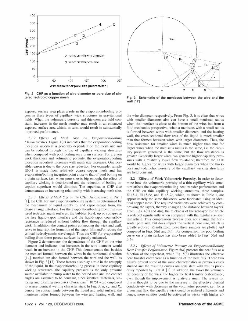
exposed surface area plays a role in the evaporation/boiling pro-cess in these types of capillary wick structures in gravitationalfields. When the volumetric porosity and thickness are held con-stant, increases in the mesh number may result in an enhancedexposed surface area which, in turn, would result in substantiallyimproved performance.
2.1.2 Effects of Mesh Size on Evaporation/BoilingCharacteristics. Figure 1�a� indicates that the evaporation/boilinginception superheat is generally dependent on the mesh size andcan be reduced through the use of capillary wicking structureswhen compared with pool boiling on a plain surface. For a givenwick thickness and volumetric porosity, the evaporation/boilinginception superheat increases with mesh size increases. One pos-sible reason is due to the pore size reduction. For example, sampleE60-1 is made from relatively coarse copper mesh and hasevaporation/boiling inception point close to that of pool boiling ona plain surface, i.e., when pore size is big enough, the effect ofcapillary wicking is deteriorated and the reduction of boiling in-ception superheat would diminish. The superheat at CHF alsodemonstrates an increasing relationship with increasing mesh size.
2.1.3 Effects of Mesh Size on the CHF. As discussed in Part I�1�, the CHF for any evaporation/boiling system, is determined bythe mechanism of liquid supply to, and vapor escape from, thephase change interface. For the evaporation/boiling from thin sin-tered isotropic mesh surfaces, the bubbles break up or collapse atthe free liquid-vapor interface and the liquid-vapor counterflowresistance is reduced without bubble flow through the capillarywick. In addition, the contact points connecting the wick and wall,serve to interrupt the formation of the vapor film and/or reduce thecritical hydrodynamic wavelength. Thus the CHF for evaporation/boiling from these porous surfaces is greatly enhanced.
Figure 2 demonstrates the dependence of the CHF on the wirediameter and indicates that increases in the wire diameter wouldresult in an increase in the CHF. This demonstrates that besidesthe menisci formed between the wires in the horizontal direction�14�, menisci are also formed between the wire and the wall, asshown in Fig. 3 �17�. These factors also play a role in the resupplyof the liquid. In the evaporation/boiling process in these capillarywicking structures, the capillary pressure is the only pressuresource available to pump water to the heated area and the contactangles are assumed to be constant, since identical materials, sin-
tering and cleaning processes �Duraclean™ 1075� were employed
to assure identical wetting characteristics. In Fig. 3, �, rm, and Rw
denote the contact angle between the liquid and solid surface, themeniscus radius formed between the wire and heating wall, and
the wire diameter, respectively. From Fig. 3, it is clear that wireswith smaller diameters also can have a small meniscus radiuswhen the interface is close to the bottom of the wire, but from afluid mechanics perspective, when a meniscus with a small radiusis formed between wires with smaller diameters and the heatingwall, the cross-sectional flow area of the liquid is much smallerthan that formed between wires with larger diameters. Thus, theflow resistance for smaller wires is much higher than that forlarger wires when the meniscus radius is the same, i.e. the capil-lary pressure generated is the same, but the flow resistance isgreater. Generally larger wires can generate higher capillary pres-sures with a relatively lower flow resistance; therefore the CHFwould be higher for wires with larger diameters when the thick-ness and volumetric porosity of the capillary wicking structuresare held constant.
2.2 Effects of Wick Volumetric Porosity. In order to deter-mine how the volumetric porosity of a thin capillary wick struc-ture affects the evaporation/boiling heat transfer performance andthe CHF on thin capillary wicking structures, three samples,E145-4, E145-6c, and E145-7c, which, as shown in Table 1, areapproximately the same thickness, were fabricated using an iden-tical copper mesh. The required variations were achieved by com-pressing the layers, thereby changing the distance between layers.From Figs. 4�a� and 4�b�, the thickness of the six-layer test articleis reduced significantly when compared with the regular six-layertest article. This compression process does not change the hori-zontal pore size, but does impact the vertical pore size, which isgreatly reduced. Results from these three samples are plotted andcompared in Figs. 5�a� and 5�b�. For comparison, the pool boilingcurve on a plain surface has also been added to Figs. 5�a� and5�b�.
2.2.1 Effects of Volumetric Porosity on Evaporation/BoilingHeat Transfer Performance. Figure 5�a� presents the heat flux as afunction of the superheat, while Fig. 5�b� illustrates the effectiveheat transfer coefficient as a function of the heat flux. These twofigures present some of the same characteristics as previous casesstudied and the resulting curves are consistent with results previ-ously reported by Li et al. �1�. In addition, the lower the volumet-ric porosity of the wick, the higher the heat transfer performance,even though the improvement is relatively small. The reason forthis is thought to be due to the increase in the effective thermalconductivity with decreases in the volumetric porosity, i.e., for agiven heat flux, the capillary wick could be utilized efficiently andhence, more cavities could be activated in wicks with higher ef-
Fig. 2 CHF as a function of wire diameter or pore size of sin-tered isotropic copper mesh Fig. 3 Schematic of the meniscus between the wire and the
wall †17‡
1322 / Vol. 128, DECEMBER 2006 Transactions of the ASME

fective thermal conductivities. Generally, for porous media withthe same structure, the effective thermal conductivity increaseswith decreases in the volumetric porosity.
It is also apparent that wicks with a lower volumetric porositywould result in higher heat flux values after partial dry out. This isbecause the pore size in the vertical direction becomes smallerafter compression, resulting in a smaller capillary radius andhence, a higher capillary pressure. This explains the existence ofan optimum porosity when the wick thickness and mesh size areboth held constant.
Figure 5�a� clearly indicates that the evaporation/boiling incep-tion point is greatly reduced when compared with pool boiling ona plain surface and can be shown to be independent of the volu-metric porosity for a given mesh size and capillary wick thick-ness.
2.2.2 Effects of Volumetric Porosity on the CHF. Mathemati-cally there exist three distinct cases for volumetric porosity: aregular capillary wick covered surface, a solid coated surface, andan empty coated surface, each distinguished by the relative poros-ity of the coating material or wick. This experimental study inves-tigated the effects of porosity, which varied from 0.409 to 0.692by changing the distance between the wires in the vertical direc-
tion. For �=0, the heating area is filled with solid metal and thusno phase change can occur on top of the heated wall without the
liquid supply. For this case, the CHF is assumed to be 0 W/cm2.However, when the heating area becomes empty and a pool ofliquid is formed above the top of the heater, the CHF is similar tothe value obtained for pool boiling in �1�. This experimentallymeasured value in Part I is presented here in Fig. 6.
Figure 6 illustrates that for a given thickness and mesh size,there exists an optimum volumetric porosity that governs the CHF
and evaporation/boiling from thin capillary wicks made of sin-tered isotropic copper mesh. From a fluid mechanics perspective,increases in the volumetric porosity results in a decrease in theflow head loss. If the maximum capillary pressure generated in thewick is dependent only on the wire diameter and horizontal poresize �14�, the CHF would increase with increases in the wickvolumetric porosity, because of a decrease in the flow resistance.
Fig. 4 „a… SEM image of the compact six layer sample; SEMimages of sintered isotropic copper mesh with 1509 m−1
„145 in.−1…, 56 �m „0.0022 in. … wire diameter, and fabricated atsintering temperature of 1030 °C with gas mixture protection„75% N2 and 25% H2… for two hours
Fig. 5 „a… Heat flux as a function of superheat †Twall−Tsat‡ as afunction of volumetric porosity; „b… heat transfer coefficient asa function of heat flux as a function of volumetric porosity
Fig. 6 Test data of CHF as a function of volumetric porosity ofthe sintered isotropic copper mesh
Journal of Heat Transfer DECEMBER 2006, Vol. 128 / 1323

However, as shown in Fig. 6, the CHF decreases after a volumet-ric porosity of approximately 0.50, which implies an optimumvolumetric porosity in the present capillary wick structure. Fur-thermore, the existence of an optimum volumetric porosity im-plies that the menisci formed between the wires in the verticaldirection also play an important role in the capillary pressure gen-eration. From this analysis and the discussion in Sec. 2.2.3, it isapparent that the minimum meniscus radius, which can occur atthe pores between the wires in the horizontal direction or thevertical direction, as well as between the wire and the wall, deter-mines the capillary limit in evaporation/boiling from capillarywick surfaces.
3 Evaporation/Boiling on Thin Capillary Wicks
3.1 Heat Transfer Regime on Thin Capillary Wicks. Theresults presented in Part I, coupled with the previous discussions,illustrate the characteristics of evaporation/boiling from uniformlysintered copper mesh coated surfaces. It is important to under-stand what happens in this complex process, in order to optimizethe use of these structures in actual applications. Evaporation/boiling phenomenon on uniformly sintered copper mesh surfacesis complicated by the existence of several different regimes andirregular geometric characteristics of the liquid-vapor interface.Based on visual observations of the phase change phenomenon
and comparisons of the experimental test data, characteristic q�-
Tsuper and h-q� curves have been proposed, as shown in Figs. 7�a�and 7�b�, respectively. These two curves clearly demonstrate thethree regimes that exist: convection, nucleate boiling and thin film
evaporation. The transition from one regime to another is accom-panied by marked changes in the hydrodynamic and thermal statesof the system. When the temperature or heat flux is below a cer-tain value �i.e., the onset of strong nucleate boiling�, heat is trans-ferred by convection �AB�, which is driven by the temperaturedifference or a small number of relatively large bubbles. This,then transitions to a region where the nucleate boiling �CD� is thedominant heat transfer mechanism when the temperature or heatflux exceeds the saturation temperature by a value that varies withthe capillary wick thickness, pore size and surface characteristics.In Figs. 7�a� and 7�b�, the transition region, BC, does not actuallyexist. The wall temperature effectively jumps from B to C when itexceeds the evaporation/boiling inception point. In the nucleateboiling regime, numerous bubbles are generated and grow fromthe nucleation sites on the heated surfaces, i.e. heater wall andwire surfaces, and finally break up or collapse at the free liquid-vapor interface. Increases in the wall temperature or heat flux areaccompanied by large increases in the bubble population. Theseprocesses, as well as the mutual interaction among bubbles andnucleation sites, result in significant enhancement in the heattransfer performance. It is worth noting that the capillary evapo-ration also plays an important role in the improvement of perfor-mance in the nucleate boiling regime. If the temperature or heatflux is further increased, the meniscus recedes further into theporous material and thin liquid film evaporation �DE� begins. Inthis region, the liquid film thickness becomes very thin due to acombination of the surface tension and disjoining pressure, mak-ing it very hard for bubbles to form and grow from the heatedsurfaces, and hence, the liquid just evaporates directly from theheated surfaces until they dry out completely, which results in thebest performance among these three regimes.
3.2 Onset Point of Nucleate Boiling From a HorizontalHeated Wall. As was the case for pool boiling, in order to reachnucleate boiling, the surface temperature must exceed the satura-tion temperature by several degrees. Based on the previous dis-cussions, this onset of nucleate boiling from sintered copper meshsurfaces varies with the thickness and mesh size, and is nearlyindependent of the volumetric porosity. Figure 8 presents the su-perheat of the heated wall as a function of the heat flux applied, asin the cases of E145-4, 6, and 8. When the wall temperature islower than the onset of nucleate boiling, it increases with heatflux; however, once it exceeds that critical value, nucleate boilingbegins and the wall temperature drops sharply due to the high heattransfer capability of nucleate boiling. Figure 8 demonstrates thetransition from convection heat transfer to nucleate boiling heattransfer that occurs on sintered copper mesh surfaces, which can
be easily identified on either a typical q�-Tsuper or heff-q� curve,i.e., point B to C. This figure also illustrates that nucleate boiling
Fig. 7 „a… Typical q�-Tsuper curve for evaporation/boiling pro-cesses from uniformly sintered copper mesh surfaces „b… Typi-cal heff-q� curve for evaporation/boiling process from uniformlysintered copper mesh surfaces
Fig. 8 Onset point of nucleate boiling for evaporation/boilingprocesses from uniformly sintered copper mesh surfaces
1324 / Vol. 128, DECEMBER 2006 Transactions of the ASME

occurs in the capillary wicks and significantly improves the heattransfer performance, which is different from the findings of Han-lon and Ma �9�.
For some surfaces, section AB can be easily overlooked be-cause the value of the onset of nucleate boiling is small and is noteasily predicted. In addition, in some cases the step increase of theheat flux used may be larger than the value at which the onset ofnucleate boiling occurs, making it impossible to distinguish oneregion from another.
The reason that the superheat necessary to activate nucleateboiling varies with the capillary wick thickness and mesh size,remains somewhat unclear. The current experimental investigationonly illustrates that these phenomena do, in fact, occur forevaporation/boiling on the capillary wick. The available data in-dicate that the onset point of nucleate boiling increases with de-creases in the mesh size and thickness, but this appears to have nodirect relationship with the capillary wick volumetric porosity.
3.3 Local Bubble Generation from a Horizontal HeatedWall. From classical nucleate boiling theory, it is clear that thecharacteristics of the actual surface are very complicated and thatthe many nucleation cavities with various shapes and sizes allaffect the boiling characteristics. Bubbles are typically generatedfrom the largest cavities first, since this process requires less en-ergy, with the smaller cavities subsequently activated as the heatflux increases. Although the mechanisms of bubble generationfrom sintered copper mesh surfaces agree with the classicaltheory, there appears to be some subtle influences due to the pres-ence of the capillary wicking structure that should be noted.
Inside the sintered copper mesh, there are a variety of differenttwo-dimensional menisci formed at the various corners, due to thesurface tension. The liquid-phase pressure that exists prior to thinliquid film evaporation in this kind of porous media is determinedby the capillary forces generated at the different menisci, and thethin liquid film thickness is determined by the disjoining pressure.Since copper, when treated as described herein, wets well withwater, the pressure in the cavity is given by Eqs. �1� and �2�:
Pv
= Pl + 2�/r �1�
Pl = Patm − 2�/rm �2�
where r and rm are the radius of the curvature of the bubbleinterface and meniscus, respectively.
Equations �1� and �2� indicate that both the liquid pressure andthe liquid thickness would decrease as the size of the meniscusradius decreases. The local evaporation/boiling process on the uni-formly sintered copper mesh coated surface has five typical con-
figurations, as illustrated in Fig. 9: the initial state �a�, convection
�b�, nucleate boiling �c�, thin liquid film evaporation �d�, and dry
out �e�. In this process, water is supplied only via the capillary
forces, which can be deduced from the surface tension and thegeometric parameters of the meniscus. At a lower heat flux,smaller amounts of larger bubbles are generated and grow withinthe heated liquid. In addition, a thin liquid film is formed on theupper wire surfaces. In most cases, boiling and evaporation occursimultaneously and the bubble movement causes liquid convec-tion. If the heat flux increases, the meniscus radius must decreasein order to provide the capillary force needed to pump water intothe heated area. Thus, the bubble population and bubble genera-tion frequency, as well as the thin liquid film area all increase. Asthe heat flux continues to increase, the meniscus radius recedestowards the corner along the solid heated surfaces, forming a thinliquid film, which, due to the disjoining pressure makes it difficultfor a bubble to form and grow. At this point, liquid film evapora-tion becomes the dominant mode. If the heat flux continues toincrease, the central portion of the mesh will dry out, due to a lossof liquid supply.
3.4 Local Bubble Dynamics From the Heated Surface. Themost noticeable difference between classical nucleate boiling in
pool boiling and the evaporation/boiling processes from a thin,
i.e., less than 1 mm, sintered copper mesh, is that in the latter, thebubbles never grow large enough to release, hence, there is nobubble departure from the horizontal heated wall. Generally, thebubble departure diameter is estimated by
Dd = Bo1/2� 2�
g��l − �v��1/2
�3�
The Bond number depends on the bubble contact angle andstochastic processes; i.e., in actuality the observed bubble depar-ture diameter has a statistical distribution around some mean. Nu-merous investigations over the past 70 years have been carried outto estimate the Bond number. This departure diameter model wasfirst proposed by Fritz �13� and is shown below as Eq. �4�,
Dd = Cd�� 2�
g��l − �v��1/2
. �4�
Two more models are selected to compare with the model of Fritz.One model was developed by Cole and Rohsensow �13� and isshown as Eq. �5� below
�g��l − �v�Dd
2
��1/2
= Cd���lCplTsat
�vhfg
�5/4
�5�
where Cd=0.0148 for hydrogen bubbles and water vapor, in wa-
ter, and the contact angle, �, is in degrees. Here, Cd�=1.5�10−4
for water. The second model presented here was proposed byJensen and Memmel �15�.
Bo1/2 = 0.19�1.8 + 105K1�1/2 �6�
where, in Eq. �6� K1= �Ja/Prl���g�l��l−�v� /�l
2��� /g��l
−�v��3/2�−1 and the Jacob number, Ja, is defined by �TW
−Tsat�Cpl�l / ��vhfg�. For copper-water combinations, the contact
angle � is 55°, which was experimentally determined by Wu andPeterson �16�. The departure diameters estimated using Eqs.
�4�–�6�, for this situation are all greater than 1 mm. These estima-tions are listed in Table 2, where the minimum value given is evengreater than the thickest capillary wick presented herein,
0.82 mm.The typical localized bubble generation and growth from the
heated surfaces, i.e., the top wall of the heater and wire surfaces,are illustrated in Fig. 10. When a relatively low heat flux is ap-plied, only large cavities are activated, so large bubbles are gen-erated and grow from the heated surface. These large bubblesgrow, but never depart from the heated wall. Instead, they collapseat the free liquid-vapor interface, due to local condensation andpressure differences before they can grow large enough to gain
Fig. 9 Local evaporation/boiling processes from wire surfacesand the corners between the wire and the heated surface
Journal of Heat Transfer DECEMBER 2006, Vol. 128 / 1325

sufficient buoyancy energy to detach from the wall surface. Ahigher heat flux activates smaller cavities, and causes an increasein the number of bubbles and a decrease in the average bubblesize. The mutual interaction among bubbles results in higher heattransfer performance. With a further increase in the heat flux, themean bubble size continues to decrease and the bubble generationfrequency increases dramatically. In addition, for thin liquid filmswith high pressures �induced by the disjoining forces�, it is hardfor the bubbles to grow, and as a result, the liquid evaporatesdirectly from the thin liquid surface. In other words, when bubblescannot depart from the heated wall, there is a lower flow resis-tance between the bubble and the liquid, as well as a higherbubble generation frequency and the resulting heat transfer per-formance will be significantly enhanced.
3.5 Liquid Vapor Interface Dynamic and Drying-out Pro-cess on Thin Capillary Wicks. The behavior of the liquid-vaporinterface is one of the key characteristics that govern theevaporation/boiling on capillary wicking structures. In �14�, theheat transfer from capillary wicking structure surfaces was dis-cussed and four models were presented as shown in Fig. 11. Inaddition, the dynamics of the liquid-vapor interface and its effectson the evaporation/boiling in capillary wicks were discussed indi-rectly. The principal points in �14� can be summarized as follows:At low heat fluxes, combined conduction and convection is themain heat transfer mode and, if the wick is horizontal, the liquid-vapor interface is parallel to the heating surface. As the heat fluxincreases, the evaporation at the liquid surface is intensified, andthe liquid-vapor interface recedes uniformly, generating a greatercapillary force. In the receding liquid model, there is no boilingand conduction still governs the heat transfer across the liquidsurface. The capillary limitation may be encountered in this phase.When the heat flux is further increased, nucleate boiling may takeplace within the wick. Bubbles grow at the heated wall and escapeto the liquid surface, where they burst rapidly. Nucleate boilingmay represent a heat transfer limit in the nucleate boiling model,since, as the heat flux increases to a specific value, large quantitiesof bubbles are generated at the heated wall. These bubbles coa-lesce and form a vapor layer adjacent to the heated wall. Thisvapor layer is the principal cause of the heat transfer limit oftenencountered. In �14�, the heat transfer limit for evaporation incapillary wicks was described as being similar to that occurring inpool boiling heat transfer. The thickness factor was not consideredin �14� when evaporation/boiling behavior was discussed.
In the present work, however, the wick thickness is confined to
thicknesses of less than 1 mm, which is smaller than the bubble
departure diameter, Db. As discussed previously, at this thickness,a much higher heat transfer performance and higher CHF wereachieved. The control volume shown in Fig. 12 is utilized to ana-lyze the liquid vapor interface behavior in evaporation/boiling incapillary wicks. At saturation conditions, the mass and energyconservation equations can be defined as:
ml,in = ml,out + mv
�7�
hfg dmv
= q� dx �8�
Solving Eqs. �7� and �8�, the liquid-vapor interface configura-tion at steady state can be determined by
y = y0 −q�x
Glhfg
�9�
Here, Gl is the liquid flow rate and y0 is the initial position of
the liquid, i.e., the wick thickness. If the heat flux, q�, is ideallyuniform, the liquid-vapor interface would be a straight line with a
slope of −q� /Glhfg. However, because the thermal insulation isnot perfect, the actual heat flux profile along the heated wall isparabolic, as shown in Fig. 13. The interface would be irregulardue to the meniscus, but the overall shape would be curved, thin-ner in the center, and thicker at the edges. The overall liquid-vaporinterface dynamics has four typical modes, which are presented inFig. 14. Mode A is the initial state, in which the liquid-vaporinterface is parallel to the heated wall. As the heat flux is in-creased, vaporization begins and the meniscus begins receding,which generates a greater capillary force, increasing the amount ofliquid supplied to the heated area. The receding of the menisci is
Fig. 10 Local bubble dynamics and evaporation inevaporation/boiling processes on the surface
Fig. 11 Models of heat transfer and vapor formation in wicks†14‡
Fig. 12 Control volume of the liquid-vapor interface
Table 2 A comparison of the bubble departure diameter
Dd�mm�Fritz’s model �13� 2.884Cole and Rohsensow’s model �13� 2.426
Jensen and Memmel�15�
Tw-Tsat 1 K 1.032
5 K 1.169
15 K 1.482
30 K 1.897
1326 / Vol. 128, DECEMBER 2006 Transactions of the ASME

not uniform because of the constant and continuous liquid massreduction along the heated wall, which results from more vapor-ization of the liquid as the center of the heated area is approached.During this process, menisci are formed between the wires in thehorizontal and vertical directions, and even between the wire andthe heated wall after the initial dry out occurs.
This analysis is consistent with the experimental results pre-sented in Sec. 2.2.2. As the heat flux is further increased, thecurvature of the liquid-vapor interface becomes smaller and theinitial dry out point first appears at the center of the heated sectionof the wall. For evaporation/boiling on a capillary wick structure,the appearance of this initial dry out does not represent the CHF.The capillary wick will still function under higher heat fluxes untilsufficient liquid can no longer be provided. As shown in Fig. 15,the dry out regions are clearly evident for each of the differentheat flux levels tested. Here, the white rings represent the dry outregion for each heat flux level tested. At each heat flux, steady-state operation is achieved and a specified region of the wickremains dry. These rings represent the capillary limit for theevaporation/boiling in the capillary wick for a specified heat flux.
4 Conclusions
The minimum meniscus radius is ultimately the determiningfactor in CHF for the evaporation/boiling from capillary wickingstructures, and the results presented here illustrate that the menisci
are formed not just between the wires in the horizontal direction,but also between the wires in the vertical direction, and betweenthe wire and the wall. An optimal volumetric porosity has beenshown to exist for CHF in the capillary wicks, depending upon thethickness and mesh size. When the wire diameter and wick thick-ness are held constant, the experimental data shows that the heattransfer performance increases with decreases in the volumetricporosity of the wick, but the improvement is not significant. Thereason for this small improvement is thought to be due to theincrease in the effective thermal conductivity with decreases in theporosity, i.e., for a given heat flux, more cavities are activated inwicks with higher effective thermal conductivities.
Some key characteristics of the evaporation/boiling from capil-lary wicks are detailed in the discussion. When the capillary wick
thickness is less than 1 mm, the bubbles break up or collapse at
Fig. 13 Heat flux distribution along the flow direction of theheater
Fig. 14 Liquid-vapor interface and heat transfer model in thecapillary wick structure 1. distilled water; 2. copper wire; 3.liquid-vapor interface; 4. initial liquid-vapor interface position;5. interface position curve at uniform heat flux; 6. interface po-sition at actual heat flux; 7. vapor bubble; 8. first dry out point
Fig. 15 „a… Capillary wick surface before applied heat flux; „b… capillary wick after dry out. Progres-sive dry out processes in a capillary wick during evaporation/boiling
Journal of Heat Transfer DECEMBER 2006, Vol. 128 / 1327

the free liquid-vapor interface, due to local condensation and thepressure difference, instead of departing from the heated wall.This feature could enhance the heat transfer capability and CHFdramatically, due to reductions in the counterflow liquid and vaporresistance and the enhancement in the bubble generation fre-quency. Analysis of the liquid-vapor interface dynamics showsthat the liquid thickness in the wick, decreases nonlinearly alongthe heated wall, and the first dry out point occurs in the center ofthe heated area. This analysis also demonstrates that menisci areformed not just between wires in the horizontal direction, but alsobetween wires in the vertical direction and between wires and theheated wall. These new theoretical findings are consistent withboth the current and previously presented experimental results.
Both the experimental test data and the visual observations sup-port the concept that the heat transfer limit for evaporation/boilingin capillary wicks is the result of a capillary limit, and that thecharacteristic receding of the meniscus into the wick structure isnot uniform, but rather decreases as the center of the heated areais approached. The different heat transfer regimes for evaporation/boiling in these different capillary wick structures have been pro-posed and discussed based on the current and previous experimen-tal investigations as well as the visual observations of the phasechange phenomena and the heat flux—superheat relationship.
The test data obtained herein, illustrate that the evaporation/boiling inception is strongly dependent on the pore size in thehorizontal direction and the wick thickness, however, it is weaklydependent on volumetric porosity. Hysteresis was also observedfrom evaporation/boiling on the capillary wick in this experimen-tal investigation.
Acknowledgment
The authors would like to acknowledge the support of the Na-tional Science Foundation under award CTS-0312848. Fruitfuldiscussions offered by Dr. Ji Li and Mr. Hong Li are greatlyappreciated.
Nomenclature
A–E � points number in Fig. 3
Bo � Bond number
Cd � Constant in Eq. �3�Cd� � Constant in Eq. �4�Cp � Specific heat at constant pressure �J/kg.K�Dd � Bubble departure diameter �mm�G � Flow rate �kg/m2s�g � Gravitational acceleration �m/s2�
hfg � Latent heat �KJ/kg�Ja � Jacob number
K � Thermal conductivity �W/Mk�K1 � Parameter in Eq. �6�m � Mass flow rate �kg/s�M � Mesh number �m−1�O � Center of circle
P � Pressure �Pa�Pr � Prandtl number
q� � Heat flux �W/cm2�R � Bubble radius �mm�
rm � Meniscus radius �mm�R � Wire radius �mm�t � Distance or thickness �mm�
tw � Time required for bubble growth �s�td � Time required for bubble departure �s�T � Temperature �K�
W � Width of mesh opening
X � X coordinate
Y � X coordinate
Greek Symbols
� � Contact angle �degree� � Angle �degree�� � Volumetric porosity
� � Surface tension �N/m�� � Density �kg/m3�
Subscripts
in � Flow in direction
l � Parameter related to the liquid phase
out � Flow out direction
v � Parameter related to the vapor phase
w � Parameter related with the wall
sat � Parameter related with the saturation condition
eff � Effective parameter
References�1� Li, C., Peterson, G. P., and Wang, Y., 2006, “Evaporation/Boiling on a Capil-
lary Wick �I�—Wick Thickness Effects,” ASME J. Heat Transfer, 128, pp.
1312–1319.
�2� Liter, S. G., and Kaviany, M., 2001, “Pool-Boiling CHF Enhancement by
Modulated Porous-Layer Coating: Theory and Experiment,” Int. J. Heat Mass
Transfer, 44, pp. 4287–4311.
�3� Udell, K. S., 1985, “Heat Transfer in Capillary Wick Considering Phase
Change and Capillarity—The Heat Pipe Effect,” Int. J. Heat Mass Transfer,
28, pp. 77–82.
�4� Williams, R. R., and Harris, D. K., 2005, “The Heat Transfer Limit of Step-
Graded Metal Felt Heat Pipe Wicks,” Int. J. Heat Mass Transfer, 48, pp.
293–305.
�5� Tolubinsky, V. I., 1981, “Some Peculiarities of Vaporization Process in a
Single Cell of the Heat Pipe Wick,” Proceedings of the 4th International Heat
Pipe Conference, London, England, September 7–10, pp. 375–388.
�6� Smirnov, G. F., and Afanasiev, A., 1981, “Investigation of Vaporization in
Screen Wick-Capillary Structures,” Proceedings of the 4th International Heat
Pipe Conference, London, England, September 7–10, pp. 405–413.
�7� Abhat, A., and Seban, R. A., 1974, “Boiling and Evaporation from Heat Pipe
Wicks With Water and Acetone,” ASME J. Heat Transfer, 90, pp. 405–413.
�8� Styrikovich, M. A., Malyshenko, S. P., Andianov, A. B., and Talaev, I. V.,
1987, “Investigation of Boiling on Porous Surface,” Heat Transfer-Sov. Res.,
19, pp. 23–29.
�9� Hanlon, M. A., and Ma, H. B., 2003, “Evaporation Heat Transfer in Sintered
Porous Media,” ASME J. Heat Transfer, 125, pp. 644–652.
�10� Mughal, M. P., and Plumb, O. A., 1996, “An experimental Study of Boiling on
a Wicked Surface,” Int. J. Heat Mass Transfer, 39, pp. 771–777.
�11� Lao, Q., and Zhao, T. S., 1999, “Evaporation Heat Transfer in a Capillary
Structure Heated by a Grooved Block,” J. Thermophys. Heat Transfer, 13, pp.
126–133.
�12� Auracher, H., Marquardt, W., Buchholz, M., Hohl, R., Luttich, T., and Blum,
J., 2001, “New Experimental Results on Steady-State and Transient Pool Boil-
ing Heat Transfer,” Therm. Sci. Eng., 9, pp. 29–39.
�13� Tong, L. S., and Taung, Y. S., 1997, Boiling Heat Transfer and Two Phase
Flow, 2nd ed., Taylor & Francis, London, England.
�14� Faghri, A., 1995, Heat Pipe Science and Technology, Taylor & Francis, Lon-
don, England.
�15� Jensen, M. K., and Memmel, G. J., 1986, “Evaluation of Bubble Departure
Diameter Correlations,” Proceedings of 8th Int. Heat Transfer Conf., Vol. 4,
pp. 1907–1912.
�16� Wu, D., and Peterson, G. P. 1991, “Investigation of the Transient Characteris-
tics of a Micro Heat Pipe,” J. Thermophys. Heat Transfer, 5, pp. 129–134.
�17� Yaxiong, W., 2001, “The Theoretical Analysis and Experimental Investigation
of a Flexible, Lightweight Radiator with Micro Heat Pipe,” Ph.D. dissertation,
Texas A&M University.
1328 / Vol. 128, DECEMBER 2006 Transactions of the ASME