evaluation of underground stormwater infiltration systems · evaluation of underground stormwater...
TRANSCRIPT

Stormwater infiltration practices can be designed for application at the ground surface (e.g., permeable pavement, bioretention, infiltration basins) or below ground (e.g., soakaways, infiltration trenches and chambers, and exfiltration sewer systems). An advantage of underground infiltration technologies is that they can be located below parking lots, roads, parkland or other landscaped areas. In densely developed urban areas, where the value of land is very high, this often makes them preferable to surface practices.
Evaluation of Underground Stormwater Infiltration SystemsTECHNICAL BRIEF
Sustainable Technologies Evaluation Programwww.sustainabletechnologies.ca
An Initiative of:
Low
Impa
ct D
evel
opm
ent S
erie
s
Infiltration chambers can be designed for full infiltration, partial infiltration or partial infiltra-tion with flow restrictor. Exploring these options for designs on low-permeability soils would provide stormwater runoff benefits to otherwise underutilized locations.
Underground infiltration systems can fit into a wide variety of locations owing to their adapt-able, modular design. Due to their reliance on infiltration their efficacy and acceptability on low- permeability, fine-textured soils is often questioned. This study evaluates the performance of six infiltration chambers and trenches that receive roof runoff at three different locations in the Greater Toronto Area. The performance of the systems was assessed relative to their design objectives and capacity to reduce runoff through infiltration. It was found that despite lower than expected infiltration rates, the systems that were appropriately designed were able to achieve runoff reduction rates of up to 90%. Systems that did not provide significant runoff reduction were undersized or designed primarily for peak flow attenuation. Based on monitoring and modelling results, recommendations are provided on how infiltration systems installed on low permeability soils could be better designed for improved performance.
Technical BriefEvaluation of Underground Stormwater Infiltration Systems
April 2015Sustainable Technologies Evaluation Programwww.sustainabletechnologies.ca
STUDY SITES
2
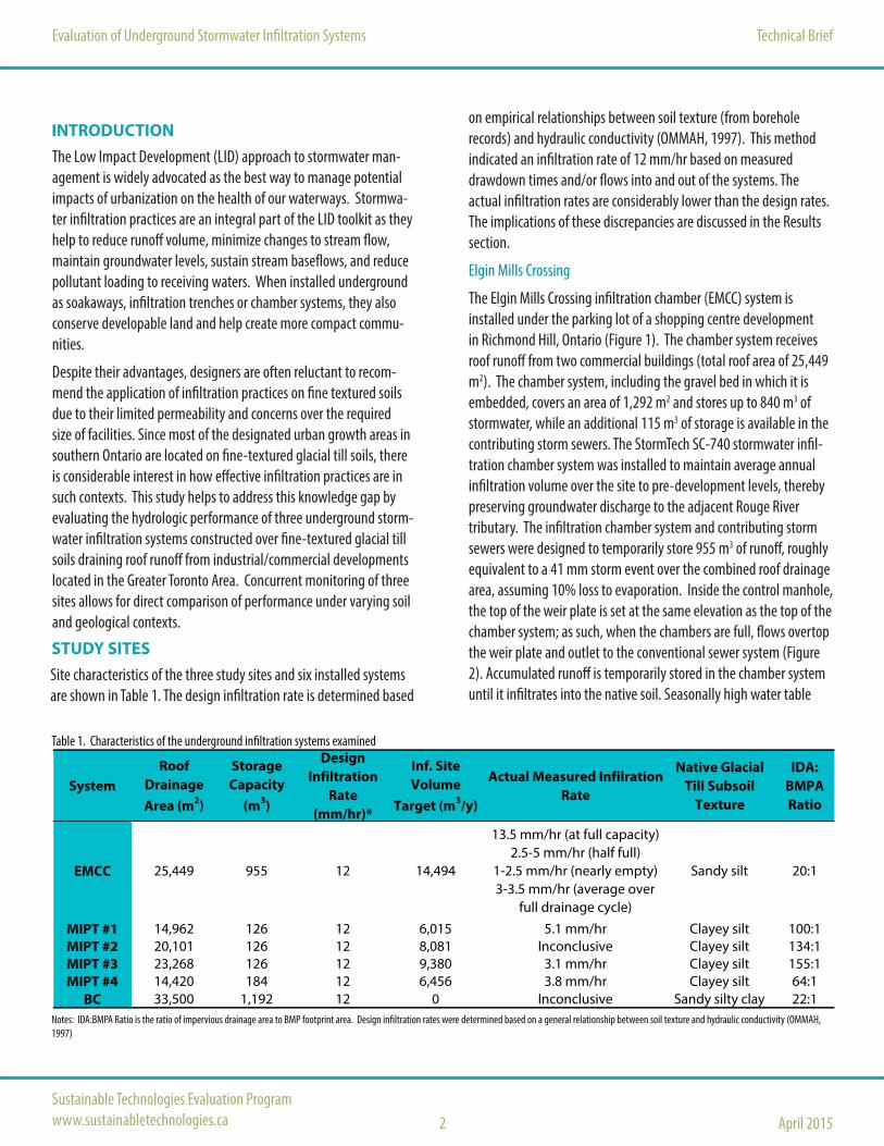
Table 1. Characteristics of the underground infiltration systems examined
Notes: IDA:BMPA Ratio is the ratio of impervious drainage area to BMP footprint area. Design infiltration rates were determined based on a general relationship between soil texture and hydraulic conductivity (OMMAH, 1997)
INTRODUCTIONThe Low Impact Development (LID) approach to stormwater man-agement is widely advocated as the best way to manage potential impacts of urbanization on the health of our waterways. Stormwa-ter infiltration practices are an integral part of the LID toolkit as they help to reduce runoff volume, minimize changes to stream flow, maintain groundwater levels, sustain stream baseflows, and reduce pollutant loading to receiving waters. When installed underground as soakaways, infiltration trenches or chamber systems, they also conserve developable land and help create more compact commu-nities.
Despite their advantages, designers are often reluctant to recom-mend the application of infiltration practices on fine textured soils due to their limited permeability and concerns over the required size of facilities. Since most of the designated urban growth areas in southern Ontario are located on fine-textured glacial till soils, there is considerable interest in how effective infiltration practices are in such contexts. This study helps to address this knowledge gap by evaluating the hydrologic performance of three underground storm-water infiltration systems constructed over fine-textured glacial till soils draining roof runoff from industrial/commercial developments located in the Greater Toronto Area. Concurrent monitoring of three sites allows for direct comparison of performance under varying soil and geological contexts.
EMCC 25,449 955 12 14,494
13.5 mm/hr (at full capacity) 2.5-5 mm/hr (half full)
1-2.5 mm/hr (nearly empty) 3-3.5 mm/hr (average over
full drainage cycle)
Sandy silt 20:1
MIPT #1 14,962 126 12 6,015 5.1 mm/hr Clayey silt 100:1MIPT #2 20,101 126 12 8,081 Inconclusive Clayey silt 134:1MIPT #3 23,268 126 12 9,380 3.1 mm/hr Clayey silt 155:1MIPT #4 14,420 184 12 6,456 3.8 mm/hr Clayey silt 64:1
BC 33,500 1,192 12 0 Inconclusive Sandy silty clay 22:1
SystemNative Glacial
Till Subsoil Texture
IDA: BMPA Ratio
Design Infiltration
Rate (mm/hr)*
Actual Measured Infilration Rate
Roof Drainage Area (m2)
Storage Capacity
(m3)
Inf. Site Volume
Target (m3/y)
Site characteristics of the three study sites and six installed systems are shown in Table 1. The design infiltration rate is determined based
on empirical relationships between soil texture (from borehole records) and hydraulic conductivity (OMMAH, 1997). This method indicated an infiltration rate of 12 mm/hr based on measured drawdown times and/or flows into and out of the systems. The actual infiltration rates are considerably lower than the design rates. The implications of these discrepancies are discussed in the Results section.
Elgin Mills Crossing
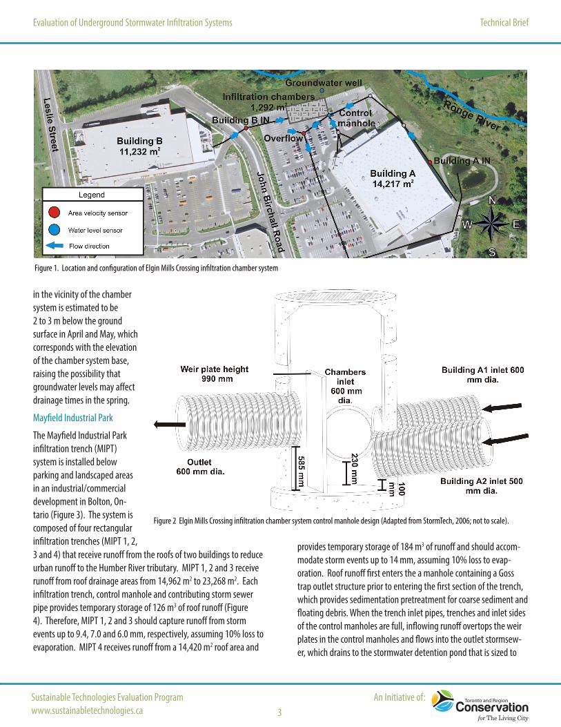
The Elgin Mills Crossing infiltration chamber (EMCC) system is installed under the parking lot of a shopping centre development in Richmond Hill, Ontario (Figure 1). The chamber system receives roof runoff from two commercial buildings (total roof area of 25,449 m2). The chamber system, including the gravel bed in which it is embedded, covers an area of 1,292 m2 and stores up to 840 m3 of stormwater, while an additional 115 m3 of storage is available in the contributing storm sewers. The StormTech SC-740 stormwater infil-tration chamber system was installed to maintain average annual infiltration volume over the site to pre-development levels, thereby preserving groundwater discharge to the adjacent Rouge River tributary. The infiltration chamber system and contributing storm sewers were designed to temporarily store 955 m3 of runoff, roughly equivalent to a 41 mm storm event over the combined roof drainage area, assuming 10% loss to evaporation. Inside the control manhole, the top of the weir plate is set at the same elevation as the top of the chamber system; as such, when the chambers are full, flows overtop the weir plate and outlet to the conventional sewer system (Figure 2). Accumulated runoff is temporarily stored in the chamber system until it infiltrates into the native soil. Seasonally high water table
Evaluation of Underground Stormwater Infiltration Systems Technical Brief
Sustainable Technologies Evaluation Programwww.sustainabletechnologies.ca
An Initiative of:3
Figure 2 Elgin Mills Crossing infiltration chamber system control manhole design (Adapted from StormTech, 2006; not to scale).
Figure 1. Location and configuration of Elgin Mills Crossing infiltration chamber system
in the vicinity of the chamber system is estimated to be 2 to 3 m below the ground surface in April and May, which corresponds with the elevation of the chamber system base, raising the possibility that groundwater levels may affect drainage times in the spring.
Mayfield Industrial Park
The Mayfield Industrial Park infiltration trench (MIPT) system is installed below parking and landscaped areas in an industrial/commercial development in Bolton, On-tario (Figure 3). The system is composed of four rectangular infiltration trenches (MIPT 1, 2, 3 and 4) that receive runoff from the roofs of two buildings to reduce urban runoff to the Humber River tributary. MIPT 1, 2 and 3 receive runoff from roof drainage areas from 14,962 m2 to 23,268 m2. Each infiltration trench, control manhole and contributing storm sewer pipe provides temporary storage of 126 m3 of roof runoff (Figure 4). Therefore, MIPT 1, 2 and 3 should capture runoff from storm events up to 9.4, 7.0 and 6.0 mm, respectively, assuming 10% loss to evaporation. MIPT 4 receives runoff from a 14,420 m2 roof area and
provides temporary storage of 184 m3 of runoff and should accom-modate storm events up to 14 mm, assuming 10% loss to evap-oration. Roof runoff first enters the a manhole containing a Goss trap outlet structure prior to entering the first section of the trench, which provides sedimentation pretreatment for coarse sediment and floating debris. When the trench inlet pipes, trenches and inlet sides of the control manholes are full, inflowing runoff overtops the weir plates in the control manholes and flows into the outlet stormsew-er, which drains to the stormwater detention pond that is sized to

Technical BriefEvaluation of Underground Stormwater Infiltration Systems
April 2015Sustainable Technologies Evaluation Programwww.sustainabletechnologies.ca 4
provide enhanced quality control. Seasonally high water table elevations in the vicinity of the trench system are estimated to be between 14 and 19 m below its base and will not affect drainage times.
Bramport
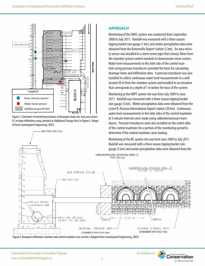
The Bramport infiltration chamber (BC) system is installed below a parking lot in a shopping centre development in Brampton, ON (Figure 5). The 1520 m2 CULTEC Recharger V8HD subsurface stormwater chamber system receives roof, road and parking lot runoff from a 33,500 m2 drainage area that drains to a warm water tributary of the Humber River. The system was designed to provide temporary storage and controlled release of runoff from storms up to the 100 year return period. A 833 m3, 0.3 m deep gravel bed with no outlet below a portion of the chamber area provides 100 m3 of water storage in addition to the 1192 m3 required to meet flood control requirements. It was included in the design to act like a permanent pool to provide better retention of sediment and the means to evaluate whether or not substantial infiltration occurs. Orifice flow restricting plates mounted on the outlets of each manhole cause stormwater to back up into the chambers and contributing storm sewers (Figure 6). When flow into the manhole exceeds the max-imum flow rate of the orifice plate, stormwater backs up into the chambers. Seasonally high water table elevations are between 2.5 and 4.6 m below the ground, which intersects with the system base, raising the possibility that groundwater levels may affect drainage times. As groundwater wells and nested peizometers were not installed on site, it is not possible to determine whether a perched water table is present that could nega-tively affect infiltration rates.
Figure 3. Mayfield Industrial Park infiltration trench system and configuration.
Figure 4. Mayfield Infiltration Trenches 1,2 and 3 control manhole cross-section (A.M. Candaras, 2007)
Evaluation of Underground Stormwater Infiltration Systems Technical Brief
Sustainable Technologies Evaluation Programwww.sustainabletechnologies.ca
An Initiative of:5
APPROACHMonitoring of the EMCC system was conducted from September 2008 to July 2011. Rainfall was measured with a three season tipping bucket rain gauge (1 km) and winter precipitation data were obtained from the Buttonville Airport station (5 km). An area veloci-ty sensor was installed in a storm sewer pipe that conveys flows from the chamber system control manhole to downstream storm sewers. Water level measurements in the inlet side of the control man-hole using pressure transducers provided the basis for calculating drainage times and infiltration rates. A pressure transducer was also installed to collect continuous water level measurements in a well located 20 m from the chamber system and installed to an elevation that corresponds to a depth of 1 m below the base of the system.
Monitoring at the MIPT system site was from July 2009 to June 2011. Rainfall was measured with a three season tipping bucket rain gauge (5 km). Winter precipitation data were obtained from the Lester B. Pearson International Airport station (20 km). Continuous water level measurements in the inlet sides of the control manholes at 5 minute intervals were made using calibrated pressure trans-ducers. Pressure transducers were also installed on the outlet sides of the control manholes for a portion of the monitoring period to determine if the control manholes were leaking.
Monitoring at the BC system site was from June 2009 to July 2011. Rainfall was measured with a three season tipping bucket rain gauge (5 km) and winter precipitation data were obtained from the
Figure 5. Schematic of monitoring locations at Bramport study site. Grey area shows 0.3 m deep infiltration sump, denoted as ‘Additional Storage Area’ in Figure 6. (Adapt-ed from Counterpoint Engineering, 2007).
Figure 6. Bramport infiltration chamber and control manhole cross-section ( Adapted from Counterpoint Engineering, 2007).

Technical BriefEvaluation of Underground Stormwater Infiltration Systems
April 2015Sustainable Technologies Evaluation Programwww.sustainabletechnologies.ca 6
Although the infiltration systems did not fully drain be-tween rain events , two of the three stormwater infiltration systems provided substantial reductions in runoff volume from their roof drainage areas. In the case of the EMCC system, even though the control manhole was observed to be leaking a small amount of water around the weir wall and the system drained slowly, the system reduced approximately 90% of runoff from the roof, slightly exceeding the pre-development infiltration volume over the developed site. Nearly all storm events under 15 mm in depth (or roughly 50% of the total rainfall depth over the study period) produced negligible outflow (Figure 7). Events greater than 15 mm depth began to produce outflow due in part to leakage in the control manhole and relatively slow infiltration, which reduced system storage capacity prior to storm events. The MIPT systems were not sized to provide full water balance control, but were still
FINDINGS
found to reduce runoff from their roof drainage areas by between 16 and 36% during a normal precipitation year.
Results from this study show that, if sized appropriately, the MIPT systems could have fully compensated for the loss of infiltration caused by the development through infiltration of roof runoff alone. This conclusion was derived from a spread-sheet model calibrated based on site measurements and run using precipitation inputs for a normal year. This model showed that in order to fully compensate for the volume of water lost due to the urbanization, the trenches would need to cover an area of between 2 and 5 times that of the current areas, assuming the trenches are all 2 m deep. This would represent a ratio of impervious drainage area to facility footprint of roughly 34:1 (see Table 1 for current ratios). With larger trench volumes, the average annual runoff reduction rates in a normal precipitation year would increase from 16% to 53% for MIPT 1 and 3, and from 36% to 61% for MIPT 4.
At all the sites examined, post-development infiltration rates of the subsoil were lower than expected based on de-sign assumptions. This resulted in slower than expected drainage of stored runoff and more frequent overflow occurrences. The EMCC and BC sites have seasonally high water tables that are close to the elevation of the chamber bases, which could have inhibited the hy-draulic gradient necessary for infiltration to occur. This suggests that infiltration practice designs should give more detailed consideration to the water table position and type of soils at the potential sites. Since the MIPT trenches never fully drained between storm events
0
25
50
75
100
0
10
20
30
40
50
0 10 20 30 40 50
% o
f Tot
al P
reci
pita
tion
Dep
th in
Eve
nts
≤ Ev
ent
Dep
th
Out
flow
vol
ume
(mm
)
Precipitation depth (mm)
Outflow (mm) % of TPD 1:1 Ratio
Some events> 15 mm produce
outflow but overall RR is
90%
Most events ≤ 15 mm produced no outflow
Outflow greater than inflow during rain-on-snow events
when the system was already filled to capacity
50% of TPD occurred as events ≤ 15 mm
Figure 7. Scatter plot of individual storm event precipitation depths and outflows for the EMCC over the full study period (TPD = Total Precipitation Depth).
Lester B. Pearson International Airport station (12 km). Calibrated pressure transducers were installed in two bottomless monitoring manholes that extend to the base of the system in order to estimate post-development infiltration rates in the undrained 30 cm deep gravel bed. An area velocity sensor was installed in the pipe con-necting the control manhole to the chamber system to provide an indication of when flow from the system into the control manhole had ceased, confirming that subsequent water level declines in the monitoring manholes reflect losses to infiltration only.
and the control manholes contained standing water for much of the year, they could have provided a mosquito breeding habitat. Standing water in control manholes was sampled on three occasions over the study period and no mosquito larvae were found.
In both the EMCC and MIPT systems it was ob-served that infiltration rates decreased exponen-tially as water levels declined. The trenches did not exhibit significant seasonal variation in infiltration rates due to their depth which insulates them from surface air temperature fluctuations. Thus, the trenches perform more efficiently when the water level is high, demonstrating a benefit of maintaining a certain level of hydraulic head in the system at all times (Figure 8). Con-versely, drainage rates are very slow (≤ 1 mm/h ) when trench water levels are 1 m in depth or less, suggesting that infiltration practices with shallow reservoirs will not

Evaluation of Underground Stormwater Infiltration Systems Technical Brief
Sustainable Technologies Evaluation Programwww.sustainabletechnologies.ca
An Initiative of:7
Figure 8. Mayfield Trench #3 drainage time during an August 2009 storm event.
0
1
2
3
4
5
0
500
1000
1500
2000
2500
3000
3500
28/08/2009 02/09/2009 07/09/2009 12/09/2009 17/09/2009 22/09/2009
Rain
(mm
/hou
r)
Wat
er L
evel
(mm
)
Overflow Elevation
Top of Infiltration Trench
22.8 Days
2.5-3.8 mm/hour | 2 Days
1.5-2.5 mm/hour | 4.5 Days
1-1.5 mm/hour | 16.3 Days
drain well on fine-grained soils. It was observed for the BC site that the undrained 30 cm deep gravel bed reservoir does not substantial-ly infiltrate between storm events. This is consistent with the trend in drainage rates observed at the MIPT site which would predict very slow infiltration at trench water levels of 30 cm depth or less, assum-ing subsoils at the two sites have similar drainage characteristics.
The unique design of the BC system made it difficult to determine with confidence the extent to which negligible water level drawdown rates were due to low permeability soils or other factors. A number of factors confounded interpre-tation of infiltration results at this site. First, the infiltration sump was shallow (only 30 cm), which as mentioned above, can result in relatively slow infiltration on low permeability soils (Figure 8). Pre-development geotechnical surveys also showed a seasonally
Figure 9. Capital and Net Present Value (NPV) over a 50 year evaluation period for treatment of asphalt runoff by OGS and infiltration chambers with two types of pretreatment (gravel filter and OGS). Left graph shows cost per m2 of paved drainage area and right graph shows cost per kilogram of annual TSS load reduced. Assumes 90% runoff reduction for infiltration chambers (this study) and 50% TSS removal for all treatment practices.
high groundwater table that may have further reduced drainage. Other factors may relate to how the system was designed and constructed. A horizontal pipe that acts as both the inlet and outlet of the system connects to the base of the chambers. If the gravel bed below the chambers was not completely level with the outlet pipe, wa-ter may drain through the gravel bed slowly into the infiltration sump after rain events. This would cause the sump to empty and fill at the same time, giving the impression that water is not infiltrating. Saturated conditions in the native soils below the chambers may also reduce infiltration through the sides, creating a unique situation not experienced in most other trench or chamber systems designed
solely for infiltration. Taken together, these factors prevent meaning-ful interpretation of the water level drawdown data at this site.
Based on contributing drainage area, underground infiltra-tion systems are on average cheaper to maintain than a con-ventional asphalt pavement and oil and grit separator (OGS). When treating road runoff, underground infiltration practices with simple pre-treatment can have lower life cycle costs than conven-tional treatment practices. The cost analysis presented in Figure 9 is based on a separate STEP study on the life cycle costs of LID practices (Uda et al., 2013). Calculations assume a road drainage area of 2000 m2 for each practice. While oil grit separator (OGS) capital costs are lower than the infiltration chambers, life cycle costs for infiltration chambers with pre-treatment through a gravel inlet are less than for conventional OGS. This is because underground infiltration systems
and gravel inlets are considered to be relatively inexpensive to maintain. Un-like conventional treatment practices, underground infiltration systems also provide significant runoff reductions. Therefore when costs are expressed per unit of suspended solids load reduced, the infiltration chambers are shown to be the most cost effective options (Figure 9). Comparing trenches with chambers, the chambers were found to be at least 7% less expensive to con-struct than trenches because chambers make more efficient use of space for water storage.

Evaluation of Underground Stormwater Infiltration Systems Technical Brief
April 2015Sustainable Technologies Evaluation Programwww.sustainabletechnologies.ca
This communication has been prepared by the Toronto and Region Conservation Authority’s Sustainable Technologies Evaluation Program. Funding support for this study was provided by Region of Peel, Region of York, City of Toronto, Government of Canada’s Great Lakes Sustainability Fund, RioCan Developments, Sardo Foods, SmartCentres, Trinity Developments, and Toronto and Region Remedial Action Plan. The contents of this report do not necessarily represent the policies of the supporting agencies.
For more information on STEP’s other Low Impact Development initiatives, or to access the full report for this study, entitled Evaluation of Underground Stormwater Infiltration Systems, visit us online at www.sustainabletechnologies.ca
8
• In locations with fine textured subsoil and seasonally high water table or bedrock at least 3.5 m below ground surface, design criteria for systems servicing industrial, commercial and institutional devel-opments, where roof area is 50% or greater of the lot area, should include maintaining average annual pre-development infiltration volume over the lot through infiltration of roof runoff.• Since infiltration rates observed when the systems were full or nearly full were approximately 2.5 times higher than when the systems were half full or less, stormwater infiltration practices on fine-textured soil should be designed to maintain hydraulic head in the water storage reservoirs for longer than the typical target of 48 to 72 hours. This would help maximize the drainage rate and thereby, the volume of water infiltrated on an annual basis. On low permeability, clayey silt soils like those occurring at the MIPT site, this means designing infiltration systems that never fully drain between storm events.• To maintain average annual pre-development infiltration volume over the lot on fine textured glacial till soils it is recommended that gravel-filled water storage reservoirs should be at least 2 m in depth and sized to provide a minimum Impervious Drainage Area : BMP Footprint Area Ratio (IDA:BMPA Ratio) of 30:1.
CONCLUSIONS AND RECOMMENDATIONS
REFERENCESA.M. Candaras Associates. 2007. Lot 1, Pillsworth Dr. Industrial Building ‘A’, Town of Caledon, Region of Peel – Site Servicing, Grading and Stormwater Management Drawing No. G1. Project No. 0730. Revised August 1, 2007. Woodbridge, ON. Counterpoint Engineering. 2007. Bramport Commercial Development, City of Brampton, Airport Road and Bovaird Drive – Site Servicing Plan Drawing No. SW-S1. Project No. 04160. May 7, 2007. Vaughan, ON. Ontario Ministry of Municipal Affairs and Housing (OMMAH). 1997. Supplementary Guidelines to the Ontario Building Code 1997. SG-6 Percolation Time and Soil Descriptions. Toronto, Ontario.StormTech. 2006. Trinity / MH36 Detail (drawing). November 29, 2006. Wethersfield, CT. Uda M, Van Seters T, Graham C, Rocha L (2013) Evaluation of Life Cycle Costs for Low Impact Development Stormwater Management Practices. Sustainable Technologies Evaluation Program, Toronto and Region Conservation Authority. Young D, Van Seters T, Graham C (2013) Evaluation of Underground Stormwater Infiltration Systems. TRCA’s Sustainable Technologies Evaluation Program, Toronto.
• Detailed design of infiltration practices should be based on field measurements of subsoil hydraulic conductivity or percolation rate at the depth corresponding to the base of the BMP, and not rely on estimates based on soil texture classification. • Stormwater infiltration facilities should be thoroughly inspected during and immediately after construction and any deficiencies should be corrected prior to acceptance. Inspection procedures should include continuous water level monitoring over several storm events or a synthetic runoff test to ensure the system is functioning as expected. • Leakage of water from the inlet side to the outlet side of the control manholes was observed in 2 of the 5 facilities indicating that sealing of the joints between components used to construct the manholes needs to be improved or given more attention during construction.• In the control manholes, including an outlet with a valve through the weir wall that can be operated from the outlet side would better facilitate inspection and maintenance by allowing the system to be drained via gravity.• Incorporating sumps in the control manholes would help prevent clogging of the bottom perforated pipes from sediment accumula-tion, which was observed for 3 of the 5 facilities, although it did not influence their hydrologic performance.