evaluation of explosives using ground vibration criterion...
TRANSCRIPT

EVALUATION OF EXPLOSIVES USING GROUND
VIBRATION CRITERION A THESIS SUBMITTED IN PARTIAL FULFILLMENT OF THE
REQUIRMENTS FOR THE DEGREE OF
BACHELOR OF TECHNOLOGY
IN
MINING ENGINEERING
BY
SANJIB KUMAR PRDHAN
And
ASHRIT DAS
DEPARTMENT OF MINING ENGINEERING NATIONAL INSTITUTE OF TECHNOLOGY
ROURKELA, ORISSA - 769008 2007
EVALUATION OF EXPLOSIVES USING GROUND
VIBRATION CRITERION A THESIS SUBMITTED IN PARTIAL FULFILLMENT OF THE
REQUIRMENTS FOR THE DEGREE OF
BACHELOR OF TECHNOLOGY IN
MINING ENGINEERING BY
SANJIB KUMAR PRDHAN And
ASHRIT DAS
UNDER GUIDANCE OF Dr. MANOJ KU. MISHRA
DEPARTMENT OF MINING ENGINEERING NATIONAL INSTITUTE OF TECHNOLOGY
ROURKELA, ORISSA - 769008 2007

NATIONAL INSTITUTE OF TECHNOLOGY ROURKELA
CERTIFICATE
This is to certify that the thesis entitled, “Evaluation of Explosives using ground vibration
criterion” submitted by Sri Ashrit Das and Sri Sanjib Kumar Pradhan in partial
fulfillment of the requirements for the award of Bachelor of Technology Degree in
Mining Engineering at the National Institute of Technology, Rourkela (Deemed
University) is an authentic work carried out by him under my supervision and guidance.
To the best of my knowledge, the matter embodied in the thesis has not been submitted to
any other University/ Institute for the award of any Degree or Diploma.
Date:
Dr. Manoj Kumar Mishra
Dept. of Mining Engineering
National Institute of Technology
Rourkela, 769008

ACKNOWLEDGEMENT I wish to express my deep sense of gratitude and indebtedness to Dr. Manoj Kumar
Mishra, Department of Mining Engineering, N.I.T Rourkela for introducing the present
topic and for his inspiring guidance, constructive criticism and valuable suggestion
throughout this project work.
I would like to express my gratitude to Prof. B.K.Pal (Head of the Department), for
his valuable suggestions and encouragements at various stages of the work.
I am also thankful to all staff members of Department of Mining Engineering
NIT Rourkela. I am grateful to Mr. N.B.Samal Blasting incharge of Bharatpur
opencast mines, MCL, Talcher for helping us for doing measurements in their mine.
I am also thankful to Mr. P.N.Mallick and other staffs in Department of Mining
Engineering for providing all joyful environments in the lab and helping me out in
different ways.
Last but not least, my sincere thanks to all my friends who have patiently
extended all sorts of help for accomplishing this undertaking.
Date: Sanjib Kumar Pradhan
Ashrit Das

CONTENTS Page no:
Abstract i-ii
List of Tables iii
List of Figures iv
Chapter 1 Introduction 1-4
1.1 Background 1.2 Research Questions 1.3 Goal 1.4 Objectives
Chapter 2 Literature Review 5-40
2.1 Blast Vibration
2.1.1 Historical perspective
2.1.2 What is Blast Vibration?
2.1.3 Parameters influencing blast vibration
2.1.4 Theory of Blast Vibration
2.1.5 Factors Taken into Account during Ground Vibration
2.1.5.1 Natural Frequencies
2.1.5.2 Structural response
2.2 Shock wave propagation causing vibration
2.2.1 Properties of blasting waves
2.2.2 Types of vibration
2.2.3 Types of Waves Generated by the Blast
2.2.4 Vibration Waves
2.3 Peak particle velocity
2.3.1 Factors affecting particle velocity
2.3.2 Blasting – Limiting Vibration – Methodology

2.3.2.1 Scaled Distance
2.3.2.2 Square Root Scaling
2.3.2.3 Cube Root Scaling
2.4 Blasting damage
2.5 Standards regarding ground vibration
2.6 Control ground vibrations
2.6.1 Combination inter hole and inter row delays
2.6.2 Prediction and modeling of blast-induced vibrations
2.6.3 Minimization of blast-induced ground vibrations
2.6.4 Presplitting Rock Excavation Slopes
2.6.5 Minimization of blast-induced structural vibrations
Chapter 3 Data collection 41-52
3.1 Introduction
3.2 Description of Quarry Site
3.3 Surrounding Structures
3.4 Data Collection
3.5 Instrument used for Vibration Monitoring
3.6 Data analysis
Chapter 4 Recommendations and Conclusion 53-56
4.1 Recommendations
4.2 Conclusion
REFERENCES 57-58

ABSTRACT Recent times have experienced an increase in infrastructure and mineral resource
developments. As a result, mining activities have also increased to supply the needed
mineral. Blasting has been the main technique for loosening insitu rock before use.
Consequently there is a growing concern of the effects of blasting activities on the
environment. These effects are normally nuisances to the neighboring residence as they
come in the form of: dust, toxic gases, noise, fly rocks and ground vibration. Of the set of
nuisances the one that is of most concern is ground vibrations which can cause damage to
structures. In most cases worldwide, after blasting activities there are the usual
complaints about damage to residence, and less mining activities which is also a focus of
the thesis. A study was conducted to evaluate the effect of heavy blasting in open-pit coal
mines on the stability of adjoining under ground coal mine workings. There have been researches on the subject of ground vibrations to help refute
some of these complaints. The works of Lewis Oriard and Charles Dowding are the
foundation on which standards and regulations are built as guides to assist blasters in the
prevention of creating unnecessary nuisances. Most countries have developed their own
regulations with respect to blasting and parameters are set according to the geological
conditions. This is of importance as the rock structures determine the transmission of the
peak particle velocity. However, most countries in the west adopt standards similar to
ones put forward by the United States Bureau of Mines. It my opinion that a whole scale
adoption should not take place as the criteria used may not be suitable for other countries’
geological conditions.
For this thesis the aim was to identify a vibration level that will not cause damage
to structures close to a mining area and increase production by effective blasting. Based
on the literature review it was revealed that there are a number of parameters that needed
to be considered. These ranges: construction material, age of structures, distance from
structures, geology of the location, type and quantities of explosives and the blast design.
There was also the review of standards to building threshold with respect to the level of
ground vibration.
i

The case study with its main focus on evaluation of explosive using ground vibration
criterion which will not result in any form of damage to the structures. However, having
established a PPV limit using the USBM that appears reasonable there is the need for
criteria similar to those of the USBM using blasting and geological conditions.
ii

LIST OF TABLES
Table 1: Different types of vibration
Table 2: Typical P and S wave velocity in rocks
Table 3: Permissible peak particle velocity
Table 4: Limiting blasting vibration criterion
Table 5: Threshold value of vibration for safety of underground workings
Table 6: Effects of ground vibration on human beings
Table 7: Ground vibration limits
Table 9: Classification of blasting damage
iii

LIST OF FIGURES
Figure 1: Different modes of release of energy from blasting
Figure 2: Record of typical blasting vibration
Figure 3: Orthogonal axes for assessment of human exposure to vibration
Figure 4: Vibration waves from a cratering charge
Figure 5: Threshold values of peak particle velocity at different RMR of roof rock.
Figure 6: Different damage zones based on PPV and RMR
Figure 7: Distribution of blasting related injuries in the mining industry
Figure 8: Principle of superposition of blast vibration waveform
Figure 9: Bench blast design with delay
Figure 10: Position of Bharatpur opencast mine, MCL
Figure 11: Site 1
Figure 12: Site 2
Figure 13: Site 3
iv

1
CHAPTER: 1
Introduction
Back Ground
Research Questions
Goal
Objectives

2
CHAPTER 1 1 Introduction 1.1 Background Blasting is perhaps one of the most interesting, thought provoking, challenging
& controversial areas of the mining industry. It encompasses many areas in the science of
chemistry, physics, thermodynamics, shock wave interaction & rock mechanisms. In
broad terms rock breakage by explosive involves the action of an explosive & response of
the surrounding rock mass. Past, current & new blasting theories are presented along with
the factors affecting fragmentation & general blast design criteria by many research
people.
The vibrations radiating from the blast holes while passing through surface
structures induce vibrations on the structures causing resonance. The components of
ground motion can affect the structures through compression and tension and also
through vertical and horizontal shearing effects. Blast induced ground vibrations create
socioeconomic problems for the mine managements as well as the people residing in
vicinity of these mines. As only 20-30 % of energy of commercial explosives used in the
mines is utilized for fragmenting the rock, the rest of energy is transmitted through the
earth in the form of ground vibrations resulting in damage to the surrounding structures.
The concept of energy balance in rock blasting research has remained a
challenging field in the area of rock breakage using commercial explosives.
Unfortunately no single piece of work is available in India and abroad which could give a
thorough concept of energy partitioning and its effectiveness for proper, scientific and
cost effective blasting operation. Knowing well the limitations, the challenge was
accepted with a view to obtaining some basic understanding of the process of rock
breakage, efficacy of explosive energy and its utilization in the process of rock blasting.

3
In order to understand ground vibration and their associated problems, a review
of elastic theory, seismic wave propagation, geometrical scaling, vibration terminology
and development of damage criteria is essential.
1.2 Research Question However, irrespective of the reason and purpose the blasting activities usually
generate some level of annoyance to residents in the nearby population and possibilities
of damage to the structures in the proximity. The annoyance from blasting stem from
unused energy that was not sufficient to fracture the in-situ material further and lead to
these unfavorable activities. These would include, noise, fumes, fly rocks, air and ground
vibrations. These annoyances and nuisances usually result in the many complaints from
the populates in the neighboring areas. Despite the efforts of the competent blaster to
undergo the necessary precautions and design to ensure that the level of vibrations is
within the international as stipulated by USBM there will still be complaints. Since the
vibration levels obtained in most of the activities are within the stated thresholds and
complaints are increasing, this therefore prompts the questions for this research.
Ø Can the parameters be determined for ground vibrations and air over pressure for
maximum allowable PPV and tolerable noise level?
Ø What will this parameter be with respect to the USBM international standards?
1.3 Goal
The goal of this project is to evaluate explosives used in different mining operations
using ground vibration as a criterion. Based on the knowledge of the characteristics and
effect of blast vibration we select the type and the amount of explosive to be used in the
manner in which they have to be used for optimum result.
1.4 Objectives
The objectives of this project are as follows:
1. To identify the factors affecting blast vibration with the help of literature review.

4
2. To identify the relation of each factor with blast vibration with the existing
literature.
3. To develop a questionnaire for collection of data.
4. To collect blast vibration related data based on the questionnaire.
5. To investigate into the influence of blasting pattern and geotechnical properties of
the rock mass on the ground vibration.
6. To know the effects of blast vibration.
7. To identify the remedial measures to reduce or mitigate the negative impacts of
blast vibration.
5
CHAPTER: 2
Literature Review
Blast vibration
Shock wave propagation causing vibration
Peak particle velocity
Blasting damage
Standards regarding ground vibration
Control ground vibrations

6
CHAPTER 2
Literature Review
It includes the following
i. Study of theory behind blast vibration.
ii. Study of shock wave propagation causing vibration
iii. Study of peak particle velocity concept.
iv. Study of different damage criterion.
v. Consideration of various standards regarding ground vibrations.
vi. Techniques to control ground vibrations etc.
2.1 Blast vibration.
2.1.1 Historical perspective
By far the most common technique of rock excavation is that of drilling
and blasting. From the earliest days of blasting with black powder, there have been steady
developments in explosives, detonating and delaying techniques and in our understanding
of the mechanics of rock breakage by explosives. It is not the development in blasting
technology that is of interest in this discussion. It is the application of this technology to
the creation of excavations in rock and the influence of the excavation techniques upon
the stability of the remaining rock.
As is frequently the case in engineering, subjects that develop as separate
disciplines tend to develop in isolation. Hence, a handful of highly skilled and dedicated
researchers, frequently working in association with explosives manufacturers, have
developed techniques for producing optimum fragmentation and minimizing damage in
blasts

7
2.1.2 What is Blast Vibration?
It can be defined as the shaking of the ground caused by the elastic wave
emanating from a blast and consisting of innumerable individual particles. These particles
are either body waves or surface waves. Body waves when reflected or refracted to the
surface, become surface waves. Ground motion consists of a combination of these waves.
These waves affect buildings and structures on the surface and around the vicinity of the
excavation through compression and tension and through vertical and horizontal shearing
effects.
2.1.3 Parameters influencing blast vibration
The level of ground and structure vibration caused by blasting depends on explosive type
and weight, delay timing vibration, blasting technology, site geology, scale distance,
parameters of waves propagating at site, susceptibility ratings of adjacent and remote
structures and other factors.
Burden: It is the minimum distance between face and blast hole. Too less burden can
cause fly rock and air blast problem and too high a burden will produce sever back break
and greater vibration. Burden should be 0.5 to 0.8 times of the height of bench.
Spacing: It is the distance between two consecutive blast hole.
Spacing = (1.2 to 1.5) burden
Stemming: It is used after explosive is loaded in blast holes. Stemming affects blown out
shot of the hole and also affects fly rocks.
Stemming/burden > 0.6 (for controlling fly rock)
Bore hole depth: It not only affects fragmentation but also the level of vibration. Bore
hole depth is a function of spacing and diameter of the hole. Short holes produce blasting
at greater violence and also produce greater vibration level of increased frequency.

8
Sub drilling: It is generally used for eliminating toe formation of the bench. About 10%
of sub drilling gives better fragmentation in the rock mass and lesser ground vibration.
Geology of the area: The propagation of energy through vibration waves depends upon
the elastic properties of the medium. The rock types of the area and structured features
play a great part in propagation of energy.
Types of explosives: Ground vibration is directly proportional to the type of explosives
used.
Explosive quantity: The level of vibration produced by a single row instantaneous blast
is same as the level of vibration produced by a single or multi row blast with delay if the
charge quantity per delay of the blast with delay equals to the total charge of the single
row blast. Thus it is the charge per delay that controls the level of blasting not the total
charge.
2.1.4 Theory of Blast Vibration
There is always ground vibration due to the blasting operation. The energy not utilized in
the breakage process is wasted energy. This energy is dissipated in the form of vibration
air blast and water shock. Vibration is wave motion created from an energy source, in the
case of rock blasting; the source is explosive energy and rock movement. The damaging
potential of vibration caused by blasting is related with maximum velocity of vibration of
the blasted particles. When the vibration is transmitted through ground is called
propagation. The propagation velocity is the speed at which the vibration waves travel.
Energy balance
It is useful to view the blasting process as an ‘Energy Balance’ as shown in the
diagram below. Essentially, the chemical energy of the explosives must be dissipated as
fragmentation, rock movement, vibration and air overpressure. Very few percentage of an
explosive is being utilized for breakage of rock mass i.e, about 15 to 20% depending

9
upon the blasting technique. Rest of the maximum energy of the explosive is waste as
vibration and air overpressure i.e. around 40% in each case.
From figure:-1 it can be seen that a blast with poor fragmentation is likely to
have a higher than expected environmental impact.
Figure 1: Different modes of release of energy from blasting
As the disturbance passes a given point an individual particle of the medium is
displaced from its rest position. It is possible to record or measure this particle
displacement; alternatively, one may record the particle velocity or acceleration. Though
the three quantities are related, it is not a simple matter to deduce one from another
because the wave is not a simple one. It is desirable therefore to measure the quantity that
is most simply and generally related to damage.
2.1.5 Factors Taken into Account during Ground Vibration
Three factors of ground vibrations determine how much effect it has: ground
vibration amplitude (PPV), ground vibration duration, which is not the same as blast
duration and Ground vibration frequency.
Duration is important because the longer ground vibrations continue to shake
the structure, the greater the amplitude of the structural response. In addition, studies
have shown that human tolerance to vibration decreases the longer the vibration
continues. Seismographs report PPV and frequency, but duration often is ignored.

10
Frequency is the most important of the three factors of ground vibration. When
a structure is exposed to ground vibrations near its fundamental frequency, the structure
magnifies the vibrations. Besides these, two more things to be taken into consideration
are
2.1.5.1 Natural Frequencies
Elements of building construction such as sprung floors, stud partition walls,
ceiling and windows can all react as mass-spring systems; each with its own natural
frequencies of about 4-24 Hz (low frequencies) Ground vibrations at these frequencies
amplified by the structures increase the risk of damage. When the low frequency ground
vibration coincides with the natural frequency of the structure resonance in originated.
The resonance is a state in which the structure absorbs most energy progressively
becoming deformed with time, until plastic deformation occurs. Therefore even the low
peak particle velocity of ground vibrations at natural frequency of structure is more
harmful to the structure. Natural frequencies of brick and concrete structure generally
vary from 8- 16 Hz.
2.1.5.2 Structural response
Structural response is directly and linearly proportional to ground vibration amplitude.
The cracking location and the wall material have an influence on the particle velocity at
which cracking begins. If the entire structure is not inspected thoroughly, there may be
chances of biased opinion on the type of cracks. Thus it is important to place transducer
properly for the correct assessment of damage.
In the mud houses, numbers of cracks develop before blasting and these cracks
widened and extended with the passage of time. These cracks are further widened and get
extended due to blast induced ground vibrations. Concrete structures vibrate for longer
duration that brick and mud structures. Concrete walls have free top and show no cracks
at vibration levels for which mud and brick walls can damage Cracks develop in concrete
walls with large vibration level. Cracks in brick- structures can be observed in junction of

11
walls, roof and at window corners. Brick walls with clay mortar and cement- sand mortar
behave in same fashion. Steel structures can sustain more vibration level.
The magnitude of vibration on structures is much more than on the ground.
Duration of vibration in structure is also longer than, that of ground vibration. Multi-
storied buildings are more sensitive to blast vibration that the single-storied buildings.
2.2 Shock wave propagation causing vibration
2.2.1 Properties of blasting waves
At the immediate site of an explosion the disturbance takes the form of a
single pulse, whose peak amplitude and duration depend on the properties of the medium
and the properties and size of the explosive charge. The resulting elastic wave usually has
a strong initial build-up, followed by an irregular series of oscillations.
Figure 2. Record of typical blasting vibration
2.2.2 Types of vibration
Vibration in buildings can be caused by many different external sources, including
industrial, construction and transportation activities. The vibration may be continuous
(with magnitudes varying or remaining constant with time), impulsive (such as in shocks)
or intermittent (with the magnitude of each event being either constant or varying with
time). Examples of typical types of vibration .Vibration in buildings may also occur from

12
internal sources (within a building structure),such as a road development forming part of
the building structure, or mechanical vibration sources in buildings. Vibration and its
associated effects are usually classified as continuous, impulsive or intermittent as
follows:
Continuous vibration continues uninterrupted for a defined period (usually throughout
Day time and/or night-time). This type of vibration is assessed on the basis of weighted
rms acceleration values.
Impulsive vibration is a rapid build up to a peak followed by a damped decay that may
or may not involve several cycles of vibration (depending on frequency and damping). It
can also consist of a sudden application of several cycles at approximately the same
amplitude, providing that the duration is short, typically less than 2 seconds.
Intermittent vibration can be defined as interrupted periods of continuous (e.g. a drill)
or repeated periods of impulsive vibration (e.g. a pile driver), or continuous vibration that
varies significantly in magnitude. It may originate from impulse sources (e.g. pile drivers
and forging presses) or repetitive sources (e.g. pavement breakers), or sources which
operate intermittently, but which would produce continuous vibration if operated
continuously (for example, intermittent machinery, railway trains and traffic passing by).

13
Figure 3: Orthogonal axes for assessment of human exposure to vibration
Table 1: Different Types of vibration
Continuous Vibration Impulsive Vibration Intermittent Vibration
Machinery, steady road traffic, continuous construction activity (such as tunnel boring machinery)
Infrequent activities that create up to 3 distinct events in an assessment period (occasional dropping of heave material, occasional loading and unloading)
Trains, nearby intermittent construction activity, passing of heavy vehicles, forging machines, impact pile driving, jack hammers. Where the number of vibration events in an assessment period is three or fewer this would be assessed against vibration criteria.
2.2.3 Types of Waves Generated by the Blast
When an explosive is detonated in borehole, energy is transferred into the surrounding
rock as a result of the generated shock and gas pressures. Initially the pressure of the
shock wave is higher that the compressive strength of the rock and the rock around the

14
borehole is crushed. However the shock pressure decays quickly to values below the
compressive strength. At this point the shock travels inside the rock without breaking it in
compression.
Failure of the rock is a result of tension through the tensile component of the shock wave
or when the tensile wave is reflected as a tensile wave at media boundaries. With further
distance the shock waves attenuates into an elastic wave. In this case the stresses cause
the particles of the rock to oscillate about their rest positions as a spring-mass system.
There is no bulk movement or transport of matter during the wave motion.
The initial shock front applies a force to the rock in such a way as to compress it and
reduce its volume causing a wave similar to a sound wave. Its characteristic is that it
compresses and expands the rock by particle vibration in the direction of propagation.
There are two types of wave
1. Body wave
2. Surface wave
Body wave:
P wave (Compression and Tension Waves): This wave type is termed compress ional,
dilatational, longitudinal or Primary and is usually designated by the letter P (P-wave).
S wave: Another type of wave which is produced by the initial pressure pulse and the
later P wave interacting with discontinuities in the rock is the S-wave. This type of wave
is caused when the medium particles oscillate perpendicular to the propagation direction.
Sometimes it is referred to as shear, transverse or secondary.
Surface wave:
Introduction of one or more boundaries across which there are differences in elastic
properties can cause the introduction of other types of waves. The most significant
boundary is the surface of the earth. Two basic surface waves exist. These waves are
guided by the surface and are characterized by an exponential decrease in particle
oscillation amplitude with increasing distance from the boundary and by the propagation
of the wave from along the boundary. The two fundamental types of surface waves are
the Raleigh waves and the Love waves.

15
Raleigh wave: The Raleigh wave causes surface particles to describe an elliptical counter
clockwise orbit. These waves exist in the vertical radial plane and have no transverse
component.
Q wave: The Love wave (Q-wave) is characterized by particle vibration of the shear type
and only in the horizontal transverse direction. These waves are confined to a shallow
surface zone.
Figure 4: Vibration waves from a cratering charge (Bauer 1981)
Figure shows the main wave types associated with blasting. These are produced by a
hypothetical cratering charge. The P-waves are moving faster than the S-waves which are
moving faster than the surface waves. The table (4.3.1) shows velocities of P and S waves
in different rocks.

16
Table2: Typical P and S wave Velocities of Rocks
Material P Velocity, m/s S Velocity, m/s
Granite 4000-6000 2000-3000
Basalt 5500 3000
Sandstone 2000-3500 1000-2500
Limestone 3000-6000 2000-3000
Schist 4000-5000 2500-3000
Soil 150-1000 100-700
In general the S wave travels at a velocity of ½ to 1/3 of that of the P wave and
the Raleigh wave at a velocity of 0.9 to 0.95 of that of the S wave
(Oriard1996),(Bauer1981). At small distances all these waves arrive simultaneously
while at greater distances they separate and identification is possible. However in mining
most blasts consists of a series of explosions which are delayed by millisecond delays.
This results in overlapping of the waves. To describe the motions completely, three
perpendicular components are necessary. The longitudinal which has the direction of a
horizontal radius to the blast, the transverse which is perpendicular to the longitudinal on
the horizontal plane and the vertical, which is perpendicular to both the longitudinal and
the transverse.
2.2.4 Vibration Waves
To understand vibration control in tight blasting, the explosives engineer must understand
vibration wave construction and phenomenon.
Blast induced vibration waves can be divided into three main categories: compressive,
shear, and surface. To measure the motions, three perpendicular components of vibration
motion must be measured. They are as follows:

17
Ground vibration direction
1. Transverse- horizontal motion at right angles to the blast.
2. Vertical – Up and down movement
3. Longitudinal (Radial) - Horizontal movement along a line between the
recorder and the blast.
The main vibration wave types can be divided into body waves and surface waves.
Body wave: Body waves propagate through the body of the rock or soil.
P wave (Compression and Tension Waves): One type of body wave is known as P-
Waves. P-Waves are Push/Pull waves and they are the compression/dilatation in the
direction of wave travel. They travel in the following mediums: solids, liquid, gas. The
compression creates a change in volume of the medium. An example of these types of
waves occurs when a rope or string is stretched and vibrates.
S-Wave: The other type of body wave is the S-Wave. This is a transverse wave that
moves at right angles to the direction of wave travel. These waves can only travel in a
solid medium. S-Waves create a change in shape of the medium. An example would the
flexing a rope. The rope moves up and down, but the wave travels to the other end.
Surface wave: Surface Waves travel along the outer surface layer of rock. They do not
penetrate into the rock mass. The wave motion of surface waves decreases with depth. 1
wavelength in depth is equal to zero motion or no surface wave. Surface waves are larger
than body waves but travel slower (Frequency). These are the waves, which cause most
of the vibration problems and complaints. These waves are the large energy carriers and
produce the largest motions. There are two basic types of surface waves, the Love Wave
and the Rayleigh Wave.
Love Wave: Love Waves are transverse waves that propagate in a surface layer on top of
another medium (Soil overlying rock). Rayleigh waves travel in the free surface and the
particle motion is elliptical.
Rayleigh Wave: The Rayleigh wave causes surface particles to describe an elliptical
counter clockwise orbit. These waves exist in the vertical radial plane and have no
transverse component. Rayleigh waves travel in the free surface and the particle motion is
elliptical.

18
When blasting in the extreme near field (under 20 feet) without a soil layer,
these surface waves are almost non-existent. For the development of regulations, the
studies and research performed mostly involved the measurement of surface waves at
large distances. In tight blasting situations, the body waves are the dominant waves and
create surface waves when interacting with structures. Normally when body waves
interact with a free surface, the peak particle velocity is doubled.
2.3 Peak particle velocity
As the seismic waves travel through the rock, there are movements of the particles.
This is commonly referred to as vibration. The motion of the ground particles (vibration)
occurs in three dimensions which are vertical, radial and transverse. When there is
vibration each particle has a velocity and the maximum velocity is referred to as the peak
particle velocity. This motion is usually captured by the use of a seismograph and the
maximum velocities of all three directions are given. The practice by most is to use the
reading of the peak particle velocity as the standard for measuring the intensity of the
ground vibration. In reporting, the maximum measurement of any of the three
components is used rather than the resultant vector of all three components combined. In
most cases the PPV is closely linked to the potential to damage structures rather than the
acceleration or displacement of the rock. A standard unit is used to measure this peak
vibration, it is either inches per second or millimeters per second (1.0 isp = 25.4mm/s).
Transmission and reflection of vibration waves also affect the peak particle velocities. In
the case of two equal compression waves colliding, the stresses will add and double.
Once they pass, they will resume their initial form and continue. In conditions where two
opposite waves (compression and tension) collide, the stresses will cancel one another
and then continue on and resume their initial form.

19
Table 3: Permissible Peak Particle Velocity (ppv) at the foundation level of structures
in Mining areas in mm/s
Type of structure Dominant excitation
Frequency, Hz
(A) Buildings/structures not belong to the owner <8 Hz 8-25 Hz >25 Hz
(i) Domestic houses/structures
(kuchha brick & cement)
5 10 15
(ii) Industrial Buildings (RCC & Framed structures) 10 20 25
(iii)Objects of historical importance & sensitive
structures
2 5 10
(B) Buildings belonging to owner with limited span of life
(i) Domestic houses/structures (kuchha, brick &
cement)
10 15 25
(ii) Industrial buildings (RCC & framed structures) 15 25 50
2.3.1 Major factors affecting particle velocity of ground vibration
• Type and amount of explosive charge used.
• Distance from the charge to the point of observation (surface structures).
• Geological, structural and physical properties of the rock that transmits the
vibrations.
• Height of structures and blast geometry.

20
• Delay-timing variations.
• Blasting technology.
• Site geology.
• Parameters of waves propagating at a site.
Table 4: Limiting blasting vibration criterion
Distance from blasting site (ft) Maximum allowable peak particle velocity (in/sec)
0-300 1.25
301-5000 1.0
>5000 0.75
Table 5: Threshold Value of vibration for the safety of underground workings
RMR of roof rock Threshold value of vibration in terms of peak velocity (mm/sec)
20-30 50
30-40 50-70
40-50 70-100
50-60 100-120
60-80 120

21
Figure 5: Threshold values of peak particle velocity at different RMR of roof rock. Source: P.K. Singh (2002)
Table 6: Effects of ground vibration on human beings:
Peak Particle velocity (mm/sec) Effects
0.1 Not noticeable
0.15 Nearly not noticeable
0.35 Seldom noticeable
1.00 Always noticeable
2.00 Clearly noticeable
6.00 Strongly noticeable
14.00 Very strongly noticeable
22
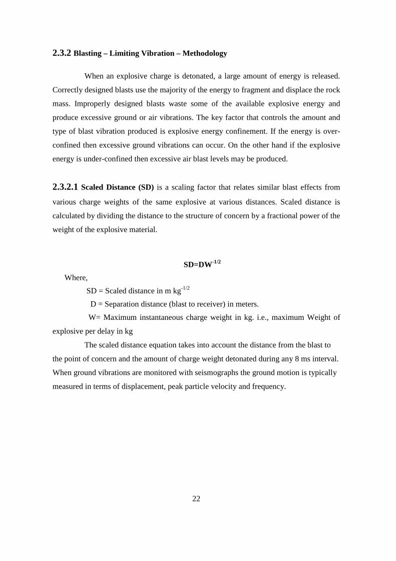
2.3.2 Blasting – Limiting Vibration – Methodology
When an explosive charge is detonated, a large amount of energy is released.
Correctly designed blasts use the majority of the energy to fragment and displace the rock
mass. Improperly designed blasts waste some of the available explosive energy and
produce excessive ground or air vibrations. The key factor that controls the amount and
type of blast vibration produced is explosive energy confinement. If the energy is over-
confined then excessive ground vibrations can occur. On the other hand if the explosive
energy is under-confined then excessive air blast levels may be produced.
2.3.2.1 Scaled Distance (SD) is a scaling factor that relates similar blast effects from
various charge weights of the same explosive at various distances. Scaled distance is
calculated by dividing the distance to the structure of concern by a fractional power of the
weight of the explosive material.
SD=DW-1/2
Where,
SD = Scaled distance in m kg-1/2
D = Separation distance (blast to receiver) in meters.
W= Maximum instantaneous charge weight in kg. i.e., maximum Weight of
explosive per delay in kg
The scaled distance equation takes into account the distance from the blast to
the point of concern and the amount of charge weight detonated during any 8 ms interval.
When ground vibrations are monitored with seismographs the ground motion is typically
measured in terms of displacement, peak particle velocity and frequency.

23
Table 7: Ground Vibration limits
Distance (ft) Scaled Distance
0 to 300 50
301 to 5000 55
Over 5000 65
Source: Determination of Blast Vibrations Using Peak Particle Velocity by Roy Nicholson There are two excepted scaled distance formulas used in blasting, square root scaling
and cube root scaling. Square root scaling is the general formula used in most regulations
and general blasting situations, where the charge can be considered linear. Cube root
scaling is used for blasting in the extreme near field where the charge can be considered a
point charge or in explosions involving very large quantities, such as those created by
nuclear explosions. Ambraseys and Hendron first suggested cube root scaling for use in
prediction of blast vibrations in the year 1968.
2.3.2.2 Square Root Scaling
Many times when construction-blasting specifications are encountered, designing to a
certain square root scaled distance factor is required. This is useful as a beginning
estimate for vibration control and provides a conservative and safe charge weight for the
test blast program. Since explosives confinement is not taken into consideration, there
can and usually is a large variation in results, especially in tight blasting situations. It
should be noted that small charges generate vibrations with higher frequencies and
smaller displacements.
Square Root Scaled Distance Formula Scaled Distance (SD) = (Distance Structure)/ (Weight) 0.5 Or, Weight = (D/SD) ²

24
2.3.2.3 Cube Root Scaling Cube root scaling should be used for vibration prediction in the extreme near field (under
20 feet) in construction blasting. Cube root scaling can also be used as the basis for the
prediction of frequency, but that will not be discussed here.
Cube Root Scaled Distance Formula
Scaled Distance (SD) = (Distance Structure)/ (Weight) 0.33
Or, Weight = (D/SD) ³
Ground Vibration is one of the major side effects of rock blasting which causes structural
damage. It cerates a great socio-economic problem for mine management as well as the
people residing in the vicinity of the blasting area. Hence, pre–operational judicious
planning is the key of efficiency, economy and environmental safety and it calls for in-
depth understanding of the character of ground, stability of the structure involved and
behaviors of explosives to be used.
2.4 Blasting damage
It appears that theoretical papers on blasting, that the precise nature of the
mechanism of rock fragmentation as a result of detonation of an explosive charge is not
fully understood. However, from a practical point of view, it seems reasonable to accept
that both the dynamic stresses induced by the detonation and the expanding gases
produced by the explosion play important roles in the fragmentation process.
Work on the strength of jointed rock masses suggests that this strength is
influenced by the degree of interlocking between individual rock blocks separated by
discontinuities such as bedding planes and joints. For all practical purposes, the tensile
strength of these discontinuities can be taken as zero, and a small amount of opening or
shear displacement will result in a dramatic drop in the interlocking of the individual
blocks. It is easy to visualize how the high pressure gases expanding outwards from an
explosion will jet into these discontinuities and cause a breakdown of this important
block interlocking. Obviously, the amount of damage or strength reduction will vary with

25
distance from the explosive charge, and also with the in situ stresses which have to be
overcome by the high pressure gases before loosening of the rock can take place.
Consequently, the extent of the gas pressure induced damage can be expected to decrease
with depth below surface, and surface structures such as slopes will be very susceptible to
gas pressure induced blast damage.
Hoek (1975) has argued that blasting will not induce deep seated instability in
large open pit mine slopes. This is because the failure surface can be several hundred
meters below the surface in a very large slope, and also because this failure surface will
generally not be aligned in the same direction as blast induced fractures. Hence, unless
a slope is already very close to the point of failure, and the blast is simply the last straw
that breaks the camel's back, blasting will not generally induce major deep seated
instability.
On the other hand, near surface damage to the rock mass can seriously reduce
the stability of the individual benches which make up the slope and which carry the haul
roads. Consequently, in a badly blasted slope, the overall slope may be reasonably stable,
but the face may resemble a rubble pile. In the case of a tunnel or other large
underground excavation, the problem is rather different. In this case, the stability of the
underground structure is very much dependent upon the integrity of the rock immediately
surrounding the excavation. In particular, the tendency for roof falls is directly related to
the interlocking of the immediate roof strata. Since blast damage can easily extend
several meters into the rock which has been poorly blasted, the halo of loosened rock can
give rise to serious instability problems in the rock surrounding the underground
openings.
It is a known fact that the safety and stability of underground mine openings, coal
pillars, water dams, ventilation and isolation stoppings close to operating open-pit mines
is often affected by blast induced vibration. As of today, there is an increasing trend in
India to win top coal seams, whether it is virgin or developed, by opencast workings
wherever it is economical. Mine operators attempt to get better fragmentation of rock
even if a blast requires high consumption of explosives per tonne of the mineral
produced, as improved fragmentation reduces the cost of loading, conveying and

26
crushing of minerals. These blasts generate seismic disturbances, which in turn may
damage the support system, ventilation/isolation stoppings, and water dams in
underground mines. It may induce opening of cracks in the strata rendering them
unstable. Also, there is possibility of spalling of coal in some adjoining workings that
may lead to spontaneous heating over a period of time. The seismic disturbances induced
by blasting depend on the total explosive energy released during blasting and the
nearness of the underground workings to operating open-pit mines. The quality of rock in
which an opening has been created can have a significant influence on the amount of
damage done by open-pit blasting. The size of bord and pillars, immediate roof rocks
whether laminated or shaley and the age of underground workings have significant
influence in sustaining the damage from seismic loading. Geo-mining conditions vary
from place to place. This introduces wide differences in effects produced by blasting
from mine to mine, necessitating individual study at different collieries. Therefore, under
the programme of study, seven sites were selected as experimental sites. The RMR of
each site was determined for evaluating its influence on damage resistance potential of
rock based on the CMRI-RMR classification
Rupert and Clark concluded that only minor damage in the form of localized thin
spalls and collapse of previously fractured coal ribs resulted from blast vibration
exceeding 50 mm/s. Jensen et al. reported no roof failure even at vibration level of 445
mm/s and only few loose stones at 127 mm/s. Kidybinski reported that damage to
underground coal mine openings in the form of small roof falls or floor heave may occur
when the PPV lies in the range of 50–100 mm/s and large roof falls at PPV of 100–200
mm/s. Fadeev et al. reported allowable values of vibration for various types of surface
and underground structures. In the case, of primary mine –openings (service life up to 10
years), viz. pit bottom, main cross entries and drifts, the allowable values reported were
120 mm/s for one fold blasting and 60 mm/s for repeated blasting. For secondary mine
openings (service life upto 3 years), viz. haulage breakthrough and drifts, the allowable
values suggested were 240 mm/s for repeated blasting and 480 mm/s for one fold
blasting. Fourie and Gree concluded that the PPV of 110 mm/s produced only minor
damage and extensive damage resulted when PPV was 390 mm/s. Singh et al.found that
the peak particle velocity of 48 mm/s did not cause any damage to the underground

27
workings. Tunstall suggested that peak particle velocity of 175 mm/s did not contribute
any damage to underground opening where very good quality rocks (RMR=85) were
encountered. On the other hand, the poor quality rock (RMR=49), which had been
loosened by previous open-pit blast vibration, sustained minor visible damage at a peak
particle velocity of 46 mm/s and major damage at a peak particle velocity of 379 mm/s.
Singh et al.observed that cracks in the coal roof occurred at peak particle velocity of
296.69 mm/s but spalling of coal chips from pillars and roof started at a vibration level of
125.3 mm/s. Lewandowski et al. set a conservative criteria of targeted maximum PPV of
50 mm/s for the safety of coal underground heading. They further clarified that this
conservative value of PPV was based on the damage observed at 250 mm/s.
Figure 6: Different damage zones based on ppv and rmr
Source: P.K. Singh (2002) 959–973

28
Figure 7: Distribution of blasting-related injuries in the mining industry.
Source: Blasting Safety - Revisiting Site Security By T. S. Bajpayee, Harry C.Verakis, and Thomas E. Lobb

29
Table 8: Classification of blasting damage
Sl. No Category Description of damage
(i) No appreciable damage No formation of noticeable cracks.
(ii) Threshold damage Formation of fine cracks, fall of plaster,
opening & lengthening of old cracks, loosening
of joints, dislodging of loose objects etc
(iii)
Minor damage
Superficial not affecting the strength of
structure(s). Hair line cracks in masonry
around openings near partition, broken
windows. Fall of loose mortar etc.
(iv) Major damage
Formation of several large cracks, serious
weakening of structures, shifting of foundation,
fall of masonry, ruptures of opening vaults etc.
2.5 Various standards regarding ground vibration Here we describes in detail the results and findings of statistical analysis of data
recorded during blasting in various types of rock mass in situ. It include limestone
(fissured and highly jointed), sandstone – alluvium, iron ore, basalt (Closely Jointed),
sandstone (Weathered), dolomite, granite (hard and fresh) and coal. Five empirical
equations are considered in predicting ground vibrations due to blasting. These include a
general form, inelastic attenuations characteristics and modified form of empirical
equations developed by CMRS. The finding would be helpful in designing blasting
patterns to protect nearby structures.
1. USBM PREDICTOR EQUATION
Considering Cylindrical explosive geometry for long cylindrical charges, Duvall and
Petkof (1959), Duvall and Fogelson (1962) and Duvall et al (1963) concluded that

30
any linear dimension should be scaled with the square root of the charge weight. They
assumed the relationship in the following form:
USBM: V = K (D/Q1/2)-B ………………………(1)
Where
V = Peak particle Velocity
D = Distance of measuring point
Q = Maximum Charge per delay in a round Blast
B= Slope of the best – fit straight line of the V versus D/Q1/2 plot in a log – log scale,
and K is the intercept on the particle velocity axis when D/Q1/2 = 1
2. LANGEFORS – KIHLSTROM EQUATION
Langerfors – Kihlstrom (1973) suggested the following relationship for various
charging levels {(Q/D3/2)1/2} to estimate Peak Particle Velocity.
LFKH: V = K {(Q/D3/2)1/2} B ……………………….. (2)
B is the slope of the best – fit straight line of the V versus (Q/D3/2)1/2 plot in a log – log
scale and K is intercept on the ordinate.
3. AMBRASEYS – HENDROM EQUATION
For spherical symmetry, Ambraseys – Hendron (1968) suggested that any linear
dimension should be called to the cube root of the charge weight. They also proposed an
inverse power law to relate amplitude of seismic waves and scaled distance . The
equation is –
AMHEN: V = K (D/Q1/3)-B …………………….. (3)
The empirical constants K and B are derived from the best - fit straight line of V versus
(D/Q1/3) in a log – log plot.

31
4. INDIAN STANDARD EQUATION
The empirical relation suggested by Indian Standard (1973) uses a parameter in which
blast is scaled to the equivalent distance or scaled distance. It is defined as the actual
distance divided by the cube root of the square of the charge weight. The relationship is
of the following form –
IS: V = K (Q2/3/D) B ………………………. (4)
5. CMRS PREDICTOR EQUATION
CMRS has established an efficient blast vibration predictor (pPal Roy, 1991) based on
wave propagation law. The equation considers only geometrical spreading as the cause of
the decrease amplitude of ground vibration.
The equation is –
V = n + K (D/Q1/2)-1 ……………………. (5)
The empirical constants “n” is related to the category of parameters, which are influenced
by rock properties and geological discontinuities. But, the empirical constant “k” is
related to the category of parameters which are influenced by design parameters
including charge weight, distance from the explosion source, charge diameter, delay
interval, burden, and spacing, sub drilling and stemming length. Table 1.9 lists the values
of empirical constants as well as the index of determination for different type of rock
mass insitu. The CMRS equation involves a very simple calculation for the determination
of charge per delay at any specific distance and the equation is as follows.
Q = [{D (v – n)}/K] 2
2.6 Control ground vibrations Blast design can be altered to result in reduced levels of ground vibration by:
Ø Reducing the maximum instantaneous charge (MIC) by using delays, reduced
hole diameter and/or deck loading.

32
Ø Blast vibration research shows the level of ground vibration is proportional to the
Scaled Distance (vibration), which is defined as the distance to the blast divided
by the square root of the MIC. So, at a given distance, reducing the MIC will
generally result in lower levels of vibration.
Ø Changing the burden and spacing by: altering the drilling pattern, and/or delay
layout, or altering the hole inclination.
Ø The optimum use of explosives in blasting occurs when the available energy is
efficiently used in fragmenting and moving the rock. When the hole inclination
(relative to the force angle) is decreased or the burden and/or opening are
increased, the explosive energy cannot fully fracture the rock and the energy
instead dissipates through the ground in the form of vibration.
Ø Exercise strict control over spacing and orienting all blast drill holes.
Ø Use the minimum practicable sub-drilling, which gives satisfactory toe
conditions. Less than optimum sub-drill in blast holes results in "toe" being left
after the blast, i.e. rock remains intact above the level of the previous bench floor.
Too great a sub-drill will result in higher levels of ground vibration due to
confinement of the explosives.
Ø Establish times of blasting to suit local conditions.
Here describes a method for controlling of blast vibration
2.6.1. Combination inter hole and inter row delays to minimize vibration
The method utilizes the existence of the local minimums in the frequency
spectrum of single-hole blast vibration. The results are presented as a delay map showing
maximum ground or structural vibration velocity for many combinations of inter hole and
inter row delays. A blast engineer can use this map to select an optimal combination of
delays that will produce a low vibration velocity at a selected location and, at the same
time, will be acceptable from the point of view fragmentation or muck pile shape.

33
2.6.2. Prediction and modeling of blast-induced vibrations
This method of predicting blast-induced ground vibration is based on the
establishment of an attenuation curve of vibration amplitudes. To develop a statistically
reliable curve, it is necessary to record as many blast-induced vibrations as possible. The
recorded maximum amplitudes of ground vibrations (PPV) are plotted as a function of
scaled distance. Scaled distance is usually defined as the ratio of the distance between the
blast location and the recording-station and the square root or cube root of the explosive
mass initiated within a certain time interval, usually 8 ms. The 8 ms interval is based on
the results of investigations that show longer time intervals effectively separate the
dominant part of the ground vibration due to individual holes in a single-row blast.
However, it is quite clear that this interval is site and blast-design specific (Anderson,
1989).
The second approach to blast-vibration modeling is limited to the linear aspects
of the generation and propagation of ground vibration. The essential part of this modeling
approach is the assumption that the vibration due to a single-hole blast can be used as an
elemental part of a multi hole blast-vibration model. In other words, the vibration induced
by the small blast can be used to build up a vibration signal for a large blast. A key
element in this approach is the assumption of a linear relationship between the elements
that constitute the model. A blast-vibration simulation model, based on superposition, is
illustrated in Figure 8. Basically, the model uses simple algebraic addition of vibration
waveforms due to each blast hole in the multi hole blast, shifted by appropriate delay and
travel times to build up the total blast-induced waveform.
2.6.3. Minimization of blast-induced ground vibrations
The difficulty in reducing ground vibration is that the minimization should be
achieved without adversely affecting the blast performance in terms of the volume of
blasted material, rock fragmentation and muck-pile shape. Assuming validity of the
single-hole blast linear superposition principle, the modulation function of a blast design
(amplitude spectrum of the initiation sequence) is an independent element of a blast-

34
induced vibration model. This function is not influenced by the single-hole blast
vibration. Minimization of a multi hole blast-induced vibration can be achieved by
minimizing the blast-design modulation function (initiation sequence). This function is
determined, for a given frequency range, by the amplitude scaling parameters and
effective delay times.
Figure 8: Principle of superposition of blast vibration waveforms
Minimization of blast vibration is restricted by the production requirements,
such as good fragmentation and muck-pile shape. This means short inter hole and inter
row delay times are not suitable. Hence, a practical blast design must use a delay
combination whose initiation-sequence spectrum has low frequency peaks that overlap
with the spectrum of a single-hole blast vibration. Hence, relatively small changes in the
delay times may cause either amplification or minimization of a multi hole blast-vibration
energy or amplitude relative to the same parameter for the single-hole blast.
This above method can be used to determine the optimal delay combination for
the blast design shown in Figure 9.The inter hole spacing and the burden are 10 m and the
reference location is 1,410 m from the nearest blast hole. The propagation velocity of the

35
seismic waves was 3,000 m/s. The maximum amplitude of the simulated vibration
velocity was used as the parameter for minimization. The single-hole blast vibration used
as a seed in the simulation has maximum amplitude of 0.08 mm/s.
Vibrations were modeled for inter hole and inter row delays ranging from 10 to
200 ms in steps of 10 ms. The result of the simulation is presented in the form of a delay
map shown in Fig. 9. This map shows a great diversity in the maximum values of the
blast-induced vibration caused by similar delay combinations. To compare two similar
delay combinations the blast vibration was modeled using a constant inter row delay of
100 ms and inter hole delays of 50 and 60 ms. The delay map indicates these two similar
inter hole delays produce very different maximum vibration velocities. The maximum
vibration amplitudes for the 50 and 60 ms inter hole delays are 0.55 and 0.18 mm/s
respectively. Both the above blast delay combinations are almost equally acceptable from
the point of view of burden relief and fragmentation. However, the second delay
combination is obviously a much better choice for minimizing vibration.
Figure 9: Bench blast design with delay

36
2.6.4. Presplitting Rock Excavation Slopes to reduce ground vibration
Presplitting is defined as the establishment of a free surface or shear plane in
rock along the specified excavation slope by the controlled use of explosives and blasting
accessories in appropriately aligned and spaced drill holes.
The presplitting technique, as covered herein, shall be used for forming rock
excavation slopes at the locations shown on the plans.
It has to remove overburden soil and weathered rock along the top of the
excavation for a distance of at least 15 m beyond the drilling limits, or to the end of the
excavation, before drilling the presplitting holes. Particular care and attention shall be
directed to the beginning and end of excavations to ensure removal of overburden soil
and weathered rock and to expose fresh rock to an elevation equal to the bottom of the
adjacent lift of the presplitting holes being drilled.
Slope holes for presplitting shall be drilled along the line of the planned slope
within the tolerances specified herein. The drill holes shall be not less than 65 mm, and
not more than 75 mm in diameter. The Contractor shall control the drilling operations by
the use of proper equipment and techniques to ensure that no hole shall deviate from the
plane of the planned slope by more than 300 mm nor shall the holes deviate from being
parallel to an adjacent hole by more than 67 percent of the planned horizontal spacing
between holes.
The length of presplit holes for an individual lift shall not exceed 9 m, unless
the Contractor can demonstrate to the Engineer that the Contractor can stay within the
above tolerances and produce a uniform slope. The length of holes may then be
increased to a maximum of 18 m. The spacing of presplit holes shall not exceed 0.9-m on
centers and shall be adjusted to result in a uniform shear face between holes.
Auxiliary drill holes along the presplit line, not loaded or stemmed, may be
ordered by the Engineer. Except for spacing, auxiliary drill holes shall conform to the
provisions for presplit holes.

37
It shall have to place the adjacent line of production holes inside the presplit
lines in such a manner that avoids damage to the presplit face. If necessary to reduce
shatter and over break of the presplit surface, the first line of production holes shall be
drilled parallel to the slope line at the top of the cut and at each bench level thereafter.
Blasting techniques that result in damage to the presplit surface shall be immediately
discontinued.
No portion of the production holes shall be drilled within 2.5 m of a presplit
plane except as approved by the Engineer. The bottom of the production holes shall not
be lower than the bottom of the presplit holes.
A maximum offset of 600 mm will be permitted for a construction working
bench at the bottom of each lift for use in drilling the next lower presplitting pattern. The
Contractor shall adjust the drilling operations to compensate for drift of previous levels
and for the offset at the start of new levels to maintain the specified slope plane.
If at times the methods of drilling and blasting do not produce the desired result
of a uniform slope and shear face without over break, within the tolerances specified, the
Contractor shall drill, blast, and excavate in short sections, up to 30 meters, until a
technique is arrived at that will produce the desired results. The maximum diameter of
explosives used in presplit holes shall not be greater than 50 percent of the diameter of
the presplit hole.
Only standard cartridge explosives prepared and packaged by explosive
manufacturing firms shall be used in the presplit holes. These shall either consist of
fractional portions of standard cartridges to be affixed to the detonating cord in the field
or of solid column explosives joined and affixed to the detonating cord in the field.
If fractional portions of standard explosive cartridges are used, the cartridges
shall be firmly affixed to a length of detonating cord equal to the depth of the drill hole so
that the cartridges will not slip down the detonating cord nor cock across the hole and
bridge the flow of stemming material. Spacing of cartridges along the length of the

38
detonating cord shall not exceed 750 mm center to center and shall be adjusted to give the
desired results.
The bottom charge of a presplit hole may be larger than the line charges but
shall not be large enough to cause over break. The top charge of the presplitting hole
shall be placed far enough below the collar to avoid overbreaking the surface.
Before placing the charge, the hole shall be free of obstructions for the hole's
entire depth. Necessary precautions shall be exercised so that placing of the charge will
not cause caving of material from the walls of the holes.
Stemming may be required by the Engineer whenever necessary to achieve a
satisfactory presplit face. Stemming materials shall be dry free-running material
100 percent of which passes a 9.5-mm sieve and 90 percent of which is retained on a
2.36-mm sieve. Stemmed presplit holes shall be completely filled to the collar. Charges
in each presplitting pattern shall be detonated simultaneously.
The presplit face shall not deviate more than 0.3-m from the plane passing
through adjacent drill holes, except where the character of the rock is such that, as
determined by the Engineer, irregularities are unavoidable. When completed the average
plane of the slopes shall conform to the slopes indicated on the plans and no point on the
completed slopes shall vary from the designated slopes by more than 0.3-m. These
tolerances shall be measured perpendicular to the plane of the slope. No portion of the
slope shall encroach on the roadbed.
As long as equally satisfactory presplit slopes are obtained, either presplit the slope face
before drilling for production blasting or shall presplit the slope face and production blast
at the same time, provided that the presplitting drill holes are fired with zero delay and
the production holes are delayed starting at the row of holes farthest from the slope and
progressing in steps to the row of holes nearest the presplit line, which row shall be
delayed at least 50 milliseconds. In either case, the presplitting holes shall extend either
to the end of the excavation or for a distance of not less than 15 m beyond the limits of
the production holes to be detonated.

39
Those holes that fail to meet the alignment controls specified herein will not be
accepted for payment. Holes that are drilled where the finish slope does not meet the
slope tolerances specified herein will not be accepted for payment. Only those holes that
qualify as to alignment and slope finish and which show a hole trace for approximately
50 percent of the drilled length will be accepted and measured for payment. No
compensation will be allowed for unacceptable presplit work. Evaluation of presplit
holes to determine if the holes qualify for payment will be made after excavation but
before slope trimming or cleanup work.
For fully acceptable presplitting holes, the length to be paid for will be the
theoretical slope length as computed from elevations, taken before detonating each lift,
and a plane one meter below finish grade. No payment will be made for drilling more
than one meter below finish grade unless additional drilling is directed by the Engineer.
For those holes which produce an acceptable slope and conform to all the tolerances and
requirements, except alignment within the plane of the slope, the length to be paid for
will be 75 percent of the theoretical slope length.
No adjustment of compensation which results in an increase in the contract
price will be made for any decrease in the final pay quantity for presplit drilling if the
decrease is a result of nonpayment for unacceptable drill holes or unacceptable work.
The provisions in Section 4-1.03B, "Increased or Decreased Quantities," of the Standard
Specifications shall not apply to increased prices because of decreases resulting from
nonpayment for unacceptable work.
2.6.5 Minimization of blast-induced structural vibrations
The important goal of blast-vibration monitoring is the minimization of blast-
induced vibration of structures. Minimization of induced structural vibration is a more
complex task than minimization of ground vibrations. The complexity is due to the
addition of two more parameters: the resonant frequency and the damping ratio.
A surface structure will amplify a ground vibration whose frequency is close to
its resonant frequency, and the intensity of amplification depends on the damping ratio of

40
the structure. Ground vibration with frequencies significantly higher than the resonant
frequency of a structure, will be effectively attenuated in the structure. Ground vibration
with frequencies lower than the resonant frequency of the structure will not be attenuated,
but amplification in the structure gradually decreases with the increasing difference
between two frequencies. Minimization of induced structural vibration can be performed
in two ways. The first involves determining the delay combination that will induce a
minimum value of the product between the complex valued spectrum of the simulated
ground vibration and the frequency-response function of the SDF system for a given
resonant frequency and damping ratio. This method is more suitable for cases where the
resonant frequency is not known or where more than one structure needs to be protected
from a strong blast-induced vibration. In such cases, the average value of the response
spectrum in the given frequency range is calculated, as is a constant value of damping
ratio. This parameter of the response spectrum is calculated for every simulated ground-
vibration record.
This method was used with the blast design presented previously (Fig. 5). For
each delay combination, the ground-vibration acceleration record was modeled and used
to calculate the related response spectrum. In the case when the exact resonant frequency
of the structure is not known or when more than one structure exists at the same location,
the optimal delay combination is one that will induce the lowest average vibration for all
structures. The average maximum vibration amplitude can be calculated as the average
value of the SDF-response spectrum within a predefined frequency range.
In this case, the resonant-frequency range of 10 to 20 Hz and a constant
damping ratio of 3% were chosen. The result of minimization is presented in the form of
a delay map. This delay map immediately shows which delay combinations should not be
used. For instance, the inter row delays of 40 to 90 ms with inter hole delays 50 to 100
ms induce relatively large structural vibration. On the other hand, a delay combination
consisting of 40-ms inter row and 25-ms inter hole or 110-ms inter row and 40ms inter
hole induce structural vibrations with very low maximum amplitudes.

41
CHAPTER: 3
Data Collection
Introduction
Description of Quarry Site
Surrounding Structures
Data Collection
Instrument used for Vibration Monitoring
Data analysis

42
CHAPTER 3
DATA COLLECTION:
3.1 Introduction:
This area lies at distance 170 km from Bhubaneswar. The nearest railway station
is Talcher on South Eastern railway at a distance of about 6 km from the project site. The
block is gently undulating with general slope towards north; small hillocks of
conglomerate horizon are prominent physical features to the south and south east.
It is said that only approximately 15% of the total energy of is utilized for actual
breakage and displacement of the mass while the remainder is spend on undesirable
activities. These undesirable activities are ground vibration, fly rock, noise fumes and
heat. Ground vibration is a major concern, as it can cause damage to surface structure and
extreme annoyance to residents within the vicinity of where the quarry situated. The
purpose of this study also was to establish some parameters and some form of criteria to
suggest optimal blast design considering the safety of these structures and the equipment
within.
3.2 Description of Quarry Site:
The Quarry is strategically located in terms of easy access and short haul distance to the
company’s coal handling plant. This quarry is surrounded by villages. The strike of the
beds is in east and west direction in general. The gradient of beds 1in 7 to 1 in 10 towards
north. The block is by 10 faults; throw ranging from 0m to as much as 100m.

43
Figure 10: Bharatpur opencast mine, M.C.L.
3.3 Surrounding Structures: The structures that were of much concern are those residences that were in close
proximity to the quarry. Houses are closer than 200meters to the quarry hence the need to
be concerned about all possible nuisance from the activities in the quarry. All the
structures in the village north of the quarry were constructed of reinforced concrete with
steel.
3.4 Data Collection:
Due to the sensitivity of the location of the quarry with respect to the houses, a decision
was taken by the Mines and Geology Division that all blasting activities must be
monitored for vibration levels. The purpose of this form of regulation was part and parcel
to help to prevent property damage as a result ground vibrations and air blasts from
blasting activities. Seismographs are the instruments used to ensure compliance for
blasting activities.
Adequate time was allowed for the setting up of the equipment. The instrument at no time
was placed closer than 1.3m away from the foundation of the closet structure with the

44
microphone mounted about 1m above ground with adequate air muff to prevent pre
mature trigger by high winds. The trigger levels were set at 1.2 mm/s for the geophone
and 0.03625 psi for the microphone. The location and distance from the quarry to the
closest building. The sensor was always adequately coupled to the ground and as level as
is possible with the radial channel pointing directly at the blast site. All the necessary
information with regards to explosive weight, atmosphere condition and any other
information that will ensure a true reading were done.
Explosives used: Emulsion type
Manufacturer: NGF ( Nababharat Fuse)
Depth: 8 – 8.5
3.5 Instrument used for Vibration Monitoring To collect all these data three seismographs were used at different time. The
Blastmate III of Instantel origin, have similar operation features to those of the
Geosonicbrand. They are all fitted with four channels, three channels for which, one
triaxial transducers for monitoring vibration in the Longitudinally, Transverse and
Vertical direction and one channel to monitor the sound.
A single instrumentation system is unlikely to meet all the requirements of
frequency and dynamic range under the wide range of situations for which this guideline
applies. In general, a vibration measuring system usually includes the following
instrumentation: transducers, typically piezoelectric accelerometers or geophones signal-
conditioning equipment a data recording and analysis system.
Consultants, engineers and contractors the world over recognize the Instantel®
Blastmate® III vibration and overpressure monitor as the most versatile and most
reliable full featured monitor available. It provides all of the industry-leading features of
the Instantel Minimate® Plus monitor, conveniently packaged with a full keyboard and
a high-resolution printer. This allows you to setup add notes and print complete event
reports in the field, without a computer.

45
INSTANTEL BLASTMATE III DS677 Key Features
Ø Fast high-resolution thermal printer for event reports in the field without the need
for a computer.
Ø Full keyboard simplifies entry of job-specific notes and information.
Ø Dedicated function keys and intuitive menu-driven operation enable quick and
easy setup.
Ø Histogram Combo mode allows capture of full waveform records while recording
in histogram mode.
Ø Sample rates from 1,024 to 16,000 S/s per channel up to 65,000 S/s available on a
single channel.
Ø Available 8-channel option allows for 2 standard triaxial geophones and 2
microphones to be used on a single Blastmate III monitor.
Ø Continuous monitoring means zero dead time, even while the unit is processing.
Ø Any channel can be matched to a wide variety of sensors - geophones,
accelerometers, or hydrophones.

46
3.5 Data analysis
SITE 1:
INSTANTEL DS677 BLASTMATE
SERIAL: 1856 U 5.52
CLIENT: MCL TALCHER
LOCATION: TALCHER
USER: ASHRIT- SANJIB
TRIGER SOURCE: GEO OR MIC
TRIGER LEVEL: 1.010 in/sec 0.03625 psi (L)
RECORD TIME: 4 s AUTO
CALIBRATED 27 JAN 2005 by CMRI DHANBAD
NOTES:
WET SOIL CONDITION
SCALES DISTANCE: 6.1
DISTANCE: 393.7 ft
WEIGHT/DELAY: 165 lb
TRIGGERED: AUTO AT 1:20:35 25 JAN 2007
TRAN VERT LONG
PPV 0.260 0.040 1.280 in/s
FREQ 3 N/A N/A Hz
TIME 2514 2744 3087 ms
ACCEL 0.21 0.05 0.21
PK DISP: 0.0266 0.0000 0.1345 ln
PVS 1.283 in/s AT 3087 ms
USBM RI8507 AND OSMRE ANALYSIS

47
Figure 11: Diagram showing data as against USBM criteria

48
SITE 2:
INSTANTEL DS677 BLASTMATE
SERIAL: 1856 U 5.52
CLIENT: MCL TALCHER
LOCATION: TALCHER
USER: ASHRIT- SANJIB
TRIGER SOURCE: GEO OR MIC
TRIGER LEVEL: 1.010 in/sec 0.03625 psi (L)
RECORD TIME: 10 s
CALIBRATED 27 JAN 2005 by CMRI DHANBAD
NOTES:
WET SOIL CONDITION
SCALES DISTANCE: 6.1
DISTANCE: 229.6 ft
WEIGHT/DELAY: 179.1 lb
TRIGGERED: AUTO AT 1:22:30 24 JAN 2007
TRAN VERT LONG
PPV 4.700 2.380 4.420 in/sec
FREQ 2 N/A 2 Hz
TIME 1979 514 1615 ms
ACCEL 1.06 0.80 0.80
PK DISP: 0.3508 0.3464 0.4067 ln
PVS 4.980 in/s AT 9229 ms
USBM RI8507 AND OSMRE ANALYSIS

49
Figure 12: Diagram showing data as against USBM criteria

50
SITE 3: INSTANTEL DS677 BLASTMATE
SERIAL: 1856 U 5.52
CLIENT: MCL TALCHER
LOCATION: TALCHER
USER: ASHRIT- SANJIB
TRIGER SOURCE: GEO OR MIC
TRIGER LEVEL: 1.010 in/sec 0.03625 psi (L)
RECORD TIME: 1 s
CALIBRATED 27 JAN 2005 by CMRI DHANBAD
NOTES:
DRY SOIL CONDITION
SCALES DISTANCE: 5.3
DISTANCE: 246.9 ft
WEIGHT/DELAY: 367 lb
TRIGGERED: AUTO AT 1:29:09 23 JAN 2007
TRAN VERT LONG
PPV 1.570 0.200 1.330 in/s
FREQ 7 8 2 Hz
TIME 10 -6 60 ms
ACCEL 0.29 0.19 0.27
PK DISP: 0.0458 0.000 0.0323 ln
PVS 1.752 in/s at 11 ms
USBM RI8507 AND OSMRE ANALYSIS

51
Figure 13: Diagram showing data as against USBM criteria

52
3.6 Results The data collected for blasting activities have shown that the PPV was sufficient to cause
any structural damage according to the standards put forward by the USBM. The PPV
ranges from a low of 32.5mm/s to a high of 126.4 mm/s which revealed that the vibration
intensities were not at bearable levels. In comparing such range with other standards it is
unlikely for such vibration to cause any structural damage to the buildings in close
proximity to the quarry.
The vertical waves recorded the highest PPV value at maximum at a level of 60.42 mm/s
which is above the 50mm/s recommended by the USBM standards. The vibrations were
monitored in terms of the peak particle velocity and from data collected it varied from a
low of 32.5 to126 mm/s. These were dependent on the amount of explosive detonated per
delay, the distance from the blast face the set up of the monitoring instrument on the
particular day. The highest level of vibration recorded was 126.4 mm/s at a distance of
70metres from the blast face. This 126.4 mm/s PPV lasted for approximately 0.025 of a
second. Although this level of vibration is tolerable for reinforced concrete structures
there is some concern. The reported quantity of explosives per delay was 81.3kg; one will
want to attribute the high vibration level to possible cooperating of charges or improper
coupling of transducers with ground.
53
CHAPTER: 4
Recommendations and
Conclusion
Recommendations
Conclusion

54
CHAPTER4
Recommendations and Conclusion: 4.1 Recommendations As stated previously, one of the major nuisances to human beings from blasting activities
is ground vibrations. Residents are at times more concerned about their property than
health. The slightest of vibration will lead to complaints related to property damage. The
blaster must ensure that all precautions are taken to minimize this vibration problem.
Residents rarely have any close observation and inspection to their property. As soon as
there is a blast and any vibration is felt, then all the cracks are now visible. To try and
alleviate the many complaints that might occur as in depth preblast inspection of the
property must be carried out. In doing this preblast inspection clear documentation of all
the visible cracks or any observed damaged to the structure must be made.
In doing this the blaster will have this document to refute any alleged complaints of
damage for blasting activities. Should there be a complaint the blaster may also apply the
strategy of setting up a seismograph at the complainant’s home on his next blast. Using
such a strategy along with the preblast document the blaster may be able to convince the
complainant that the property was not damaged by blasting activities.
When using a seismograph to monitor the vibration or air pressure there are
guidelines that must be followed. In following these guidelines it is quite likely that a
correct and authentic reading will result. Aspects such as the proper coupling of
transducers, the correct information typed into the machine and the correctly set trigger
levels are all necessary for accurate readings. In the reading of a seismograph, it is
important to note the frequency of each wave. Aves with low vibrations usually travel far
distance and can cause annoyance at distance where the PPV is very low.
These are not the only criteria that are necessary for the correct use of the
seismograph. More detailed information can be obtained from the USBM website. It is
also necessary to note that not all seismographs are programmed in the same way. The
user must have a good knowledge of how the specific monitoring machine functions. The
type of explosives and/or initiation system in a blast can influence the air pressure and
ground vibration. It is therefore necessary to have the specification by the manufacturer

55
as to his product. This may stem from shelf life to its sensitivity. With regards to the
Nobel shock tube air over pressure system is recommended over the traditional
detonating cord. It is likely to reduce the level of air over pressure. This Nonel system is
also a reputable substitute for the electric initiation system. It will do the work of the
electric detonators but are not vulnerable to the many electric hazards.
The blaster should ensure that he has a well designed blast. In doing so all
precautions must be taken into consideration. The entire blasting activity should be a
process starting from the drilling of the holes. A thorough record of each hole must be
available for the proper loading of each hole to prevent over loading of the explosives.
Use the appropriate explosives and initiation system that will foster maximum use of
energy and limited amount of nuisance.
Finally it is necessary for all users to be familiar with the latest technology in the
use of explosives. They should aware of international limitations and criteria and be
knowledgeable about those that are stipulated for your area. This is likely to provide you
with the necessary knowledge to produce better blasts with limited nuisances.
4.2 CONCLUSION The blast vibrations generated and propagated were high to cause damage to the
structures in the nearby village. The Maximum Vertical Peak Particle Velocity of
60.42mm/s was recorded near the foundation of the security house. In conclusion, it was
not possible to cover all the aspects that contribute to ground vibration. All the blasts
recorded did not fall well within the safe limit. The analysis of the data has lead to the
conclusion that the quarry can not be expanded in the direction of village side.
The environmental problems arisen from ground vibration and air blast have been
faced and discussed frequently in various industries such as mining, construction, quarry
etc. where blasting operations are unavoidable. So the ground vibration effects induced
by blasting on structures and human beings need to be predicted, monitored, and
controlled. With the increase of the environmental constraints on the levels of disturbance
induced by blasting operations nearby residents, there is also an increasing necessity to
design cautious blasting with greater precision. Therefore, the determination of maximum

56
amount of explosive per delay for a certain distance, especially in large blasts, has a great
importance for the elimination of these environmental problems.
Evaluation of the damage risk of the ground vibration induced by blasting Therefore
it will be necessary to control the blasting and to predict the level of vibration in order to
prevent the damage to the buildings located nearby this site and to reduce these
complaints within the scope of the study, ground vibration components were measured
for 3 events using Blastmate III considering the directions of the village, in order to
predict the peak particle velocity ,the maximum charge per delay, and for the evaluation
of the damage risk.

57
REFERENCES:
1. Anderson, D.A., 1989, "The 8 millisecond 'criterion': Have we delayed too long in
questioning it?," Proc. 15th Conf. on Explosives and Blasting Technique, Soc. of
Explosives Engineers, New Orleans, LA
2. Blair, D.P., 1987, "The measurement, modeling and control of ground vibrations
due to blasting," Proc. 2nd Int. Symp. on Rock Fragmentation by Blasting,
Keystone, CO
3. Pilant, W.L., and L. Knopoff, 1964, "Observations of multiple events," Bull.
Seismol. Soc. Am., Vol. 54, No.1, pp.19-39. Siskind, D.E., M.S. Stagg, JW.
Kopp, and C.H. Dowding,1980, "Structural Response and Damage Produced by
Ground Vibrations from Surface Blasting," USBM Ri 8507.
4. Stump, B.W., and R.E. Reinke,1988,"Experimental confirmation of superposition
from small-scale explosions," Bull. Seismol. Soc. Am., Vol. 78, No. 3, pp.1059-
1073.
5. DGMS (Tech) (S&T) Circular No.7 of 1997 Dhanbad, dated the 29th August,
1997.
6. Northwood, T.D., R. Crawford and A.T. Edwards. Blasting vibrations and
building damage. The Engineer, Vol. 215, No. 5601, 31 May 1963, p. 973-9.
7. Indian Standard: Criteria for safety and design of structures subjected to blast, ISI
BUL. NO IS – 6922, (1973).
8. Duvall W I and fogelson D E: Review of criteria for estimating damage to
residence from blasting vibrations, USBM – Rl 5968, (1962)
9. Assessing Vibration: a technical guideline (February 2006) by: Department of
Environment and Conservation 59–61 Goulburn Street Sydney NSW 2000
10. Blast vibration damage to underground coal mines from adjacent open-pit blasting
by: P.K. Singh, Central Mining Research Institute, (6 September 2002).

58
11. Research papers from NIOSH website.
12. Determination of Blast Vibrations Using Peak Particle Velocity
By: Roy Fitzgerald Nicholson.