evaluation of deep in-situ soil stabilization by high...
TRANSCRIPT

Evaluation of Deep In-Situ Soil Stabilization by High-Pressure Lime-Slurry Injection H. L. LUNDY, JR., and B. J. GREENFIELD, Swindell-Dressler Company,
Pittsburgh, Pa.
During the fall of 1965, a soft glacial clayey silt deposit was pressureinjected with a hydrated lime slurry to depths of 20 feet to determine the effects of the lime on the stabilization of the foundation beneath a 40-foot highway embankment in Pennsylvania. Field sampling programs, visual observations and laboratory testing programs were conducted up to one year after the lime slurry was injected. The laboratory testing data on treated and untreated lime samples are discussed in this paper.
High pressure lime-slurry injection was moderately successful in forcing a slurry uniformly into the soft clayey silt deposit. The physical characteristics of the treated soil generally appeared to remain unchanged after one year of in-situ curing, with the exception of the shear strengths which increased.
The results of the project reveal a definite usefulness for the high pressure lime-slurry method of in-situ stabilization in cohesive soils. Need for future investigation leading to successful, practical design applications is discussed.
•HYDRA TED lime, used to increase the shearing strength of plastic soils at or near the ground surface, has experienced a great deal of success in the past decade. Basically, this method of soil stabilization consists of mechanically mixing proper amounts of hydrated lime and soil and allowing this mixture to mellow before compaction. The ensuing reactions of the mixture reduce the plasticity and increase the shearing strength of lime-reactive soils. Since surface stabilization has obtained favorable results, it follows that some type of subsurface stabilization, 3 ft or more below the ground surface, may be possible. This paper presents the results of an experimental project of stabilizing the foundation for a proposed highway embankment by high-pressure limeslurry injection to depths up to 20 ft.
In June 1965, the Swindell-Dressler Company, a Division of Pullman Incorporated, under contract with the Pennsylvania Department of Highways, initiated an experimental project involving subsurface lime stabilization of a deep, soft glacial lake bed using highpressure injection of a hydrated lime slurry. The initiation of this project resulted from the proposed construction of a 40-ft highway embankment over the soft glacial lakebed deposit. A feasibility study involving construction of sand drains, lightweight embankments, embankment counterweights, a bridge, and/or the excavation of the foundation material resulted in the initiation of this project to determine whether deep in-situ lime stabilization could be used to increase the shearing strength of the foundation soils and, therefore, provide adequate support of the highway embankment.
SITE LOCATION
The area of the test site, located 2. 5 miles northeast of Portersville on US 422 in the west-central section of Pennsylvania, is a finger of an old glacial lakebed
Paper sponsored by Committee on Lime and Lime-Fly Ash Stabilization and presented at the 47th Annual Meeting.
27

28
60' GLACIAL A-4(8) C• 200LB /FT. 2
known as Lake Watts. The top 6 to 8 ft of the test site deposit is a stiff mottled gray-brown clay of post glacial origin. This material is underlain by about 60 ft of soft wet gray varved clayey silt deposited during the time of the glacial lake.
Figure 1. Cross section of lakebed deposit and embankment.
The gray-brown clay, hereafter referred to as the post-glacial deposit, generally classified as an A- 7- 6 soil having an average cohesion of about 1200 psf. The deeper soft clayey silt, referred to as the glacial deposit, classified as an A- 4(8) soil having an average cohesion of about 200 psf . Empankment stability analyses were conducted using the results of unconsolidated-undrained triaxial shear tests.
Figure 1 shows a cross section bankment.
of this glacial lakebed area and the proposed em-
PURPOSE
The purposes of this experimental project were to determine whether or not the shearing strength would be increased in soils injected with a lime slurry to depths up to 20 ft; to pressure inject a lime slurry to depths up to 20 ft and obtain reliable horizontal and vertical injection patterns; to evaluate the horizontal penetration distance of the injected lime slurry; to evaluate the migration (vertical movement) of the lime slurry at various time periods following completion of the injection process; and to determine the effects of injected lime slurry on the physical properties of the soil.
This paper describes and evaluates the following:
1. Lime-slurry pressure-injection method of soil stabilization; 2. Results of the field soil sampling programs; 3. Results of the laboratory testing program; and 4. Effects of stabilization by the high-pressure lime-slurry injection method on
subsurface soils .
CONSTRUCTION OF LIME-STABILIZED TEST MATS
The first phase of the field construction program was the completion of three 6-in. deep lime-stabilized test mats approximately 50 by 50 ft. These mats were constructed using routine surface lime -stabilization techniques. The top soil was removed prior to scarification of the post glacial soil and 5 percent of lime by weight was added, mixed with the soil and allowed to mellow for 3 days. The test areas were then properly compacted to 95 percent standard Proctor density with a sheepsfoot roller, and final rolling was performed using a D-6 dozer.
The three test mats, located in the areas chosen for the lime-slurry injection, were constructed to permit free movement of construction equipment during the lime-slurry injection process and to reduce the amount of lime slurry breaking through the ground surface during the injection process.
Although the project dealt with high-pressure lime injection, block samples were obtained from the test mats. Unconfined compression test results conducted on the samples obtained only 8 days after completion of the mats showed a 50 percent increase in shearing strength. This increase was not as large as expected because of the unusually cool October temperatures which occurred during the 8-day test period. Past research has shown that lime-soil reactions effectively occur at temperatures above 60 F.
LIME-SLURRY INJECTION PROCESS
The second phase of the project consisted of injecting a lime slurry into the soil to depths of 20 ft in a manner that would permit a complete study and analysis of the horizontal and vertical injection patterns as well as to obtain undisturbed samples for laboratory testing and evaluation.

IHJ<CTIOI' AOO
LIME St.UAAY SEAM IHOAIZONTAL PENETRATION)
IHtXCTIOH NOZZLE
MIClRAT10H (VEIHICAL MOVEMENT)
Figure 2. Injection process.
29
The process of injecting a lime slurry into the subsurface to depths over several feet is a new and relatively untired technique. The concept of highpressure injection used on this project differs from standard grouting techniques where the voids of a granular soil are filled with a chemical compowid. In the lime-injection method, a slurry under high pressure is forced horizontally into the soil by rupturing the in-situ structu1·e and is forced along existing cracks and fissures. After a sufficient period of time, the lime apparently migrates (moves vertically) through the soil and reacts with the soil, thereby in
creasing the soil's shearing strength (Fig. 2). Completely automatic equipment was used to inject, at pressures of 300 and 600 psi,
specified quantities of slurry at the desired levels. Eight to twelve gallons of slur1·y were injected every 8% in. as the nozzle moved downward. The slurry used throughout the p1·oject was a mixture of 30 percent lime and 70 percent water by weight.
The slurry was injected at intervals beginning at 18 in. below the ground surface and continued to the desired depths. The injection nozzle was tapered to help prevent leakage up along the drill rod and to make a self-sealing hole as the rod was advanced into the soil (Fig. 2) .
Although the injection bit was tapered, quantities of lime slurry broke through the mats around the injection rod and as far as 10 ft away from the injection hole. These breakthroughs were manually suppressed in areas away from the injection rod. However, the leakage was considerable and difficult to control at the injection rod. This loss, estimated at approximately 25 percent, usual!ly occurred when the injection bit was in the deeper soft clayey silt. Since the soft glacial soil did not hold a tight seal against the injection nozzle, the slurry followed the path of least resistance and was lost by fl.owing back up along the outside of the injection rod. This loss of slurry indicated that the lime did not penetrate the softer soil to the extent that it did in the harder post-glacial material. This was later confirmed during the soil sampling programs.
SUBSURFACE EXPLORATION PROGRAM
After the completion of the lime-slurry injection, three subsurface exploration investigations were conducted. These investigations entailed the construction of trenches for visual observations (horizontal and verti.cal) of the injected lime and soil borings which included standard penetration testing to determine the horizontal and vertical locations of the injected lime and 2%-in. undisturbed thin-wall sampling for laboratory testing.
The first sampling phase, conducted one month after the lime-injection program, included a trench 3 ft wide and 8 ft deep located between two rows of injection holes and 4 soil borings located. on one test site.
The second sampling phase, conducted three months after the lime-injection program, included 18 soil borings located on two test sites.
The third and final sampling phase, conducted one year after the lime-injection program, included a 3-ft wide by 8-ft deep trench located between two rows of injection holes and 33 soil borings located on two test sites.
The three soil sampling phases included a total of 57 soil borings, 492 linear feet of sampling, 240 standard penetration tests and 108 undisturbed thin-wall samples.
The subsurface exploration program determined the horizontal and vertical locations of the injected lime slurry, indicating the success of the injection process Also, this exploration was conducted to obtain undisturbed samples for visual and laboratory analyses.
During the first soil sampling phase a trench was constructed parallel to two rows of injection holes with the face of the trench located about 5 ft from a line of injection holes. To help visually demonstrate the injected lime patterns, a
30
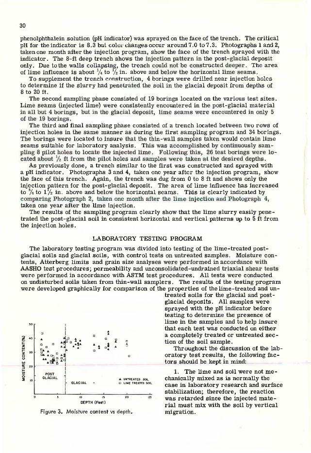
phenolphthalein solution (pH indicator) was sprayed on the face of the trench. The critical pH for the indicator is 8.3 but color changes occur around 7.0 to7 .3. Photographs 1 and2, taken one month after the injection program, show the face of the trench sprayed with the indicator. The 8-ft deep trench shows the injection pattern in the post-glacial deposit only. Due to the walls collapsing, the trench could not be constructed deeper . The area of lime influence is about % to % in. above and below the horizontal lime seams.
To supplement the trench construction, 4 borings were drilled near injection holes to determine if the slurry had penetrated the soil in the glacial deposit from depths of 8 to 20 ft.
The second s ampling phase consisted of 19 borings located on the various test sites . Lime seams (injected lime) were consistently encountered in the post-glacial material in all but 4 borings, but in the glacial deposit, lime seams were encountered in only 5 of the 19 borings.
The third and final sampling phase consisted of a trench located between two rows of injection holes in the same manner as during the first sampling program and 34 borings. The borings were located to insure that the thin-wall samples taken would contain lime seams suitable for laboratory analysis . This was accomplis hed by continuously sampling 8 pilot holes to locate the injected lime . Following this, 26 test borings were located about % ft from the pilot holes and samples were taken at t he desi.red depths.
As previously done , a trench similar to the first was constructed and sprayed with a pH indicator. Photographs 3 and 4, taken one year after the injection program, show the face of this trench. Again, the trench was dug from 0 to 8 ft and shows only the injection r,attern for the post-glacial deposit. The area of lime influence has increased to % to l /2 in. above and below the horizontal seams. This is clearly indicated by comparing Photograph 2, taken one month after the lime injection and Photograph 4, taken one year after the lime injection.
The results of the sampling program clearly show that the lime slurry easily penetrated the post-glacial soil in consistent horizontal and vertical patterns up to 5 ft from the injection holes.
LABORATORY TESTING PROGRAM
The laboratory testing program was divided into testing of the lime-treated postglacial soils and glacial soils, with control tests on untreated samples. Moisture contents, Atterberg limits and grain size analyses were performed in accordance with AASHO test procedures; permeability and unconsolidated -undrained triaxial shear tests were performed in accordance with ASTM test procedures. All tests were conducted on undisturbed soils taken from thin-wall samplers. The results of the testing program were developed graphically for comparison of the properties of the lime-treated and un-
50
t 4 0
1-z ... ~ 30 0
" ... a: 20
~ 0 :I 10
0
POST GLACIAL
0
GLACIAL
10
DEPTH (Feet )
• •
a
• UNTREATED SOIL O LIME TREATED SOIL
20
Figure 3. Moisture content vs depth .
treated soils for the glacial and postglacial deposits. All samples were sprayed with the pH indicator before testing to determine the presence of lime in the samples and to help insure that each test was conducted on either a completely treated or untreated section of the soil sample.
Throughout the discussion of the laboratory test results, the following factors s.nould be kept in mind:
1. The lime and soil were not me chanically mixed as is normally the case in laboratory research and surface stabilization; therefore, the reaction was retarded since the injected material must mix with the soil by vertical migration .

l
2. The reaction of the lime and soil are dependent on the amount of lime migration into the in-situ soil. Since these soils had permeabilities ranging from 0.1 to 12 in. per year, large migration of the slurry could not be expected for several years. From past research by R. L. Handy and L. K. Davids on, the rate of calcium migration expressed in the form d = k {[, resulted in a k value of 0. 081 in. /day, where d is distance, t is time and k is a constant depending on soil factors. On this project the k values were 0. 085 and 0. 067 in./day after one month and one year, respectively. This is in reasonably close agreement with the past research on rates of calcium migration.
30 POST GLACIAL DEPOSIT
)(
~ 20 ;!!;
GENERAL AAS.H.0. CLASS. A-7-6
10 20 30
LIQUID LIMIT(%)
a
31
• UNTREATED SOIL 0 LIME TREATED SOIL
o• a
40
D D
45
a a
Figure 4. Plasticity index vs liquid limit.
3. The ground temperature at which the reactions occurred was between 45 and 48 F, which is substantially below minimum temperature recommended for proper curing.
Post-Glacial Deposit
Moisture Contents-Figure 3 indicates that the moisture content prior to injection of the slurry and one year after the slurry injection remained unchanged. This was expected for the following reasons:
1. The lime was injected in slurry form (70 percent water), so initial absorption of moisture could not occur. This is contrary to surface stabilization where dry hydrated lime is used and the initial drying action is due to the adsorption and evaporation of water during mixing and manipulation.
2. The low permeabilities, ranging from 0. 1 to 12 in. /year, and a small driving head prevented significant movement of any freed pore water. Although the cation exchange (Ca++ replacing bonded water) releases the oriented pore water, the soil's low permeability resulted in the moisture content remaining unchanged.
Atterberg Limits-Figure 4 indicates that a slight reduction in the plasticity index occurred in the treated soils. This reduction, reported in previous laboratory research, is due to flocculation, agglomeration, cation exchange and pozzolanic reactions .
A marked reduction in the plasticity index has been achieved in field and laboratory testing where lime and soil are mechanically mixed and exposed to the air. However, on this project, migration of the lime is the only way that the soil and lime could inter
mix and react. After one year under field conditions, the reactions are not believed to be com-
0000 · POST GLACIAL DEPOSIT - - - UNTREATED SOIL
"' "' ... a: t; t OQO a: c ... ili
GENERAL A A.S H.O. CLASS .A-7-6
ONL'I' SAMPLES E>CHIBITING COMPLETE LIME MIGRATION AKO iN'OT CONT1UH1NO LIME S(AMS
-LIME-TAUTED SOIL
o 4000 GOOO eooo ~000 12,000 14,000
NORMAL STRESS (P.S.F.)
Figure 5. Shear stress vs nonnal stress.
plete. Therefore, the reduction in plasticity index was nominal.
Particle Size-Grain size analyses for lime-treated and untreated soil, indicate that no change in the particle sizes has occurred. This can be attributed to the following:
1. As previously mentioned, only partial flocculation, agglomeration, cation exchange and pozzolanic reaction have occurred. These partial reactions may not

32
8000
POST GLACIAL DEPOSIT GENERAL A AS.H_O. CLASS. A-7-6
B IC)
- --UNTREATED SOIL -LIME-TREATED SOIL -....-IUOICATES LIME SEAM
ONLY SAMPLES EXHIBITING COMPLETE LIME MIGRATION AND NOT CONTAINING LIME SEAMS
zo UNIT STRAIN(%)
Figure 6, Deviator stress vs unit strain.
be significant enough to appreciably alter the particle sizes.
2. What may be more significant is that these partial reactions may not be strong enough toresist the standard laboratory procedures conducted when preparing samples for testing. Specifically, the dispersant used in the test may reduce flocculation and agglomeration effects . This could easily destroy these weak lime-soilreactionsandgive results which show no change in particle size.
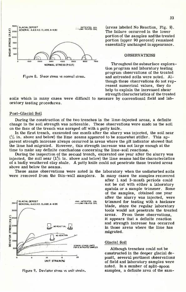
Shear Strength-Figure 5 indicates that no appreciable strength increase has occurred except for the two lime -treated samples noted. Figure 6 also indicates that strength increases did not occur and that the elastic properties of the lime-treated and untreated soil remained essentially the same.
Failure sketches of the lime-treated samples are included in Figure 6 to illustrate the type of failures and the reason for the lack of strength increase. All treated samples contained lime seams and failed along these seams except for the two s amples noted . Therefore, the triaxial tests were only indicative of the strength on the plane of the lime seam and not of the reacted soil. Visual observations indicate the magnitude of strength increases which have actually occurred.
Glacial Deposit
Moisture Contents-Figure 3 indicates, as it did for the post-glacial deposit, that the moisture content prior to injection of the slurry and one year after the slurry injection remained unchanged. This was expected for the reasons listed previously.
Atterberg Limits-Figure 7 indicates that the plasticity index has remained essentially unchanged. As previously mentioned, due to the incomplete reactions under the field conditions of the project, an appreciable change in the plastic properties was not expected.
Particle Size-Grain size analyses for lime-treated and untreated soil, indicate that no change in the particle sizes has occurred. As previously discussed, this is attributed to the incomplete reactions and the inability of these reactions to resist the destructive laboratory procedures used when preparing samples for testing.
Shear Strength-Figure 8 indicates that a more than twofold strength increase has occurred for the limetreated samples.
Figure 9 also indicates that strength increases occurred and that the plastic soil showed brittle failure properties when treated with lime. Three of the treated samples showing strength increases exhibited plastic failure properties . To illustrate the reason for these failures, sketches of the samples after testing are included. The bottom of these three samples was untreated
30
GLACIAL DEPOSIT !! zo GENERAL A,A.S.H.O. CLASS.A-4(8)
)(
~ 20
!!: ~ 15
u
~ 10 <( ..J Cl.
0 10 :20 25 30
LIQUID LIMIT(%)
..._ UNTREATED SOIL o LIME TREATED SOIL
40 •• • O
Figure 7. Plasticity index vs liquid limit.
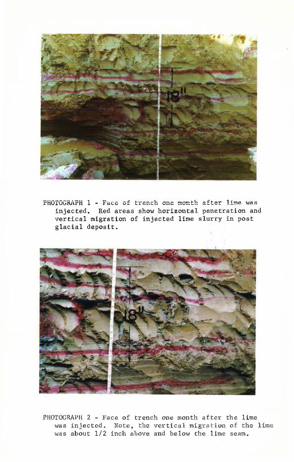
PHOTOGRAPH l - Face of trench one month after lime ~as injected. Red areas show horizontal penetration and vertical migration of injected lime slurry in post glacial deposit.
PHOTOGRAPH 2 - Face of trench one month after the lime was injected. Note, the vertical migr a t ion o f the lime was about 1/2 inch above and below the lime seam.

PHOTOGRAPH 3 - Face of trench one year after lime was injected. Red areas show horizontal penetration and vertical migration of injected lime slurry in post glacial deposit. Note that the lime slurry seams are white prior to spraying with pH indicator.
PHOTOGRAPH 4 - Face of trench one year after lime was injected. Note, the vertical migration of the lime was about 3/4 to 1-1/2 inches above and below the lime seam.
33
3000 GLACIAL DEPOSIT -- - UNTREATED SOIL (areas labeled No Reaction, Fig. 9).
The failure occurred in the lower portion of the samples and the treated portion (upper 90 percent) remained essentially unchanged in appearance.
~ i500 GENERAL A AS H 0 CLASS, A-4(8) -LIME- TREATED SOIL
0.:
::i 200 0
~ 15CJO
Iii a:: 1000
"' "' :i:: 000
"' 0 IOOO
OBSERVATIONS 3000 4000 7000
NORMAL STRESS (P.S.F.l Throughout the subsurface explora-tion program and laboratory testing program observations of the treated
Figure 8. Shear stress vs normal stress. and untreated soils were noted. Although these observations do not represent numerical values, they do help to explain the increased shear strength characteristics of the treated
soils which in many cases were difficult to measure by conventional field and laboratory testing procedures.
Post-Glacial Soil
During the construction of the two trenches in the lime-injected areas, a definite change in the soil strength was noticeable. These observations were made as the soil on the face of the trench was scraped off with a putty knife.
In the first trench, excavated one month after the slurry was injected, the soil near (% in. above and below) the lime seams appeared to be somewhat stiffer. This apparent strength increase always occurred in areas where the pH indicator showed that the lime had migrated. However, this strength increase was not large enough at the time to make any definite conclusions concerning the lime-soil reactions.
During the inspection of the second trench, excavated one year after the slurry was inj.ected, the soil near (1 % in. above and below) the lime seams had the characteristics of a badly weathered clay shale. A putty knife could not penetrate these treated areas above and below the seams.
These same observations were noted in the laboratory when the undisturbed soils were removed from the thin-wall samplers. In many cases the samples recovered
after 1 and 3-month periods could not be cut with either a laboratory spatula or a sample trimmer. Some of the samples, obtained one year
GL ACIAL DEPOSIT 3500 GENERAL A A S,H O. CLASS. A-4 (8)
IIIIIm UNTREATED SOIL -LIME-TREATED SOIL
gi 2
~ Ul I 0::
I? .. , > ~
0
u"NO REACTION~~
<O
UNIT STRAIN(%)
STRESS-STRAIN L IMITS FOR 8 UNTREATED SAMPLES
20
Figure 9. Deviator stress vs unit strain.
after the slurry was injected, were trimmed for testing with a hacksaw blade, since the regular laboratory tools would not penetrate the treated areas. From these observations, it appears that a definite reaction and strength increase has occurred in those areas where the lime has migrated.
Glacial Soil
Although trenches could not be constructed in the deeper glacial de -posit, several pertinent observations of field and laboratory samples were noted. In a number of split-spoon samples, a definite area of the sam-

34
ple held its original shape (that of the spoon) when the sampler was opened; in other areas soil in the spoon sample quickly lost its shape and flattened out. These more stable areas showed a pH reaction when the indicator was applied. This observation confirmed that the lime-soil reaction had strengthened the soil.
The majority of samples taken in the glacial deposit, which showed a pH reaction, did not have visible lime seams such as in the post-glacial deposit, indicating that migration in the glacial deposit was more extensive than in the post-glacial. Apparently this was due to the fact that the glacial material was originally coarser grained and thus more permeable.
CONCLUSIONS
1. Shear strength increases occurred in the in-situ soils treated by the lime slurry. The strength increases were observed one year after the lime slurry was injected and to depths up to 20 ft.
2. The magnitude of the strength increase in the soil one year after injection of the lime slurry was difficult to determine accurately by laboratory testing. Although the third sampling program was extensive, only a few samples recovered were completely reacted with the lime and did not contain a lime seam. Those samples which were completely reacted and did not contain lime seams showed an appreciable strength increase.
3. The moisture contents, plasticity indices and particle sizes of the lime-treated samples were not appreciably altered after one year of curing time, except for the plasticity index of the post-glacial soil.
4. A one-year waiting period between slurry injection and laboratory testing is not sufficient time for the complete occurrence of lime -soil r eactions under the conditions on this project.
5. The field method of lime-slurry injection was successful in penetrating the postglacial deposit, but only moderately successful in penetrating the glacial deposit.
6. The high-pressure lime - slurry method of soil stabilization can be used successfully to s tabilize soft soils beneath proposed highway embankments provided that injection equipment and additives can be developed which will aid in the penetration and migration of the lime into the soil.
NEED FOR FURTHER INVESTIGATION
This project has demonstrated that high-pressure injection of a lime slurry into a clayey soil at depths up to 20 ft to increase the shearing strength of soils can be accomplished. To date, little research has been conducted on the effects of high-pressure soil stabilization on soft clayey soils and to our knowledge no one has tried to measure the undisturbed strengths of pressure - injected lime -treated soils. Further research into the strength increases of clayey soil, 20 ft and deeper below the ground surface, should be undertaken to better determine effects of high-pressure soil stabilization by lime injection.
The following suggestions are offered for future research:
1. The field injection equipment should be modified considerably to insure that the injected slurry is more effectively and accurately forced into the subsurface.
2. Actual test embankments should be constructed on treated and untreated test areas to study the effects of consolidation on the migration of the lime slurry and to observe the stability of the treated versus untreated areas.
3. More extensive sampling and test-ing programs providing 1 on ge r curing periods between injection and testing are suggested to obtain more laboratory data documentation of strength increases.
4. Introduction of additives into the slurry to increase the speed of the reac-
The color plates on the following pages (center fold) were provided by the authors through the courtesy of Swindell-Dressler Company, Pittsburgh, Pa., and the National Lime Association, Washington, D. C.
35
tion, increase of the migration, and increase the strength of the treated soils should be attempted and analyzed.
ACKNOWLEDGMENTS
The authors would like to acknowledge the assistance of the following organizations and individuals: The Pennsylvania Department of Highways and W. S. Stephens, District Engineer; The National Lime Association, Washington, D. C.; The Pittsburgh Sales Office of the National Gypsum Company.
Special acknowledgment is made to Joseph R. Compton, Chief, Embankment and Foundation Branch, Soils Division, U.S. Waterways Experiment Station, Vicksburg, Miss., and Marshall R. Thompson, Assistant Professor of Civil Engineering, University of Illinois, for their assistance in the final review of this Report.
Acknowledgment is made to Leo D. Sandvig, Director, Donald L. Keller, Chief Soils Engineer, and Richard H. Howe, Soils Engineer, Materials, Testing and Research, Pennsylvania Department of Highways, for their review.
REFERENCES
1. Anday, M. C. Accelerated Curing for Lime-Stabilized Soils. HRB Bull. 304, p. 1-13, 1961.
2. Eades, J. L., and Grim, R. E. A Quick Test to Determine Lime Requirements for Lime Stabilization. Highway Research Record 139, p. 61-72, 1966.
3. Eades, J. L. , Nichols, F. P., Jr., and Grim, R. E. Formation of New Minerals with Lime Satbilization as Proven by Field Experiments in Virginia. HRB Bull. 335, p. 31-39, 1962.
4. Glenn, G. R., and Handy, R. L. Lime-Clay Mineral Reaction Products. Highway Research Record 29, p. 70-82, 1963.
5. Haynes, J. H., and Mason, R. C. Subgrade Soil Treatment at the Apparel Mart. International Research and Engineering Conference on Expansive Clay Soils, Dallas, Texas.
6. Herrin, M., and Mitchell, H. Lime-Soil Mixtures. Illinois Cooperative Highway Research Program Series No. 8, Univ. of Illinois, 1962.
7. Johnson, A. W. Soil Stabilization. ARBA Tech. Bull. 258, 1965. 8. McDowell, C. Stabilization of Soils with Lime, Lime-Flyash, and Other Lime
Reactive Materials. HRB Bull. 231, p. 60-66, 1959. 9. Ruff, C. G., and Ho, Clara. Time Temperature Strength-Reaction Produet Re
lationships in Lime-Bentomite-Water Mixtures. Contribution 65-6, Soil Research Laboratory, Project 576-5, Iowa Engineering Experiment Station.
10. Thompson, Marshall R. The Influence of Soil Properties on Lime-Soil Reactions. Public Works, Aug. 1965.
11. Thompson, Marshall R. The Significance of Soil Properties in Lime-Soil Stabilization. Illinois Cooperative Highway Research Program Series No. 23, Univ. of Illinois, 1964.
12. Townsend, D. L., and Klym, T. W. Durability of Lime-Stabilized Soils. Highway Research Record 139, p. 25-41, 1966.
13. Zube, E., and Gates, C. Lime Stabilization. California Highways and Public Works, Jan. -Feb., 1966.