european gt-suite users - gtisoft.com compression ratio engine (vcr); a vcr design which is the...
TRANSCRIPT

1
2
european gt-suite users’conferencemercure hotel frankfurt airport - october 9th 2006
Optimisation of Gomecsys variable compression ratio enginewith GT-Power simulation tools
George Corfield, Kean Harrison.Prodrive Automotive Technology,Warwickshire, England.
Thank you for the introduction.Good afternoon Ladies and Gentlemen.
“Optimisation of Gomecsys variable compression ratio engine with GT-Power simulation tools”
3
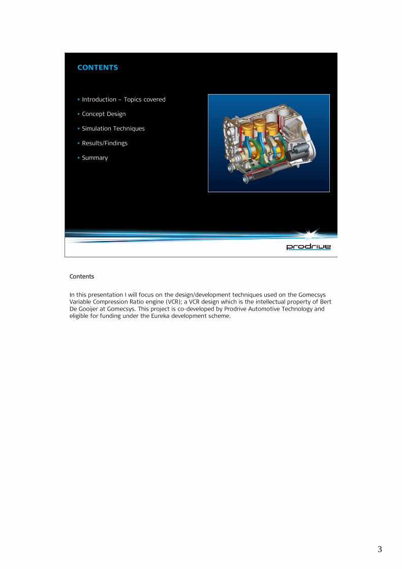
•Introduction –Topics covered
•Concept Design
•Simulation Techniques
•Results/Findings
•Summary
contents
Contents
In this presentation I will focus on the design/development techniques used on the GomecsysVariable Compression Ratio engine (VCR); a VCR design which is the intellectual property of BertDe Gooijer at Gomecsys. This project is co-developed by Prodrive Automotive Technology andeligible for funding under the Eureka development scheme.
4
introduction
Date to beremoved
Date to beremoved
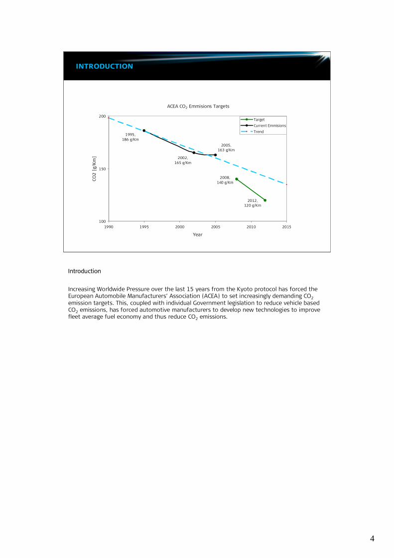
ACEA CO2 Emmisions Targets
2008,140 g/Km
2012,120 g/Km
2005,163 g/Km
2002,165 g/Km
1995,186 g/Km
100
150
200
1990 1995 2000 2005 2010 2015
Year
CO2
[g/K
m]
TargetCurrent EmmisionsTrend
Introduction
Increasing Worldwide Pressure over the last 15 years from the Kyoto protocol has forced theEuropean Automobile Manufacturers’Association (ACEA) to set increasingly demanding CO2emission targets. This, coupled with individual Government legislation to reduce vehicle basedCO2 emissions, has forced automotive manufacturers to develop new technologies to improvefleet average fuel economy and thus reduce CO2 emissions.
5
introduction
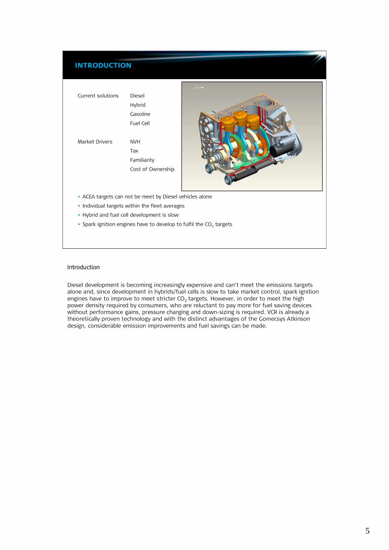
Current solutions Diesel
Hybrid
Gasoline
Fuel Cell
Market Drivers NVH
Tax
Familiarity
Cost of Ownership
•ACEA targets can not be meet by Diesel vehicles alone
•Individual targets within the fleet averages
•Hybrid and fuel cell development is slow
•Spark ignition engines have to develop to fulfil the CO2 targets Date to beremoved
Date to beremoved
Introduction
Diesel development is becoming increasingly expensive and can’t meet the emissions targetsalone and, since development in hybrids/fuel cells is slow to take market control, spark ignitionengines have to improve to meet stricter CO2 targets. However, in order to meet the highpower density required by consumers, who are reluctant to pay more for fuel saving deviceswithout performance gains, pressure charging and down-sizing is required. VCR is already atheoretically proven technology and with the distinct advantages of the Gomecsys Atkinsondesign, considerable emission improvements and fuel savings can be made.

6
overall concept
Date to beremoved
Date to beremoved
•Based on a 6mm eccentric on thecrankshaft pin
•Electronically actuated compression ratiochange from 6:1 to 15:1
•Complete 720°, 25% over expandedAtkinson cycle.
•30% reduced fuel consumption/CO2 outputwithout sacrificing full load power.
Fuel Conversion Efficiency
0
0.1
0.2
0.3
0.4
0.5
0.6
0.7
0.8
0 4 8 12 16 20 24 28
Compression Ratio
Con
vers
ion
Effi
cien
cy
Introduction –Design and concept
Prodrive believes that the prototype 4 cylinder Gomecsys engine will need to produce 100kWfrom 1.1L capacity to have a competitive role in the market place. VCR strategy allows balancebetween full load detonation control and part load thermal/fuel conversion efficiency. Thevariable compression ratio, over-expanded cycle, combined with pressure charging will meet theprogram targets of 30% fuel reduction over the European Union Drive Cycle compared to asimilar engine with the same power output.
7
concept design
Date to beremoved
Date to beremovedInternal Ring
GearEccentric
Effects of Worm Wheel angle on piston position
130
140
150
160
170
180
190
200
210
220
0 90 180 270 360 450 540 630 720
Crank Angle (Deg)
Pist
on
posi
tio
nfr
om
cran
ksha
ftce
ntre
(mm
)
0°
10°
20°
30°
40°
50°
60°
Combustion Stroke Exhaust Stroke Intake Stro ke Compression Stro ke
Over expandedpower strokedue to low
BDC
Low gas exchange increasesinternal EGR and elimates valve
pockets
AdvancedBDC with
Retarded BDCwith high
compression
Retarded TDC withlow compression
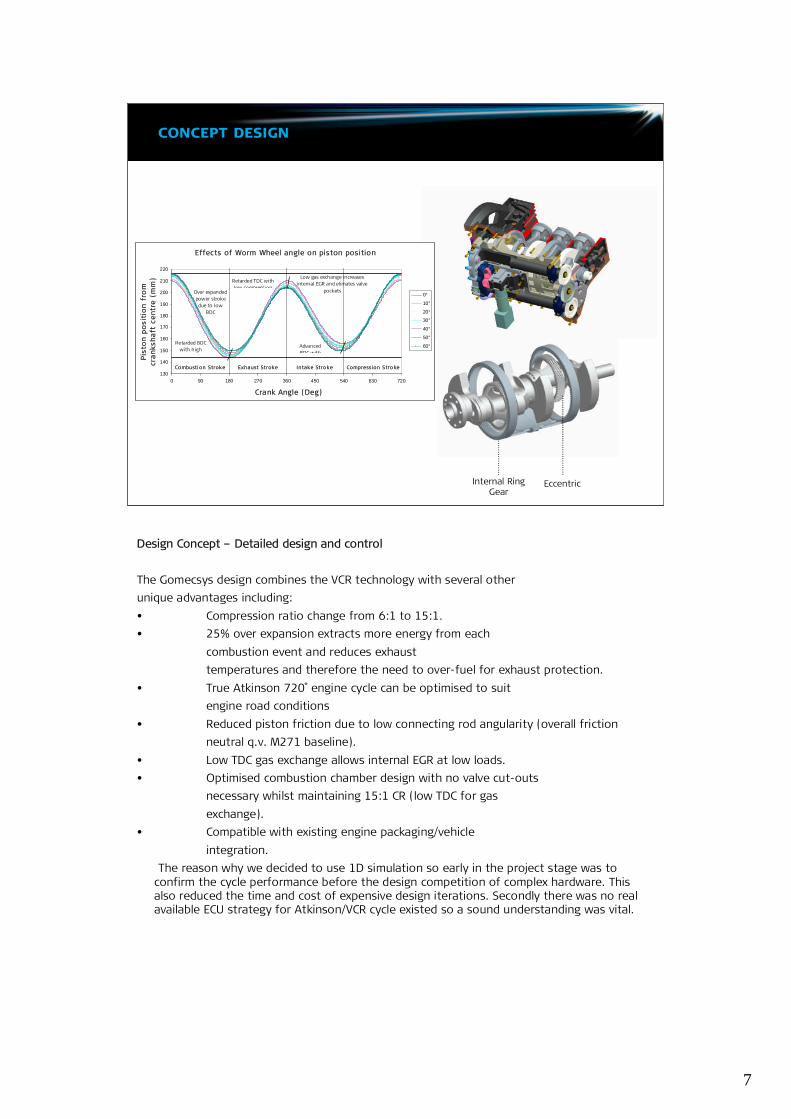
Design Concept –Detailed design and control
The Gomecsys design combines the VCR technology with several otherunique advantages including:• Compression ratio change from 6:1 to 15:1.• 25% over expansion extracts more energy from each
combustion event and reduces exhausttemperatures and therefore the need to over-fuel for exhaust protection.
• True Atkinson 720 e̊ngine cycle can be optimised to suitengine road conditions
• Reduced piston friction due to low connecting rod angularity (overall frictionneutral q.v. M271 baseline).
• Low TDC gas exchange allows internal EGR at low loads.• Optimised combustion chamber design with no valve cut-outs
necessary whilst maintaining 15:1 CR (low TDC for gasexchange).
• Compatible with existing engine packaging/vehicleintegration.
The reason why we decided to use 1D simulation so early in the project stage was toconfirm the cycle performance before the design competition of complex hardware. Thisalso reduced the time and cost of expensive design iterations. Secondly there was no realavailable ECU strategy for Atkinson/VCR cycle existed so a sound understanding was vital.

8
base engine
Date to beremoved
Date to beremoved
Mercedes M271
•Combustion system designed for similarairflow and power output
•Supercharger installation with activecontrol
•Extensive inlet system NVH development•Balance shaft installation•Dual cam phasing
•Build and correlate Mercedes M271 model using our combustion data base.•Update the correlation with test bed/real combustion data.•Modify the standard model with VCR “additions”•Correlate VCR piston motion with known curves and data from similar pressure
charged engines.•Target compression ratio optimisation using end of compression temperature.•Revisited simulation once VCR is running for final sign-off.
Simulation Plan
Base Engine
The Mercedes M271 was chosen for as the base/benchmark engine as it’s the leading marketexample of a lightly downsized pressure charged engine. The M271, which forms the basis forour simulation model, was initially calibrated against generic performance data.Later in the project phase, once the M271 was running with our in-house DP200 Micro Proteuscontrolled ECU, real test bed data was used to correlate the simulation model. The VCRadditions were overlaid to form a high confidence model which was used to increase ourknowledge of trends/interactions and to help in the development of the engine controlstrategy.
9
simulation m271 model
Date to beremoved
Date to beremoved
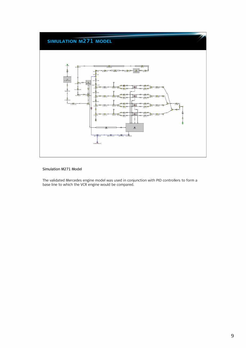
Simulation M271 Model
The validated Mercedes engine model was used in conjunction with PID controllers to form abase line to which the VCR engine would be compared.
10
validation m271 model
Date to beremoved
Date to beremoved
0
100
200
300
400
500
BSFC
[g/K
w-h
]
M271 SimulatedData Error
BSFC
5.76%
0200400600800
1000
Tem
pera
ture
(K)
M271 SimulatedData
Error
Exhaust Gas Temperature
2.37%
0
10
20
30
40
Pres
sure
[Bar
]
Dyno Data Simulated Data Error
EBP
0.21%
0
0.1
0.2
0.3
0.4
Effic
ienc
y[%
]
M271 Simulated Data Error
Volumetric Efficiency
0.87%
0
2.5
5
7.5
10
Pow
er[K
w]
M271 Simulated Data Error
Engine Power
0.53%
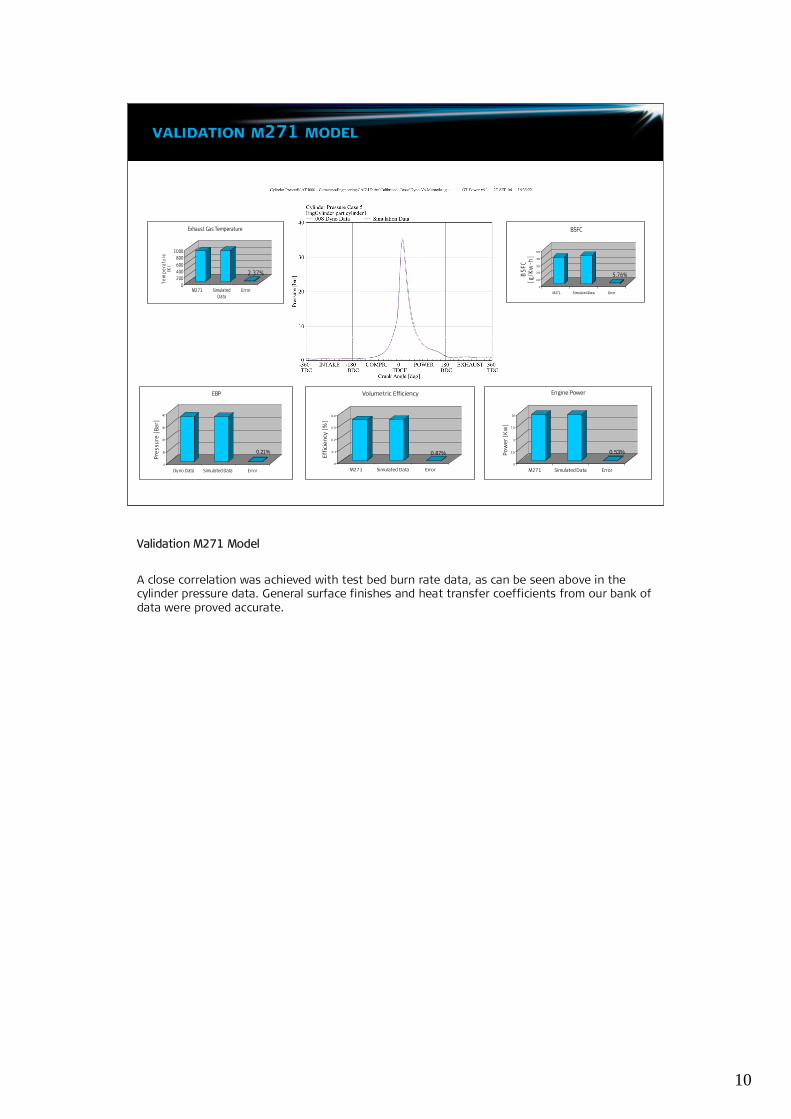
Validation M271 Model
A close correlation was achieved with test bed burn rate data, as can be seen above in thecylinder pressure data. General surface finishes and heat transfer coefficients from our bank ofdata were proved accurate.
11
simulation vcr model
Date to beremoved
Date to beremoved
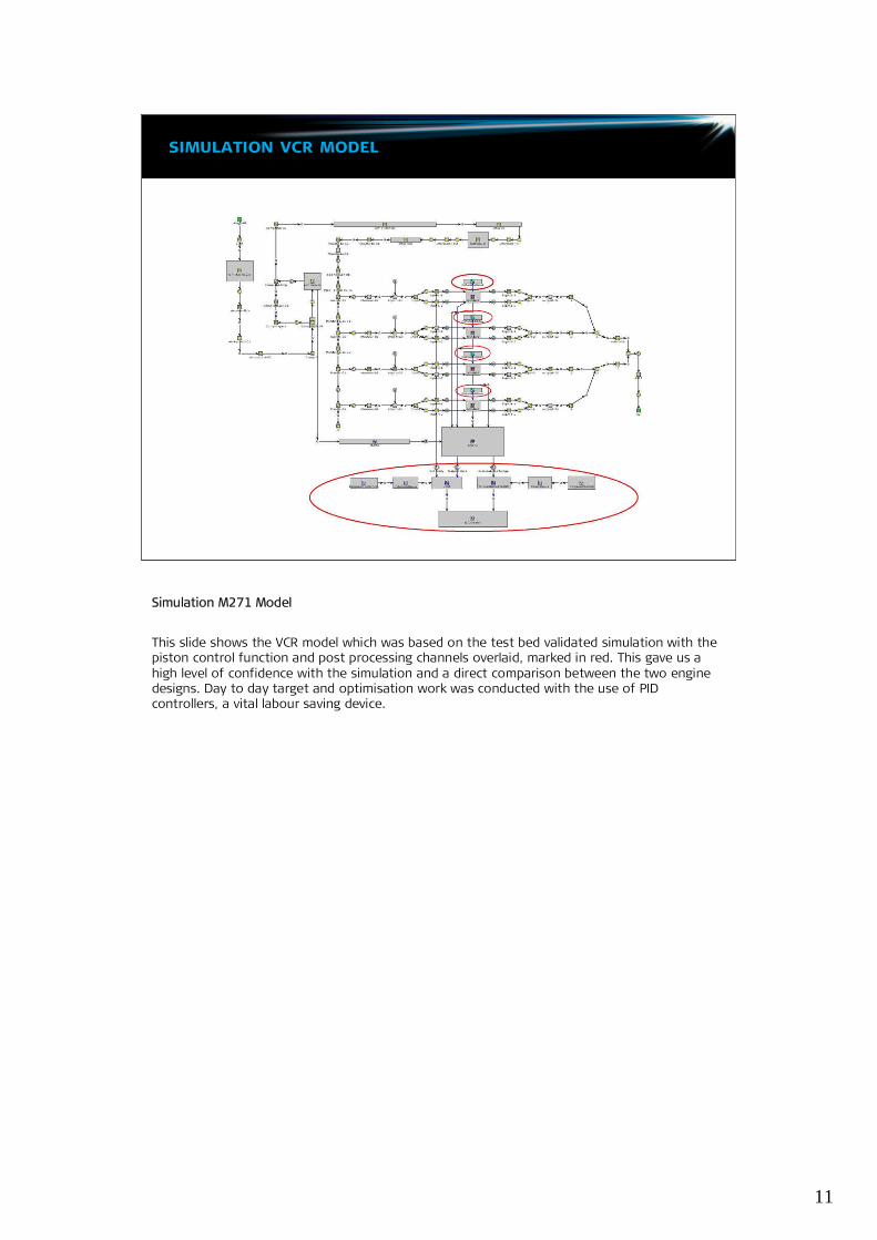
Simulation M271 Model
This slide shows the VCR model which was based on the test bed validated simulation with thepiston control function and post processing channels overlaid, marked in red. This gave us ahigh level of confidence with the simulation and a direct comparison between the two enginedesigns. Day to day target and optimisation work was conducted with the use of PIDcontrollers, a vital labour saving device.
12
piston motion
Date to beremoved
Date to beremoved
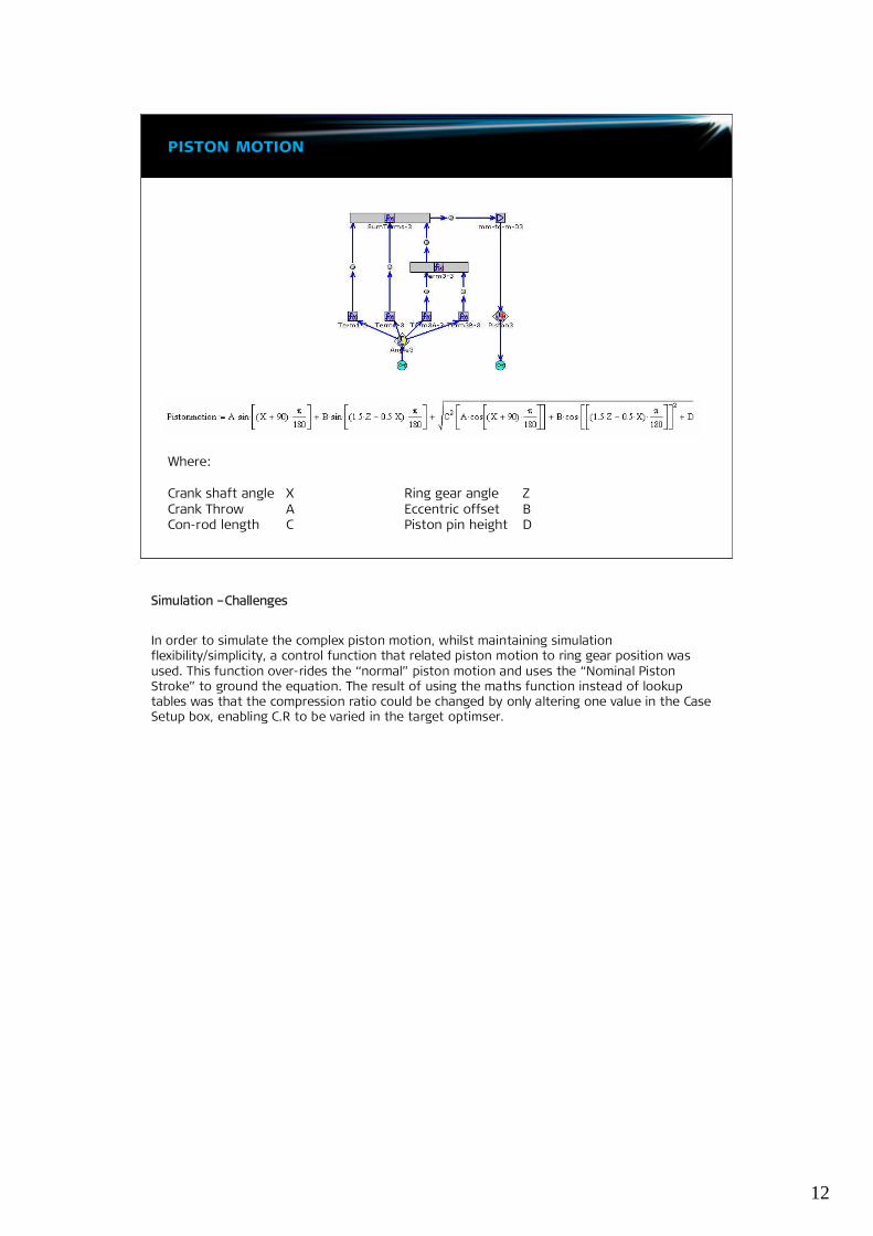
Where:
Crank shaft angle X Ring gear angle ZCrank Throw A Eccentric offset BCon-rod length C Piston pin height D
Simulation –Challenges
In order to simulate the complex piston motion, whilst maintaining simulationflexibility/simplicity, a control function that related piston motion to ring gear position wasused. This function over-rides the “normal”piston motion and uses the “Nominal PistonStroke”to ground the equation. The result of using the maths function instead of lookuptables was that the compression ratio could be changed by only altering one value in the CaseSetup box, enabling C.R to be varied in the target optimser.
13
post processing
Date to beremoved
Date to beremoved
Piston stroke and TDC clearances
-90.00
-80.00
-70.00
-60.00
-50.00
-40.00
-30.00
-20.00
-10.00
0.00
Dis
tanc
e[m
m]
Com
pres
sion
Com
bust
ion
Exha
ust
Inta
ke
Inta
ke
Com
pres
sion
Com
bust
ion
Exh
aust
Inta
ke
Com
pres
sion
Com
bust
ion
Exha
ust
C.R = 15:1C.R. =10.5:1C.R. = 6:1
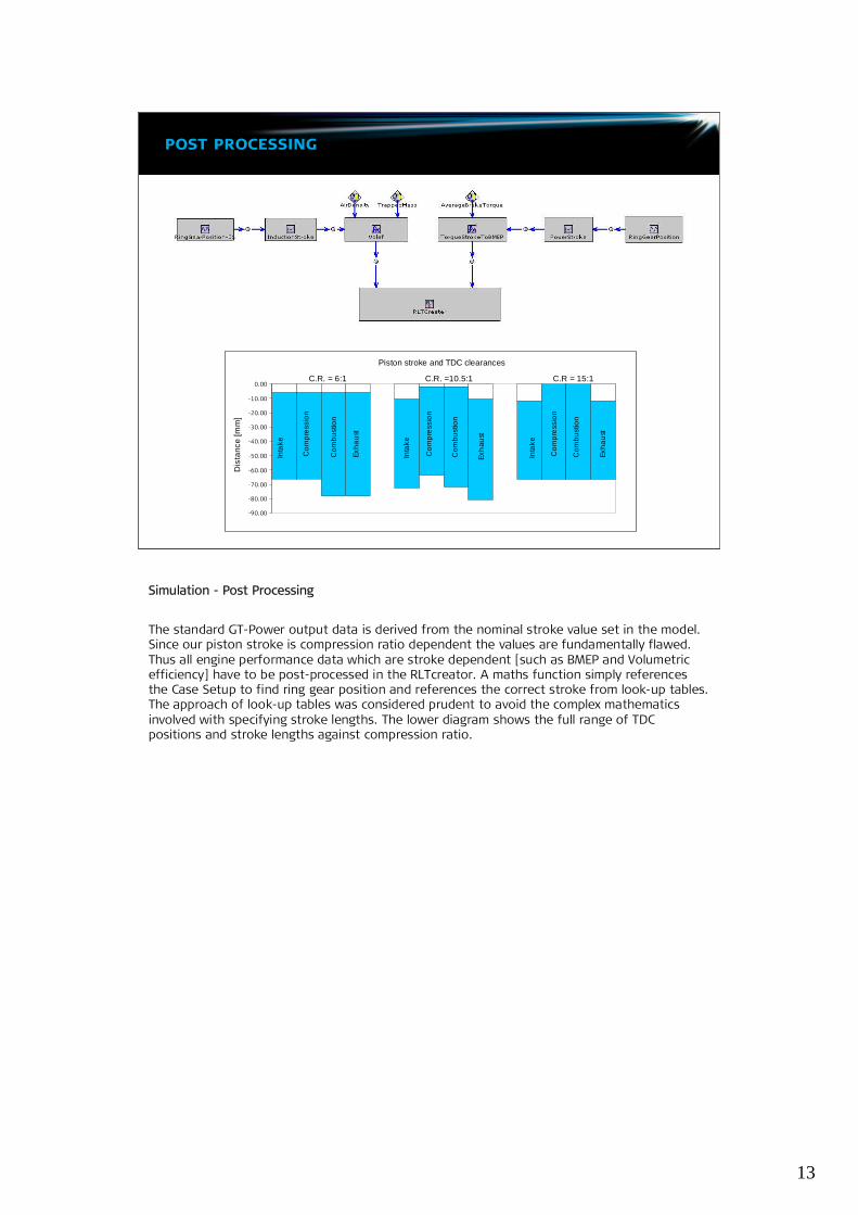
Simulation - Post Processing
The standard GT-Power output data is derived from the nominal stroke value set in the model.Since our piston stroke is compression ratio dependent the values are fundamentally flawed.Thus all engine performance data which are stroke dependent [such as BMEP and Volumetricefficiency] have to be post-processed in the RLTcreator. A maths function simply referencesthe Case Setup to find ring gear position and references the correct stroke from look-up tables.The approach of look-up tables was considered prudent to avoid the complex mathematicsinvolved with specifying stroke lengths. The lower diagram shows the full range of TDCpositions and stroke lengths against compression ratio.
14
engine sites
Date to beremoved
Date to beremoved
Chassis dynomometer operating cycle and extra-urban cycle
0
20
40
60
80
100
120
140
0 60 120 180 240 300 360 420 480 540 600
Time [sec]
Vehi
cle
spee
d[K
m/h
]
Mid urban
Top urban
Top extra urban
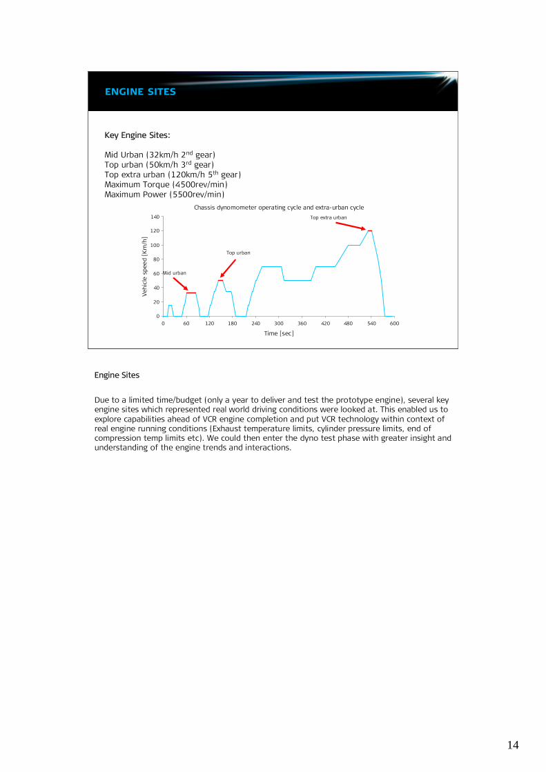
Key Engine Sites:
Mid Urban (32km/h 2nd gear)Top urban (50km/h 3rd gear)Top extra urban (120km/h 5th gear)Maximum Torque (4500rev/min)Maximum Power (5500rev/min)
Engine Sites
Due to a limited time/budget (only a year to deliver and test the prototype engine), several keyengine sites which represented real world driving conditions were looked at. This enabled us toexplore capabilities ahead of VCR engine completion and put VCR technology within context ofreal engine running conditions (Exhaust temperature limits, cylinder pressure limits, end ofcompression temp limits etc). We could then enter the dyno test phase with greater insight andunderstanding of the engine trends and interactions.

15
real world benefits –part throttle
Date to beremoved
Date to beremoved
Direct comparison between simulationat 9.55kW with bespoke strategycontrolled with DP200
0
100
200
300
400
500
BSFC
[g/k
W-h
]
M271 GomecsysVCR
Reduction
BSFC Reduction
25.6%
0
200
400
600
800
1000
Tem
pera
ture
[K]
M271 GomecsysVCR
Reduction
Exhaust Gas Temperature
7.41%
Real World Benefits
The benefit of increasing fuel conversion efficiency at part throttle is shown in this slide. Forexample when running at 14:1 instead of 9.3:1(at 2500rpm producing 9.55kW) the followingbenefits are shown.Currently, concessions have been made by using the basic combustion model and not exploringthe effects of EGR and VVT between the two engines. One can only conclude increasedsimulation accuracy and ultimate performance output can be achieved.

16
real world benefits - wot
900
1000
1100
1200
Tem
pera
ture
[K]
WOT Exhaust Temperatures
Mercedes WOT VCR WOT3000 4000 5000 5500
5%reduction
7%reduction
12%reduction
18%reduction
10
15
20
25
30
35
40
Brak
eEf
ficie
ncy
[%]
WOT Brake Efficiency
Mercedes WOT VCR WOT3000 4000 5000 5500
25%increase
20%increase
9%increase
3%increase
200
300
400
BSFC
[g/k
W-h
]
WOT BSFC
Mercedes WOT VCR WOT3000 4000 5000 5500
30%reduction
24%reduction
10%reduction
3%reduction
Direct comparison between simulationat WOT with bespoke strategycontrolled with DP200
10
12.5
15
AFR
Air Fuel Ratio
Mercedes WOT VCR WOT3000 4000 5000 5500
Real World Benefit
Since detonation is typically time consuming to model, a more practical approach was taken:test bed measured end of compression temperatures at Border Line Detonation (BLD) sitesprovided good indication of the cycle’s propensity to knock. This simple approach gave usconfidence that these load sites were close to BLD without the uncertainty of labour intensivecomplex combustion models.The over-expanded cycle lowers exhaust temperatures so fuel enrichment to protect theexhaust at higher loads can be reduced (i.e. move back toward LBT fuelling) until similarhardware limited temperatures as the M271 engine are achieved.
So now we have seen the benefits is summary……
17
summary/conclusion:
•Demonstrated our ability to deliver high performance engine programswithin tight dead lines.
•Increased confidence with investment.
•Allowed us to predict advantages of Gomecsysengine with a much reduced investment in time and money.
•Ultimately enabling quicker delivery of a more optimised VCR Atkinson cycleto vehicle demonstrator stage.
Future Development
•Continue VCR test bed development to confirm target performances.
•Develop VCR strategy to vehicle demonstrator level.
Summary/Conclusion
The strategy of using sound practical engine experience in hand with 1D simulation toolsdemonstrates our ability to deliver high performance engine programs to tight deadlines. Alongwith increased confidence in meeting performance targets and small budgets, the use of GT-Power was an extremely valuable tool.

18
creating cars consumers want
neverstop>>
Thank you for your time.