ethernet interface configuration
TRANSCRIPT
Operation Manual – Ethernet Interface (Access Volume) Table of Contents
i
Table of Contents
Chapter 1 Ethernet Interface Configuration ............................................................................... 1-1 1.1 Ethernet Interface Overview .............................................................................................. 1-1 1.2 General Ethernet Interface Configuration.......................................................................... 1-1
1.2.1 Combo Port Configuration....................................................................................... 1-2 1.2.2 Basic Ethernet Interface/Subinterface Configuration.............................................. 1-2 1.2.3 Configuring Flow Control on an Ethernet Interface................................................. 1-6 1.2.4 Configuring Loopback Testing on an Ethernet Interface......................................... 1-6 1.2.5 Configuring the Operating Mode of an Ethernet Interface ...................................... 1-7
1.3 Configuring a Layer 2 Ethernet Interface/Subinterface ..................................................... 1-8 1.3.1 Layer 2 Ethernet Interface/Subinterface Configuration Task List ........................... 1-8 1.3.2 Configuring Storm Suppression .............................................................................. 1-9 1.3.3 Configuring the MDI Mode for an Ethernet Interface ............................................ 1-12
1.4 Configuring a Layer 3 Ethernet Interface/Subinterface ................................................... 1-13 1.4.1 Layer 3 Ethernet Interface/Subinterface Configuration Task List ......................... 1-13 1.4.2 Setting the MTU for an Ethernet Interface/Subinterface....................................... 1-14 1.4.3 Configuring Link Layer State Change Suppression on an Ethernet Interface ...... 1-15
1.5 Displaying and Maintaining an Ethernet Interface/Subinterface...................................... 1-16
Operation Manual – Ethernet Interface (Access Volume) Chapter 1 Ethernet Interface Configuration
1-1
Chapter 1 Ethernet Interface Configuration
When configuring Ethernet interfaces, go to these sections for information you are interested in:
Ethernet Interface Overview General Ethernet Interface Configuration Configuring a Layer 2 Ethernet Interface/ Configuring a Layer 3 Ethernet Interface/ Displaying and Maintaining an Ethernet Interface/
1.1 Ethernet Interface Overview
Five types of Ethernet interfaces may be available on your device:
Layer 2 Ethernet interfaces. They are physical interfaces operating on the data link layer for forwarding Layer 2 protocol packets.
Layer 3 Ethernet interfaces. They are physical interfaces operating on the network layer for routing Layer 3 protocol packets. You can assign an IP address to a Layer 3 Ethernet interface.
Layer 2/Layer 3 Ethernet interfaces. They are physical interfaces that can operate on both the data link layer and the network layer. When operating on the data link layer, a Layer 2/Layer 3 Ethernet interface acts as a Layer 2 Ethernet interface; when operating on the network layer, a Layer 2/Layer 3 Ethernet interface acts as a Layer 3 Ethernet interface.
Layer 2 Ethernet subinterfaces. They are logical interfaces operating on the data link layer. They are mainly used for inter-VLAN packet forwarding on firewall cards. The link type of a Layer 2 Ethernet subinterface is access, which cannot be changed. You can add a Layer 2 subinterface to a VLAN in addition to performing the configurations described in this chapter on the subinterface. For the related configuration, refer to VLAN Configuration in the Access Volume. You may create Layer 2 Ethernet subinterfaces depending on the device.
Layer 3 Ethernet subinterfaces. They are logical interfaces operating on the network layer. You can assign an IP address to a Layer 3 Ethernet subinterface. A Layer 3 Ethernet subinterface only sends and receives packets for a particular VLAN. By creating subinterfaces on a Layer 3 Ethernet interface, you can enable the interface to carry packets for multiple VLANs.
1.2 General Ethernet Interface Configuration
This section describes the attributes and configurations common to Layer 2 and Layer 3 Ethernet interfaces. For specific attributes, refer to related sections hereinafter.
Operation Manual – Ethernet Interface (Access Volume) Chapter 1 Ethernet Interface Configuration
1-2
1.2.1 Combo Port Configuration
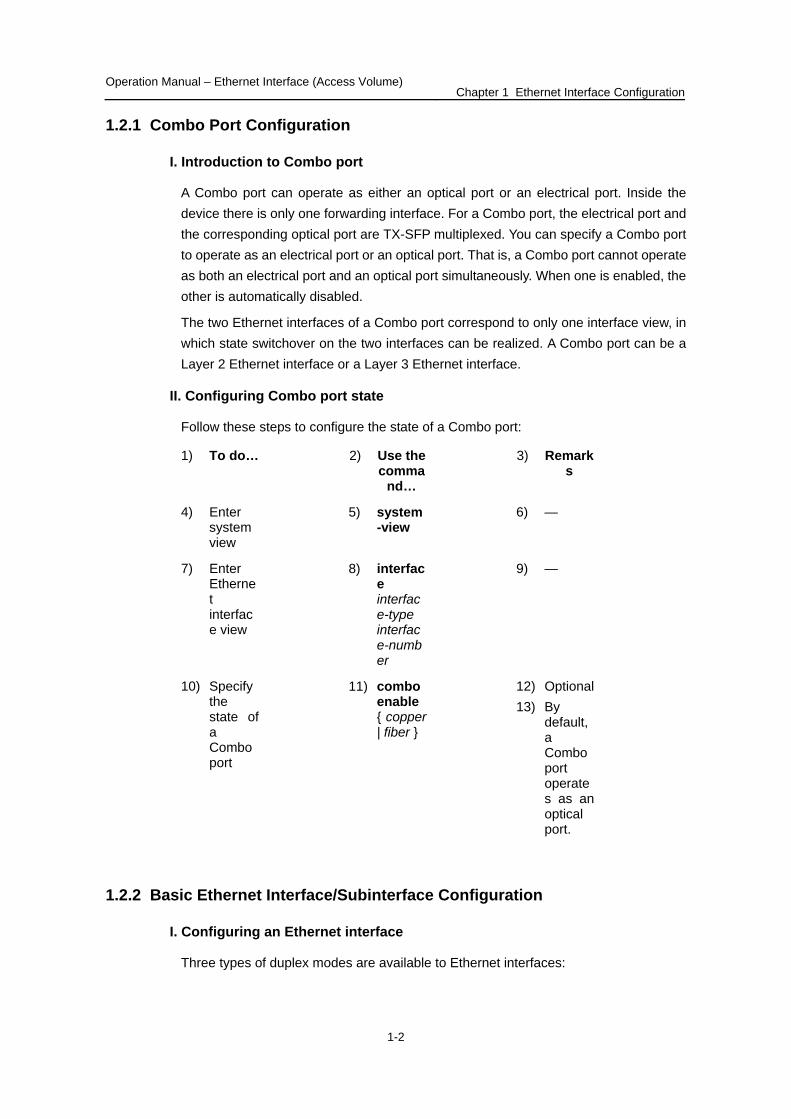
I. Introduction to Combo port
A Combo port can operate as either an optical port or an electrical port. Inside the device there is only one forwarding interface. For a Combo port, the electrical port and the corresponding optical port are TX-SFP multiplexed. You can specify a Combo port to operate as an electrical port or an optical port. That is, a Combo port cannot operate as both an electrical port and an optical port simultaneously. When one is enabled, the other is automatically disabled.
The two Ethernet interfaces of a Combo port correspond to only one interface view, in which state switchover on the two interfaces can be realized. A Combo port can be a Layer 2 Ethernet interface or a Layer 3 Ethernet interface.
II. Configuring Combo port state
Follow these steps to configure the state of a Combo port:
1) To do… 2) Use the comma
nd…
3) Remarks
4) Enter system view
5) system-view
6) —
7) Enter Ethernet interface view
8) interface interface-type interface-number
9) —
10) Specify the state of a Combo port
11) combo enable { copper | fiber }
12) Optional 13) By
default, a Combo port operates as an optical port.
1.2.2 Basic Ethernet Interface/Subinterface Configuration
I. Configuring an Ethernet interface
Three types of duplex modes are available to Ethernet interfaces:
Operation Manual – Ethernet Interface (Access Volume) Chapter 1 Ethernet Interface Configuration
1-3
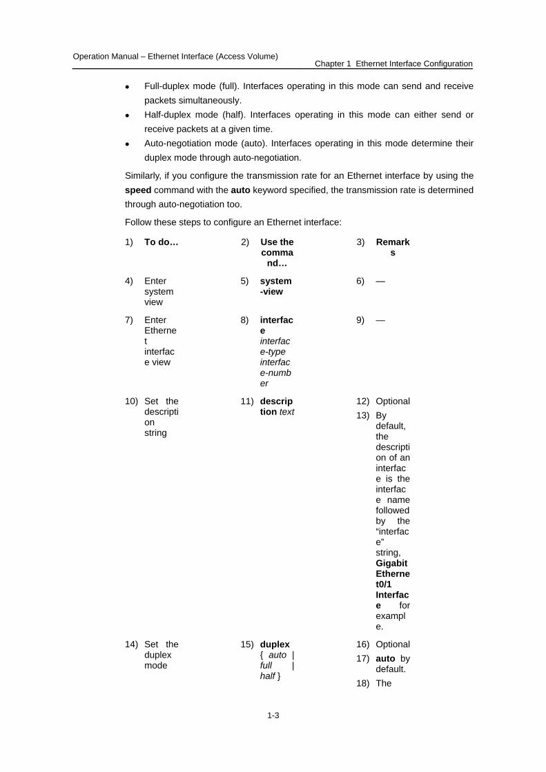
Full-duplex mode (full). Interfaces operating in this mode can send and receive packets simultaneously.
Half-duplex mode (half). Interfaces operating in this mode can either send or receive packets at a given time.
Auto-negotiation mode (auto). Interfaces operating in this mode determine their duplex mode through auto-negotiation.
Similarly, if you configure the transmission rate for an Ethernet interface by using the speed command with the auto keyword specified, the transmission rate is determined through auto-negotiation too.
Follow these steps to configure an Ethernet interface:
1) To do… 2) Use the comma
nd…
3) Remarks
4) Enter system view
5) system-view
6) —
7) Enter Ethernet interface view
8) interface interface-type interface-number
9) —
10) Set the description string
11) description text
12) Optional 13) By
default, the description of an interface is the interface name followed by the “interface” string, GigabitEthernet0/1 Interface for example.
14) Set the duplex mode
15) duplex { auto | full | half }
16) Optional 17) auto by
default. 18) The
Operation Manual – Ethernet Interface (Access Volume) Chapter 1 Ethernet Interface Configuration
1-4
2) Use the comma
nd…
1) To do… 3) Remarks
optical interface of a combo port does not support the half keyword.
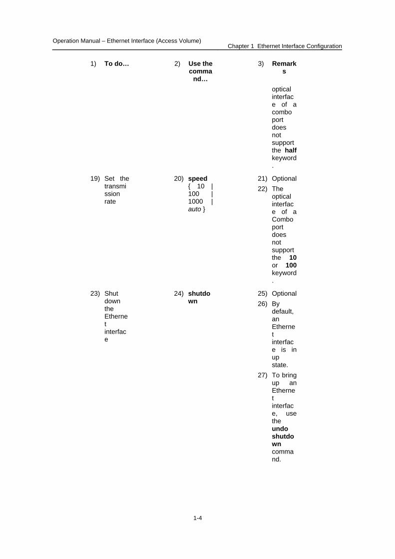
19) Set the transmission rate
20) speed { 10 | 100 | 1000 | auto }
21) Optional 22) The
optical interface of a Combo port does not support the 10 or 100 keyword.
23) Shut down the Ethernet interface
24) shutdown
25) Optional 26) By
default, an Ethernet interface is in up state.
27) To bring up an Ethernet interface, use the undo shutdown command.

Operation Manual – Ethernet Interface (Access Volume) Chapter 1 Ethernet Interface Configuration
1-5
II. Configuring an Ethernet subinterface
Follow these steps to configure an Ethernet subinterface:
1) To do… 2) Use the comma
nd…
3) Remarks
4) Enter system view
5) system-view
6) —
7) Create an Ethernet subinterface
8) interface interface-type interface-number.subnumber
9) Required
10) This command also leads you to Ethernet subinterface view.
11) Set the description string of the Ethernet subinterface
12) description text
13) Optional 14) By
default, the description string is “interface index + interface”. For example, GigabitEthernet0/1.1 Interface.
15) Shut down the Ethernet subinterface
16) shutdown
17) Optional 18) By
default, an Ethernet subinterface is in up state.
Operation Manual – Ethernet Interface (Access Volume) Chapter 1 Ethernet Interface Configuration
1-6
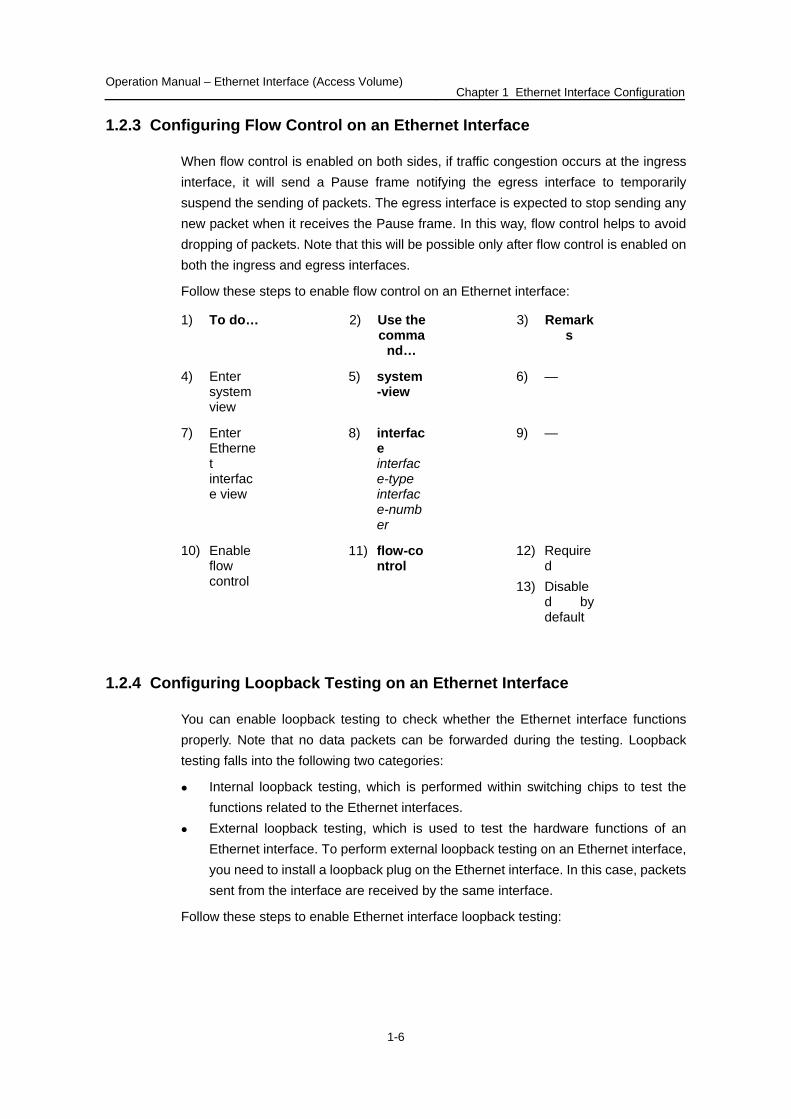
1.2.3 Configuring Flow Control on an Ethernet Interface
When flow control is enabled on both sides, if traffic congestion occurs at the ingress interface, it will send a Pause frame notifying the egress interface to temporarily suspend the sending of packets. The egress interface is expected to stop sending any new packet when it receives the Pause frame. In this way, flow control helps to avoid dropping of packets. Note that this will be possible only after flow control is enabled on both the ingress and egress interfaces.
Follow these steps to enable flow control on an Ethernet interface:
1) To do… 2) Use the comma
nd…
3) Remarks
4) Enter system view
5) system-view
6) —
7) Enter Ethernet interface view
8) interface interface-type interface-number
9) —
10) Enable flow control
11) flow-control
12) Required
13) Disabled by default
1.2.4 Configuring Loopback Testing on an Ethernet Interface
You can enable loopback testing to check whether the Ethernet interface functions properly. Note that no data packets can be forwarded during the testing. Loopback testing falls into the following two categories:
Internal loopback testing, which is performed within switching chips to test the functions related to the Ethernet interfaces.
External loopback testing, which is used to test the hardware functions of an Ethernet interface. To perform external loopback testing on an Ethernet interface, you need to install a loopback plug on the Ethernet interface. In this case, packets sent from the interface are received by the same interface.
Follow these steps to enable Ethernet interface loopback testing:
Operation Manual – Ethernet Interface (Access Volume) Chapter 1 Ethernet Interface Configuration
1-7
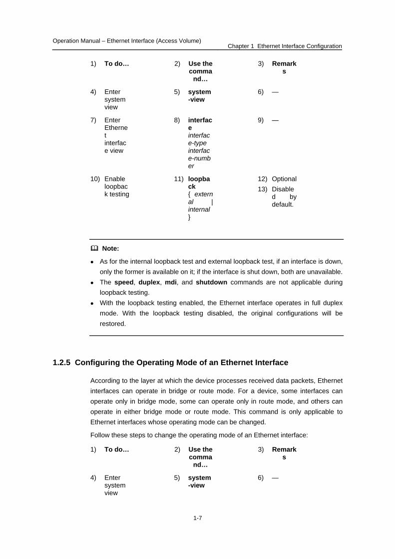
1) To do… 2) Use the comma
nd…
3) Remarks
4) Enter system view
5) system-view
6) —
7) Enter Ethernet interface view
8) interface interface-type interface-number
9) —
10) Enable loopback testing
11) loopback { external | internal }
12) Optional 13) Disable
d by default.
Note:
As for the internal loopback test and external loopback test, if an interface is down, only the former is available on it; if the interface is shut down, both are unavailable.
The speed, duplex, mdi, and shutdown commands are not applicable during loopback testing.
With the loopback testing enabled, the Ethernet interface operates in full duplex mode. With the loopback testing disabled, the original configurations will be restored.
1.2.5 Configuring the Operating Mode of an Ethernet Interface
According to the layer at which the device processes received data packets, Ethernet interfaces can operate in bridge or route mode. For a device, some interfaces can operate only in bridge mode, some can operate only in route mode, and others can operate in either bridge mode or route mode. This command is only applicable to Ethernet interfaces whose operating mode can be changed.
Follow these steps to change the operating mode of an Ethernet interface:
1) To do… 2) Use the comma
nd…
3) Remarks
4) Enter system view
5) system-view
6) —
Operation Manual – Ethernet Interface (Access Volume) Chapter 1 Ethernet Interface Configuration
1-8
2) Use the comma
nd…
1) To do… 3) Remarks
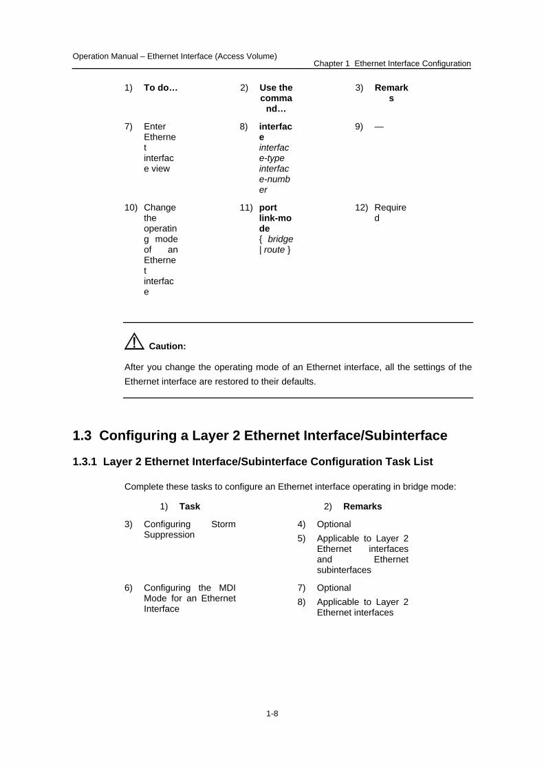
7) Enter Ethernet interface view
8) interface interface-type interface-number
9) —
10) Change the operating mode of an Ethernet interface
11) port link-mode { bridge | route }
12) Required
Caution:
After you change the operating mode of an Ethernet interface, all the settings of the Ethernet interface are restored to their defaults.
1.3 Configuring a Layer 2 Ethernet Interface/Subinterface
1.3.1 Layer 2 Ethernet Interface/Subinterface Configuration Task List
Complete these tasks to configure an Ethernet interface operating in bridge mode:
1) Task 2) Remarks
3) Configuring Storm Suppression
4) Optional 5) Applicable to Layer 2
Ethernet interfaces and Ethernet subinterfaces
6) Configuring the MDI Mode for an Ethernet Interface
7) Optional 8) Applicable to Layer 2
Ethernet interfaces
Operation Manual – Ethernet Interface (Access Volume) Chapter 1 Ethernet Interface Configuration
1-9
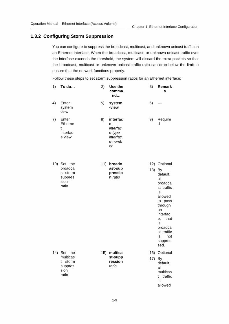
1.3.2 Configuring Storm Suppression
You can configure to suppress the broadcast, multicast, and unknown unicast traffic on an Ethernet interface. When the broadcast, multicast, or unknown unicast traffic over the interface exceeds the threshold, the system will discard the extra packets so that the broadcast, multicast or unknown unicast traffic ratio can drop below the limit to ensure that the network functions properly.
Follow these steps to set storm suppression ratios for an Ethernet interface:
1) To do… 2) Use the comma
nd…
3) Remarks
4) Enter system view
5) system-view
6) —
7) Enter Ethernet interface view
8) interface interface-type interface-number
9) Required
10) Set the broadcast storm suppression ratio
11) broadcast-suppression ratio
12) Optional 13) By
default, all broadcast traffic is allowed to pass through an interface, that is, broadcast traffic is not suppressed.
14) Set the multicast storm suppression ratio
15) multicast-suppression ratio
16) Optional 17) By
default, all multicast traffic is allowed

Operation Manual – Ethernet Interface (Access Volume) Chapter 1 Ethernet Interface Configuration
1-10
2) Use the comma
nd…
1) To do… 3) Remarks
to pass through an interface, that is, multicast traffic is not suppressed.
18) Set the unknown unicast storm suppression ratio
19) unicast-suppression ratio
20) Optional 21) By
default, all unknown unicast traffic is allowed to pass through an interface, that is, unknown unicast traffic is not suppressed.
Note:
If you set storm suppression ratios in Ethernet interface view or port group view repeatedly for an Ethernet interface that belongs to a port group, only the latest settings take effect.
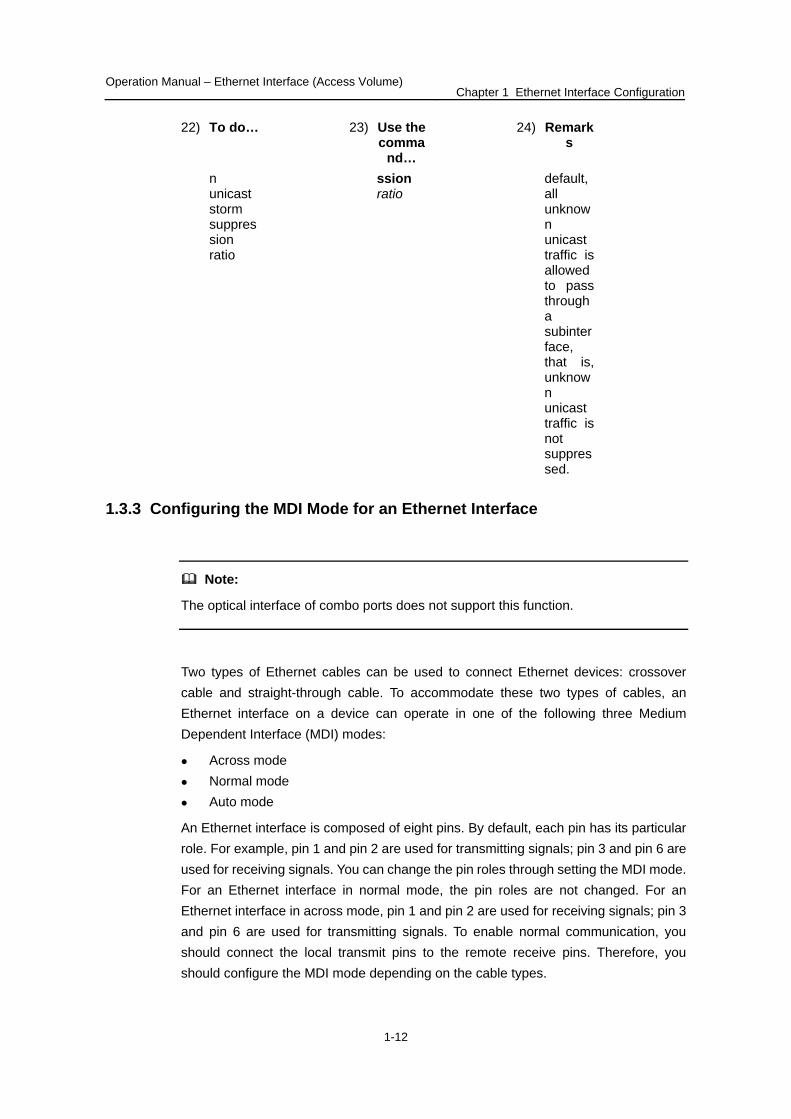
Follow these steps to set storm suppression ratios for an Ethernet subinterface:
22) To do… 23) Use the comma
nd…
24) Remarks
25) Enter system
26) system-view
27) —

Operation Manual – Ethernet Interface (Access Volume) Chapter 1 Ethernet Interface Configuration
1-11
23) Use the comma
nd…
22) To do… 24) Remarks
view
28) Enter Ethernet subinterface view
29) interface interface-type interface-number.subnumber
30) —
31) Set the broadcast storm suppression ratio
32) broadcast-suppression ratio
33) Optional 34) By
default, all broadcast traffic is allowed to pass through a subinterface, that is, broadcast traffic is not suppressed.
35) Set the multicast storm suppression ratio
36) multicast-suppression ratio
37) Optional 38) By
default, all multicast traffic is allowed to pass through a subinterface, that is, multicast traffic is not suppressed.
39) Set the unknow
40) unicast-suppre
41) Optional 42) By
Operation Manual – Ethernet Interface (Access Volume) Chapter 1 Ethernet Interface Configuration
1-12
23) Use the comma
nd…
22) To do… 24) Remarks
n unicast storm suppression ratio
ssion ratio
default, all unknown unicast traffic is allowed to pass through a subinterface, that is, unknown unicast traffic is not suppressed.
1.3.3 Configuring the MDI Mode for an Ethernet Interface
Note:
The optical interface of combo ports does not support this function.
Two types of Ethernet cables can be used to connect Ethernet devices: crossover cable and straight-through cable. To accommodate these two types of cables, an Ethernet interface on a device can operate in one of the following three Medium Dependent Interface (MDI) modes:
Across mode Normal mode Auto mode
An Ethernet interface is composed of eight pins. By default, each pin has its particular role. For example, pin 1 and pin 2 are used for transmitting signals; pin 3 and pin 6 are used for receiving signals. You can change the pin roles through setting the MDI mode. For an Ethernet interface in normal mode, the pin roles are not changed. For an Ethernet interface in across mode, pin 1 and pin 2 are used for receiving signals; pin 3 and pin 6 are used for transmitting signals. To enable normal communication, you should connect the local transmit pins to the remote receive pins. Therefore, you should configure the MDI mode depending on the cable types.
Operation Manual – Ethernet Interface (Access Volume) Chapter 1 Ethernet Interface Configuration
1-13
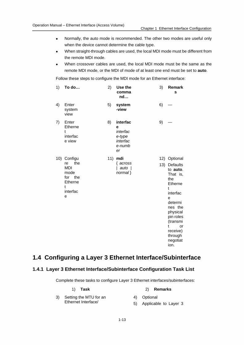
Normally, the auto mode is recommended. The other two modes are useful only when the device cannot determine the cable type.
When straight-through cables are used, the local MDI mode must be different from the remote MDI mode.
When crossover cables are used, the local MDI mode must be the same as the remote MDI mode, or the MDI of mode of at least one end must be set to auto.
Follow these steps to configure the MDI mode for an Ethernet interface:
1) To do… 2) Use the comma
nd…
3) Remarks
4) Enter system view
5) system-view
6) —
7) Enter Ethernet interface view
8) interface interface-type interface-number
9) —
10) Configure the MDI mode for the Ethernet interface
11) mdi { across | auto | normal }
12) Optional 13) Defaults
to auto. That is, the Ethernet interface determines the physical pin roles (transmit or receive) through negotiation.
1.4 Configuring a Layer 3 Ethernet Interface/Subinterface
1.4.1 Layer 3 Ethernet Interface/Subinterface Configuration Task List
Complete these tasks to configure Layer 3 Ethernet interfaces/subinterfaces:
1) Task 2) Remarks
3) Setting the MTU for an Ethernet Interface/
4) Optional 5) Applicable to Layer 3
Operation Manual – Ethernet Interface (Access Volume) Chapter 1 Ethernet Interface Configuration
1-14
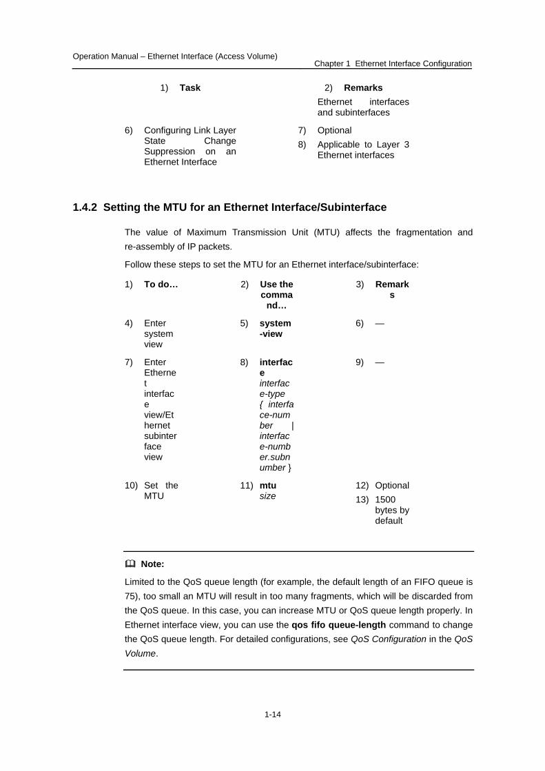
1) Task 2) Remarks Ethernet interfaces and subinterfaces
6) Configuring Link Layer State Change Suppression on an Ethernet Interface
7) Optional 8) Applicable to Layer 3
Ethernet interfaces
1.4.2 Setting the MTU for an Ethernet Interface/Subinterface
The value of Maximum Transmission Unit (MTU) affects the fragmentation and re-assembly of IP packets.
Follow these steps to set the MTU for an Ethernet interface/subinterface:
1) To do… 2) Use the comma
nd…
3) Remarks
4) Enter system view
5) system-view
6) —
7) Enter Ethernet interface view/Ethernet subinterface view
8) interface interface-type { interface-number | interface-number.subnumber }
9) —
10) Set the MTU
11) mtu size
12) Optional 13) 1500
bytes by default
Note:
Limited to the QoS queue length (for example, the default length of an FIFO queue is 75), too small an MTU will result in too many fragments, which will be discarded from the QoS queue. In this case, you can increase MTU or QoS queue length properly. In Ethernet interface view, you can use the qos fifo queue-length command to change the QoS queue length. For detailed configurations, see QoS Configuration in the QoS Volume.
Operation Manual – Ethernet Interface (Access Volume) Chapter 1 Ethernet Interface Configuration
1-15
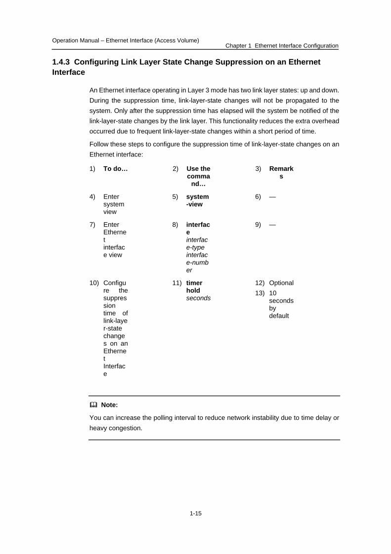
1.4.3 Configuring Link Layer State Change Suppression on an Ethernet Interface
An Ethernet interface operating in Layer 3 mode has two link layer states: up and down. During the suppression time, link-layer-state changes will not be propagated to the system. Only after the suppression time has elapsed will the system be notified of the link-layer-state changes by the link layer. This functionality reduces the extra overhead occurred due to frequent link-layer-state changes within a short period of time.
Follow these steps to configure the suppression time of link-layer-state changes on an Ethernet interface:
1) To do… 2) Use the comma
nd…
3) Remarks
4) Enter system view
5) system-view
6) —
7) Enter Ethernet interface view
8) interface interface-type interface-number
9) —
10) Configure the suppression time of link-layer-state changes on an Ethernet Interface
11) timer hold seconds
12) Optional 13) 10
seconds by default
Note:
You can increase the polling interval to reduce network instability due to time delay or heavy congestion.
Operation Manual – Ethernet Interface (Access Volume) Chapter 1 Ethernet Interface Configuration
1-16
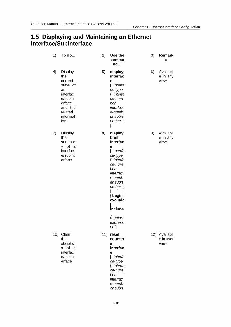
1.5 Displaying and Maintaining an Ethernet Interface/Subinterface
1) To do… 2) Use the comma
nd…
3) Remarks
4) Display the current state of an interface/subinterface and the related information
5) display interface [ interface-type [ interface-number | interface-number.subnumber ] ]
6) Available in any view
7) Display the summary of a interface/subinterface
8) display brief interface [ interface-type [ interface-number | interface-number.subnumber ] ] [ | { begin | exclude | include } regular-expression ]
9) Available in any view
10) Clear the statistics of a interface/subinterface
11) reset counters interface [ interface-type [ interface-number | interface-number.subn
12) Available in user view

Operation Manual – Ethernet Interface (Access Volume) Chapter 1 Ethernet Interface Configuration
1-17
2) Use the comma
nd…
1) To do… 3) Remarks
umber ] ]
13) Display the current ports that are of a specified type
14) display port { hybrid | trunk }
15) Available in any view
Operation Manual – Logical Interface (Access Volume) Table of Contents
Table of Contents
Chapter 1 Logical Interface Configuration ................................................................................. 1-1 1.1 Logical Interface Overview ................................................................................................ 1-1 1.2 Loopback Interface ............................................................................................................ 1-1
1.2.1 Introduction to Loopback Interface.......................................................................... 1-1 1.2.2 Configuring a Loopback Interface ........................................................................... 1-2
1.3 Null Interface...................................................................................................................... 1-2 1.3.1 Introduction to Null Interface ................................................................................... 1-2 1.3.2 Configuring a Null Interface..................................................................................... 1-3
1.4 Subinterface....................................................................................................................... 1-3 1.4.1 Introduction to Subinterface .................................................................................... 1-3 1.4.2 Configuring an Ethernet Subinterface..................................................................... 1-3 1.4.3 Ethernet Subinterface Configuration Example........................................................ 1-5
i
Operation Manual – Logical Interface (Access Volume) Chapter 1 Logical Interface Configuration
1-1
Chapter 1 Logical Interface Configuration
When configuring logical interfaces, go to these sections for information you are interested in:
Logical Interface Overview Loopback Interface Null Interface 错误!未找到引用源。Subinterface错误!未找到引用源。
Note:
This chapter only describes the basic configurations of logical interfaces. For the configuration of the data link layer, network layer, and special features, refer to the relevant features in the Access Volume and the IP Services Volume.
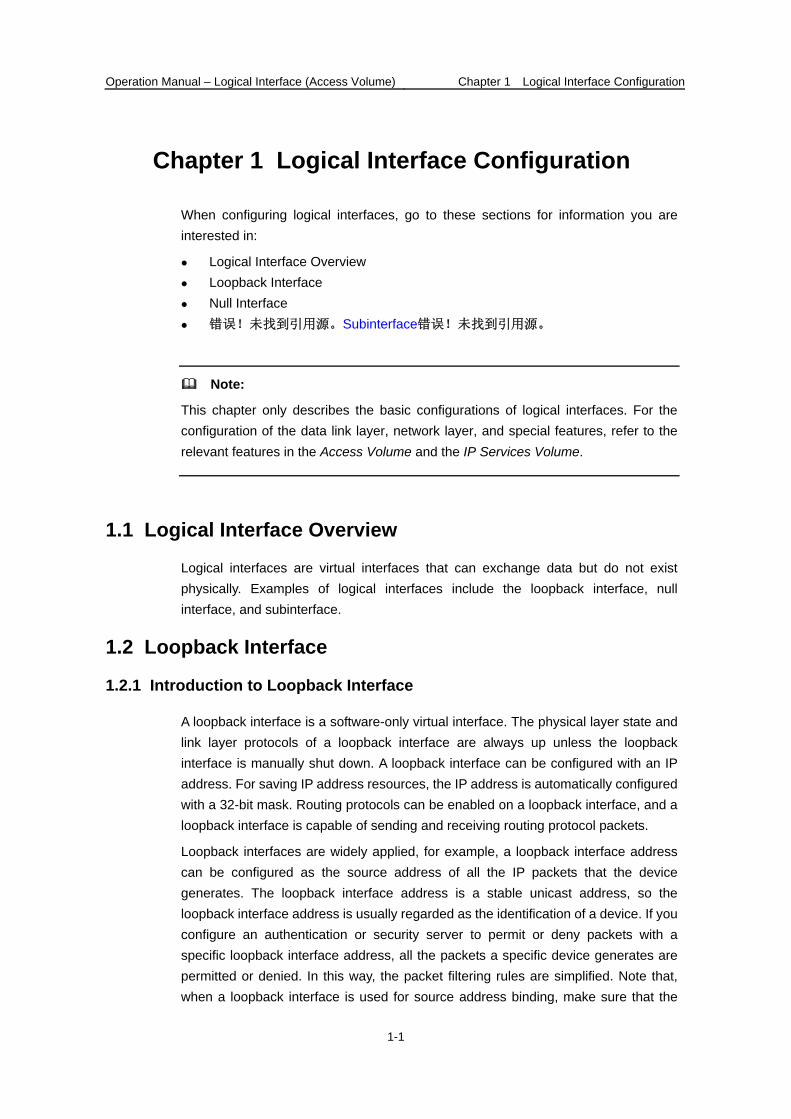
1.1 Logical Interface Overview
Logical interfaces are virtual interfaces that can exchange data but do not exist physically. Examples of logical interfaces include the loopback interface, null interface, and subinterface.
1.2 Loopback Interface
1.2.1 Introduction to Loopback Interface
A loopback interface is a software-only virtual interface. The physical layer state and link layer protocols of a loopback interface are always up unless the loopback interface is manually shut down. A loopback interface can be configured with an IP address. For saving IP address resources, the IP address is automatically configured with a 32-bit mask. Routing protocols can be enabled on a loopback interface, and a loopback interface is capable of sending and receiving routing protocol packets.
Loopback interfaces are widely applied, for example, a loopback interface address can be configured as the source address of all the IP packets that the device generates. The loopback interface address is a stable unicast address, so the loopback interface address is usually regarded as the identification of a device. If you configure an authentication or security server to permit or deny packets with a specific loopback interface address, all the packets a specific device generates are permitted or denied. In this way, the packet filtering rules are simplified. Note that, when a loopback interface is used for source address binding, make sure that the
Operation Manual – Logical Interface (Access Volume) Chapter 1 Logical Interface Configuration
1-2
route from the loopback interface to the peer is reachable; all data packets sent to the loopback interface are considered as packets sent to the device itself, so the device does not forward these packets.
Because a loopback interface is always up, it can be used for some special purposes. For example, if a router ID is not configured for a dynamic routing protocol, the highest loopback interface address is selected as the router ID.
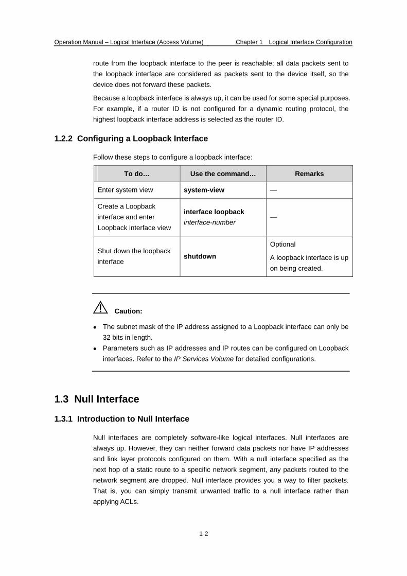
1.2.2 Configuring a Loopback Interface
Follow these steps to configure a loopback interface:
To do… Use the command… Remarks
Enter system view system-view —
Create a Loopback interface and enter Loopback interface view
interface loopback interface-number
—
Shut down the loopback interface
shutdown
Optional
A loopback interface is up on being created.
Caution:
The subnet mask of the IP address assigned to a Loopback interface can only be 32 bits in length.
Parameters such as IP addresses and IP routes can be configured on Loopback interfaces. Refer to the IP Services Volume for detailed configurations.
1.3 Null Interface
1.3.1 Introduction to Null Interface
Null interfaces are completely software-like logical interfaces. Null interfaces are always up. However, they can neither forward data packets nor have IP addresses and link layer protocols configured on them. With a null interface specified as the next hop of a static route to a specific network segment, any packets routed to the network segment are dropped. Null interface provides you a way to filter packets. That is, you can simply transmit unwanted traffic to a null interface rather than applying ACLs.
Operation Manual – Logical Interface (Access Volume) Chapter 1 Logical Interface Configuration
1-3
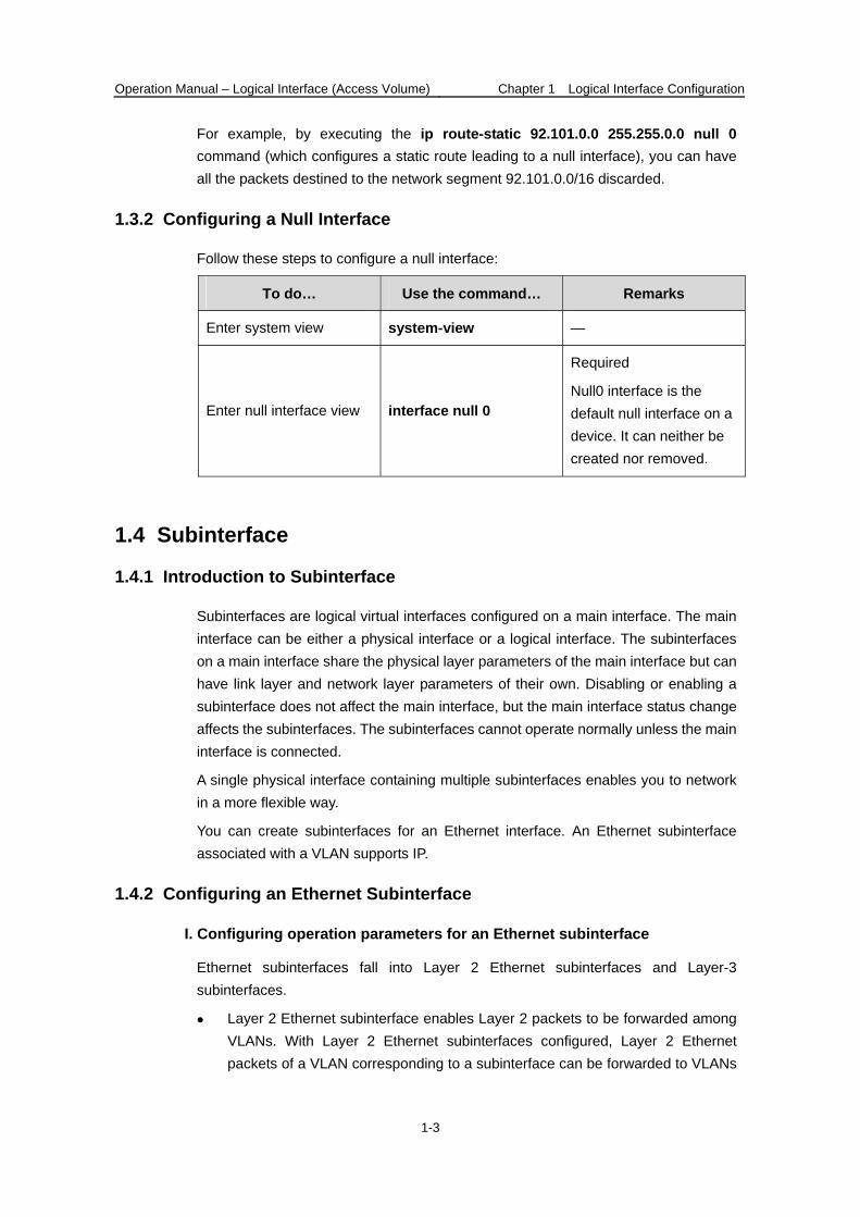
For example, by executing the ip route-static 92.101.0.0 255.255.0.0 null 0 command (which configures a static route leading to a null interface), you can have all the packets destined to the network segment 92.101.0.0/16 discarded.
1.3.2 Configuring a Null Interface
Follow these steps to configure a null interface:
To do… Use the command… Remarks
Enter system view system-view —
Enter null interface view interface null 0
Required
Null0 interface is the default null interface on a device. It can neither be created nor removed.
1.4 Subinterface
1.4.1 Introduction to Subinterface
Subinterfaces are logical virtual interfaces configured on a main interface. The main interface can be either a physical interface or a logical interface. The subinterfaces on a main interface share the physical layer parameters of the main interface but can have link layer and network layer parameters of their own. Disabling or enabling a subinterface does not affect the main interface, but the main interface status change affects the subinterfaces. The subinterfaces cannot operate normally unless the main interface is connected.
A single physical interface containing multiple subinterfaces enables you to network in a more flexible way.
You can create subinterfaces for an Ethernet interface. An Ethernet subinterface associated with a VLAN supports IP.
1.4.2 Configuring an Ethernet Subinterface
I. Configuring operation parameters for an Ethernet subinterface
Ethernet subinterfaces fall into Layer 2 Ethernet subinterfaces and Layer-3 subinterfaces.
Layer 2 Ethernet subinterface enables Layer 2 packets to be forwarded among VLANs. With Layer 2 Ethernet subinterfaces configured, Layer 2 Ethernet packets of a VLAN corresponding to a subinterface can be forwarded to VLANs
Operation Manual – Logical Interface (Access Volume) Chapter 1 Logical Interface Configuration
1-4
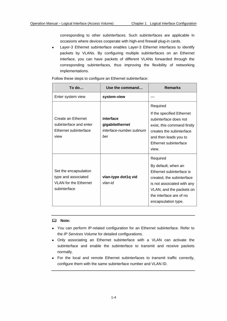
corresponding to other subinterfaces. Such subinterfaces are applicable in occasions where devices cooperate with high-end firewall plug-in cards.
Layer-3 Ethernet subinterface enables Layer-3 Ethernet interfaces to identify packets by VLANs. By configuring multiple subinterfaces on an Ethernet interface, you can have packets of different VLANs forwarded through the corresponding subinterfaces, thus improving the flexibility of networking implementations.
Follow these steps to configure an Ethernet subinterface:
To do… Use the command… Remarks
Enter system view system-view —
Create an Ethernet subinterface and enter Ethernet subinterface view
interface gigabitethernet interface-number.subnumber
Required
If the specified Ethernet subinterface does not exist, this command firstly creates the subinterface and then leads you to Ethernet subinterface view.
Set the encapsulation type and associated VLAN for the Ethernet subinterface
vlan-type dot1q vid vlan-id
Required
By default, when an Ethernet subinterface is created, the subinterface is not associated with any VLAN, and the packets on the interface are of no encapsulation type.
Note:
You can perform IP-related configuration for an Ethernet subinterface. Refer to the IP Services Volume for detailed configurations.
Only associating an Ethernet subinterface with a VLAN can activate the subinterface and enable the subinterface to transmit and receive packets normally.
For the local and remote Ethernet subinterfaces to transmit traffic correctly, configure them with the same subinterface number and VLAN ID.
Operation Manual – Logical Interface (Access Volume) Chapter 1 Logical Interface Configuration
1-5
II. Display and maintain Ethernet subinterfaces
After the above configuration, you can use the display command in any view to view the configuration information of the Ethernet subinterface, so as to verify the configuration.
Follow these steps to display and maintain Ethernet subinterfaces:
To do… Use the command…
Display the information about a subinterface
display interface interface-type interface-number.subnumber
Display the information about the VLAN of a subinterface
display vlan interface interface-type interface-number.subnumber
1.4.3 Ethernet Subinterface Configuration Example
I. Network requirements
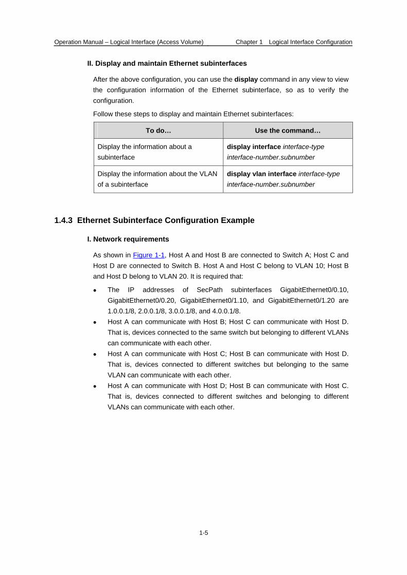
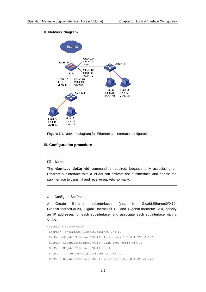
As shown in Figure 1-1, Host A and Host B are connected to Switch A; Host C and Host D are connected to Switch B. Host A and Host C belong to VLAN 10; Host B and Host D belong to VLAN 20. It is required that:
The IP addresses of SecPath subinterfaces GigabitEthernet0/0.10, GigabitEthernet0/0.20, GigabitEthernet0/1.10, and GigabitEthernet0/1.20 are 1.0.0.1/8, 2.0.0.1/8, 3.0.0.1/8, and 4.0.0.1/8.
Host A can communicate with Host B; Host C can communicate with Host D. That is, devices connected to the same switch but belonging to different VLANs can communicate with each other.
Host A can communicate with Host C; Host B can communicate with Host D. That is, devices connected to different switches but belonging to the same VLAN can communicate with each other.
Host A can communicate with Host D; Host B can communicate with Host C. That is, devices connected to different switches and belonging to different VLANs can communicate with each other.
Operation Manual – Logical Interface (Access Volume) Chapter 1 Logical Interface Configuration
1-6
II. Network diagram
Figure 1-1 Network diagram for Ethernet subinterface configuration
III. Configuration procedure
Note:
The vlan-type dot1q vid command is required, because only associating an Ethernet subinterface with a VLAN can activate the subinterface and enable the subinterface to transmit and receive packets normally.
Configure SecPath
# Create Ethernet subinterfaces (that is, GigabitEthernet0/0.10, GigabitEthernet0/0.20, GigabitEthernet0/1.10, and GigabitEthernet0/1.20), specify an IP addresses for each subinterface, and associate each subinterface with a VLAN.
<SecPath> system-view
[SecPath] interface GigabitEthernet 0/0.10
[SecPath-GigabitEthernet0/0.10] ip address 1.0.0.1 255.0.0.0
[SecPath-GigabitEthernet0/0.10] vlan-type dot1q vid 10
[SecPath-GigabitEthernet0/0.10] quit
[SecPath] interface GigabitEthernet 0/0.20
[SecPath-GigabitEthernet0/0.20] ip address 2.0.0.1 255.0.0.0

Operation Manual – Logical Interface (Access Volume) Chapter 1 Logical Interface Configuration
1-7
[SecPath-GigabitEthernet0/0.20] vlan-type dot1q vid 20
[SecPath-GigabitEthernet0/0.20] quit
[SecPath] interface GigabitEthernet 0/1.10
[SecPath-GigabitEthernet0/1.10] ip address 3.0.0.1 255.0.0.0
[SecPath-GigabitEthernet0/1.10] vlan-type dot1q vid 10
[SecPath-GigabitEthernet0/1.10] quit
[SecPath] interface GigabitEthernet 0/1.20
[SecPath-GigabitEthernet0/1.20] ip address 4.0.0.1 255.0.0.0
[SecPath-GigabitEthernet0/1.20] vlan-type dot1q vid 20
[SecPath-GigabitEthernet0/1.20] quit