estimating the overall damping ratio in structures with ... · estimating the overall damping ratio...
TRANSCRIPT
Estimating the overall damping ratio in structures with
brace–damper systems Blank line 11 pt Blank line 11 pt J. M. Londoño, D.J. Wagg & S.A. Neild Department of Mechanical Engineering. University of Bristol. Bristol, United Kingdom.
Blank line 11 pt Blank line 11 pt SUMMARY: Viscous fluid dampers have successfully been incorporated in a number of buildings proving to be effective to suppress unwanted vibrations in civil engineering structures. Even so, their application in standard seismic design solutions is not common. This is possibly owing to the lack of simple design guidelines for the dampers sizing, since most of the available design procedures are based on iterative approaches or sophisticated constrained optimisation problems. In this paper, we present a methodology for estimating the overall damping ratio of structures with added viscous fluid dampers. We take into account the effects of the supporting brace stiffness through the viscoelastic Maxwell model. Based on the study of single–degree–of–freedom structure under ground excitation, we proposed some semi–analytical expressions that could be useful for developing an easy–to–use design methodology for structures with supplemental damping systems. The proposed expressions have shown to be accurate enough, with estimation errors of about 0.5%, for describing the relationship between the system’s overall damping ratio and the brace/damper sizes in the region where the brace–damper interaction reduces the damper effectiveness. Blank line 10 pt Keywords: Supplemental damping, Viscoelastic Maxwell model, Viscous fluid damper design. Blank line 11 pt Blank line 11 pt 1. INTRODUTION Blank line 11 pt Typical systems for reducing unwanted vibrations in civil engineering structures comprise one of the three fundamental classes of (i) passive, (ii) semi-active, and (iii) active damping devices (See Dyke (2005)). Different types of dampers have been made available for years in which variety of materials have been used to obtain various levels of stiffness and damping. These include: viscous fluid, viscoelastic, friction, metallic yield and magnetorheological dampers, which have different dynamic characteristics so as to affect the responses of the damper–added structures differently as it can be seen in Hanson & Soong (2001); Spencer & Nagarajaiah (2003) and Miyamoto & Hanson (2004) among others. In this paper, we consider passive systems based on linear viscous fluid dampers. A well–designed system based on viscous fluid damper could effectively mitigate the hazard posed by the strong dynamic forces as those generated by wind or seismic loads. In recent years much research has been aimed at reliable and cost–effective design methodologies. Most of the solutions are based on trial–and–error approaches, iterative procedures or constrained optimisation problems. For instance, two optimal design methodologies for passive dampers based on active control theories are presented in Yang et al. (2002). The authors claim the methodologies are capable of determining the optimal locations and the corresponding sizes of the dampers. Similarly, in Ribakov & Reinhorn (2003) an optimal design procedure is proposed to obtain the initial properties of the viscous dampers. This aims to reduce the structural seismic responses and is based on the linear quadratic regulator (LQR) technique. In Lavan & Levy (2006) and Lavan & Levy (2005) a methodology for the optimal design of viscous dampers is also presented. They both assumed linear structural behaviour and addressed the problem of minimising the added damping but differ in what constraint it is subjected to; the storey drift in one case and the energy global damage index in the second case. In a similar way Agranovich
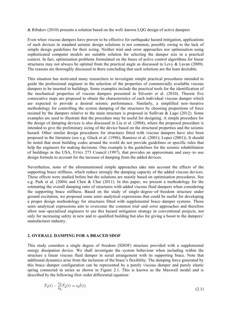
& Ribakov (2010) presents a solution based on the well–known LQG design of active dampers Even when viscous dampers have proven to be effective for earthquake hazard mitigation, applications of such devices in standard seismic design solutions is not common, possibly owing to the lack of simple design guidelines for their sizing. Neither trial–and–error approaches nor optimisation using sophisticated computer models are suitable solution for selecting the damper size in a practical context. In fact, optimisation problems formulated on the bases of active control algorithms for linear structures may not always be optimal from the practical angle as discussed in Levy & Lavan (2009). The reasons are thoroughly discussed in there concluding that such solutions are the least desirable. This situation has motivated many researchers to investigate simple practical procedures intended to guide the professional engineer in the selection of the properties of commercially available viscous dampers to be inserted in buildings. Some examples include the practical tools for the identification of the mechanical properties of viscous dampers presented in Silvestri et al. (2010). Therein five consecutive steps are proposed to obtain the characteristics of each individual viscous damper which are expected to provide a desired seismic performance. Similarly, a simplified non–iterative methodology for controlling the system damping of the structures by choosing proportions of force resisted by the dampers relative to the main structure is proposed in Sullivan & Lago (2012). Some examples are used to illustrate that the procedure may be useful for designing. A simple procedure for the design of damping devices is also discussed in Liu et al. (2004), where the proposed procedure is intended to give the preliminary sizing of the device based on the structural properties and the seismic hazard. Other similar design procedures for structures fitted with viscous dampers have also been proposed in the literature (see e.g. Gluck et al. (1996); Ramirez et al. (2001); Lopez (2001)). It should be noted that most building codes around the world do not provide guidelines or specific rules that help the engineers for making decisions. One example is the guidelines for the seismic rehabilitation of buildings in the USA, FEMA 273 Council (1997), that provides an approximate and easy–to–use design formula to account for the increase of damping from the added devices. Nevertheless, none of the aforementioned simple approaches take into account the effects of the supporting brace stiffness, which reduce strongly the damping capacity of the added viscous devices. Those effects were studied before but the solutions are mainly based on optimisation procedures. See e.g. Park et al. (2004) and Chen & Chai (2011). In this paper, we present a methodology for the estimating the overall damping ratio of structures with added viscous fluid dampers when considering the supporting brace stiffness. Based on the study of single–degree–of–freedom structure under ground excitation, we proposed some semi–analytical expressions that could be useful for developing a proper design methodology for structures fitted with supplemental brace–damper systems. Those semi–analytical expressions aim to overcome the common trial–and–error approaches and therefore allow non–specialised engineers to use this hazard mitigation strategy in conventional projects, not only for increasing safety in new and re–qualified building but also for giving a boost to the dampers’ manufacturer industry. Blank line 11 pt Blank line 11 pt 2. OVERALL DAMPING FOR A BRACED SDOF Blank line 11 pt This study considers a single degree of freedom (SDOF) structure provided with a supplemental energy dissipation device. We shall investigate the system behaviour when including within the structure a linear viscous fluid damper in serial arrangement with its supporting brace. Note that additional dynamics arise from the inclusion of the brace’s flexibility. The damping force generated by this brace–damper configuration can be represented by a purely viscous damper and purely elastic spring connected in series as shown in Figure 2.1. This is known as the Maxwell model and is described by the following first–order differential equation: Blank line 11
(2.1)
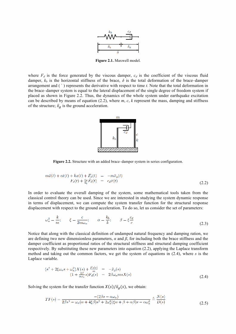
Figure 2.1. Maxwell model.
Blank line 11 pt Blank line 11 pt where Fd is the force generated by the viscous damper, cd is the coefficient of the viscous fluid damper, kb is the horizontal stiffness of the brace, δ is the total deformation of the brace–damper arrangement and ( ̇ ) represents the derivative with respect to time t. Note that the total deformation in the brace–damper system is equal to the lateral displacement of the single degree of freedom system if placed as shown in Figure 2.2. Thus, the dynamics of the whole system under earthquake excitation can be described by means of equation (2.2), where m, c, k represent the mass, damping and stiffness of the structure; !! is the ground acceleration. Blank line 11 pt
Blank line 10 pt
Figure 2.2. Structure with an added brace–damper system in series configuration.
(2.2) In order to evaluate the overall damping of the system, some mathematical tools taken from the classical control theory can be used. Since we are interested in studying the system dynamic response in terms of displacement, we can compute the system transfer function for the structural response displacement with respect to the ground acceleration. To do so, let us consider the set of parameters: Blank line 11 pt
(2.3) Blank line 11 pt Notice that along with the classical definition of undamped natural frequency and damping ration, we are defining two new dimensionless parameters, α and β, for including both the brace stiffness and the damper coefficient as proportional ratios of the structural stiffness and structural damping coefficient respectively. By substituting these new parameters into equation (2.2), applying the Laplace transform method and taking out the common factors, we get the system of equations in (2.4), where s is the Laplace variable. Blank line 11 pt
(2.4) Blank line 11 pt Solving the system for the transfer function ! ! /!!(!), we obtain: Blank line 11 pt
(2.5)
Blank line 11 pt The so–called poles of a transfer function are the values of s that cause the transfer function to become infinite, in other words, the roots of the polynomial D(s). They offer essential quantitative information for the analysis and design of control systems. Particularly, we can use the poles of equation (2.5) for estimating the overall damping ratio of the system, i.e., the total damping available in the system after adding the supplemental damping device and its supporting brace. The overall structural damping ratio can be evaluated by calculating the cosine of the angle of the pole off the horizontal in the s–plane (For further details see e.g., Ogata (1990)). It can be expressed as: Blank line 11 pt
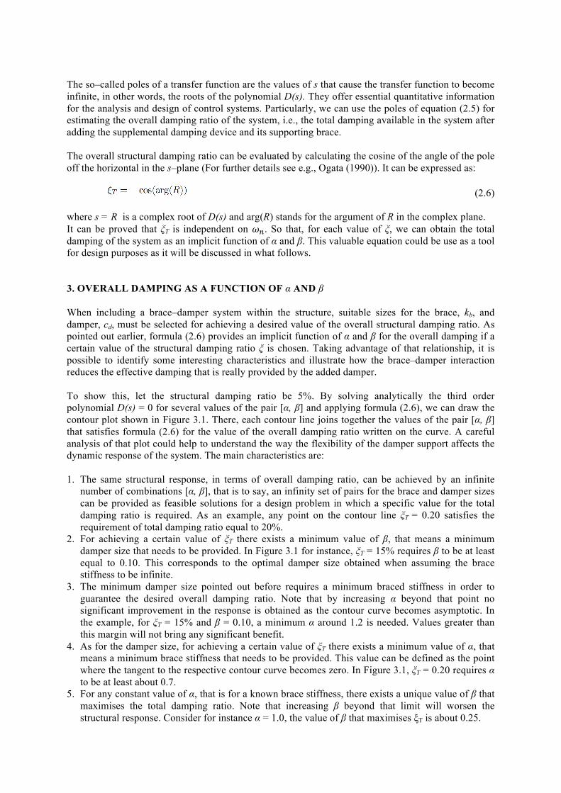
(2.6) Blank line 11 pt where s = R is a complex root of D(s) and arg(R) stands for the argument of R in the complex plane. It can be proved that ξT is independent on !!. So that, for each value of ξ, we can obtain the total damping of the system as an implicit function of α and β. This valuable equation could be use as a tool for design purposes as it will be discussed in what follows. Blank line 11 pt Blank line 11 pt 3. OVERALL DAMPING AS A FUNCTION OF α AND β Blank line 11 pt When including a brace–damper system within the structure, suitable sizes for the brace, kb, and damper, cd, must be selected for achieving a desired value of the overall structural damping ratio. As pointed out earlier, formula (2.6) provides an implicit function of α and β for the overall damping if a certain value of the structural damping ratio ξ is chosen. Taking advantage of that relationship, it is possible to identify some interesting characteristics and illustrate how the brace–damper interaction reduces the effective damping that is really provided by the added damper. To show this, let the structural damping ratio be 5%. By solving analytically the third order polynomial D(s) = 0 for several values of the pair [α, β] and applying formula (2.6), we can draw the contour plot shown in Figure 3.1. There, each contour line joins together the values of the pair [α, β] that satisfies formula (2.6) for the value of the overall damping ratio written on the curve. A careful analysis of that plot could help to understand the way the flexibility of the damper support affects the dynamic response of the system. The main characteristics are: 1. The same structural response, in terms of overall damping ratio, can be achieved by an infinite
number of combinations [α, β], that is to say, an infinity set of pairs for the brace and damper sizes can be provided as feasible solutions for a design problem in which a specific value for the total damping ratio is required. As an example, any point on the contour line ξT = 0.20 satisfies the requirement of total damping ratio equal to 20%.
2. For achieving a certain value of ξT there exists a minimum value of β, that means a minimum damper size that needs to be provided. In Figure 3.1 for instance, ξT = 15% requires β to be at least equal to 0.10. This corresponds to the optimal damper size obtained when assuming the brace stiffness to be infinite.
3. The minimum damper size pointed out before requires a minimum braced stiffness in order to guarantee the desired overall damping ratio. Note that by increasing α beyond that point no significant improvement in the response is obtained as the contour curve becomes asymptotic. In the example, for ξT = 15% and β = 0.10, a minimum α around 1.2 is needed. Values greater than this margin will not bring any significant benefit.
4. As for the damper size, for achieving a certain value of ξT there exists a minimum value of α, that means a minimum brace stiffness that needs to be provided. This value can be defined as the point where the tangent to the respective contour curve becomes zero. In Figure 3.1, ξT = 0.20 requires α to be at least about 0.7.
5. For any constant value of α, that is for a known brace stiffness, there exists a unique value of β that maximises the total damping ratio. Note that increasing β beyond that limit will worsen the structural response. Consider for instance α = 1.0, the value of β that maximises ξT is about 0.25.
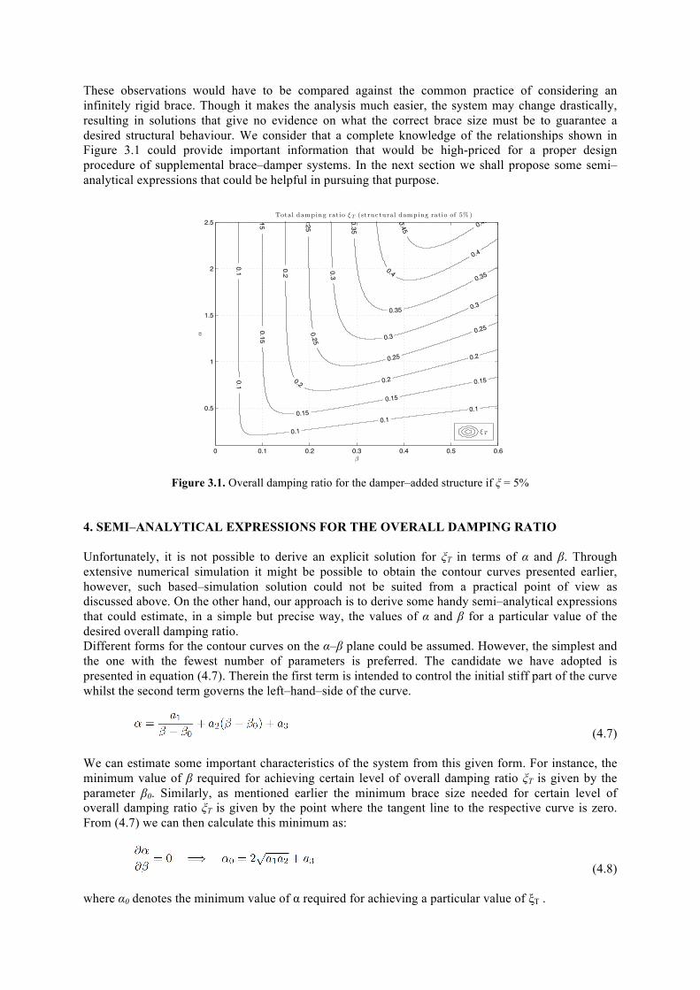
These observations would have to be compared against the common practice of considering an infinitely rigid brace. Though it makes the analysis much easier, the system may change drastically, resulting in solutions that give no evidence on what the correct brace size must be to guarantee a desired structural behaviour. We consider that a complete knowledge of the relationships shown in Figure 3.1 could provide important information that would be high-priced for a proper design procedure of supplemental brace–damper systems. In the next section we shall propose some semi–analytical expressions that could be helpful in pursuing that purpose. Blank line 11 pt
Figure 3.1. Overall damping ratio for the damper–added structure if ξ = 5%
Blank line 11 pt Blank line 11 pt 4. SEMI–ANALYTICAL EXPRESSIONS FOR THE OVERALL DAMPING RATIO Blank line 11 pt Unfortunately, it is not possible to derive an explicit solution for ξT in terms of α and β. Through extensive numerical simulation it might be possible to obtain the contour curves presented earlier, however, such based–simulation solution could not be suited from a practical point of view as discussed above. On the other hand, our approach is to derive some handy semi–analytical expressions that could estimate, in a simple but precise way, the values of α and β for a particular value of the desired overall damping ratio. Different forms for the contour curves on the α–β plane could be assumed. However, the simplest and the one with the fewest number of parameters is preferred. The candidate we have adopted is presented in equation (4.7). Therein the first term is intended to control the initial stiff part of the curve whilst the second term governs the left–hand–side of the curve. Blank line 11 pt
(4.7) Blank line 11 pt We can estimate some important characteristics of the system from this given form. For instance, the minimum value of β required for achieving certain level of overall damping ratio ξT is given by the parameter β0. Similarly, as mentioned earlier the minimum brace size needed for certain level of overall damping ratio ξT is given by the point where the tangent line to the respective curve is zero. From (4.7) we can then calculate this minimum as: Blank line 11 pt
(4.8) Blank line 11 pt where α0 denotes the minimum value of α required for achieving a particular value of ξT .
0.10.1
0.10.1
0.1
150.15
0.15
0.15
0.15
0.2
0.2 0.2
0.2
0.250.25
0.25
0.25
0.3
0.3
0.3
0.35
0.35
0.350.4
0.4
0.45 0.45
!
"
Total damp ing ratio # T (struc tu ral damp ing ratio of 5% )
0 0.1 0.2 0.3 0.4 0.5 0.6
0.5
1
1.5
2
2.5
# T
Suitable values for the coefficients a1, a2 and a3 in equation (4.7) can be obtained by using any curve fitting algorithm on each individual curve for a nominated value of ξT. Particularly, we used the least squares curve fitting method to estimate those optimum coefficients. In addition, note that such coefficients are therefore depending on ξT. From observations, it can be assumed that ai and β0 follow a quadratic law in terms of ξT. So that, after completing the individual fitting for several contour curves and setting up the correspondent quadratic laws, a rule for estimating the set of parameters can be written as: Blank line 11 pt
(4.9)
Blank line 11 pt Thus, all of the information presented in Figure 3.1 can be summarised in formula (4.7) along with the coefficients calculated from (4.9). This will give a good approximation for all 0.10 < ξT < 0.30, which is the practical range of interest. It is worth noticing that this simple fitting procedure can be repeated for any value of the structural damping ξ between 1% and 7% (range of interest in civil structures). Since the aim of this paper is to present the procedure as a suitable way for analysing structures with added dampers for design purposes, we are only presenting here a typical case for a system with ξ = 5%. A complete solution and more general formulas for ξT are currently being developed. Blank line 11 pt Blank line 11 pt 5. NUMERICAL EXAMPLE Blank line 11 pt To illustrate the advantage in using the semi–analytic equations presented above, let us discuss and compare the results obtained from them against the direct solution of formula (2.6). First of all, let us consider a target value for the overall damping ratio as 20% and three different situations: • Determine the brace stiffness for a known damper size, let us say β = 0.4 (See equation (2.3)).
Exhaustive numerical simulations have to be completed for getting α directly from formula (2.6), since a numerical optimisation problem has to be formulated in which the target is to find α subject to keep ξT = 0.20 and β = 0.4. By solving that optimisation problem, it can be found that α = 0.853. Conversely, by following our approach, this can be solved in two simple steps by calculating the parameters ai and β0 from equation (4.9) for ξT = 0.20 as:
and then substituting them along with β = 0.4 in formula (4.7) to obtain α = 0.857. That means the semi–analytical expressions estimate this value with an error of 0.5%. Figure 4.1 shows the contour curves calculated from both solving formula (2.6) numerically and the semi–analytical expressions.
• Determine the minimum brace stiffness needed for ξT = 0.2. Again a constrained numerical optimisation problem must be solved form formula (2.6). α0 can be found by formulating an optimisation problem in which the tangent to the curve ξT = 0.2 is required to be zero. This value has been found to be equal to 0.687 as shown in Figure 4.1. Alternatively, by substituting the corresponding values of ai in equation (4.8), this value can straightaway be estimated as α0 = 0.683, that means an estimation error of 0.6%.
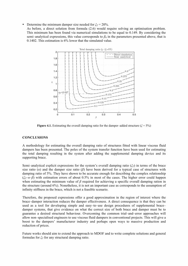
• Determine the minimum damper size needed for ξT = 20%. As before, a direct solution from formula (2.6) would require solving an optimisation problem. This minimum has been found via numerical simulations to be equal to 0.149. By considering the semi–analytical expressions, this value corresponds to β0 in the parameters presented above, that is 0.1402. This estimation is 6% lower that the simulated value.
Blank line 11
Figure 4.1. Estimating the overall damping ratio for the damper–added structure (ξ = 5%) Blank line 11 pt Blank line 11 pt CONCLUSIONS Blank line 11 pt A methodology for estimating the overall damping ratio of structures fitted with linear viscous fluid dampers has been presented. The poles of the system transfer function have been used for estimating the total damping resulting in the system after adding the supplemental damping device and its supporting brace. Semi–analytical explicit expressions for the system’s overall damping ratio (ξT) in terms of the brace size ratio (α) and the damper size ratio (β) have been derived for a typical case of structures with damping ratio of 5%. They have shown to be accurate enough for describing the complex relationship (ξT–α–β) with estimation errors of about 0.5% in most of the cases. The higher error could happen when estimating the minimum value of β required for achieving a specific overall damping ration in the structure (around 6%). Nonetheless, it is not an important case as corresponds to the assumption of infinity stiffness in the brace, which is not a feasible scenario. Therefore, the proposed expressions offer a good approximation in the region of interest where the brace–damper interaction reduces the damper effectiveness. A direct consequence is that they can be used as a tool for developing simple and easy–to–use design procedures of supplemental brace– damper systems, that give evidence on what the correct size of both brace and damper must be to guarantee a desired structural behaviour. Overcoming the common trial–and–error approaches will allow non–specialised engineers to use viscous fluid dampers in conventional projects. This will give a boost to the dampers’ manufacturer industry and perhaps open ways to massive production and reduction of prices. Future works should aim to extend the approach to MDOF and to write complete solutions and general formulas for ξT for any structural damping ratio. Blank line 11 pt
0 0.1 0.2 0.3 0.4 0.5
0.2
0.4
0.6
0.8
1
1.2
1.4
1.6
1.8
2
0.10.125
0.15
0.175
0.2
0.225
0.25
0.275
0.3
!
"Total damping ratio #T (#=5%)
"0=0.687
Direct simulationSemi–analytical
AKCNOWLEDGEMENT This work has been funded by the Royal Academy of Engineering through a Newton International Fellowship. The support is gratefully acknowledged. Blank line 10 pt Blank line 10 pt REFERENCES Blank line 10 pt Agranovich, G., & Ribakov, Y. (2010). A method for efficient placement of active dampers in seismically
excited structures. Structural Control and Health Monitoring, 17:5, 513–531. Chen, Y.T., & Chai, Y.H. (2011). Effects of brace stiffness on performance of structures with supplemental
Maxwell model–based brace–damper systems. Earthquake Engineering & Structural Dyn, 40:1, 75–92. Council, B. S. S. (1997). NEHRP Guidelines for the Seismic Rehabilitation of Buildings. Federal Emergency
Management Agency Washington, D.C. USA (FEMA 273 ed.). Dyke, S. J. (2005). Current directions in structural control in the US. In Proceedings of the 9th World Seminar
on Seismic Isolation, Energy Dissipation and Active Vibration Control of Structures. Kobe, Japan. Gluck, N., Reinhorn, A. M., & Levy, R. (1996). Design of supplemental dampers for control of structures.
Journal of Structural Engineering, 122:12, 1394–1399. Hanson, R. D., & Soong, T. T. (2001). Seismic Design with Supplemental Energy Dissipation Devices. MNO–8.
EERI Monograph. Lavan, O., & Levy, R. (2005). Optimal design of supplemental viscous dampers for irregular shear-frames in the
presence of yielding. Earthquake Engineering & Structural Dynamics, 34:8, 889–907. Lavan, O., & Levy, R. (2006). Optimal design of supplemental viscous dampers for linear framed structures.
Earthquake Engineering & Structural Dynamics, 35:3, 337–356. Levy, R., & Lavan, O. (2009). Quantitative comparison of optimization approaches for the design of supple-
mental damping in earthquake engineering practice. Journal of Structural Engineering, 135:3, 321–325. Liu, W., Tong, M., & Lee, G. C. (2004). Simple procedure for preliminary design of structural damper. In Proc.
13th World Conference on Earthquake Engineering. Vancouver, Canada. Paper No 2021. Lopez, D. (2001). A simple method for the design of optimal damper con- figuration in MDOF structures.
Earthquake Spectra, 17:3, 387–398. Miyamoto, H. K., & Hanson, R. D. (2004). Structural practices. Seismic dampers: State of the applications.
Structure Magazine, 1, 16–18. Ogata, K. (1990). Modern control engineering. (2nd ed.). Upper Saddle River, NJ, USA: Prentice–Hall, Inc. Park, J.H., Kim, J., & Min, K.W. (2004). Optimal design of added viscoelastic dampers and supporting braces.
Earthquake Engineering & Structural Dynamics, 33:4, 465–484. Ramirez, O. M., Constantinou, M. C., Kircher, C. A., Whittaker, A. S., Johnson, M. W., Gomez, J. D., &
Chrysostomou, C. Z. (2001). Development and Evaluation of Simplified Procedures for Analysis and Design of Buildings with Passive Energy Dissipation Systems. Technical Report MCEER-00-0010 Multidisciplinary Center for Earthquake Engineering Research State University of New York at Buffalo.
Ribakov, Y., & Reinhorn, A. M. (2003). Design of amplified structural damping using optimal considerations. Journal of Structural Engineering, 129:10, 1422–1427.
Silvestri, S., Gasparini, G., & Trombetti, T. (2010). A five–step procedure for the dimensioning of viscous dampers to be inserted in building structures. Journal of Earthquake Engineering, 14:3, 417–447
Spencer, B. F., & Nagarajaiah, S. (2003). State-of-the-art in structural control. ASCE Journal of Structural Engineering, 129:7, 845–856.
Sullivan, T., & Lago, A. (2012). Towards a simplified direct DBD procedure for the seismic design of moment resisting frames with viscous dampers. Engineering Structures, 35,300–320.
Yang, J. N., Lin, S., Kim, J. H., & Agrawal, A. K. (2002). Optimal design of passive energy dissipation systems based on H∞ and H2 performances. Earthquake Engineering and Structural Dynamics, 31:4, 921–936.