estimating the deformation modulus of jointed rock...
TRANSCRIPT

JME Journal of Mining & Environment,
Vol.2, No.2, 2011, 146-156.
Estimating the deformation modulus of jointed rock mass under
multilateral loading condition using analytical methods
M. Ebadi1, S. Karimi Nasab
2*, H. Jalalifar
3
1-Master of rock mechanics, Shahid Bahonar University of Kerman.
2-Assistant Professor, Mining Engineering Department, Shahid Bahonar University of Kerman, 3-Associate Professor, Oil and Gas Engineering Department, Shahid Bahonar University of Kerman.
Received 18 Jan 2012; received in revised form 9 Mar 2012; accepted 5 Apr 2012
*Corresponding author: [email protected] (S. Kariminasab)
Abstract
Determination of rock mass deformation modulus is very important in different projects, especially in civil and mining engineering works. In-situ measurements such as dilatometer, plate load and flat jack methods may be applied to determine the deformation modulus. However, these methods are very expensive and time- consuming. Analytical methods are very useful approaches which can also be used to estimate rock mass deformation modulus. Using these methods, the parameters influencing the rock mass modulus can also be evaluated. Analytical methods are based on the resultant displacement of rock mass and joints which are finally used to predict the rock modulus. It should be mentioned that none of the available analytical models could present a model to consider the effect of lateral stresses on rock mass modulus calculations. Therefore, this paper tries to investigate the effect of intermediate principal stress (σ2) and minimum principal stress (σ3) on the deformation modulus of jointed rock mass.
Keywords: Deformation modulus; rock mass; analytical method; laterals stress.
1. IntroductionMany researchers have carried out various laboratory tests to investigate the effect of lateral stress on deformation modulus of jointed rock mass. For example, Yaji has carried out different tests on intact and jointed rock samples of Paris gypsum, sandstone and granite types. He has presented the results as stress- strain curves and failure curves for different lateral stresses. Finally, he has suggested an equation for calculation of elastic modulus with lateral stress applied on intact rock [1]. Arora has presented an equation to calculate elastic modulus of jointed rock mass using elastic modulus of intact rock and lateral stress (σ3) [2]. Having carried out a large number of tests, Kulhawy developed an equation to calculate rock mass elastic modulus using intact rock elastic
modulus and lateral stress (σ3) [3]. Fahimifar carried out triaxial tests on a schist sample and found the increase curve of secant modulus at 50% of failure point for different angles and lateral stresses [4]. Using wave propagation method through triaxial test cell, Homand et al. showed that elastic modulus and shear modulus could be exponential functions of 1+σ3 and used a mathematical model to illustrate their results [5]. Nasseri et al. carried out tests on four different rock types. Theresults showed that tangential elastic modulus in 50% of failure point nonlinearly increases with increase in lateral stress for various angles [6]. Li suggested a method for the determination of rock mass modulus based on the effect superposition principle. In this method, deformation modulus is

Ebadi et al./ Journal of Mining & Environment, Vol.2, No.2, 2011
147
firstly calculated for single joints. Then, the equation is presented to calculate deformation modulus in a block which contains single and multi joint sets [7]. Kulatilake et al. developed a model to estimate rock block strength and deformability in three-dimensional situation. From the results, the mean rock mass strength was found to be 47% of the mean intact rock strength. In addition the mean rock mass modulus was found to be 51% of the intact rock modulus. He found that the level of rock mass weakening is due to the presence of fractures [8]. However, lateral stress is not considered in these equations. As mentioned above, none of the available analytical models could present a model to consider the effect of lateral stresses on rock mass modulus calculations. Therefore, this research tries to investigate the effect of lateral
stress on deformation modulus of jointed rock mass.
2. Displacement due to a single joint A blocky model containing a single joint is illustrated in figure 1. If stress is applied on this block, normal and shear stresses are developed on joint surface. Having calculated the stresses, displacement can be calculated. Considering 𝛥𝜎 as the loading increment, then normal stress
increase (𝛥𝜎n) and shear stress increase (𝜎𝜏) applied on the surface of i
th joint are calculated
from equations (1) and (2) respectively [10]:
𝜎𝛥 𝜎𝛥 (1)
𝜎𝜏 𝜎𝛥 (2)
Where, θ is the angle between 𝛥1 strike and normal to the joint surface.
Figure 1. A block of rock containing a single joint
The displacement due to stresses is the resultant of displacements due to all principal stresses (maximum principal stress and lateral stress) applied on the block, which are calculated in the
following sections. It should be noted that
and
are the displacement of ith
joint during
𝛥1 and 𝛥3 along y direction respectively.
2.1. Displacement determination due to σ1
Normal and shear displacement increase due to 𝛥1 are calculated from equations (3) and (4) respectively [7]:
Δ
(3)
Δ
(4)
If displacement in the shear plane (normal and shear directions) is projected along the maximum
stress, the value of ith joint displacement during 𝛥1
loading is obtained from equation (5) as displayed in figure 1 [7]:
[
]
(5)
Where, kni,σ and ksi,σ are normal and shear stiffness
of ith joint due to 𝛥 stress. It should be noted that
normal and shear stiffness of rock joints are obtained from joint profile configuration which is based on test results. These tests show that as the normal stress increases, so do the normal and shear stiffness [9].

Ebadi et al./ Journal of Mining & Environment, Vol.2, No.2, 2011
148
2.2. The effect of σ 3 on displacement If σ3 is applied perpendicularly to joint plane, then
increased normal (𝜎dni) and shear (𝜎dsi) displacements due to σ3 are calculated from equations (6) and (7) respectively:
Δ
(6)
Δ
(7)
In order to calculate displacement of ith joint
during σ3 loading, the displacement of 𝜎di3y
along maximum stress is calculated from equation (8). According to this equation, shear force due to lateral stress is the increasing factor of jointed rock mass modulus and normal force due to lateral stress is the decreasing factor of jointed rock mass modulus. Therefore, if lateral stress increases, the deformation modulus of jointed rock mass increases (see Figure 1).
[
]
(8)
2.3. Calculation of displacement due to σ2 If σ2 is applied perpendicularly to joint plane, then
increased normal (𝜎dni) and shear (𝜎dsi)
displacements due to 𝛥2 are calculated from equations (9) and (10) respectively:
Δ
(9)
Δ
(10)
In these equations, the angle between σ2 and normal to the joint plane is the supplementary angle of θi (figure 2). Having calculated the displacement of i
th joint
during 𝛥2 loading, the value of displacement 𝜎di2x
along x is obtained from equation (11):
[
]
(11)
Similarly, in order to calculate displacement of ith
joint during σ2 loading, the displacement of 𝜎di2y
along y is calculated from equation (12).
[
]
(12)
2.4. Determination of total joint displacement In order to calculate the total displacement, the
displacement due to 𝛥1 is accumulated with the
displacements due to 𝛥2 and 𝛥3 along y.
In practice, 𝛥2 and 𝛥3 are perpendicular and cannot be normal to joint plane simultaneously. If
𝜔 is the angle between 𝛥3 and joint plane (figure 2), the total joint displacement due to three stresses applied simultaneously is calculated from equation (13).
[
]
𝜔
[
])
𝜔
[
]
(13)
It should be noted that when the angle between σ3
stress and joint plane (𝜔) is equal to 90 degrees,
only 𝛥3 appears in the equations and 𝛥2 does not affect modulus calculations. It is a particular case that one of confining stresses is not taken into account; however there are numerous cases that all axial and confining stresses affect the joint confinement and displacement which are considered in equation 13.
3. Prediction of rock mass modulus containing
a joint set
The summation of a rock block displacement containing one joint set is the summation of intact rock displacement and joint set displacement. Equation (14) can be used to calculate elastic displacement [7].
(14)
Where E is Young’s modulus of intact rock and L is the sample length. Equation (15) calculates final
displacement in sample (𝜎d), the summation of displacements due to intact rock (equation (14)) and joints (equation (13)) [7].

Ebadi et al./ Journal of Mining & Environment, Vol.2, No.2, 2011
149
∑
(15)
There are m single joints in a joint set and total displacement of the block is due to displacement of all these joints and intact rock. Equation (16) can be used to calculate joints number along sample length (L) (figure (3)) [10].
(16)
When displacement in sample is calculated, deformation modulus of rock block with one joint set can be obtained from equation (17).
∑( [
]
[
]
[
])
(17)
Finally, substituting equation (16) in equation (17) for one joint set with specified joints number and assuming constant joint properties and spacing, equation (18) is obtained.
([
]
[
]
[
])
4. Estimation of rock mass modulus containing
several joint sets In calculating displacement of a joint set, it is
assumed that 𝛥3 is perpendicular to the joint plane
(figure 3). However, when a block contains several joint sets, the applied force is not perpendicular to the joint plane and only the normal component of the force is considered in equations. The force component which is parallel to the joint plane does not cause vertical
displacement. Entering 𝜔 in equation (18) results in equation (19).
∑( [
]
[
]
[
])
(19)
For the block with N joint sets, total displacement is calculated as the sum of elastic displacement of intact rock and displacement of each joint set. Therefore, considering N joint sets, equation (19) is re-written as equation (20).
∑ ((
) ([
]
[
]
[
]))
(20)
If the values of minimum lateral stress (𝛥3) and
intermediate lateral stress (𝛥2) are neglected in equation (20), the equation suggested by Li [7] is obtained which shows the accuracy of presented calculations (equation (21)).
∑((
) (
))
(21)

Ebadi et al./ Journal of Mining & Environment, Vol.2, No.2, 2011
150
Figure 2. Schematic view of force direction
Figure 3. A block with one joint set and illustrating σ3 loading direction and joint plane
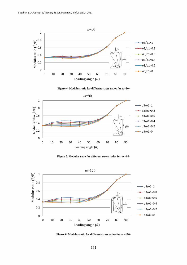
5. Analyses of the results In this section, the effect of various factors on rock mass deformation modulus is evaluated. In order to investigate the effect of each parameter, other factors are considered constant.
5.1. The effect of minimum lateral stress (𝛥3)
and its loading angle (𝜽)
The effect of minimum lateral stress (𝛥3) and its loading angle (θ) on a schist sample (table 1) is investigated considering zero value for
intermediate lateral stress (𝛥2) (figures 4, 5 and 6).
In the analysis of each joint set with different 𝜔,
when minimum lateral stress (𝛥3) is increased, the modulus is also increased. The reason is that 1-
normal stress due to minimum lateral stress (𝛥3) is increased resulting in more displacement in joint, and 2- shear stress is increased resulting in upward displacement of joint. These two displacements result in an upward displacement which increases the modulus. Approaching hydrostatic conditions results in more
displacement due to minimum lateral stress (𝛥3),
therefore the modulus reaches its maximum value.
In each joint set, as the 𝜔 angle approaches 90◦,
the effect of minimum lateral stress (𝛥3) is increased. Figures 4, 5 and 6 show, an increase in confining stress results in a decrease of the displacement and therefore, rock mass modulus increases.
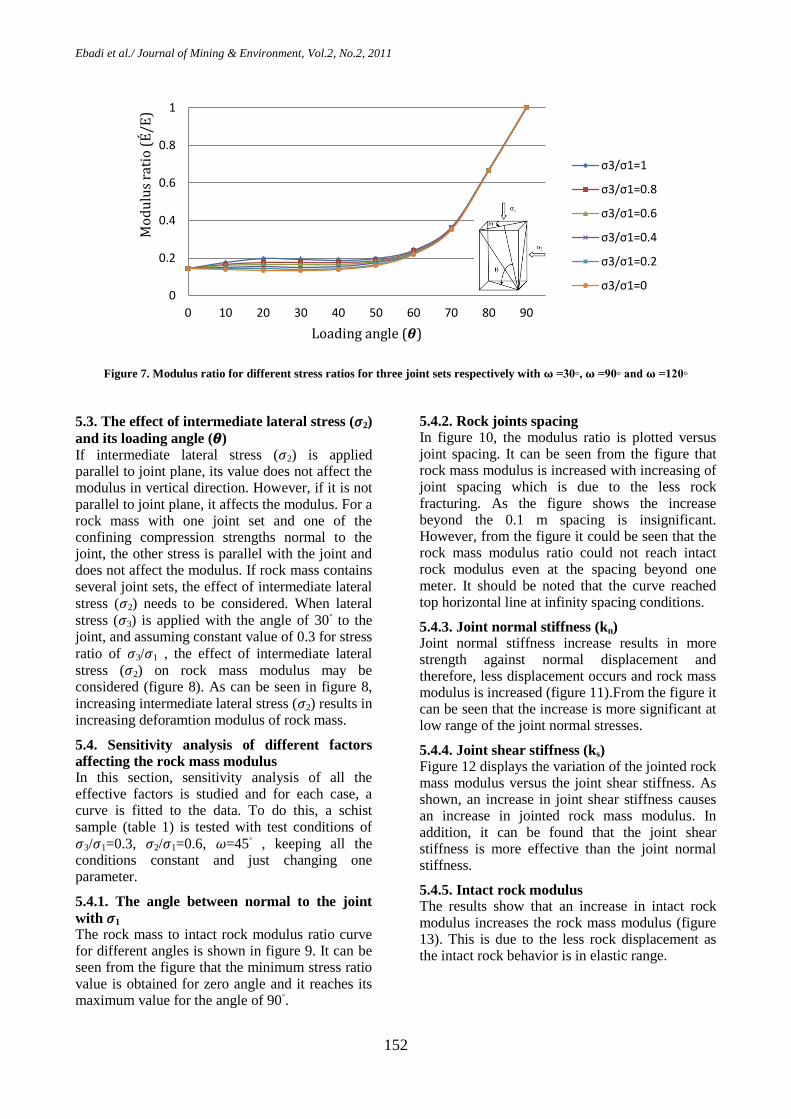
5.2. The models evaluations for several joint
sets
It is considered that three joint sets with different
𝜔 angles (30◦, 90
◦ and 120
◦) simultaneously affect
the rock modulus. The effect of these joint sets on modulus ratio for different angles is illustrated in figure 7. As can be seen in figure 7, the modulus ratio variation is insignificant beyond the loading angle greater than 70 degree with increasing the
lateral stresses (𝛥3). However, with increasing the lateral stresses beyond the 70 degree the modulus ratio is dramatically increased and approximately is the same for all lateral stress ratios.
Table 1. Schist properties [9]
Spacing
S (m)
Shear stiffness
Ks (GPa/m)
Normal stiffness
Kn (GPa/m)
Elastic modulus
E (GPa)
Poisson’s coefficient
0.05 231 660 66 0.29
Ebadi et al./ Journal of Mining & Environment, Vol.2, No.2, 2011
151
Figure 4. Modulus ratio for different stress ratios for 𝛚=30◦
Figure 5. Modulus ratio for different stress ratios for 𝛚 =90◦
Figure 6. Modulus ratio for different stress ratios for 𝛚 =120◦
0
0.2
0.4
0.6
0.8
1
0 10 20 30 40 50 60 70 80 90
Mo
du
lus
rati
o (
É/E
)
Loading angle (𝜽)
ω=30
σ3/σ1=1
σ3/σ1=0.8
σ3/σ1=0.6
σ3/σ1=0.4
σ3/σ1=0.2
σ3/σ1=0
0
0.2
0.4
0.6
0.8
1
0 10 20 30 40 50 60 70 80 90
Mo
du
lus
rati
o (
É/E
)
Loading angle (𝜽)
ω=90
σ3/σ1=1
σ3/σ1=0.8
σ3/σ1=0.6
σ3/σ1=0.4
σ3/σ1=0.2
σ3/σ1=0
0
0.2
0.4
0.6
0.8
1
0 10 20 30 40 50 60 70 80 90
Mo
du
lus
rati
o (
É/E
)
Loading angle (𝜽)
ω=120
σ3/σ1=1
σ3/σ1=0.8
σ3/σ1=0.6
σ3/σ1=0.4
σ3/σ1=0.2
σ3/σ1=0
Ebadi et al./ Journal of Mining & Environment, Vol.2, No.2, 2011
152
Figure 7. Modulus ratio for different stress ratios for three joint sets respectively with 𝛚 =30◦, 𝛚 =90◦ and 𝛚 =120◦
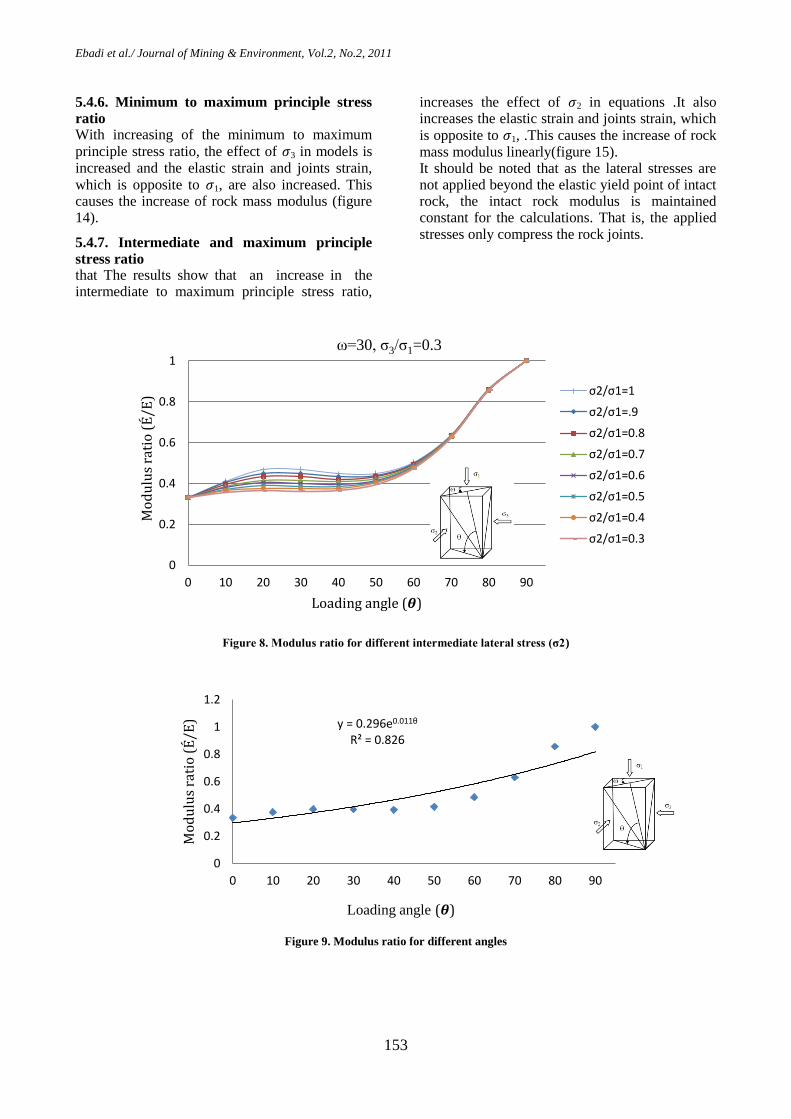
5.3. The effect of intermediate lateral stress (𝛥2)
and its loading angle (𝜽) If intermediate lateral stress (𝛥2) is applied parallel to joint plane, its value does not affect the modulus in vertical direction. However, if it is not parallel to joint plane, it affects the modulus. For a rock mass with one joint set and one of the confining compression strengths normal to the joint, the other stress is parallel with the joint and does not affect the modulus. If rock mass contains several joint sets, the effect of intermediate lateral
stress (𝛥2) needs to be considered. When lateral
stress (𝛥3) is applied with the angle of 30◦ to the
joint, and assuming constant value of 0.3 for stress
ratio of 𝛥3/𝛥1 , the effect of intermediate lateral
stress (𝛥2) on rock mass modulus may be considered (figure 8). As can be seen in figure 8,
increasing intermediate lateral stress (𝛥2) results in increasing deforamtion modulus of rock mass.
5.4. Sensitivity analysis of different factors
affecting the rock mass modulus In this section, sensitivity analysis of all the effective factors is studied and for each case, a curve is fitted to the data. To do this, a schist sample (table 1) is tested with test conditions of
𝛥3/𝛥1=0.3, 𝛥2/𝛥1=0.6, 𝜔=45◦ , keeping all the
conditions constant and just changing one parameter.
5.4.1. The angle between normal to the joint
with 𝛥1 The rock mass to intact rock modulus ratio curve for different angles is shown in figure 9. It can be seen from the figure that the minimum stress ratio value is obtained for zero angle and it reaches its maximum value for the angle of 90
◦.
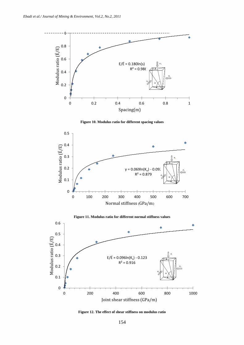
5.4.2. Rock joints spacing In figure 10, the modulus ratio is plotted versus joint spacing. It can be seen from the figure that rock mass modulus is increased with increasing of joint spacing which is due to the less rock fracturing. As the figure shows the increase beyond the 0.1 m spacing is insignificant. However, from the figure it could be seen that the rock mass modulus ratio could not reach intact rock modulus even at the spacing beyond one meter. It should be noted that the curve reached top horizontal line at infinity spacing conditions.
5.4.3. Joint normal stiffness (kn) Joint normal stiffness increase results in more strength against normal displacement and therefore, less displacement occurs and rock mass modulus is increased (figure 11).From the figure it can be seen that the increase is more significant at low range of the joint normal stresses.
5.4.4. Joint shear stiffness (ks) Figure 12 displays the variation of the jointed rock mass modulus versus the joint shear stiffness. As shown, an increase in joint shear stiffness causes an increase in jointed rock mass modulus. In addition, it can be found that the joint shear stiffness is more effective than the joint normal stiffness.
5.4.5. Intact rock modulus The results show that an increase in intact rock modulus increases the rock mass modulus (figure 13). This is due to the less rock displacement as the intact rock behavior is in elastic range.
0
0.2
0.4
0.6
0.8
1
0 10 20 30 40 50 60 70 80 90
Mo
du
lus
rati
o (
É/E
)
Loading angle (𝜽)
σ3/σ1=1
σ3/σ1=0.8
σ3/σ1=0.6
σ3/σ1=0.4
σ3/σ1=0.2
σ3/σ1=0
Ebadi et al./ Journal of Mining & Environment, Vol.2, No.2, 2011
153
5.4.6. Minimum to maximum principle stress
ratio With increasing of the minimum to maximum
principle stress ratio, the effect of 𝛥3 in models is increased and the elastic strain and joints strain,
which is opposite to 𝛥1, are also increased. This causes the increase of rock mass modulus (figure 14).
5.4.7. Intermediate and maximum principle
stress ratio that The results show that an increase in the intermediate to maximum principle stress ratio,
increases the effect of 𝛥2 in equations .It also increases the elastic strain and joints strain, which
is opposite to 𝛥1, .This causes the increase of rock mass modulus linearly(figure 15). It should be noted that as the lateral stresses are not applied beyond the elastic yield point of intact rock, the intact rock modulus is maintained constant for the calculations. That is, the applied stresses only compress the rock joints.
Figure 8. Modulus ratio for different intermediate lateral stress (σ2)
Figure 9. Modulus ratio for different angles
0
0.2
0.4
0.6
0.8
1
0 10 20 30 40 50 60 70 80 90
Mo
du
lus
rati
o (
É/E
)
Loading angle (𝜽)
ω=30, σ3/σ1=0.3
σ2/σ1=1
σ2/σ1=.9
σ2/σ1=0.8
σ2/σ1=0.7
σ2/σ1=0.6
σ2/σ1=0.5
σ2/σ1=0.4
σ2/σ1=0.3
y = 0.296e0.011θ R² = 0.826
0
0.2
0.4
0.6
0.8
1
1.2
0 10 20 30 40 50 60 70 80 90
Mo
du
lus
rati
o (
É/E
)
Loading angle (𝜽)
Ebadi et al./ Journal of Mining & Environment, Vol.2, No.2, 2011
154
Figure 10. Modulus ratio for different spacing values
Figure 11. Modulus ratio for different normal stiffness values
Figure 12. The effect of shear stiffness on modulus ratio
E/É = 0.180ln(s) + 0.980 R² = 0.986
0
0.2
0.4
0.6
0.8
1
0 0.2 0.4 0.6 0.8 1
Mo
du
lus
rati
o (
É/E
)
Spacing(m)
y = 0.069ln(Kn) - 0.092 R² = 0.879
0
0.1
0.2
0.3
0.4
0.5
0 100 200 300 400 500 600 700
Mo
du
lus
rati
o (
É/E
)
(GPa/m) Normal stiffness
E/É = 0.096ln(Ks) - 0.123 R² = 0.916
0
0.1
0.2
0.3
0.4
0.5
0.6
0 200 400 600 800 1000
Mo
du
lus
rati
o (
É/E
)
(GPa/m) Joint shear stiffness

Ebadi et al./ Journal of Mining & Environment, Vol.2, No.2, 2011
155
Figure 13. Rock mass modulus versus different intact rock modulus
Figure 14. Modulus ratio versus different stress ratios
Figure 15. Modulus ratio for different stress coefficients
y = 0.8787x0.8542 R² = 0.9874
0
5
10
15
20
25
30
35
40
45
50
0 20 40 60 80 100
(G
Pa
) R
ock
mas
s m
od
ulu
s
Intact rock modulus (GPa)
E/É = 0.062(σ3/σ1) + 0.395 R² = 0.998
0.38
0.39
0.4
0.41
0.42
0.43
0.44
0 0.1 0.2 0.3 0.4 0.5 0.6
Mo
du
lus
rati
o (
É/E
)
Stress coefficients σ3/σ1
E/É= 0.057(σ2/σ1) + 0.379 R² = 0.998
0.39
0.4
0.41
0.42
0.43
0.44
0.45
0.3 0.4 0.5 0.6 0.7 0.8 0.9 1
Mo
du
lus
rati
o (
É/E
)
Stress coefficients σ2/σ1
Ebadi et al./ Journal of Mining & Environment, Vol.2, No.2, 2011
156
6. Conclusions According to the results obtained from the developed analytical model, the followings can be deduced:
- Shear and normal stresses due to the lateral stresses respectively increase and decrease the modulus of jointed rock mass.
- The modulus of jointed rock mass increases with the increase of the lateral stresses.
- Increase of the minimum confining stress (σ3) and intermediate lateral stress (σ2) causes an increase of the jointed rock mass modulus.
- As ω angle approaches the value of 90◦,
the effect of minimum lateral stress (σ3) increases.
- Increasing the angle between joint normal and σ1, spacing, joint normal stiffness (kn), joint shear stiffness (ks), and principle to confining stresses ratio results in the rock mass modulus increase.
- Joint normal and shear stiffness are much more effective at low values, less than 200GPa/m, on rock mass deformation modulus and appears almost steady beyond this value.
- Both confining stressess affect the rock mass deformation modulus linearly.
References
[1]. Yaji, R. K. (1984). Shear strength and deformation
of jointed rocks. Ph.D. thesis, Indian Institute of
Technology, Delhi, India.
[2]. Arora, V. K. (1987). Strength and deformation
behavior of jointed rocks. Ph.D. thesis, IIT Delhi,
India.
[3]. Kulhawy, F. H. (1975). Stress deformation
properties of rock and rock discontinuities. Engineering
Geology, 9: 327-350.
[4]. Fahimifar, A. (2004). Strength and deformation
properties of a schist rock in Isfahan, Iranian Journal of
Science and Technology, Transaction B, 28: B5.
[5]. Homand, F., Morel, E., Henry, J.P., CuxacP,
Hammade, E. (1993). Characterization of the moduli of
elasticity of an anisotropic rock using dynamic and
static methods. International Journal of Rock
Mechanics and Mining Sciences and Geomechanical
Abstract, 30: 527–535.
[6]. Nasseri, M.H.B. Rao, K.S. Ramamurthy, T.
(2003). Anisotropics strength and deformational
behavior of Himalayan schists. International Journal of
Rock Mechanics and Mining Sciences 40: 3–23.
[7]. Li, C. (2001). A Method for graphically presenting
the deformation modulus of jointed rock masses, Rock
Mech. Rock Engng, 34 (1): 67-75.
[8]. Kulatilake.P.H.S.W,J.Park, J.GI.Um. (2003).
Estimation of rock mass strength and deformability in
3-D for a 30m cube at a depth of 485m at Äspö Hard
Rock Laboratory Int.J. Geothecnical and Geological
Engineering. 22: 313-330.
[9]. Bandis, S. C.; Lumsden, A. C., Barton, N. R.
(1983). Fundamentals of rock joint deformation. Int. J.
Rock Mech. Min. Sci. Geomech. Abstr. 20 (6): 249-
268.
[10]. Pinto, J. L. (1970). Deformability of schistous
rocks, Proc., 2nd Congress of the International Society
for Rock Mechanics, Beograd, Jugoslavija, 1: 2-30.