strength of materials - structures1.tcaup.umich.edustrength of materials • hooke's law •...
TRANSCRIPT

University of Michigan, TCAUP Structures I Slide 1 of 26
Architecture 314
Structures I
Strength of Materials
• Hooke's Law
• Young's Modulus
• Stress & Strain
• Deformation
• Thermal Effects
• Analysis – ASD vs. LRFD
• Modes of Failure
University of Michigan, TCAUP Structures I Slide 2 of 26
Robert Hooke1635 - 1703
Hooke, referred to as the Leonardo da Vinci of England, was a prolific engineer, architect and polymath.
Barometer
Microscope (Micrographia)
Pocket watch
Universal joint
Surveyed London (after fire)
Wren’s engineer (St Paul’s dome)
Law of Springs (Hooke’s Law)
Optics
Astronomy (gravity of bodies)
Curator of experiments of the Royal Society
Portrait by Rita Greer, 2009
University of Michigan, TCAUP Structures I Slide 3 of 26
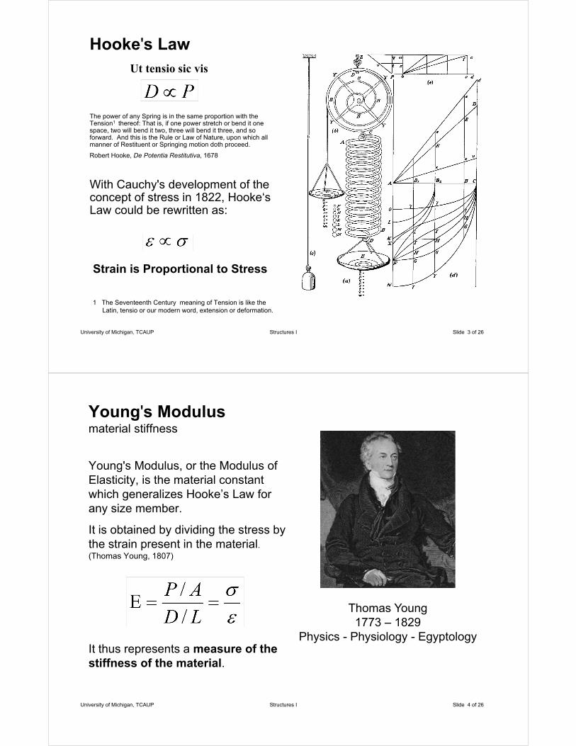
Hooke's LawUt tensio sic vis
The power of any Spring is in the same proportion with the Tension1 thereof: That is, if one power stretch or bend it one space, two will bend it two, three will bend it three, and so forward. And this is the Rule or Law of Nature, upon which all manner of Restituent or Springing motion doth proceed.
Robert Hooke, De Potentia Restitutiva, 1678
With Cauchy's development of the concept of stress in 1822, Hooke‘s Law could be rewritten as:
Strain is Proportional to Stress
1 The Seventeenth Century meaning of Tension is like the Latin, tensio or our modern word, extension or deformation.
University of Michigan, TCAUP Structures I Slide 4 of 26
Young's Modulusmaterial stiffness
Young's Modulus, or the Modulus of Elasticity, is the material constant which generalizes Hooke’s Law for any size member.
It is obtained by dividing the stress by the strain present in the material. (Thomas Young, 1807)
It thus represents a measure of the stiffness of the material.
Thomas Young1773 – 1829
Physics - Physiology - Egyptology
University of Michigan, TCAUP Structures I Slide 5 of 26
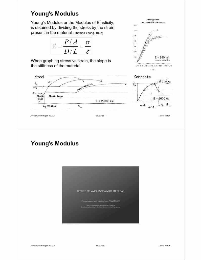
Young's Modulus
Young's Modulus or the Modulus of Elasticity, is obtained by dividing the stress by the strain present in the material. (Thomas Young, 1807)
When graphing stress vs strain, the slope is the stiffness of the material.
E = 29000 ksiE = 3600 ksi
E = 990 ksi
University of Michigan, TCAUP Structures I Slide 6 of 26
Young's Modulus

University of Michigan, TCAUP Structures I Slide 7 of 26
Stress
Stress is the result of some force being applied to an area of some material.
Shear Stress
University of Michigan, TCAUP Structures I Slide 8 of 26
Strain
Strain is the amount of deformation in the material, per unit length.
Deformation occurs either in stretching (tension) or in compressing (compression) but not always at the same rate.

University of Michigan, TCAUP Structures I Slide 9 of 26
Deformation
Using the stress and the Modulus of Elasticity, the total deformation of an axially loaded member can be determined.
Deformation Equation
University of Michigan, TCAUP Structures I Slide 10 of 26
Stiffness
Deformation = Force x Stiffness
Axial
Flexure (constant moment)
Matrix formulation

University of Michigan, TCAUP Structures I Slide 11 of 26
Strain Calculations
The amount of strain deformation is proportional to stress
Neckar Viaduct at WeitingenEngineer Fritz Leonhardt
Completed 1978Span 2952 ftHeight 410 ft
Cable supported span of 866 ftJack height of 118 ftCable length 895 ft
University of Michigan, TCAUP Structures I Slide 12 of 26
Strain Calculations
The amount of strain deformation is proportional to stress
change in height due to stretch = 4.4’

Types of Stress
• Compression
• Tension
• Flexure
• Shear
• Torsion
University of Michigan, TCAUP Structures I Slide 13 of 26
University of Michigan, TCAUP Structures I Slide 14 of 26
Stress Calculations
Find the stress in each material
Axial Compression
The stress equals the force spread over an area.
University of Michigan, TCAUP Structures I Slide 15 of 26
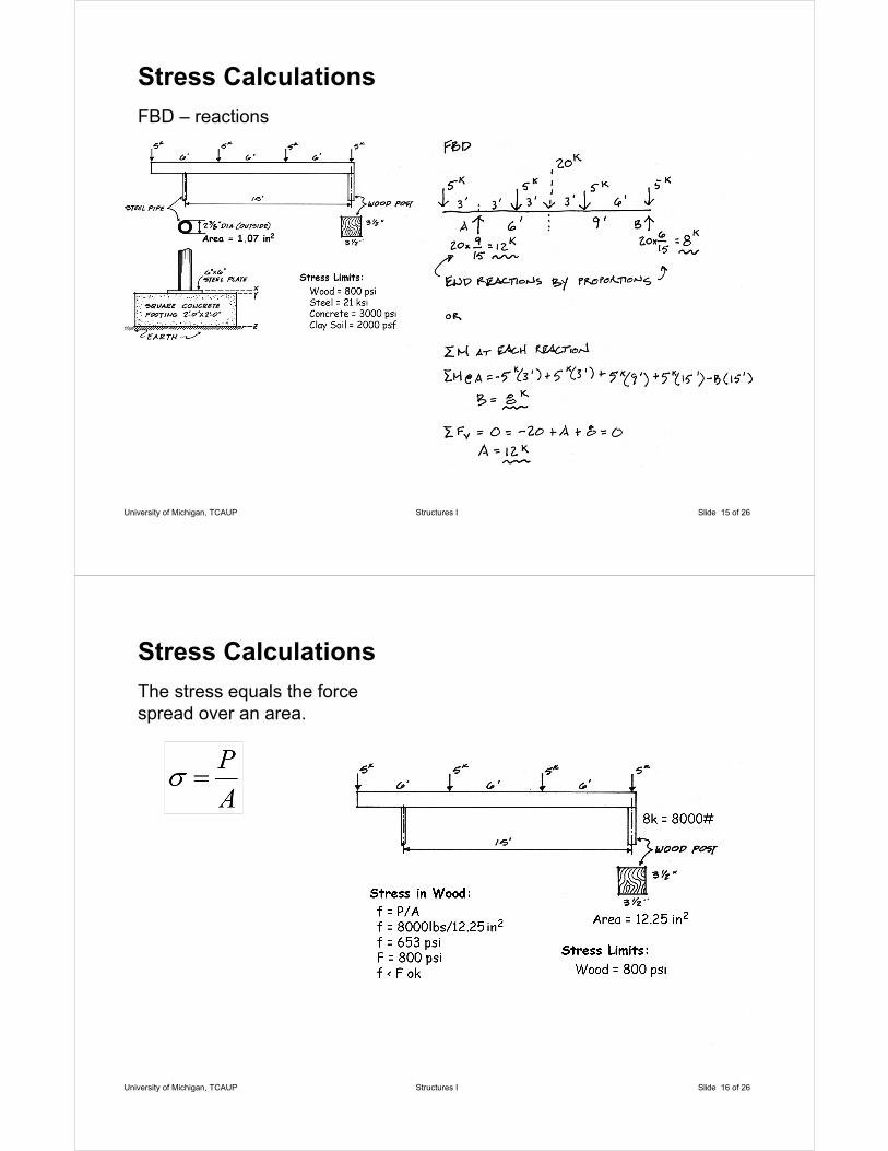
Stress Calculations
FBD – reactions
University of Michigan, TCAUP Structures I Slide 16 of 26
Stress Calculations
The stress equals the force spread over an area.
University of Michigan, TCAUP Structures I Slide 17 of 26
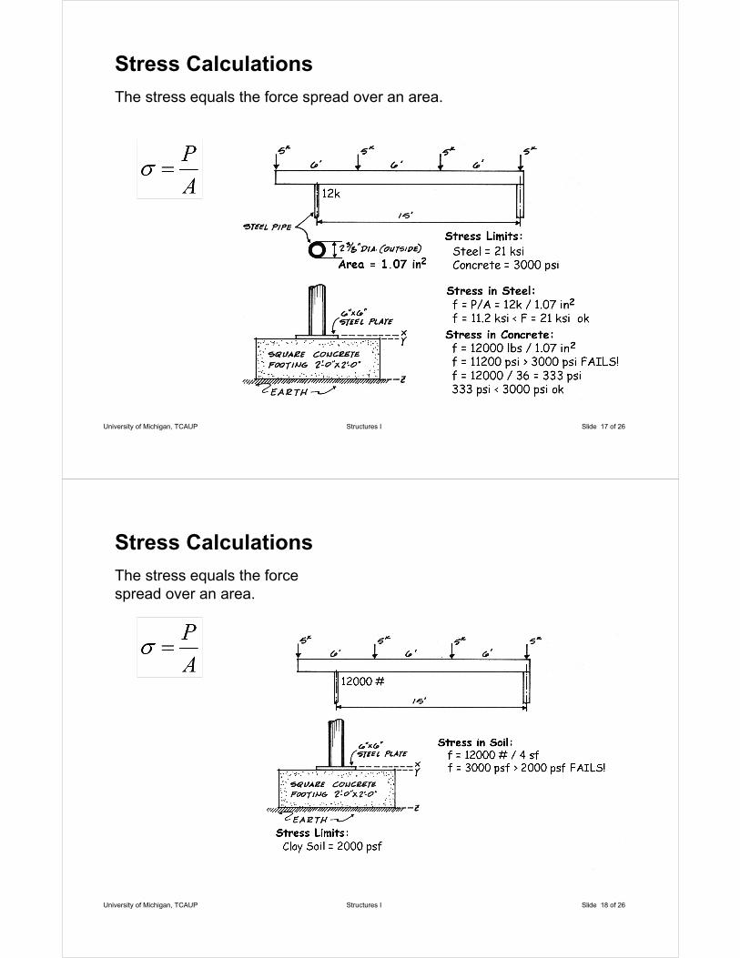
Stress Calculations
The stress equals the force spread over an area.
University of Michigan, TCAUP Structures I Slide 18 of 26
Stress Calculations
The stress equals the force spread over an area.

University of Michigan, TCAUP Structures I Slide 19 of 26
Stress Calculations
Axial Tension
The stress equals the force spread over an area.
Santiago Calatrava - Serreria Bridge - Valencia 2008
University of Michigan, TCAUP Structures I Slide 20 of 26
Stress Calculations
Shear
The stress equals the force spread over an area.

University of Michigan, TCAUP Structures I Slide 21 of 26
Stress Analysis
Allowable Stress Design (ASD)
• use design loads (no F.S. on loads)
• reduce stress by a Factor of Safety F.S.
Load & Resistance Factored Design (LRFD)
• Use loads with safety factor
• Use factor on ultimate strength
University of Michigan, TCAUP Structures I Slide 22 of 26
Modes of Failure
Strength• Tension rupture• Compression crushing
Stability• Column buckling• Beam lateral torsional buckling
Serviceability• Beam deflection• Building story drift• cracking

University of Michigan, TCAUP Structures I Slide 23 of 26
Thermal Induced Stress
The amount of expansion with rising temperature or contraction with falling temperature is described by the coefficient of thermal expansion.
If deformation is restrained, the result will be a thermal induced stress in the member.
The build-up of thermal stress is often prevented by expansion joints.
University of Michigan, TCAUP Structures I Slide 24 of 26
Thermal Induced Stress
The amount of expansion with rising temperature or contraction with falling temperature is described by the coefficient of thermal expansion.
If deformation is restrained, the result will be a thermal induced stress in the member.
The build-up of thermal stress is often prevented by expansion joints.
University of Michigan, TCAUP Structures I Slide 25 of 26
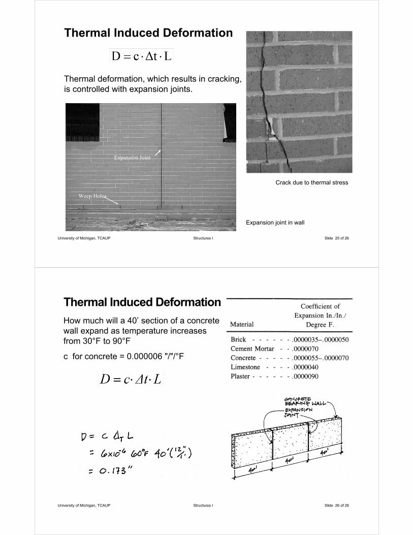
Thermal Induced Deformation
Thermal deformation, which results in cracking, is controlled with expansion joints.
Crack due to thermal stress
Expansion joint in wall
University of Michigan, TCAUP Structures I Slide 26 of 26
Thermal Induced Deformation
How much will a 40’ section of a concrete wall expand as temperature increases from 30°F to 90°F
c for concrete = 0.000006 "/"/°F