es 282 004 - v1.3.0 - telecommunications and internet ... fileetsi 3 etsi es 282 004 v1.3.0...
TRANSCRIPT
ETSI ES 282 004 V1.3.0 (2008-06)
ETSI Standard
Telecommunications and Internet converged Services andProtocols for Advanced Networking (TISPAN);
NGN Functional Architecture;Network Attachment SubSystem (NASS)
ETSI
ETSI ES 282 004 V1.3.0 (2008-06) 2
Reference RES/TISPAN-02050-NGN-R1
Keywords access, system
ETSI
650 Route des Lucioles F-06921 Sophia Antipolis Cedex - FRANCE
Tel.: +33 4 92 94 42 00 Fax: +33 4 93 65 47 16
Siret N° 348 623 562 00017 - NAF 742 C
Association à but non lucratif enregistrée à la Sous-Préfecture de Grasse (06) N° 7803/88
Important notice
Individual copies of the present document can be downloaded from: http://www.etsi.org
The present document may be made available in more than one electronic version or in print. In any case of existing or perceived difference in contents between such versions, the reference version is the Portable Document Format (PDF).
In case of dispute, the reference shall be the printing on ETSI printers of the PDF version kept on a specific network drive within ETSI Secretariat.
Users of the present document should be aware that the document may be subject to revision or change of status. Information on the current status of this and other ETSI documents is available at
http://portal.etsi.org/tb/status/status.asp
If you find errors in the present document, please send your comment to one of the following services: http://portal.etsi.org/chaircor/ETSI_support.asp
Copyright Notification
No part may be reproduced except as authorized by written permission. The copyright and the foregoing restriction extend to reproduction in all media.
© European Telecommunications Standards Institute 2008.
All rights reserved.
DECTTM, PLUGTESTSTM, UMTSTM, TIPHONTM, the TIPHON logo and the ETSI logo are Trade Marks of ETSI registered for the benefit of its Members.
3GPPTM is a Trade Mark of ETSI registered for the benefit of its Members and of the 3GPP Organizational Partners.
ETSI
ETSI ES 282 004 V1.3.0 (2008-06) 3
Contents
Intellectual Property Rights ................................................................................................................................5
Foreword.............................................................................................................................................................5
1 Scope ........................................................................................................................................................6
2 References ................................................................................................................................................6 2.1 Normative references .........................................................................................................................................6 2.2 Informative references........................................................................................................................................7
3 Definitions and abbreviations...................................................................................................................7 3.1 Definitions..........................................................................................................................................................7 3.2 Abbreviations .....................................................................................................................................................7
4 General Description of NASS ..................................................................................................................8 4.1 High level functional overview ..........................................................................................................................8 4.2 High level concepts of NASS.............................................................................................................................9 4.3 Mobility, Nomadism ..........................................................................................................................................9 4.4 Access network level registration.......................................................................................................................9 4.4.1 Implicit authentication ................................................................................................................................10 4.4.1.1 Line authentication................................................................................................................................10 4.4.2 Explicit authentication ................................................................................................................................10 4.4.3 CNG remote network configuration ...........................................................................................................10 4.4.4 TISPAN NGN Service/Applications Subsystems discovery ......................................................................10
5 Functional Architecture..........................................................................................................................11 5.1 Overview ..........................................................................................................................................................11 5.2 Functional Entities............................................................................................................................................12 5.2.1 Network Access Configuration Function (NACF) .....................................................................................12 5.2.2 Access Management Function (AMF)........................................................................................................12 5.2.3 Connectivity session Location and repository Function (CLF) ..................................................................12 5.2.3.1 Information Model ................................................................................................................................13 5.2.4 User Access Authorization Function (UAAF)............................................................................................14 5.2.5 Profile DataBase Function (PDBF) ............................................................................................................14 5.2.6 CNG Configuration Function (CNGCF).....................................................................................................14 5.2.7 Access Relay Function (ARF) ....................................................................................................................14 5.3 Internal Reference points..................................................................................................................................14 5.3.1 Reference Point AMF - NACF (a1)............................................................................................................14 5.3.2 Reference Point NACF - CLF (a2) .............................................................................................................15 5.3.2.1 Bind Indication......................................................................................................................................15 5.3.2.2 Bind Acknowledgement........................................................................................................................15 5.3.2.3 Unbind indication..................................................................................................................................16 5.3.3 Reference Point AMF - UAAF (a3)............................................................................................................16 5.3.4 Reference Point UAAF - CLF (a4).............................................................................................................16 5.3.4.1 Access Profile Push...............................................................................................................................16 5.3.4.2 Access Profile Pull ................................................................................................................................17 5.3.4.3 Remove Access Profile .........................................................................................................................18 5.3.5 Reference Point NACF - UAAF .................................................................................................................18 5.3.6 Reference Point UAAF - UAAF (e5) ..........................................................................................................18 5.3.6.1 Information exchanged on e5.................................................................................................................19 5.4 Interface with the Resource and Admission Control Subsystem (RACS)........................................................19 5.4.1 Interface between CLF and RACF (e4).......................................................................................................19 5.4.1.1 Access Profile Push...............................................................................................................................20 5.4.1.2 Access Profile Pull ................................................................................................................................21 5.4.1.3 IP Connectivity Release Indication .......................................................................................................21 5.5 Interfaces between NASS and the application plane and service control subsystems......................................21 5.5.1 Interface between CLF and service control subsystems (e2).......................................................................21 5.5.1.1 Location Information Query..................................................................................................................21 5.5.1.2 Location Information Response ............................................................................................................22
ETSI
ETSI ES 282 004 V1.3.0 (2008-06) 4
5.6 Reference points between NASS and User Equipment ....................................................................................22 5.6.1 Interface for authentication and IP address allocation (e1)..........................................................................22 5.6.2 Interface between CNGCF and CNG (e3)...................................................................................................22
6 Mapping onto network roles...................................................................................................................23
7 Information flows...................................................................................................................................25 7.1 High level information flows............................................................................................................................25 7.2 PPP based authentication..................................................................................................................................26 7.3 DHCP mode .....................................................................................................................................................27
Annex A (informative): Physical Configurations ................................................................................28
A.1 PPP case .................................................................................................................................................28
A.2 PPP with DHCP configuration ...............................................................................................................29
A.3 DHCP (option 1) ....................................................................................................................................30
A.4 DHCP (option 2) ....................................................................................................................................31
A.5 PANA-based configuration ....................................................................................................................31
Annex B (informative): Bibliography...................................................................................................33
History ..............................................................................................................................................................34
ETSI
ETSI ES 282 004 V1.3.0 (2008-06) 5
Intellectual Property Rights IPRs essential or potentially essential to the present document may have been declared to ETSI. The information pertaining to these essential IPRs, if any, is publicly available for ETSI members and non-members, and can be found in ETSI SR 000 314: "Intellectual Property Rights (IPRs); Essential, or potentially Essential, IPRs notified to ETSI in respect of ETSI standards", which is available from the ETSI Secretariat. Latest updates are available on the ETSI Web server (http://webapp.etsi.org/IPR/home.asp).
Pursuant to the ETSI IPR Policy, no investigation, including IPR searches, has been carried out by ETSI. No guarantee can be given as to the existence of other IPRs not referenced in ETSI SR 000 314 (or the updates on the ETSI Web server) which are, or may be, or may become, essential to the present document.
Foreword This ETSI Standard (ES) has been produced by ETSI Technical Committee Telecommunications and Internet converged Services and Protocols for Advanced Networking (TISPAN).
The present document describes the architecture of the Network Attachment SubSystem (NASS) identified in the overall TISPAN NGN architecture.
ETSI
ETSI ES 282 004 V1.3.0 (2008-06) 6
1 Scope The present document describes the architecture of the Network Attachment SubSystem (NASS) and its role in the TISPAN NGN architecture as defined in ES 282 001 [2].
2 References References are either specific (identified by date of publication and/or edition number or version number) or non-specific.
• For a specific reference, subsequent revisions do not apply.
• Non-specific reference may be made only to a complete document or a part thereof and only in the following cases:
- if it is accepted that it will be possible to use all future changes of the referenced document for the purposes of the referring document;
- for informative references.
Referenced documents which are not found to be publicly available in the expected location might be found at http://docbox.etsi.org/Reference.
For online referenced documents, information sufficient to identify and locate the source shall be provided. Preferably, the primary source of the referenced document should be cited, in order to ensure traceability. Furthermore, the reference should, as far as possible, remain valid for the expected life of the document. The reference shall include the method of access to the referenced document and the full network address, with the same punctuation and use of upper case and lower case letters.
NOTE: While any hyperlinks included in this clause were valid at the time of publication ETSI cannot guarantee their long term validity.
2.1 Normative references The following referenced documents are indispensable for the application of the present document. For dated references, only the edition cited applies. For non-specific references, the latest edition of the referenced document (including any amendments) applies.
[1] ETSI TS 133 203: "Digital cellular telecommunications system (Phase 2+); Universal Mobile Telecommunications System (UMTS); 3G security; Access security for IP-based services (3GPP TS 33.203)".
[2] ETSI ES 282 001: "Telecommunications and Internet converged Services and Protocols for Advanced Networking (TISPAN); NGN Functional Architecture Release 1".
[3] Void.
[4] ISO/IEC 7498-2: "Information Processing Systems - Open Systems Interconnection - Basic Reference Model - Part 2: Security Architecture".
[5] IEEE 802.1X: "IEEE Standard for Local and metropolitan area networks - Port Based Network Access Control".
ETSI
ETSI ES 282 004 V1.3.0 (2008-06) 7
2.2 Informative references The following referenced documents are not essential to the use of the present document but they assist the user with regard to a particular subject area. For non-specific references, the latest version of the referenced document (including any amendments) applies.
[6] ETSI TR 121 905: "Digital cellular telecommunications system (Phase 2+); Universal Mobile Telecommunications System (UMTS); Vocabulary for 3GPP Specifications (3GPP TR 21.905 Release 7)".
3 Definitions and abbreviations
3.1 Definitions For the purposes of the present document, the following terms and definitions apply:
authentication: property by which the correct identity of an entity or party is established with a required assurance
NOTE: The party being authenticated could be a user, subscriber, home environment or serving network TR 121 905 [6].
authorization: granting of permission based on authenticated identification. ISO/IEC 7498-2 [4]
NOTE: In some contexts, authorization may be granted without requiring authentication or identification e.g. emergency call services.
Customer Network Gateway (CNG): gateway between the Customer Premises Network (CPN) and the Access Network (AN)
NOTE: A Customer Network Gateway may be in its simplest form a bridged or routed modem, and in a more advanced form be an IAD.
explicit authentication: authentication that requires that the party to be authenticated performs an authentication procedure (to verify the claimed identity of the party)
NOTE: For example, in IMS security (TS 133 203 [1]), explicit authentication is provided with full AKA directed towards the IMS client entity (represented by IMPI/IMPU and USIM/ISIM) and also implicit authentication is provided by means of the IPsec security associations.
implicit authentication: authentication based on a trusted relationship already established between two parties, or based on one or more outputs of an authentication procedure already established between two parties
Line identification: process that establishes the identity of the line based on the trusted configuration
User Equipment (UE): one or more devices allowing a user to access services delivered by TISPAN NGN networks
NOTE: This includes devices under user control commonly referred to as CPE, IAD, ATA, RGW, TE, etc. but not network controlled entities such as access gateways.
3.2 Abbreviations For the purposes of the present document, the following abbreviations apply:
AAA Authentication Authorization and Accounting AF Application Function AKA Authentication and Key Agreement AMF Access Management Function AN Access Network API Application Programming Interface A-RACF Access Resource Admission Control Function
ETSI
ETSI ES 282 004 V1.3.0 (2008-06) 8
ARF Access Relay Function ATA Analogue Terminal Adapter ATM Asynchronous Transfer Mode BGF Basic Global Function CLF Connectivity session Location and repository Function CNG Customer Network Gateway CNGCF CNG Configuration Function CPE Customer Premises Equipment CPN Customer Premises Network DHCP Dynamic Host Configuration Protocol DNS Domain Name Server EAP Extensible Authentication Protocol EP Enforcement Point FQDN Fully Qualified Domain Name IAD Integrated Access Device IMPU IP Multimedia PUblic identity IMS IP Multimedia System IP Internet Protocol IPMI IP Multimedia Private Identity ISIM IM Services Identity Module LIF Location Information Forum NACF Network Access Configuration Function NASS Network Attachment SubSystem PAA PANA Authentication Agent PaC PANA Client PANA Protocol for carrying Authentication for Network Access P-CSCF Proxy-Call Session Control Function PDBF Profile Data Base Function PPP Point-to-Point Protocol RACS Resource Admission Control Subsystem RCEF Resource Control Emulation Function RGW Residential Gateway TE Terminal Equipment UAAF User Access Authorization Function UE User Equipment UPSF User Profile Server Function USIM Universal Subscriber Identity Module VC Virtual Circuit VP Virtual Path
4 General Description of NASS
4.1 High level functional overview The Network Attachment SubSystem provides the following functionalities:
• Dynamic provision of IP address and other user equipment configuration parameters (e.g. using DHCP).
• User authentication, prior or during the IP address allocation procedure.
• Authorization of network access, based on user profile.
• Access network configuration, based on user profile.
• Location management.
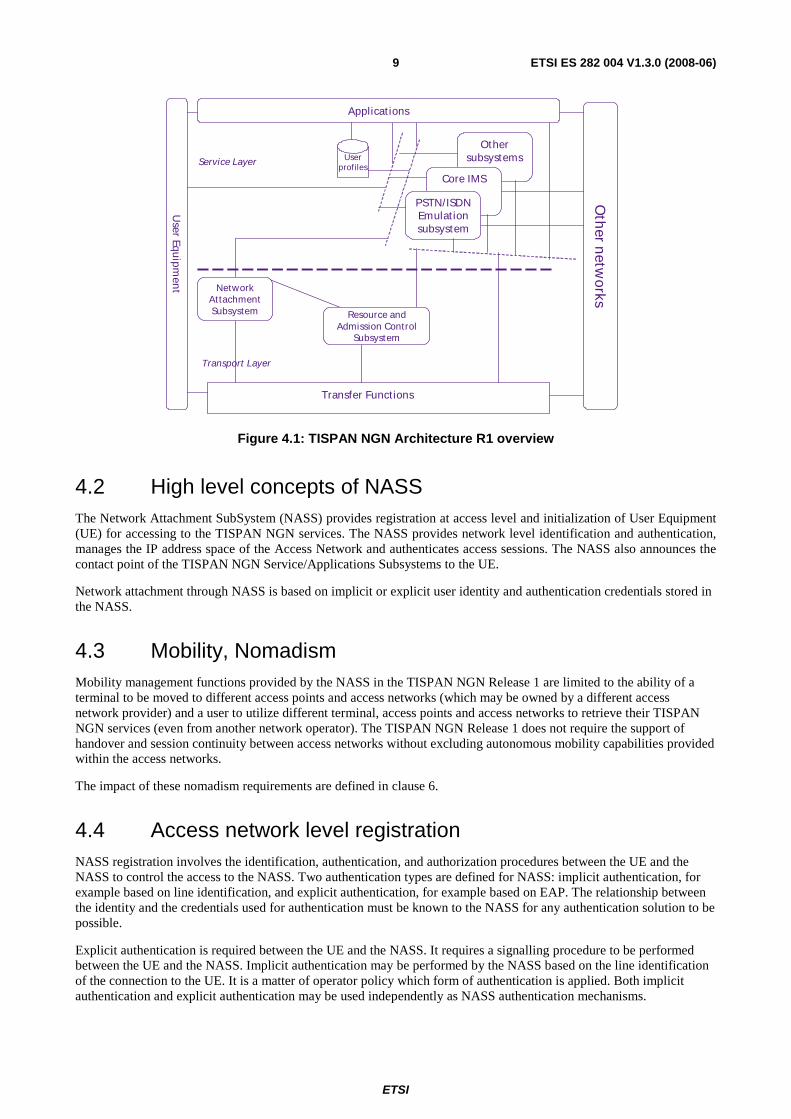
The location of this subsystem in the overall TISPAN architecture can be found in ES 282 001 [2] and is placed here for information in figure 4.1.
ETSI
ETSI ES 282 004 V1.3.0 (2008-06) 9
Oth
er netw
orks
Other subsystems
Core IMS
PSTN/ISDN Emulat ionsubsystem
User Equ
ipmen
t
Service Layer
Transport Layer
Transfer Functions
Resource and Admission Control
Subsystem
Network At tachment Subsystem
Applicat ions
Userprofiles
Figure 4.1: TISPAN NGN Architecture R1 overview
4.2 High level concepts of NASS The Network Attachment SubSystem (NASS) provides registration at access level and initialization of User Equipment (UE) for accessing to the TISPAN NGN services. The NASS provides network level identification and authentication, manages the IP address space of the Access Network and authenticates access sessions. The NASS also announces the contact point of the TISPAN NGN Service/Applications Subsystems to the UE.
Network attachment through NASS is based on implicit or explicit user identity and authentication credentials stored in the NASS.
4.3 Mobility, Nomadism Mobility management functions provided by the NASS in the TISPAN NGN Release 1 are limited to the ability of a terminal to be moved to different access points and access networks (which may be owned by a different access network provider) and a user to utilize different terminal, access points and access networks to retrieve their TISPAN NGN services (even from another network operator). The TISPAN NGN Release 1 does not require the support of handover and session continuity between access networks without excluding autonomous mobility capabilities provided within the access networks.
The impact of these nomadism requirements are defined in clause 6.
4.4 Access network level registration NASS registration involves the identification, authentication, and authorization procedures between the UE and the NASS to control the access to the NASS. Two authentication types are defined for NASS: implicit authentication, for example based on line identification, and explicit authentication, for example based on EAP. The relationship between the identity and the credentials used for authentication must be known to the NASS for any authentication solution to be possible.
Explicit authentication is required between the UE and the NASS. It requires a signalling procedure to be performed between the UE and the NASS. Implicit authentication may be performed by the NASS based on the line identification of the connection to the UE. It is a matter of operator policy which form of authentication is applied. Both implicit authentication and explicit authentication may be used independently as NASS authentication mechanisms.
ETSI
ETSI ES 282 004 V1.3.0 (2008-06) 10
4.4.1 Implicit authentication
Depending on the access network configuration, especially for wired broadband access networks, the implicit access authentication may rely only on an implicit authentication through physical or logic identity on the layer 2 (L2) transport layer. A UE can directly access to access network without an explicit authentication procedure.
A CNG shall be able to directly access an access network without an explicit authentication procedure. Which implicit authentication method applies depends on the operator policies.
4.4.1.1 Line authentication
Line authentication is a form of implicit authentication. Line authentication ensures that an access line is authenticated and can be accessed from the CNG. Line authentication shall be based on the activation of the L2 connection between the CNG and the access network.
Line authentication ensures that an access line is authenticated and can be accessed from the CNG. The line ID shall be used for line authentication. The operator's policy shall decide whether line authentication applies.
4.4.2 Explicit authentication
In case the CNG is a routing modem and the Customer Premises Network (CPN) is a private IP realm, authentication shall be initiated from the CNG. In case the CNG is a bridge, each UE shall authenticate with the NASS as the IP realm in the CPN is known to the Access Network (AN).
The relationship between the identity and the credentials used for authentication must be known to the NASS for any explicit authentication solution to be possible. The identity used for explicit authentication may depend on the authentication mechanism applied and on the access network which the UE is connected to. Two examples of these identities are:
• User identity and credentials.
• UE identity.
The type of explicit authentication mechanisms used shall depend on the access network configuration and on the operator policy.
4.4.3 CNG remote network configuration
This procedure is needed for the initialization of the CNGs accessing to the TISPAN NGN service subsystems.
4.4.4 TISPAN NGN Service/Applications Subsystems discovery
As part of the network registration process, the NASS shall have the possibility to announce the contact information of the TISPAN NGN Service/Applications Subsystems to the UE. In case the TISPAN NGN Subsystem is the IMS, the contact information provided by the NASS shall identify the P-CSCF.
The contact information provided by the NASS should either by in the form of the IP address of the contact point or in the form of the FQDN of the contact point (in which case the NASS provides the IP address of the DNS server that is able to resolve this FQDN into the IP address of the contact point).
Alternatively, the contact point to the TISPAN NGN Service/Applications Subsystems may be statically configured in the UE e.g. using fully qualified domain names (FQDN) and DNS resolution to retrieve the contact points IP addresses. This option applies in the non-roaming case.
ETSI
ETSI ES 282 004 V1.3.0 (2008-06) 11
5 Functional Architecture
5.1 Overview The Network Attachment SubSystem (NASS) comprises the following functional entities:
• Network Access Configuration Function (NACF).
• Access Management Function (AMF).
• Connectivity session Location and repository Function (CLF).
• User Access Authorization Function (UAAF).
• Profile Data Base Function (PDBF).
• CNG Configuration Function (CNGCF).
The NASS has interaction with the following TISPAN NGN functional entities:
• TISPAN Service control subsystems and applications.
• Resource Admission Control Subsystem (RACS).
• Access Relay Function (ARF).
• Customer Premises Equipment (CPE).
One or more functional entities may be mapped onto a single physical entity. If one functional entity is implemented by two physical entities, the interface between these physical entities is outside the scope of standardization.
Functional entities in the Network Attachment SubSystem (NASS) may be distributed over two administrative domains. See clause 6 for the impact of roaming on the distribution of NASS.
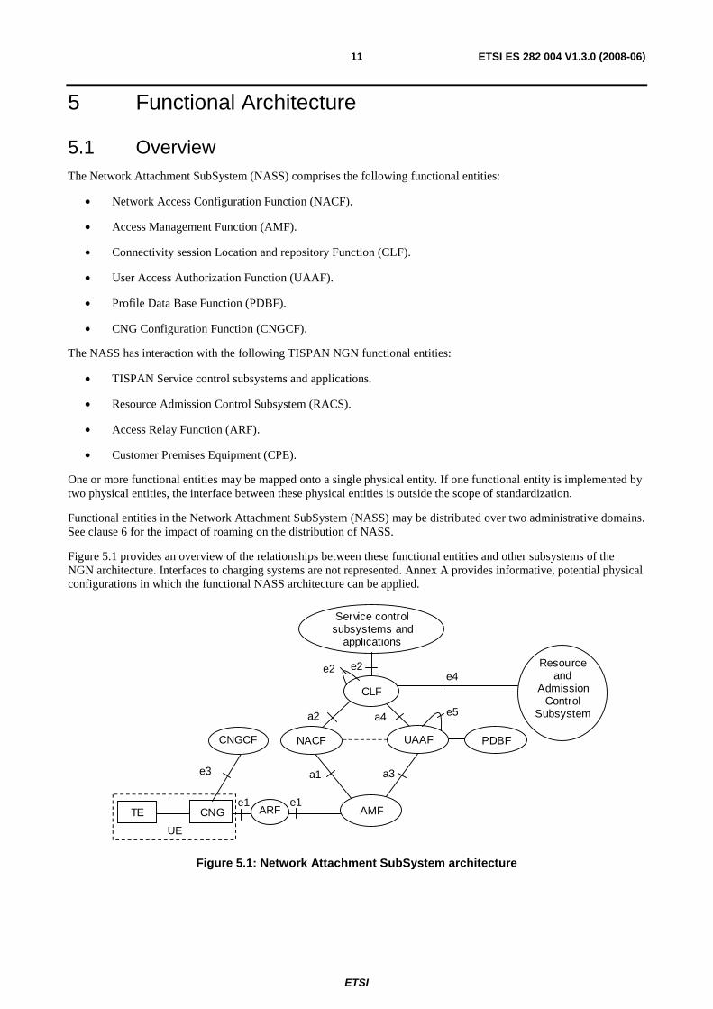
Figure 5.1 provides an overview of the relationships between these functional entities and other subsystems of the NGN architecture. Interfaces to charging systems are not represented. Annex A provides informative, potential physical configurations in which the functional NASS architecture can be applied.
a4
Service control subsystems and
applications
TE CNG
a3 a1
a2
e1
e2 e4
e3
Resource and
Admission Control
Subsystem
CLF
NACF CPECF
AMF
PDBF UAAF
ARF e1
e2
e5
CNGCF
UE
Figure 5.1: Network Attachment SubSystem architecture
ETSI
ETSI ES 282 004 V1.3.0 (2008-06) 12
5.2 Functional Entities
5.2.1 Network Access Configuration Function (NACF)
The Network Access Configuration Function (NACF) is responsible for the IP address allocation to the UE. It may also distribute other network configuration parameters such as address of DNS server(s), address of signalling proxies for specific protocols (e.g. address of the P-CSCF when accessing to the IMS).
The NACF should be able to provide to the UE an access network identifier. This information uniquely identifies the access network to which the UE is attached. With this information applications should be able to locate the CLF.
NOTE 1: The transport of the access identifier depends on extension in existing protocols (e.g. new DHCP option or usage of DHCP option 120). If NASS does not have the means to convey this parameter to the UE, this function will not be supported in this TISPAN Release.
NOTE 2: DHCP servers or RADIUS servers are typical implementations of the NACF.
5.2.2 Access Management Function (AMF)
The Access Management Function (AMF) translates network access requests issued by the UE. It forwards the requests for allocation of an IP address and possibly additional network configuration parameters to/from the NACF.
AMF forwards requests to the User Access Authorization Function (UAAF) to authenticate the user, authorize or deny the network access, and retrieve user-specific access configuration parameters.
In case PPP is applied, the AMF terminates the PPP connection and provides the inter-working with the interface to the network attachment subsystem e.g. using an AAA protocol (RADIUS or Diameter). The AMF acts as a RADIUS client if the UAAF is implemented in a RADIUS server (the AMF terminates the PPP and translates it to signalling on the a3 interface).
5.2.3 Connectivity session Location and repository Function (CLF)
The Connectivity session Location and repository Function (CLF) registers the association between the IP address allocated to the UE and related network location information provided by the NACF, i.e.: access transport equipment characteristics, line identifier (Logical Access ID), IP Edge identity, etc. The CLF registers the association between network location information received from the NACF and geographical location information. The CLF may also store the identity of the user / UE to which the IP address has been allocated (information received from the UAAF), as well as the user network QoS profile and user preferences regarding the privacy of location information. In case the CLF does not store the identity/profile of the user/UE, the CLF shall be able to retrieve this information from the UAAF. For detailed CLF information model see clause 5.2.3.1.
The CLF responds to location queries from service control subsystems and applications. The actual information delivered by the CLF may take various forms (e.g. network location, geographical coordinates, post mail address etc.), depending on agreements with the requestor and on user preferences regarding the privacy of its location.
NOTE 1: The retrieval by the CLF of geographical information from related user network location characteristics is outside of the scope of the present document.
NOTE 2: Geographical information may take several different forms depending on the access type and the application. The definition of this format shall also be lined up with OCG EMTEL who has decided that the LIF (Location Information Forum) is required in certain environments according to regulatory requirements. This data field is intend of placeholder for this information.
The CLF interfaces with the NACF to get the association between the IP address allocated by the NACF to the end user equipment and the Line ID.
The CLF registers also user network profile information (received from the UAAF at authentication) to make this profile information available to the RACS at authentication of the UE.
The CLF is able to correlate the information received from NACF and UAAF based on the Logical Access ID.
ETSI
ETSI ES 282 004 V1.3.0 (2008-06) 13
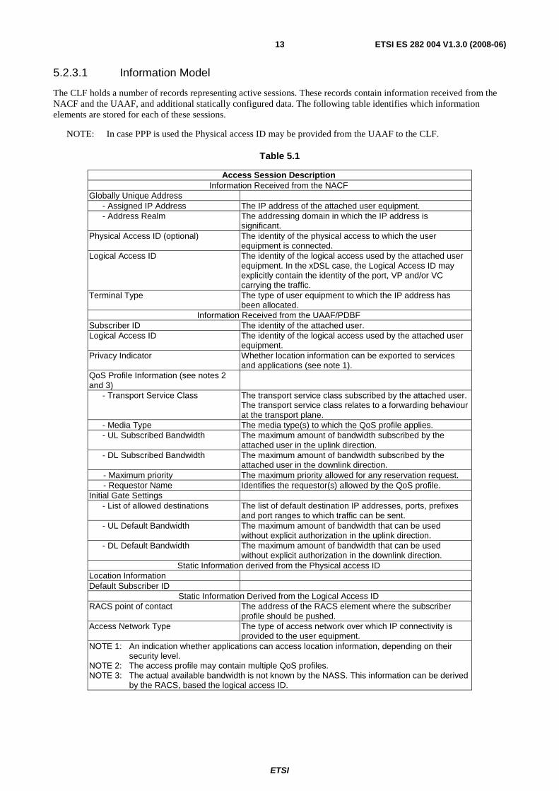
5.2.3.1 Information Model
The CLF holds a number of records representing active sessions. These records contain information received from the NACF and the UAAF, and additional statically configured data. The following table identifies which information elements are stored for each of these sessions.
NOTE: In case PPP is used the Physical access ID may be provided from the UAAF to the CLF.
Table 5.1
Access Session Description Information Received from the NACF
Globally Unique Address - Assigned IP Address The IP address of the attached user equipment. - Address Realm The addressing domain in which the IP address is
significant. Physical Access ID (optional) The identity of the physical access to which the user
equipment is connected. Logical Access ID The identity of the logical access used by the attached user
equipment. In the xDSL case, the Logical Access ID may explicitly contain the identity of the port, VP and/or VC carrying the traffic.
Terminal Type The type of user equipment to which the IP address has been allocated.
Information Received from the UAAF/PDBF Subscriber ID The identity of the attached user. Logical Access ID The identity of the logical access used by the attached user
equipment. Privacy Indicator Whether location information can be exported to services
and applications (see note 1). QoS Profile Information (see notes 2 and 3)
- Transport Service Class The transport service class subscribed by the attached user. The transport service class relates to a forwarding behaviour at the transport plane.
- Media Type The media type(s) to which the QoS profile applies. - UL Subscribed Bandwidth
The maximum amount of bandwidth subscribed by the attached user in the uplink direction.
- DL Subscribed Bandwidth
The maximum amount of bandwidth subscribed by the attached user in the downlink direction.
- Maximum priority The maximum priority allowed for any reservation request. - Requestor Name Identifies the requestor(s) allowed by the QoS profile. Initial Gate Settings - List of allowed destinations The list of default destination IP addresses, ports, prefixes
and port ranges to which traffic can be sent. - UL Default Bandwidth
The maximum amount of bandwidth that can be used without explicit authorization in the uplink direction.
- DL Default Bandwidth
The maximum amount of bandwidth that can be used without explicit authorization in the downlink direction.
Static Information derived from the Physical access ID Location Information Default Subscriber ID
Static Information Derived from the Logical Access ID RACS point of contact The address of the RACS element where the subscriber
profile should be pushed. Access Network Type The type of access network over which IP connectivity is
provided to the user equipment. NOTE 1: An indication whether applications can access location information, depending on their
security level. NOTE 2: The access profile may contain multiple QoS profiles. NOTE 3: The actual available bandwidth is not known by the NASS. This information can be derived
by the RACS, based the logical access ID.
ETSI
ETSI ES 282 004 V1.3.0 (2008-06) 14
Several records may contain the same physical access ID and/or logical access ID and/or subscriber ID, as a subscriber may establish more than one IP session, over the same or different logical access (e.g. ATM VC) using the same or different physical access. The CLF does not need to establish any link between such records, although it may do it for the purpose of optimizing its storage capacity.
5.2.4 User Access Authorization Function (UAAF)
The User Access Authorization Function (UAAF) performs user authentication, as well as authorization checking, based on user profiles, for network access. For each user, the UAAF retrieves authentication data and access authorization information from the user network profile information contained in the PDBF. The UAAF may also perform the collection of accounting data for each user authenticated by NASS.
The User Access Authorization Function (UAAF) can also act as a proxy. When acting as a proxy the UAAF can locate and communicate with the UAAF acting as server which contains the PDBF user authentication data. The UAAF proxy can forward access and authorization requests, as well as accounting messages, received from the AMF, to the UAAF acting as server. Responses received back in return from the UAAF acting as server will be returned to the AMF via the UAAF proxy.
In case PPP is applied, the AMF terminates the PPP and translates it to signalling on the a3 interface. The UAAF is assumed to be able to contact the NACF via an internal interface to obtain an IP address (UAAF and NACF are in the PPP case internal functions). The a1 reference point does not carry DHCP signalling, instead the a3 interface is used to give the IP configuration information to the AMF.
NOTE: Support of nomadicity entails a distinction between the user who requests access to the network and the user who owns the physical access through which the request is issued. Impact on this distinction on the UAAF requires further studies.
5.2.5 Profile DataBase Function (PDBF)
The Profile DataBase Function (PDBF) is the functional entity that contains user authentication data (user identity, list of supported authentication methods, key materials etc.) and information related to the required network access configuration: these data are called "user network profile".
In this release the interface between UAAF and PDBF is not specified, i.e. UAAF and PDBF are either co-located or connected by a non-standardized interface.
The PDBF can be co-located with the UPSF (described in ES 282 001 [2]).
5.2.6 CNG Configuration Function (CNGCF)
The CNGCF is used during initialization and update of the CNG. The CNGCF provides to the CNG with additional configuration information (e.g. configuration of a firewall internally in the CNG, QoS marking of IP packets etc.). This data differs from the network configuration data provided by the NACF.
5.2.7 Access Relay Function (ARF)
The NASS requires that the ARF is a relay between the CNG and the NASS that inserts local configuration information.
The functionality of ARF is described in ES 282 001 [2].
5.3 Internal Reference points
5.3.1 Reference Point AMF - NACF (a1)
This reference point allows the AMF to request the NACF for the allocation of an IP address to end user equipment as well as other network configuration parameters.
ETSI
ETSI ES 282 004 V1.3.0 (2008-06) 15
5.3.2 Reference Point NACF - CLF (a2)
This reference point allows the NACF to register in the CLF the association between the allocated IP address and the user identity as well as related location information (IP edge ID, Line ID).
The following information flows are used on the CLF to NACF interface:
• Bind Indication.
• Bind Acknowledgment.
• Unbind Indication.
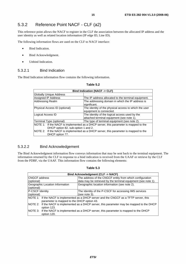
5.3.2.1 Bind Indication
The Bind Indication information flow contains the following information.
Table 5.2
Bind Indication (NACF -> CLF) Globally Unique Address Assigned IP Address The IP address allocated to the terminal equipment. Addressing Realm The addressing domain in which the IP address is
significant. Physical Access ID (optional) The identity of the physical access to which the user
equipment is connected. Logical Access ID The identity of the logical access used by the
attached terminal equipment (see note 1). Terminal Type (optional) The type of terminal equipment (see note 2). NOTE 1: If the NACF is implemented as a DHCP server, this parameter is mapped to the
DHCP option 82, sub-option 1 and 2. NOTE 2: If the NACF is implemented as a DHCP server, this parameter is mapped to the
DHCP option 77.
5.3.2.2 Bind Acknowledgement
The Bind Acknowledgment information flow conveys information that may be sent back to the terminal equipment. The information returned by the CLF in response to a bind indication is received from the UAAF or retrieve by the CLF from the PDBF, via the UAAF. This information flow contains the following elements:
Table 5.3
Bind Acknowledgment (CLF -> NACF) CNGCF address (optional)
The address of the CNGCF entity from which configuration data may be retrieved by the terminal equipment (see note 1).
Geographic Location Information (optional)
Geographic location information (see note 2).
P-CSCF Identity (optional)
The Identity of the P-CSCF for accessing IMS services (see note 3).
NOTE 1: If the NACF is implemented as a DHCP server and the CNGCF as a TFTP server, this parameter is mapped to the DHCP option 43.
NOTE 2: If the NACF is implemented as a DHCP server, this parameter may be mapped to the DHCP option 123.
NOTE 3: If the NACF is implemented as a DHCP server, this parameter is mapped to the DHCP option 120.
ETSI
ETSI ES 282 004 V1.3.0 (2008-06) 16
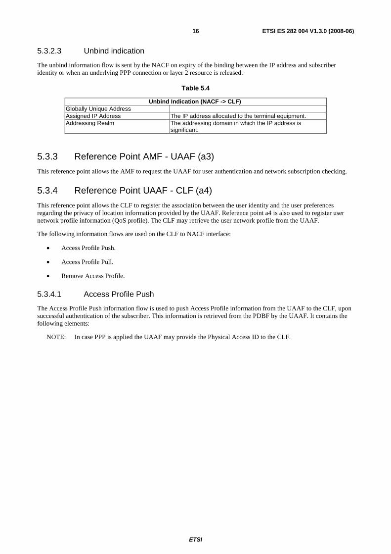
5.3.2.3 Unbind indication
The unbind information flow is sent by the NACF on expiry of the binding between the IP address and subscriber identity or when an underlying PPP connection or layer 2 resource is released.
Table 5.4
Unbind Indication (NACF -> CLF) Globally Unique Address Assigned IP Address The IP address allocated to the terminal equipment. Addressing Realm The addressing domain in which the IP address is
significant.
5.3.3 Reference Point AMF - UAAF (a3)
This reference point allows the AMF to request the UAAF for user authentication and network subscription checking.
5.3.4 Reference Point UAAF - CLF (a4)
This reference point allows the CLF to register the association between the user identity and the user preferences regarding the privacy of location information provided by the UAAF. Reference point a4 is also used to register user network profile information (QoS profile). The CLF may retrieve the user network profile from the UAAF.
The following information flows are used on the CLF to NACF interface:
• Access Profile Push.
• Access Profile Pull.
• Remove Access Profile.
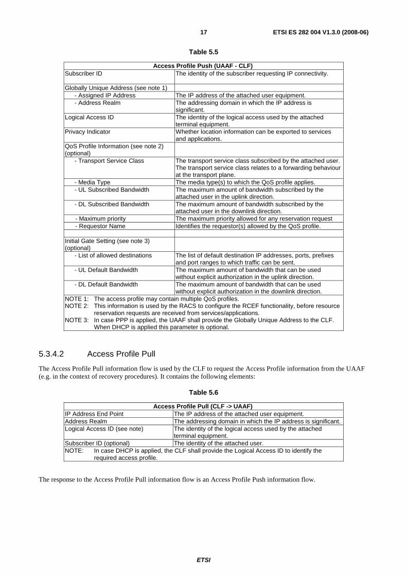
5.3.4.1 Access Profile Push
The Access Profile Push information flow is used to push Access Profile information from the UAAF to the CLF, upon successful authentication of the subscriber. This information is retrieved from the PDBF by the UAAF. It contains the following elements:
NOTE: In case PPP is applied the UAAF may provide the Physical Access ID to the CLF.
ETSI
ETSI ES 282 004 V1.3.0 (2008-06) 17
Table 5.5
Access Profile Push (UAAF - CLF) Subscriber ID The identity of the subscriber requesting IP connectivity.
Globally Unique Address (see note 1) - Assigned IP Address The IP address of the attached user equipment. - Address Realm The addressing domain in which the IP address is
significant. Logical Access ID The identity of the logical access used by the attached
terminal equipment. Privacy Indicator Whether location information can be exported to services
and applications. QoS Profile Information (see note 2) (optional)
- Transport Service Class The transport service class subscribed by the attached user. The transport service class relates to a forwarding behaviour at the transport plane.
- Media Type The media type(s) to which the QoS profile applies. - UL Subscribed Bandwidth
The maximum amount of bandwidth subscribed by the attached user in the uplink direction.
- DL Subscribed Bandwidth
The maximum amount of bandwidth subscribed by the attached user in the downlink direction.
- Maximum priority The maximum priority allowed for any reservation request - Requestor Name Identifies the requestor(s) allowed by the QoS profile. Initial Gate Setting (see note 3) (optional)
- List of allowed destinations The list of default destination IP addresses, ports, prefixes and port ranges to which traffic can be sent.
- UL Default Bandwidth
The maximum amount of bandwidth that can be used without explicit authorization in the uplink direction.
- DL Default Bandwidth
The maximum amount of bandwidth that can be used without explicit authorization in the downlink direction.
NOTE 1: The access profile may contain multiple QoS profiles. NOTE 2: This information is used by the RACS to configure the RCEF functionality, before resource
reservation requests are received from services/applications. NOTE 3: In case PPP is applied, the UAAF shall provide the Globally Unique Address to the CLF.
When DHCP is applied this parameter is optional.
5.3.4.2 Access Profile Pull
The Access Profile Pull information flow is used by the CLF to request the Access Profile information from the UAAF (e.g. in the context of recovery procedures). It contains the following elements:
Table 5.6
Access Profile Pull (CLF -> UAAF) IP Address End Point The IP address of the attached user equipment. Address Realm The addressing domain in which the IP address is significant. Logical Access ID (see note) The identity of the logical access used by the attached
terminal equipment. Subscriber ID (optional) The identity of the attached user. NOTE: In case DHCP is applied, the CLF shall provide the Logical Access ID to identify the
required access profile.
The response to the Access Profile Pull information flow is an Access Profile Push information flow.
ETSI
ETSI ES 282 004 V1.3.0 (2008-06) 18
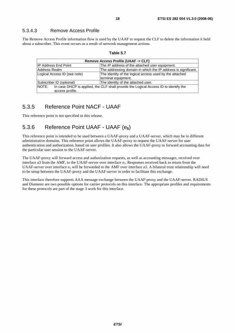
5.3.4.3 Remove Access Profile
The Remove Access Profile information flow is used by the UAAF to request the CLF to delete the information it held about a subscriber. This event occurs as a result of network management actions.
Table 5.7
Remove Access Profile (UAAF -> CLF) IP Address End Point The IP address of the attached user equipment. Address Realm The addressing domain in which the IP address is significant. Logical Access ID (see note) The identity of the logical access used by the attached
terminal equipment. Subscriber ID (optional) The identity of the attached user. NOTE: In case DHCP is applied, the CLF shall provide the Logical Access ID to identify the
access profile.
5.3.5 Reference Point NACF - UAAF
This reference point is not specified in this release.
5.3.6 Reference Point UAAF - UAAF (e5)
This reference point is intended to be used between a UAAF-proxy and a UAAF-server, which may be in different administrative domains. This reference point allows the UAAF-proxy to request the UAAF-server for user authentication and authorization, based on user profiles. It also allows the UAAF-proxy to forward accounting data for the particular user session to the UAAF-server.
The UAAF-proxy will forward access and authorization requests, as well as accounting messages, received over interface a3 from the AMF, to the UAAF-server over interface e5. Responses received back in return from the UAAF-server over interface e5 will be forwarded to the AMF over interface a3. A bilateral trust relationship will need to be setup between the UAAF-proxy and the UAAF-server in order to facilitate this exchange.
This interface therefore supports AAA message exchange between the UAAF-proxy and the UAAF-server. RADIUS and Diameter are two possible options for carrier protocols on this interface. The appropriate profiles and requirements for these protocols are part of the stage 3 work for this interface.
ETSI
ETSI ES 282 004 V1.3.0 (2008-06) 19
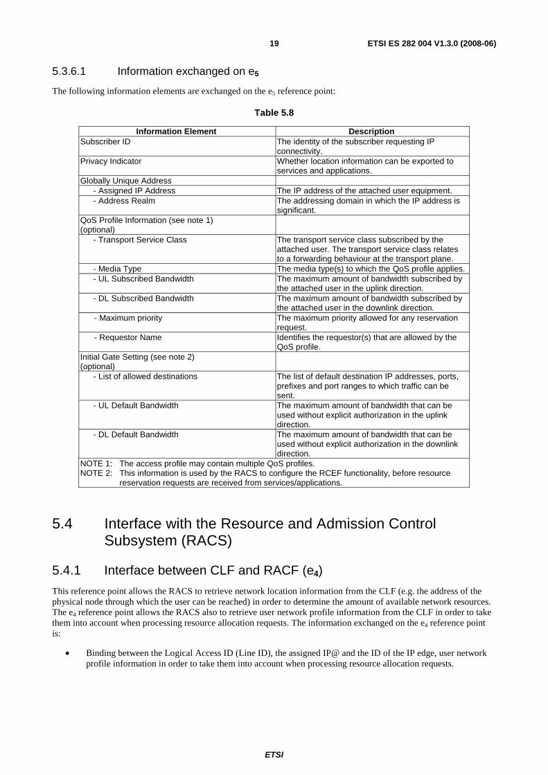
5.3.6.1 Information exchanged on e5
The following information elements are exchanged on the e5 reference point:
Table 5.8
Information Element Description Subscriber ID The identity of the subscriber requesting IP
connectivity. Privacy Indicator Whether location information can be exported to
services and applications. Globally Unique Address - Assigned IP Address The IP address of the attached user equipment. - Address Realm The addressing domain in which the IP address is
significant. QoS Profile Information (see note 1) (optional)
- Transport Service Class The transport service class subscribed by the attached user. The transport service class relates to a forwarding behaviour at the transport plane.
- Media Type The media type(s) to which the QoS profile applies. - UL Subscribed Bandwidth
The maximum amount of bandwidth subscribed by the attached user in the uplink direction.
- DL Subscribed Bandwidth
The maximum amount of bandwidth subscribed by the attached user in the downlink direction.
- Maximum priority The maximum priority allowed for any reservation request.
- Requestor Name Identifies the requestor(s) that are allowed by the QoS profile.
Initial Gate Setting (see note 2) (optional)
- List of allowed destinations The list of default destination IP addresses, ports, prefixes and port ranges to which traffic can be sent.
- UL Default Bandwidth
The maximum amount of bandwidth that can be used without explicit authorization in the uplink direction.
- DL Default Bandwidth
The maximum amount of bandwidth that can be used without explicit authorization in the downlink direction.
NOTE 1: The access profile may contain multiple QoS profiles. NOTE 2: This information is used by the RACS to configure the RCEF functionality, before resource
reservation requests are received from services/applications.
5.4 Interface with the Resource and Admission Control Subsystem (RACS)
5.4.1 Interface between CLF and RACF (e4)
This reference point allows the RACS to retrieve network location information from the CLF (e.g. the address of the physical node through which the user can be reached) in order to determine the amount of available network resources. The e4 reference point allows the RACS also to retrieve user network profile information from the CLF in order to take them into account when processing resource allocation requests. The information exchanged on the e4 reference point is:
• Binding between the Logical Access ID (Line ID), the assigned IP@ and the ID of the IP edge, user network profile information in order to take them into account when processing resource allocation requests.
ETSI
ETSI ES 282 004 V1.3.0 (2008-06) 20
The following information flows are used on the CLF to A-RACF interface:
• Access Profile Push.
• Access Profile Pull.
• IP Connectivity Release Indication.
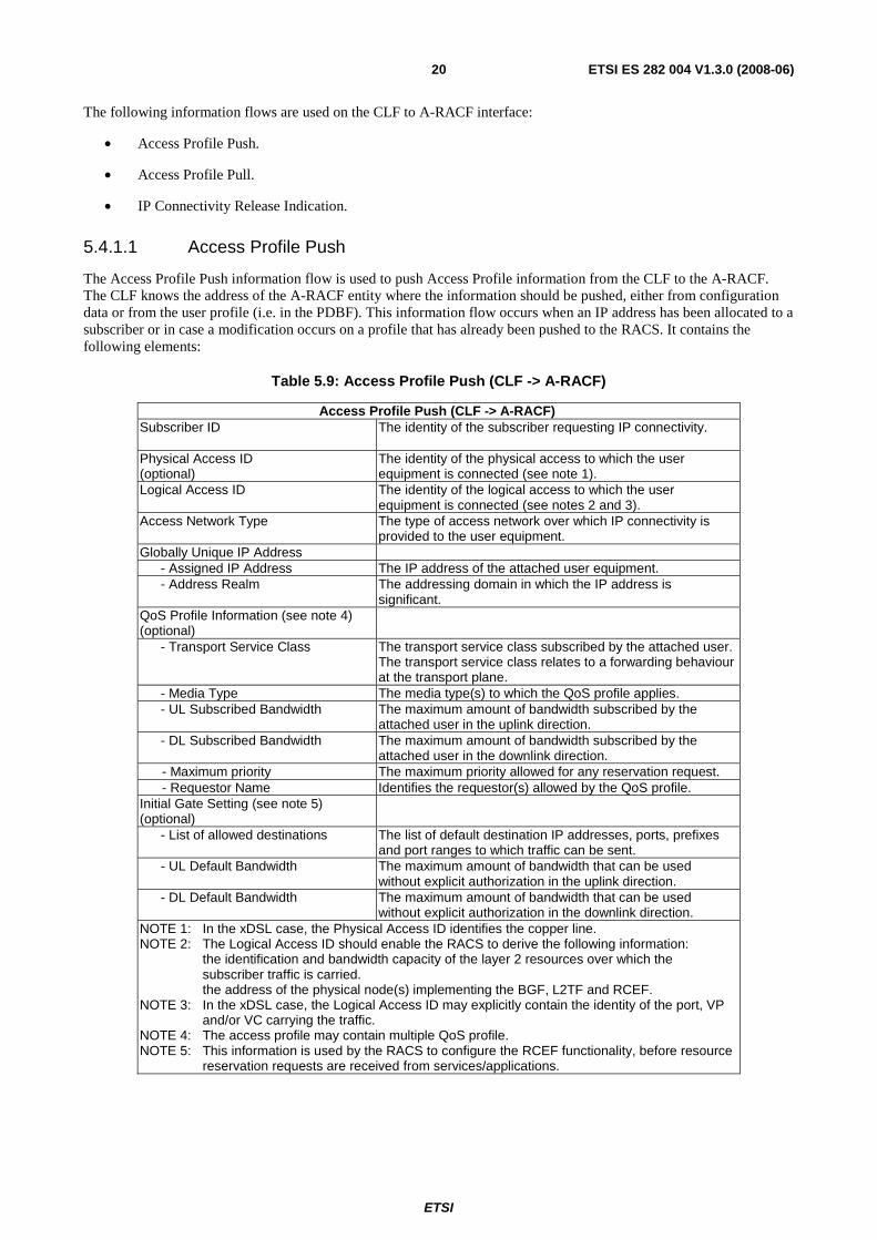
5.4.1.1 Access Profile Push
The Access Profile Push information flow is used to push Access Profile information from the CLF to the A-RACF. The CLF knows the address of the A-RACF entity where the information should be pushed, either from configuration data or from the user profile (i.e. in the PDBF). This information flow occurs when an IP address has been allocated to a subscriber or in case a modification occurs on a profile that has already been pushed to the RACS. It contains the following elements:
Table 5.9: Access Profile Push (CLF -> A-RACF)
Access Profile Push (CLF -> A-RACF) Subscriber ID The identity of the subscriber requesting IP connectivity.
Physical Access ID (optional)
The identity of the physical access to which the user equipment is connected (see note 1).
Logical Access ID The identity of the logical access to which the user equipment is connected (see notes 2 and 3).
Access Network Type The type of access network over which IP connectivity is provided to the user equipment.
Globally Unique IP Address - Assigned IP Address The IP address of the attached user equipment. - Address Realm The addressing domain in which the IP address is
significant. QoS Profile Information (see note 4) (optional)
- Transport Service Class The transport service class subscribed by the attached user. The transport service class relates to a forwarding behaviour at the transport plane.
- Media Type The media type(s) to which the QoS profile applies. - UL Subscribed Bandwidth
The maximum amount of bandwidth subscribed by the attached user in the uplink direction.
- DL Subscribed Bandwidth
The maximum amount of bandwidth subscribed by the attached user in the downlink direction.
- Maximum priority The maximum priority allowed for any reservation request. - Requestor Name Identifies the requestor(s) allowed by the QoS profile. Initial Gate Setting (see note 5) (optional)
- List of allowed destinations The list of default destination IP addresses, ports, prefixes and port ranges to which traffic can be sent.
- UL Default Bandwidth
The maximum amount of bandwidth that can be used without explicit authorization in the uplink direction.
- DL Default Bandwidth
The maximum amount of bandwidth that can be used without explicit authorization in the downlink direction.
NOTE 1: In the xDSL case, the Physical Access ID identifies the copper line. NOTE 2: The Logical Access ID should enable the RACS to derive the following information: the identification and bandwidth capacity of the layer 2 resources over which the
subscriber traffic is carried. the address of the physical node(s) implementing the BGF, L2TF and RCEF. NOTE 3: In the xDSL case, the Logical Access ID may explicitly contain the identity of the port, VP
and/or VC carrying the traffic. NOTE 4: The access profile may contain multiple QoS profile. NOTE 5: This information is used by the RACS to configure the RCEF functionality, before resource
reservation requests are received from services/applications.
ETSI
ETSI ES 282 004 V1.3.0 (2008-06) 21
5.4.1.2 Access Profile Pull
The Access Profile Pull information flow is used by the RACS to request the Access Profile information from the RACS (e.g. in the context of recovery procedures). It contains the following elements:
Table 5.10: Access Profile Pull (A-RACF -> CLF)
Access Profile Pull (A-RACF -> CLF) IP Address End Point The IP address of the attached user equipment. Address Realm The addressing domain in which the IP address is significant. Subscriber ID (optional) The identity of the attached user.
The response to the Access Profile Pull information flow is an Access Profile Push information flow.
5.4.1.3 IP Connectivity Release Indication
The IP Connectivity Release Indication information flow is used by the NASS to report loss of IP connectivity. This enables the RACS to remove the access profile from its internal data base. This event occurs in case the allocated IP address is released (e.g. DHCP leased timer expiry) or due to a release of the underlying layer 2 resources.
Table 5.11: IP Connectivity Release Indication (CLF -> A-RACF)
IP Connectivity Release Indication (CLF -> A-RACF) IP Address End Point The IP address of the attached user equipment. Address Realm The addressing domain in which the IP address is significant. Subscriber ID (optional) The identity of the attached user.
5.5 Interfaces between NASS and the application plane and service control subsystems
5.5.1 Interface between CLF and service control subsystems (e2)
This reference point enables applications and service control subsystems to retrieve from the CLF network location information. The primary parameter to retrieve the location information shall be the Assigned IP address allocated to the UE.
The form of location information that is provided by the CLF depends on the requestor.
The following information flows are used on the CLF to AF interface:
• Location Information Query.
• Location Information Response.
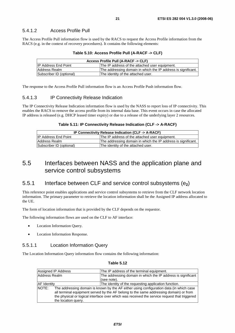
5.5.1.1 Location Information Query
The Location Information Query information flow contains the following information:
Table 5.12
Assigned IP Address The IP address of the terminal equipment. Address Realm The addressing domain in which the IP address is significant
(see note). AF Identity The identity of the requesting application function. NOTE: The addressing domain is known by the AF either using configuration data (in which case
all terminal equipment served by the AF belong to the same addressing domain) or from the physical or logical interface over which was received the service request that triggered the location query.
ETSI
ETSI ES 282 004 V1.3.0 (2008-06) 22
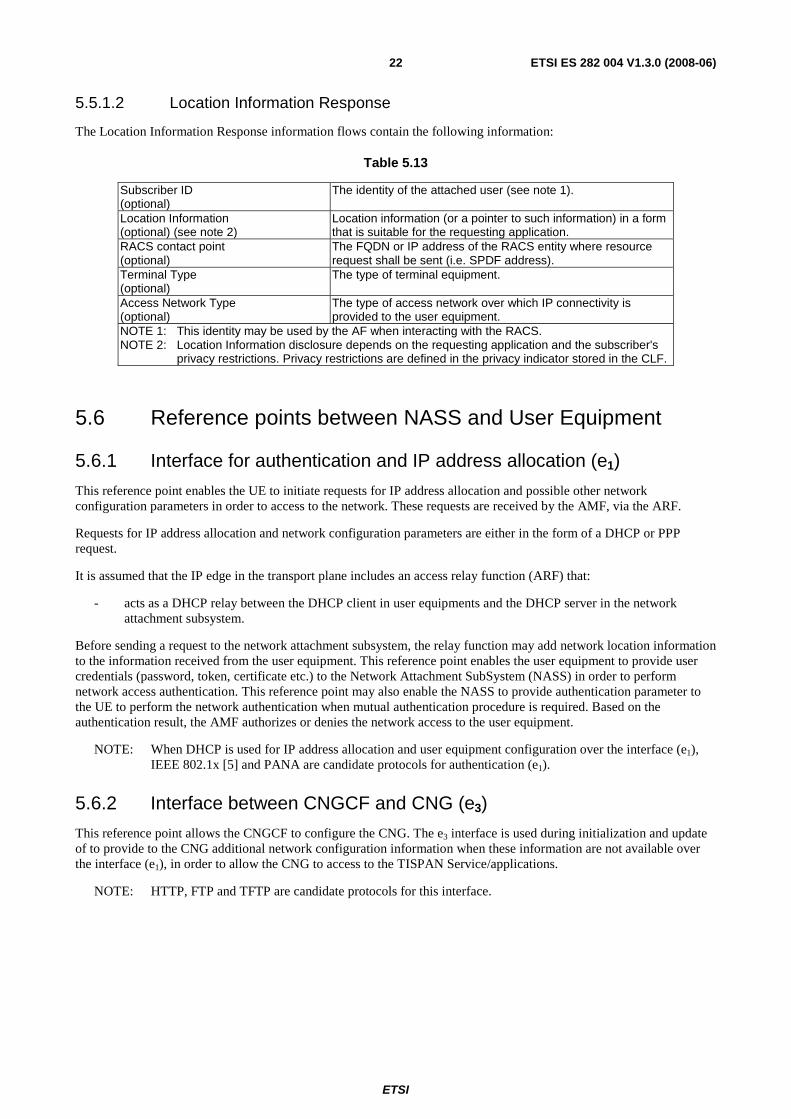
5.5.1.2 Location Information Response
The Location Information Response information flows contain the following information:
Table 5.13
Subscriber ID (optional)
The identity of the attached user (see note 1).
Location Information (optional) (see note 2)
Location information (or a pointer to such information) in a form that is suitable for the requesting application.
RACS contact point (optional)
The FQDN or IP address of the RACS entity where resource request shall be sent (i.e. SPDF address).
Terminal Type (optional)
The type of terminal equipment.
Access Network Type (optional)
The type of access network over which IP connectivity is provided to the user equipment.
NOTE 1: This identity may be used by the AF when interacting with the RACS. NOTE 2: Location Information disclosure depends on the requesting application and the subscriber's
privacy restrictions. Privacy restrictions are defined in the privacy indicator stored in the CLF.
5.6 Reference points between NASS and User Equipment
5.6.1 Interface for authentication and IP address allocation (e1)
This reference point enables the UE to initiate requests for IP address allocation and possible other network configuration parameters in order to access to the network. These requests are received by the AMF, via the ARF.
Requests for IP address allocation and network configuration parameters are either in the form of a DHCP or PPP request.
It is assumed that the IP edge in the transport plane includes an access relay function (ARF) that:
- acts as a DHCP relay between the DHCP client in user equipments and the DHCP server in the network attachment subsystem.
Before sending a request to the network attachment subsystem, the relay function may add network location information to the information received from the user equipment. This reference point enables the user equipment to provide user credentials (password, token, certificate etc.) to the Network Attachment SubSystem (NASS) in order to perform network access authentication. This reference point may also enable the NASS to provide authentication parameter to the UE to perform the network authentication when mutual authentication procedure is required. Based on the authentication result, the AMF authorizes or denies the network access to the user equipment.
NOTE: When DHCP is used for IP address allocation and user equipment configuration over the interface (e1), IEEE 802.1x [5] and PANA are candidate protocols for authentication (e1).
5.6.2 Interface between CNGCF and CNG (e3)
This reference point allows the CNGCF to configure the CNG. The e3 interface is used during initialization and update of to provide to the CNG additional network configuration information when these information are not available over the interface (e1), in order to allow the CNG to access to the TISPAN Service/applications.
NOTE: HTTP, FTP and TFTP are candidate protocols for this interface.
ETSI
ETSI ES 282 004 V1.3.0 (2008-06) 23
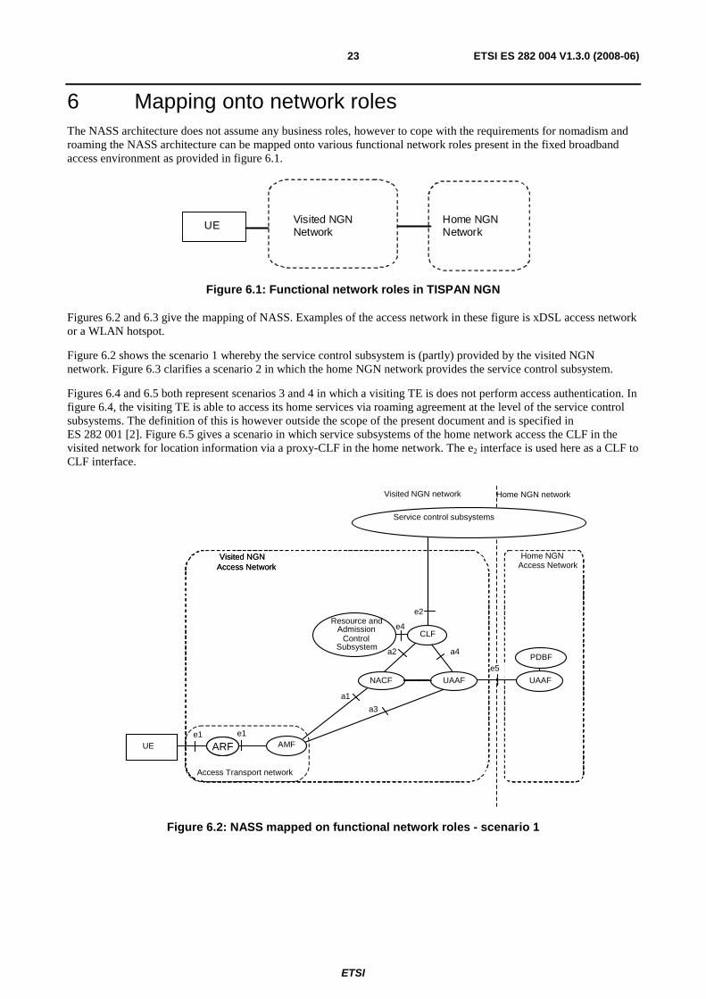
6 Mapping onto network roles The NASS architecture does not assume any business roles, however to cope with the requirements for nomadism and roaming the NASS architecture can be mapped onto various functional network roles present in the fixed broadband access environment as provided in figure 6.1.
UE Visited NGN Network
Home NGN Network
Figure 6.1: Functional network roles in TISPAN NGN
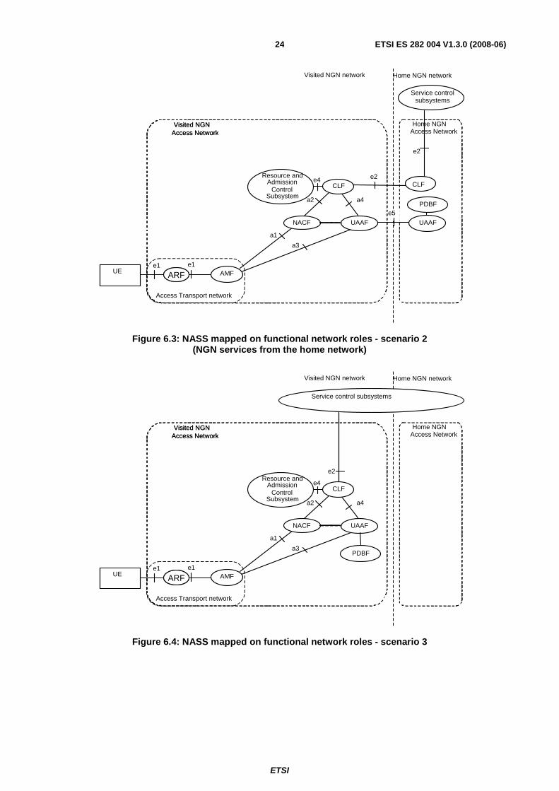
Figures 6.2 and 6.3 give the mapping of NASS. Examples of the access network in these figure is xDSL access network or a WLAN hotspot.
Figure 6.2 shows the scenario 1 whereby the service control subsystem is (partly) provided by the visited NGN network. Figure 6.3 clarifies a scenario 2 in which the home NGN network provides the service control subsystem.
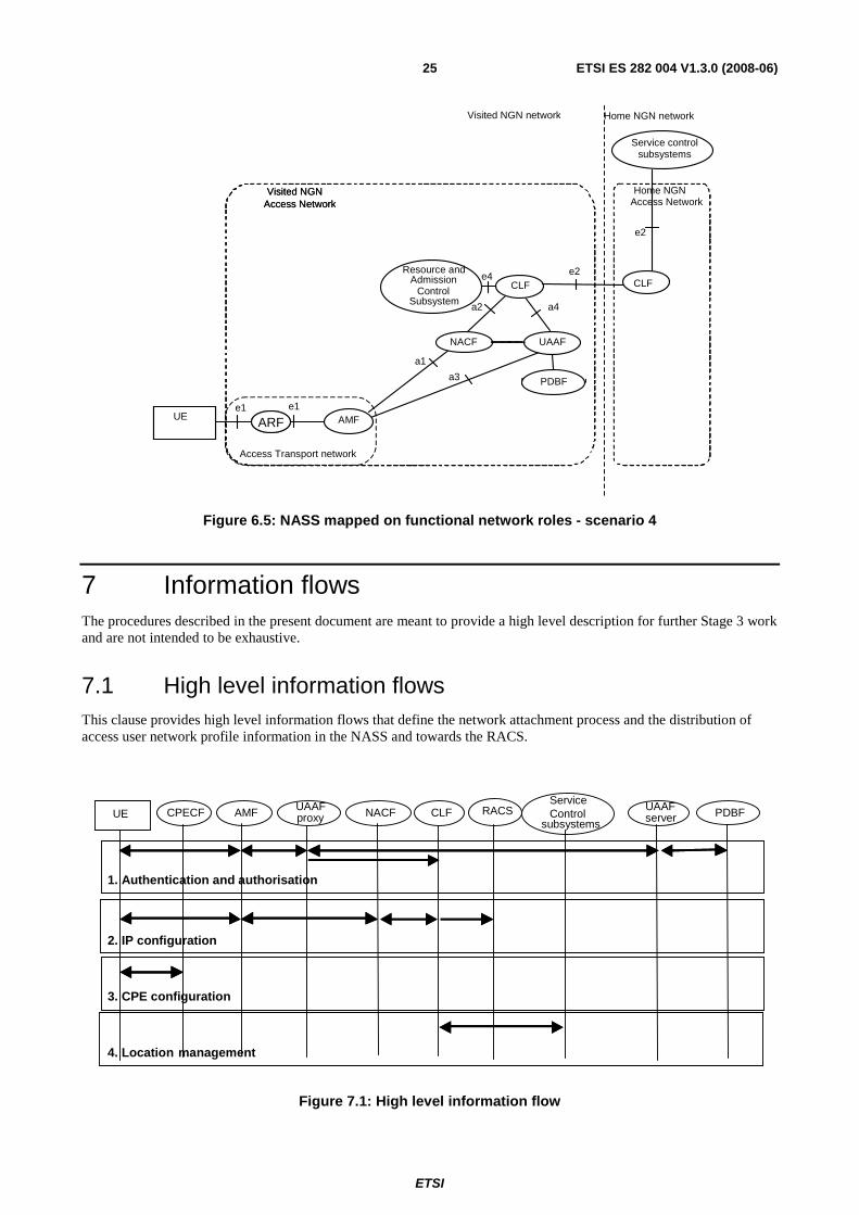
Figures 6.4 and 6.5 both represent scenarios 3 and 4 in which a visiting TE is does not perform access authentication. In figure 6.4, the visiting TE is able to access its home services via roaming agreement at the level of the service control subsystems. The definition of this is however outside the scope of the present document and is specified in ES 282 001 [2]. Figure 6.5 gives a scenario in which service subsystems of the home network access the CLF in the visited network for location information via a proxy-CLF in the home network. The e2 interface is used here as a CLF to CLF interface.
Home NGN Access Network
UAAF
Visited NGN Access Network
PDBF
CPE (CNG/TE)
e5
ARF
a4
Service control subsystems
a3 a1
a2
e1
e2 e4 Resource and
Admission Control
Subsystem CLF
NACF
AMF
UAAF
Home NGN Access Network
UAAF
Visited NGN Access Network
PDBF
UE
e5
ARF
Visited NGN network Home NGN network
Access Transport network
e1
Figure 6.2: NASS mapped on functional network roles - scenario 1
ETSI
ETSI ES 282 004 V1.3.0 (2008-06) 24
Home NGN Access Network
UAAF
Visited NGN Access Network
PDBF
CPE (CNG/TE)
e5
ARF
a4
Service control subsystems
a3 a1
a2
e1
e2
e4 Resource and Admission
Control Subsystem
CLF
NACF
AMF
UAAF
Home NGN Access Network
UAAF
Visited NGN Access Network
PDBF
UE
e5
ARF
Visited NGN network Home NGN network
Access Transport network
e1
CLF e2
Figure 6.3: NASS mapped on functional network roles - scenario 2 (NGN services from the home network)
Home NGN Access Network
UAAF
Visited NGN Access Network
PDBF
CPE (CNG/TE)
ARF
a4
Service control subsystems
a3 a1
a2
e1
e2 e4 Resource and
Admission Control
Subsystem CLF
NACF
AMF
UAAF
Home NGN Access Network
Visited NGN Access Network
PDBF
UE ARF
Visited NGN network Home NGN network
Access Transport network
e1
Figure 6.4: NASS mapped on functional network roles - scenario 3
ETSI
ETSI ES 282 004 V1.3.0 (2008-06) 25
Home NGN Access Network
UAAF
Visited NGN Access Network
PDBF
CPE (CNG/TE) ARF
a4
Service control subsystems
a3 a1
a2
e1
e2
e4 Resource and Admission
Control Subsystem
CLF
NACF
AMF
UAAF
Home NGN Access Network
Visited NGN Access Network
PDBF
UE ARF
Visited NGN network Home NGN network
Access Transport network
e1
CLF e2
Figure 6.5: NASS mapped on functional network roles - scenario 4
7 Information flows The procedures described in the present document are meant to provide a high level description for further Stage 3 work and are not intended to be exhaustive.
7.1 High level information flows This clause provides high level information flows that define the network attachment process and the distribution of access user network profile information in the NASS and towards the RACS.
Service Control
subsystems RACS CLF NACF CPECF AMF UAAF
proxy UAAF server PDBF UE
1. Authentication and authorisation
2. IP configuration
4. Location management
3. CPE configuration
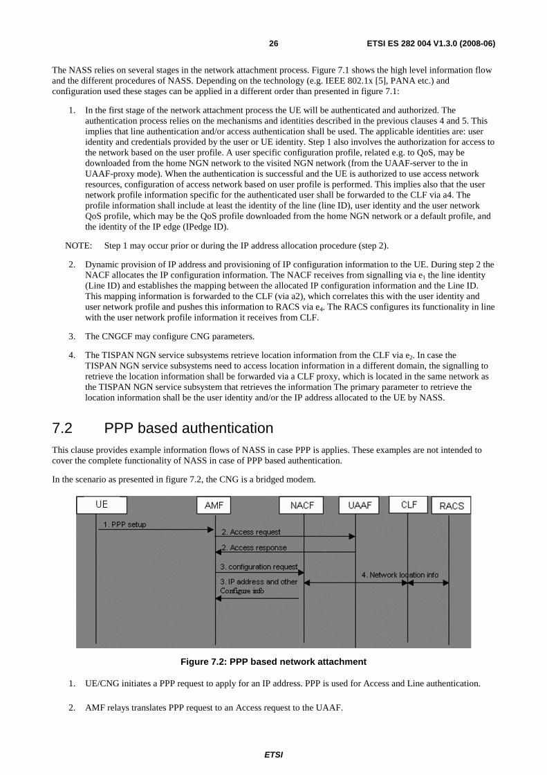
Figure 7.1: High level information flow
ETSI
ETSI ES 282 004 V1.3.0 (2008-06) 26
The NASS relies on several stages in the network attachment process. Figure 7.1 shows the high level information flow and the different procedures of NASS. Depending on the technology (e.g. IEEE 802.1x [5], PANA etc.) and configuration used these stages can be applied in a different order than presented in figure 7.1:
1. In the first stage of the network attachment process the UE will be authenticated and authorized. The authentication process relies on the mechanisms and identities described in the previous clauses 4 and 5. This implies that line authentication and/or access authentication shall be used. The applicable identities are: user identity and credentials provided by the user or UE identity. Step 1 also involves the authorization for access to the network based on the user profile. A user specific configuration profile, related e.g. to QoS, may be downloaded from the home NGN network to the visited NGN network (from the UAAF-server to the in UAAF-proxy mode). When the authentication is successful and the UE is authorized to use access network resources, configuration of access network based on user profile is performed. This implies also that the user network profile information specific for the authenticated user shall be forwarded to the CLF via a4. The profile information shall include at least the identity of the line (line ID), user identity and the user network QoS profile, which may be the QoS profile downloaded from the home NGN network or a default profile, and the identity of the IP edge (IPedge ID).
NOTE: Step 1 may occur prior or during the IP address allocation procedure (step 2).
2. Dynamic provision of IP address and provisioning of IP configuration information to the UE. During step 2 the NACF allocates the IP configuration information. The NACF receives from signalling via e1 the line identity (Line ID) and establishes the mapping between the allocated IP configuration information and the Line ID. This mapping information is forwarded to the CLF (via a2), which correlates this with the user identity and user network profile and pushes this information to RACS via e4. The RACS configures its functionality in line with the user network profile information it receives from CLF.
3. The CNGCF may configure CNG parameters.
4. The TISPAN NGN service subsystems retrieve location information from the CLF via e2. In case the TISPAN NGN service subsystems need to access location information in a different domain, the signalling to retrieve the location information shall be forwarded via a CLF proxy, which is located in the same network as the TISPAN NGN service subsystem that retrieves the information The primary parameter to retrieve the location information shall be the user identity and/or the IP address allocated to the UE by NASS.
7.2 PPP based authentication This clause provides example information flows of NASS in case PPP is applies. These examples are not intended to cover the complete functionality of NASS in case of PPP based authentication.
In the scenario as presented in figure 7.2, the CNG is a bridged modem.
Figure 7.2: PPP based network attachment
1. UE/CNG initiates a PPP request to apply for an IP address. PPP is used for Access and Line authentication.
2. AMF relays translates PPP request to an Access request to the UAAF.
ETSI
ETSI ES 282 004 V1.3.0 (2008-06) 27
3. AMF sends the configuration request to NACF to obtain IP address and other parameters including the IP address of a TISPAN NGN Service/Applications Subsystems (e.g. P-CSCF).
4. NACF sends to the CLF the binding information of allocated IP address, Line ID and IP edge ID. The CLF pushes the binding information to the RACS via the e4 interface.
NOTE: It remains to be checked whether this scenario poses constraints on the support of nomadicity.
7.3 DHCP mode This clause provides example information flows of NASS in case of DHCP is used. These examples are not intended to cover the complete functionality of NASS in case of DHCP mode.
The CNG is a bridged modem.
UE AMF NACF UAAF
1. 802.1x/PANA/Implicit authentication
4. DHCP request andoption 120 (RFC 3361) 5. IP address
allocation
2. Access request (no IP address)
7. DHCP response (IP address and P-CSCF address)
CLF
3. Netw ork location info
6. Netw ork location info
RACS
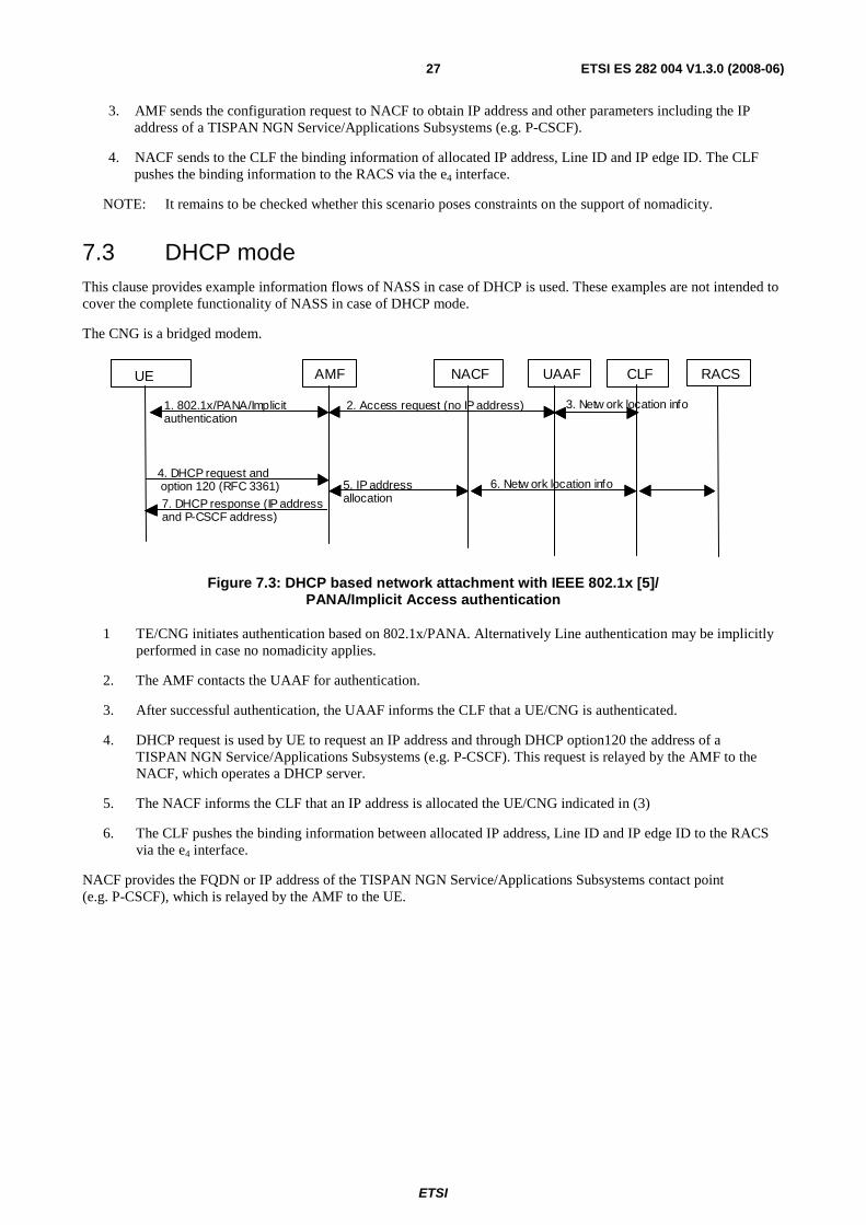
Figure 7.3: DHCP based network attachment with IEEE 802.1x [5]/ PANA/Implicit Access authentication
1 TE/CNG initiates authentication based on 802.1x/PANA. Alternatively Line authentication may be implicitly performed in case no nomadicity applies.
2. The AMF contacts the UAAF for authentication.
3. After successful authentication, the UAAF informs the CLF that a UE/CNG is authenticated.
4. DHCP request is used by UE to request an IP address and through DHCP option120 the address of a TISPAN NGN Service/Applications Subsystems (e.g. P-CSCF). This request is relayed by the AMF to the NACF, which operates a DHCP server.
5. The NACF informs the CLF that an IP address is allocated the UE/CNG indicated in (3)
6. The CLF pushes the binding information between allocated IP address, Line ID and IP edge ID to the RACS via the e4 interface.
NACF provides the FQDN or IP address of the TISPAN NGN Service/Applications Subsystems contact point (e.g. P-CSCF), which is relayed by the AMF to the UE.
ETSI
ETSI ES 282 004 V1.3.0 (2008-06) 28
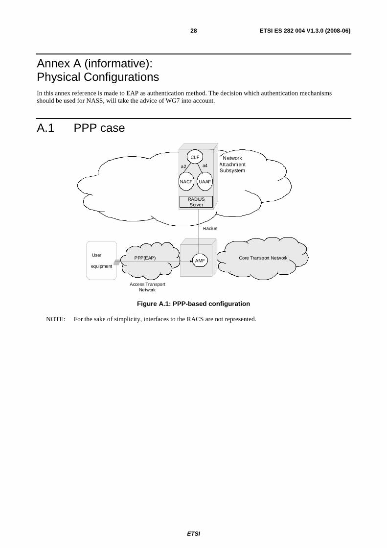
Annex A (informative): Physical Configurations In this annex reference is made to EAP as authentication method. The decision which authentication mechanisms should be used for NASS, will take the advice of WG7 into account.
A.1 PPP case
User
equipment
Network Attachment Subsystem
Radius
Core Transport Network
Access Transport Network
AMF PPP(EAP)
RADIUS Server
NACF UAAF
CLF a4 a2
Figure A.1: PPP-based configuration
NOTE: For the sake of simplicity, interfaces to the RACS are not represented.
ETSI
ETSI ES 282 004 V1.3.0 (2008-06) 29
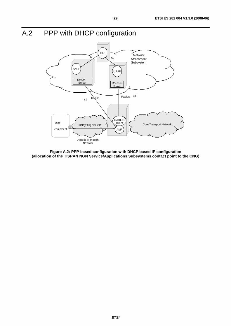
A.2 PPP with DHCP configuration
User equipment
Network Attachment Subsystem
Radius
Core Transport Network
Access Transport Network
AMF
RADIUS Client
PPP(EAP) / DHCP
RADIUS Proxy
DHCP Server
NACF UAAF
CLF
a1
a4 a2
DHCP a3
Figure A.2: PPP-based configuration with DHCP based IP configuration (allocation of the TISPAN NGN Service/Applications Subsystems contact point to the CNG)
ETSI
ETSI ES 282 004 V1.3.0 (2008-06) 30
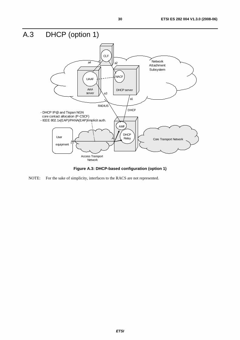
A.3 DHCP (option 1)
User
equipment Core Transport Network
Access Transport Network
DHCP Relay
- DHCP IP@ and Tispan NGN core contact allocation (P-CSCF) - IEEE 802.1x(EAP)/PANA(EAP)/implicit auth.
Network Attachment Subsystem
DHCP
AAA server
UAAF
DHCP server
NACF
AMF
CLF a2
a3
a4
RADIUS a1
Figure A.3: DHCP-based configuration (option 1)
NOTE: For the sake of simplicity, interfaces to the RACS are not represented.
ETSI
ETSI ES 282 004 V1.3.0 (2008-06) 31
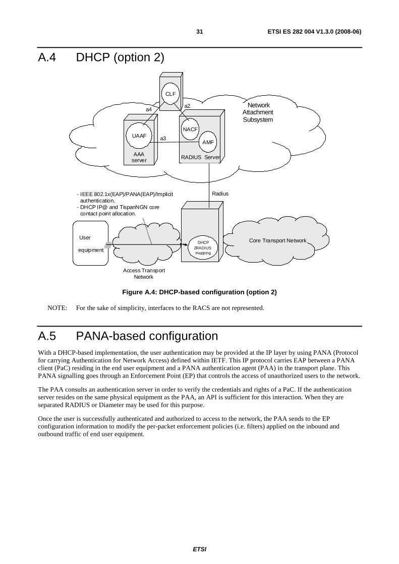
A.4 DHCP (option 2)
User
equipment Core Transport Network
Access Transport Network
- IEEE 802.1x(EAP)/PANA(EAP)/Implicit authentication. - DHCP IP@ and TispanNGN core contact point allocation.
Network Attachment Subsystem
Radius
AAA server
UAAF
RADIUS Server
NACF
AMF
CLF
a2
a3
DHCP 2RADIUS mapping
a4
Figure A.4: DHCP-based configuration (option 2)
NOTE: For the sake of simplicity, interfaces to the RACS are not represented.
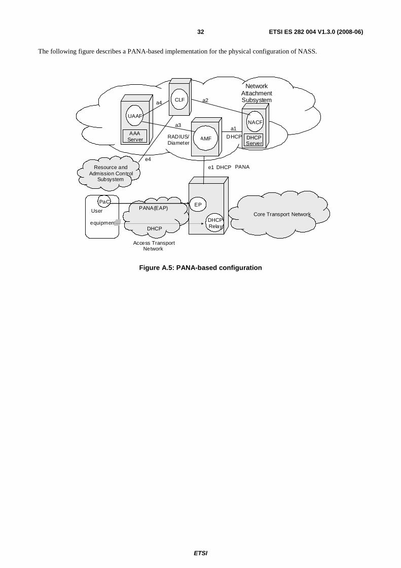
A.5 PANA-based configuration With a DHCP-based implementation, the user authentication may be provided at the IP layer by using PANA (Protocol for carrying Authentication for Network Access) defined within IETF. This IP protocol carries EAP between a PANA client (PaC) residing in the end user equipment and a PANA authentication agent (PAA) in the transport plane. This PANA signalling goes through an Enforcement Point (EP) that controls the access of unauthorized users to the network.
The PAA consults an authentication server in order to verify the credentials and rights of a PaC. If the authentication server resides on the same physical equipment as the PAA, an API is sufficient for this interaction. When they are separated RADIUS or Diameter may be used for this purpose.
Once the user is successfully authenticated and authorized to access to the network, the PAA sends to the EP configuration information to modify the per-packet enforcement policies (i.e. filters) applied on the inbound and outbound traffic of end user equipment.
ETSI
ETSI ES 282 004 V1.3.0 (2008-06) 32
The following figure describes a PANA-based implementation for the physical configuration of NASS.
User
equipment
Network Attachment Subsystem
PANA
Core Transport Network
Access Transport Network
EP
DHCP
AMF AAA
Server
UAAF
CLF a4
a1 NACF
DHCP Server
DHCP Relay
PaC PANA(EAP)
DHCP
DHCP RADIUS/ Diameter
Resource and Admission Control
Subsystem
e1
a2
e4
a3
Figure A.5: PANA-based configuration

ETSI
ETSI ES 282 004 V1.3.0 (2008-06) 33
Annex B (informative): Bibliography
• ETSI TR 180 001: "Telecommunications and Internet converged Services and Protocols for Advanced Networking (TISPAN); NGN Release 1; Release definition".
• ETSI ES 282 007: "Telecommunications and Internet converged Services and Protocols for Advanced Networking (TISPAN); IP Multimedia Subsystem (IMS); Functional architecture".
• IETF RFC 4058: "Protocol for Carrying Authentication for Network Access (PANA) Requirements".

ETSI
ETSI ES 282 004 V1.3.0 (2008-06) 34
History
Document history
V1.1.1 June 2006 Publication
V1.3.0 March 2008 Membership Approval Procedure MV 20080502: 2008-03-04 to 2008-05-02
V1.3.0 June 2008 Publication