ertms - etcs - uic · ertms - etcs european rail traffic management system european train control...
TRANSCRIPT
ERTMS - ETCSERTMS - ETCSEuropean Rail Traffic Management SystemEuropean Rail Traffic Management System
European Train Control SystemEuropean Train Control System
Training in High Speed Systems – July, 6th 2004
2
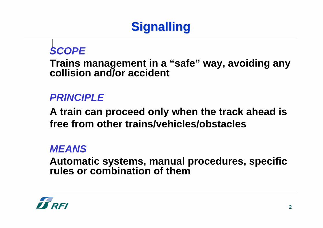
SignallingSignalling
SCOPETrains management in a “safe” way, avoiding anycollision and/or accident
PRINCIPLEA train can proceed only when the track ahead isfree from other trains/vehicles/obstacles
MEANSAutomatic systems, manual procedures, specificrules or combination of them
3
SignallingSignalling SystemsSystems forfor HS HS lineslines
UIC Fiche 734: Adaptation of safetyinstallations to high-speed requirements (Jan. 2004) defines the minimum technicalre-quirements in respect of safetyinstallations for high-speed lines, asdictated by the constraints of operating,rolling stock and fixed installations
4
04ATR654
ATB/ATB-NG
AWS
TVM/KVB
ASFA/LZB
EBICAB 700
BACC/RSDD
TBL
SIGNUM
EVM
INDUSI/LZB
KHP
INDUSI/LZB/SELCAB
EBICAB 900
ZUB 123
EBICAB 700/L 10000
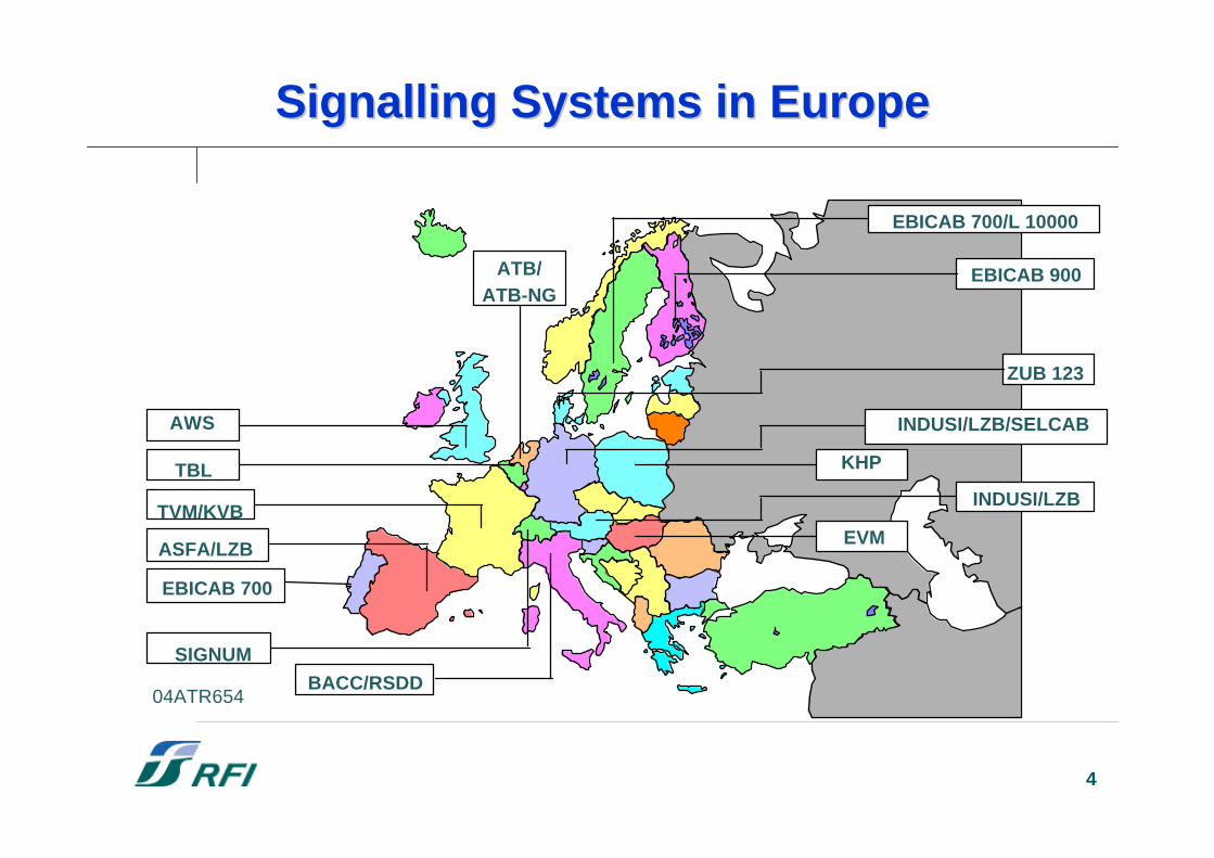
Signalling Systems in Europe Signalling Systems in Europe
5
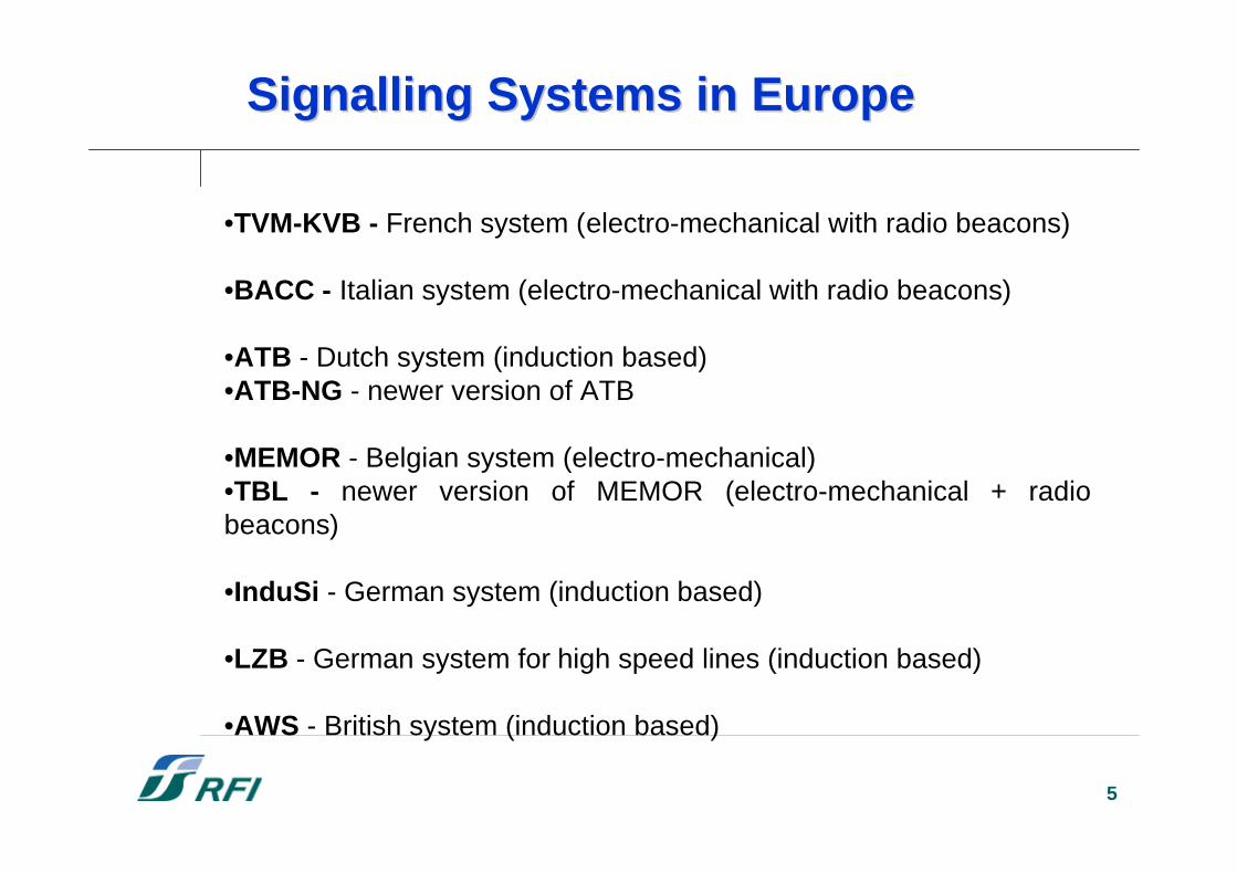
•TVM-KVB - French system (electro-mechanical with radio beacons)
•BACC - Italian system (electro-mechanical with radio beacons)
•ATB - Dutch system (induction based)•ATB-NG - newer version of ATB
•MEMOR - Belgian system (electro-mechanical)•TBL - newer version of MEMOR (electro-mechanical + radiobeacons)
•InduSi - German system (induction based)
•LZB - German system for high speed lines (induction based)
•AWS - British system (induction based)
Signalling Systems in EuropeSignalling Systems in Europe
6
The Germany LZB The Germany LZB
The LZB (LinienZugBeeinflussung)literally means Linear Train Control, asopposed to using fixed signals [SpotwiseTrain Control], since communicaton to thetrain takes place only at certain spots, i.e.the signal locations).That would be the Indusi system.
7
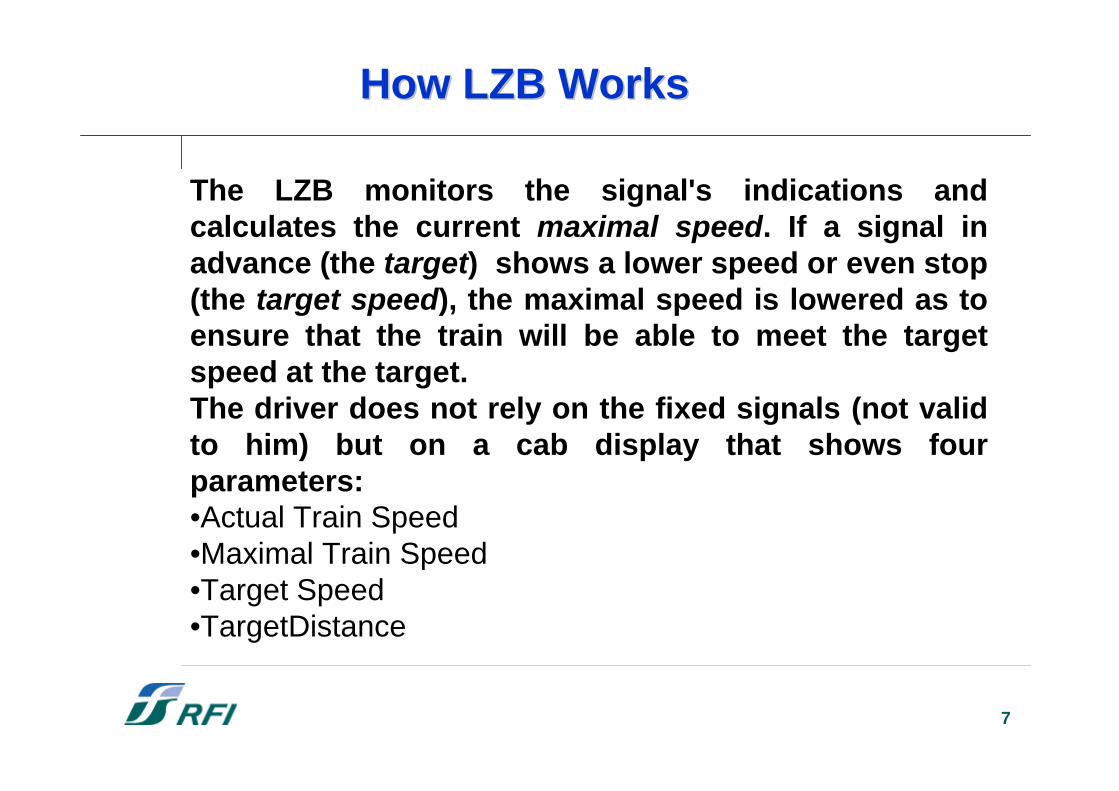
The LZB monitors the signal's indications andcalculates the current maximal speed. If a signal inadvance (the target) shows a lower speed or even stop(the target speed), the maximal speed is lowered as toensure that the train will be able to meet the targetspeed at the target.The driver does not rely on the fixed signals (not validto him) but on a cab display that shows fourparameters:•Actual Train Speed •Maximal Train Speed •Target Speed •TargetDistance
How LZB WorksHow LZB Works
8
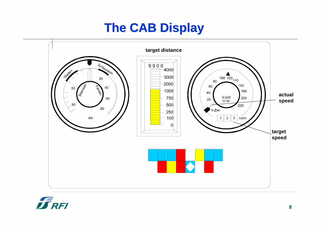
target distance
actualspeed
targetspeed
The CAB DisplayThe CAB Display
9
The French TVM-KVBThe French TVM-KVB
TVM is a fixed block system: the track issubdivided into fixed segments each ofwhich has a particular state. Only onetrain may occupy any block at one timeunder normal operation.
On high speed lines TVM is permissive:a train may proceed at reduced speed(O.S. mode) after a stop.
10
Two sub-systems: one on ground one on board.
On ground SS:•controls stretches of track about 15 km long;•is linked to the line's centralized traffic control center•controls ten blocks of track, each with its own track circuit.Signaling information is encoded in AC signals (a 27-bit digital word)which are fed into the rails of each block indicating Speed, Gradient,Block Length, Network CodeIn addition, single instructions can be sent by inductive loops on therail, to indicate «actions» (Entry or exit from a high speed line, Raisingor lowering pantographs, Switching supply voltages,...)
On board SS:•reads (at speeds up to 400 km/h) the codes and continuouslysupervises the train running
How TVM WorksHow TVM Works
11
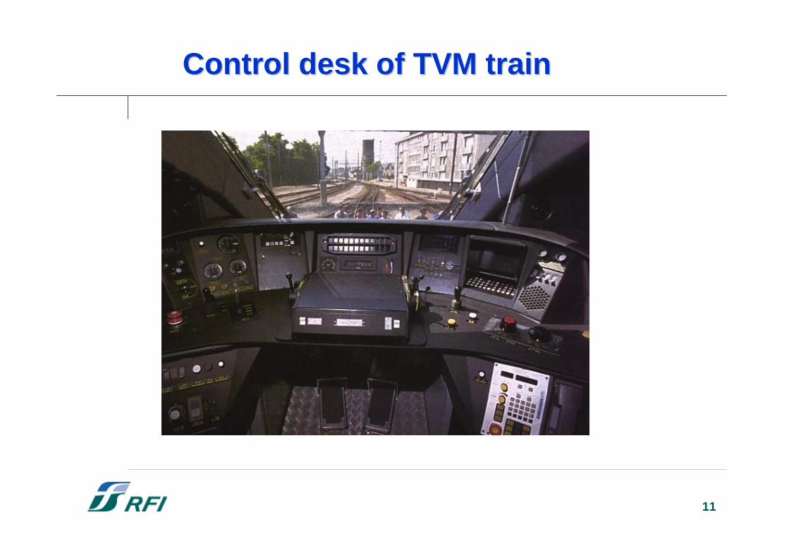
Control desk of TVM Control desk of TVM traintrain
12
The Italian BACCThe Italian BACC
BACC is also a fixed block system: thetrack is subdivided into fixed segments andonly one train may occupy any segment atone time under normal operation.
BACC is a permissive system: a train mayproceed at reduced speed (O.S. mode)after a stop.
13
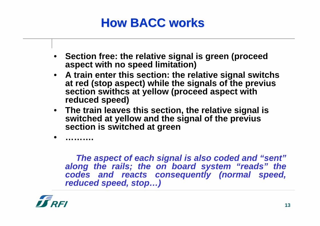
How BACC worksHow BACC works
• Section free: the relative signal is green (proceedaspect with no speed limitation)
• A train enter this section: the relative signal switchsat red (stop aspect) while the signals of the previussection swithcs at yellow (proceed aspect withreduced speed)
• The train leaves this section, the relative signal isswitched at yellow and the signal of the previussection is switched at green
• ……….
The aspect of each signal is also coded and “sent”along the rails; the on board system “reads” thecodes and reacts consequently (normal speed,reduced speed, stop…)
14
WhyWhy ERTMS/ETCS ERTMS/ETCS
Ø Existing systems: too many and differentØ Europe requires trains “interoperability”
= absoluteabsolute needneed of of standardisationstandardisation
European Rail Traffic Management SystemEuropean Train Control System
15
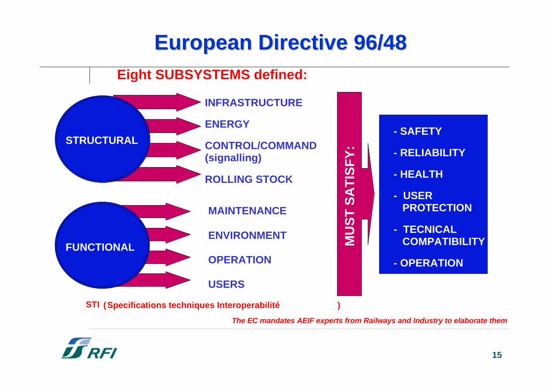
Eight SUBSYSTEMS defined:
STRUCTURAL
FUNCTIONAL
INFRASTRUCTURE
ENERGY
CONTROL/COMMAND(signalling)
ROLLING STOCK
MAINTENANCE
ENVIRONMENT
OPERATION
USERS
MU
ST
SA
TIS
FY
:
- SAFETY
- RELIABILITY
- HEALTH
- USER PROTECTION
- TECNICAL COMPATIBILITY
- OPERATION
STI (Specifications techniques Interoperabilité )
The EC mandates AEIF experts from Railways and Industry to elaborate them
European Directive 96/48European Directive 96/48
16
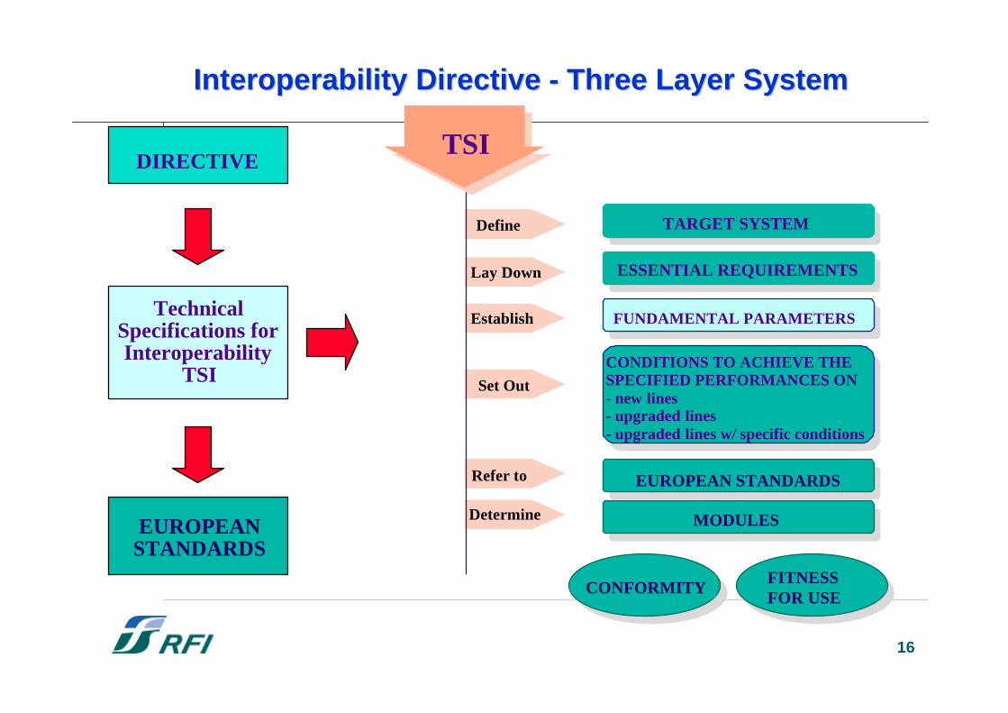
Interoperability DirectiveInteroperability Directive - - Three Layer System Three Layer System
ESSENTIAL REQUIREMENTS
FUNDAMENTAL PARAMETERS
TARGET SYSTEM
CONDITIONS TO ACHIEVE THESPECIFIED PERFORMANCES ON- new lines- upgraded lines- upgraded lines w/ specific conditions
EUROPEAN STANDARDS
MODULES
CONFORMITY FITNESSFOR USE
TSI
Define
Lay Down
Establish
Set Out
Refer to
DetermineEUROPEAN
STANDARDS
TechnicalSpecifications forInteroperability
TSI
DIRECTIVE
17
Control-CommandControl-Command and and SignallingSignalling (CCS) TSI (CCS) TSI
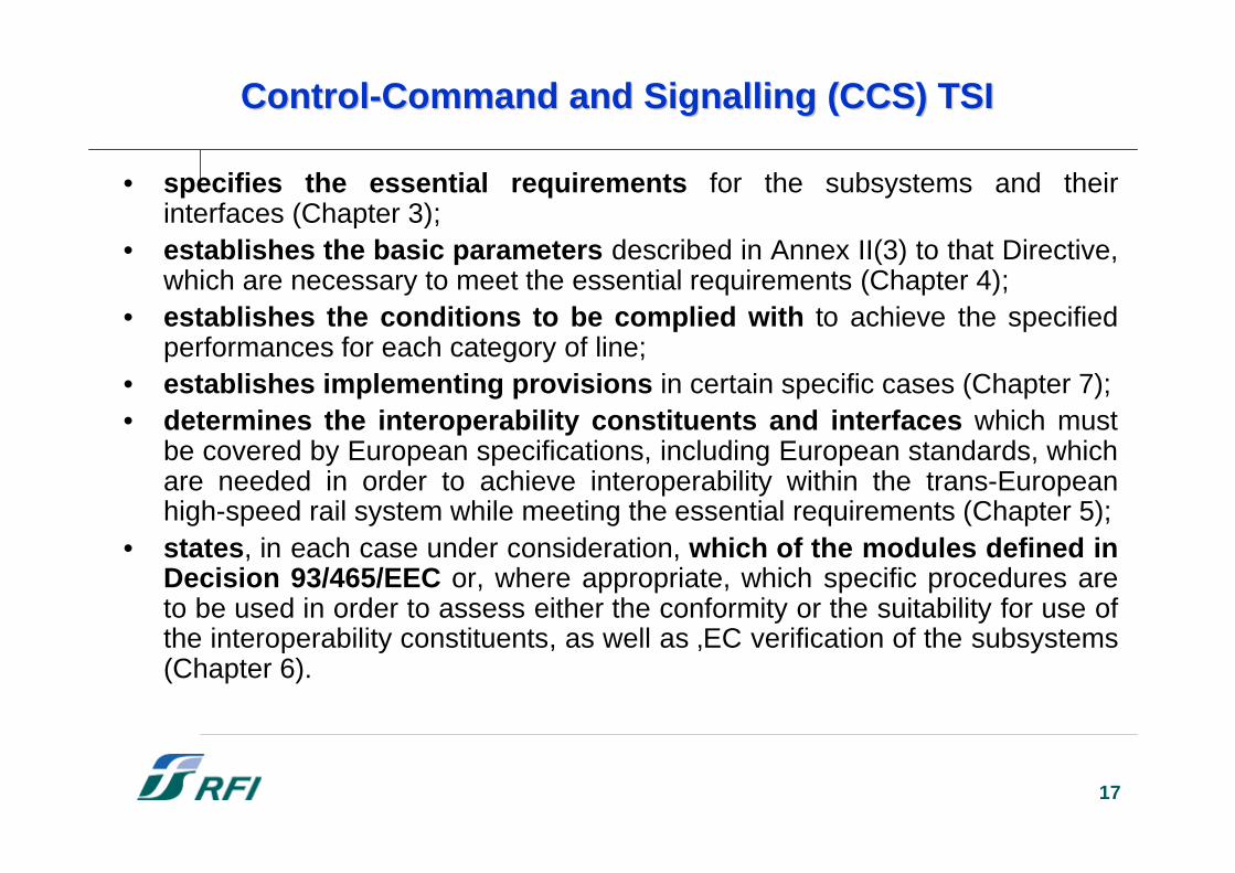
• specifies the essential requirements for the subsystems and theirinterfaces (Chapter 3);
• establishes the basic parameters described in Annex II(3) to that Directive,which are necessary to meet the essential requirements (Chapter 4);
• establishes the conditions to be complied with to achieve the specifiedperformances for each category of line;
• establishes implementing provisions in certain specific cases (Chapter 7);• determines the interoperability constituents and interfaces which must
be covered by European specifications, including European standards, whichare needed in order to achieve interoperability within the trans-Europeanhigh-speed rail system while meeting the essential requirements (Chapter 5);
• states, in each case under consideration, which of the modules defined inDecision 93/465/EEC or, where appropriate, which specific procedures areto be used in order to assess either the conformity or the suitability for use ofthe interoperability constituents, as well as ‚EC verification of the subsystems(Chapter 6).
18
CCS-SS: CCS-SS: DefinitionDefinition and Scope and Scope
• Definition: The control-command subsystem is defined asthat set of functions and their implementation which allowthe safe and predictable movement of rail traffic in orderto meet the desired operational activities.
• Scope: The TSI control-command defines the essentialrequirements for those parts of the control-commandsubsystem that have relevance to interoperability, andtherefore are subject to EC declaration of verification.
19
CCS-SS: CCS-SS: TechnicalTechnical InteroperabilityInteroperability
• Technical interoperability ensures that the trains are ableto run safely on the interoperable lines, receiving thenecessary control-command data from the trackside.
• Technical interoperability is obtained by providing thetrains with the correct functions, interfaces andperformance for the infrastructure over which the serviceis to pass.
• Technical interoperability is the prerequisite for operatio-nal interoperability, in which the driving is based on con-sistent information displayed in the cabs and is in accor-dance with signalling principles defined for the high-speednetwork that are independent of the technology used.
20
CCS-SS CCS-SS CharacterisationCharacterisation: : FunctionsFunctions
• the cab-signalling function;• the automatic train protection function, comprising: selecting the
speed supervision mode, defining and providing the interventionfunction, setting the train characteristics;
• proving train integrity;• equipment health monitoring and failure mode support, comprising:
initialising the subsystem, testing the subsystem in service, testingthe subsystem in depot, providing failure mode support;
• exchanging data between the trackside assembly and the on-boardassembly;
• managing the STMs;• support to cab-signalling and automatic train protection, comprising:
supporting driving, providing odometry, recording data, the vigilancefunction.
Note: to achieve interoperability it is not necessary to standardise all thefunctions within the whole control-command and signalling subsystem.
21
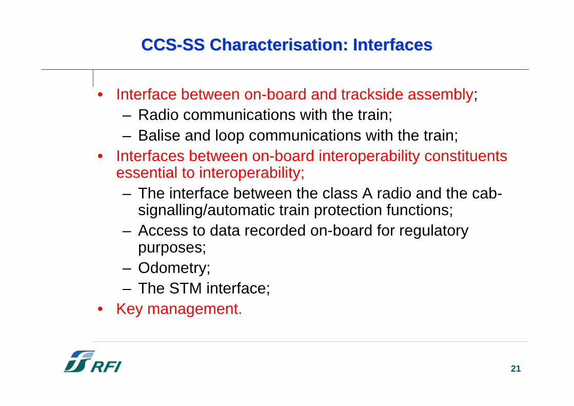
CCS-SS CCS-SS CharacterisationCharacterisation: : InterfacesInterfaces
• Interface between on-board and trackside assembly;– Radio communications with the train;– Balise and loop communications with the train;
• Interfaces between on-board interoperability constituentsessential to interoperability;– The interface between the class A radio and the cab-
signalling/automatic train protection functions;– Access to data recorded on-board for regulatory
purposes;– Odometry;– The STM interface;
• Key management.
22
InteroperabilityInteroperability ConstituentsConstituents: On-Board : On-Board AssemblyAssembly
• ERTMS/ETCS on-board;• Safety platform on-board;• Safety information recorder;• Odometry;• External STM;• ERTMS/GSM-R on-board.
23
InteroperabilityInteroperability ConstituentsConstituents: : TrackSideTrackSide AssemblyAssembly
• ERTMS/ETCS trackside;• Eurobalise;• Euroloop;• LEU (Eurobalise);• LEU (Euroloop);• Safety platform trackside.
24
199619961996
200120012001
199819981998
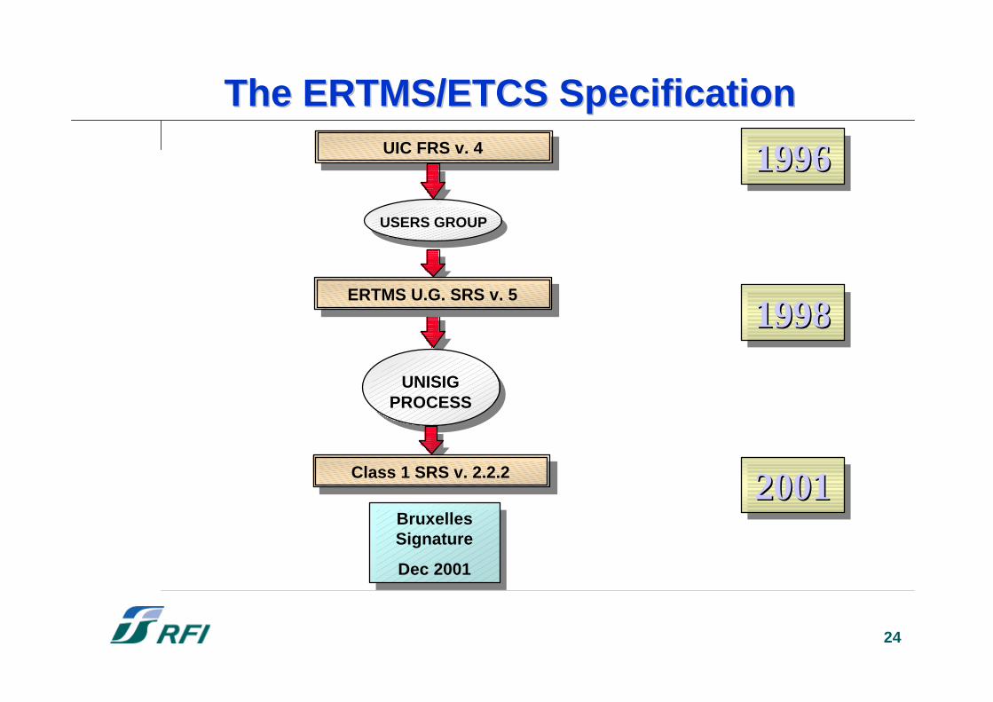
UNISIGPROCESS
Class 1 SRS v. 2.2.2Class 1 SRS v. 2.2.2
BruxellesSignature
Dec 2001
BruxellesSignature
Dec 2001
UIC FRS v. 4UIC FRS v. 4
The ERTMS/ETCS Specification The ERTMS/ETCS Specification
ERTMS U.G. SRS v. 5ERTMS U.G. SRS v. 5
USERS GROUP
25
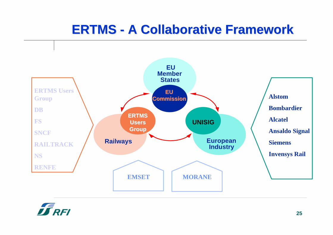
ERTMS - A Collaborative FrameworkERTMS - A Collaborative Framework
EUMemberStates
EuropeanIndustry
Railways
ERTMSERTMSUsersUsersGroupGroup
UNISIG
Alstom
Bombardier
Alcatel
Ansaldo Signal
Siemens
Invensys Rail
ERTMS UsersGroup
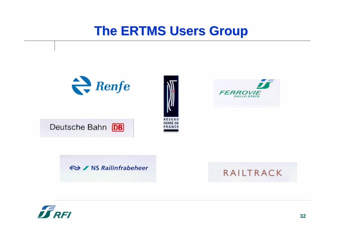
DB
FS
SNCF
RAILTRACK
NS
RENFE
MORANEEMSET
EUEUCommissionCommission
26
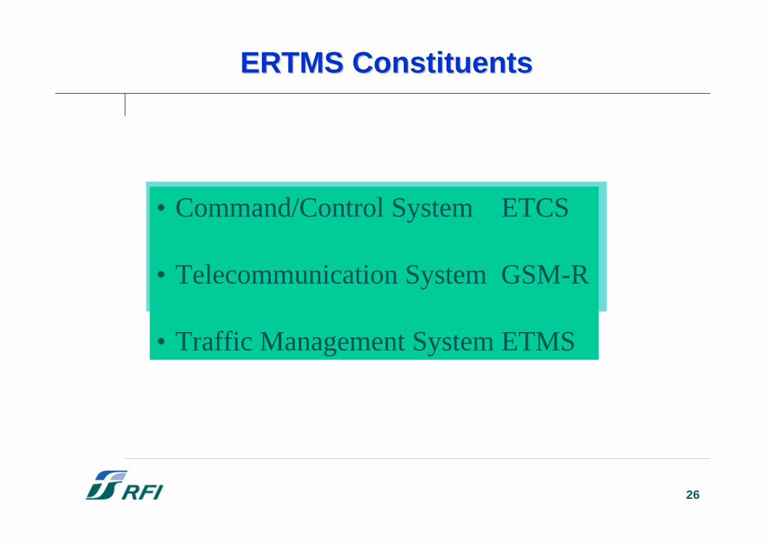
• Command/Control System ETCS
• Telecommunication System GSM-R
• Traffic Management System ETMS
ERTMS ConstituentsERTMS Constituents
27
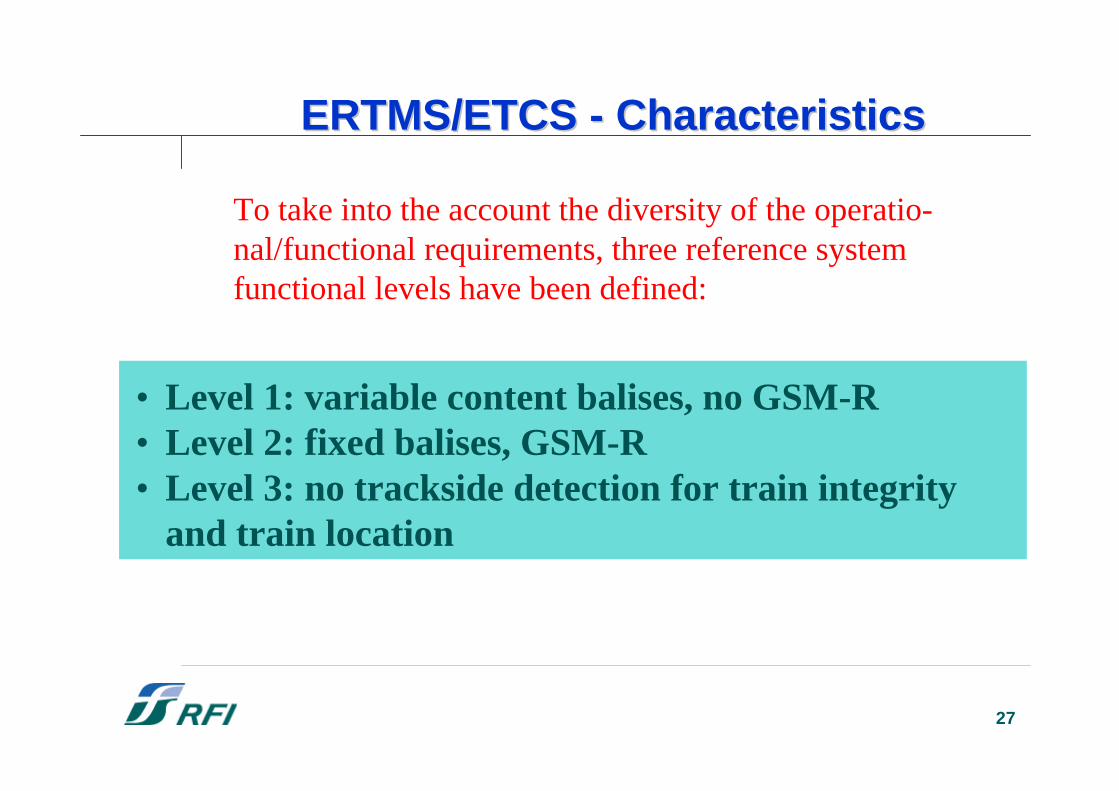
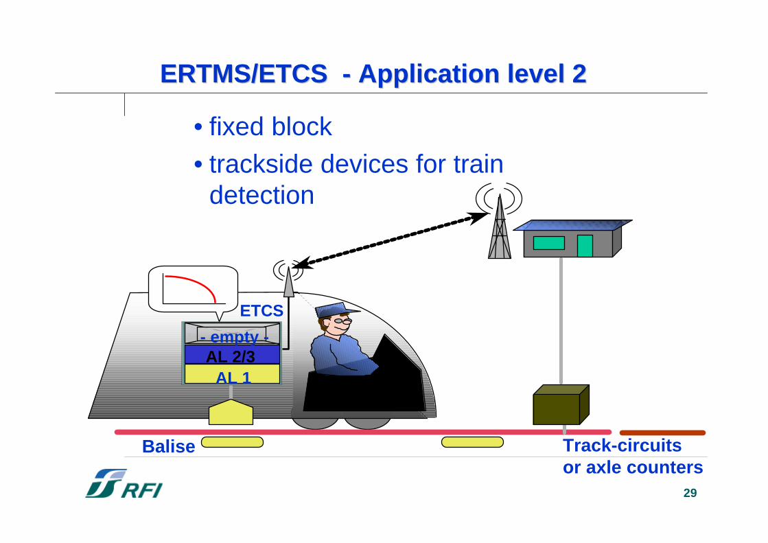
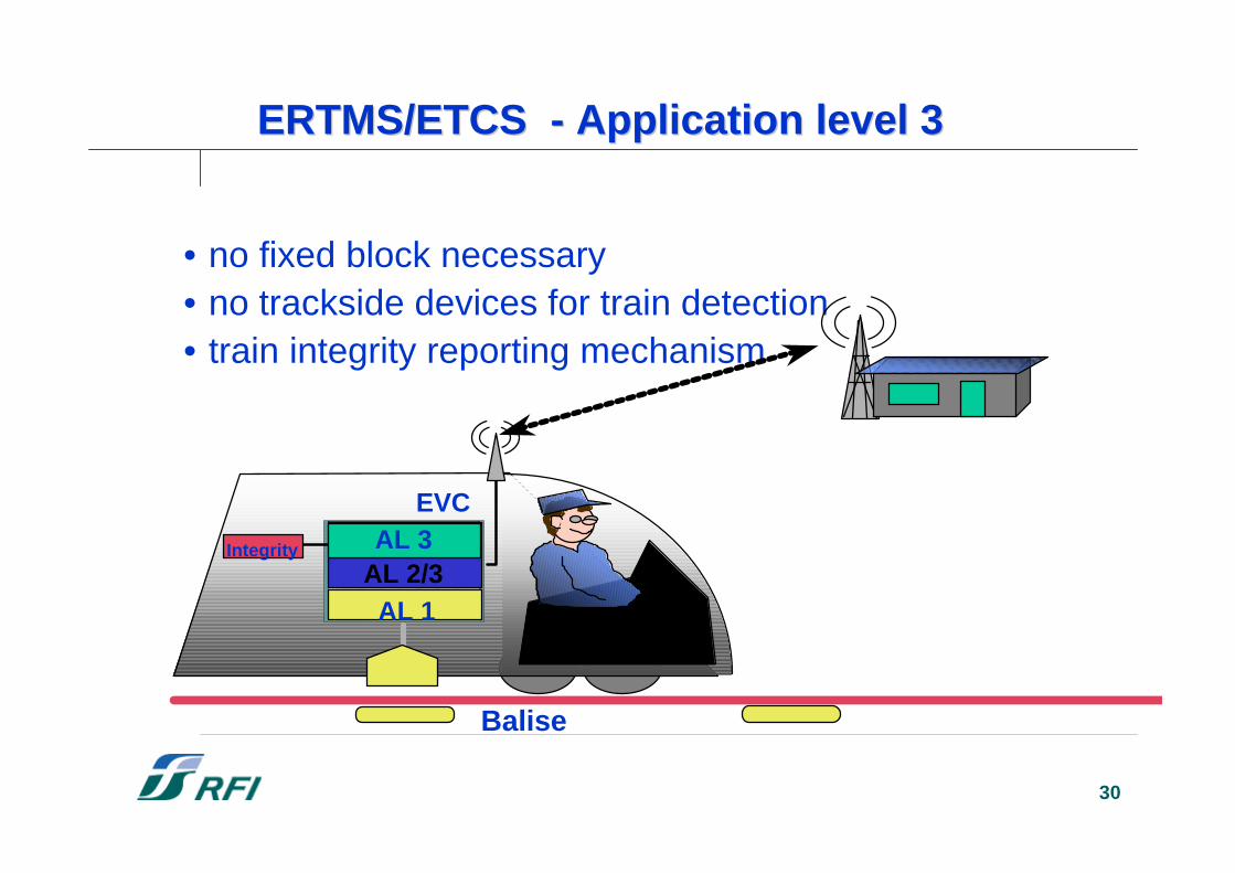
• Level 1: variable content balises, no GSM-R• Level 2: fixed balises, GSM-R• Level 3: no trackside detection for train integrity
and train location
ERTMS/ETCS -ERTMS/ETCS - CharacteristicsCharacteristics
To take into the account the diversity of the operatio-nal/functional requirements, three reference systemfunctional levels have been defined:
28
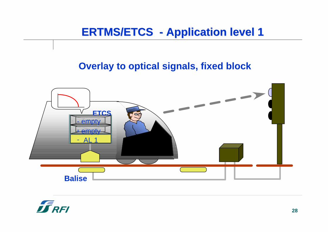
ERTMS/ETCS - Application level 1ERTMS/ETCS - Application level 1
Balise
ETCS
AL 1- empty-
- empty-
Overlay to optical signals, fixed block
29
• fixed block• trackside devices for train
detection
Balise
AL 1AL 2/3
ETCS
- empty -
ERTMS/ETCS - Application level 2ERTMS/ETCS - Application level 2
Track-circuits or axle counters
30
• no fixed block necessary• no trackside devices for train detection• train integrity reporting mechanism
Balise
AL 1AL 2/3
EVC
ERTMS/ETCS - Application level 3ERTMS/ETCS - Application level 3
Integrity AL 3
31
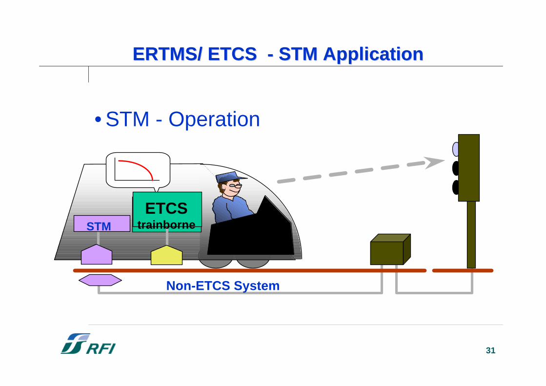
• STM - Operation
Non-ETCS System
STMETCS
trainborne
ERTMS/ ETCS - STM ApplicationERTMS/ ETCS - STM Application
32
The ERTMS Users GroupThe ERTMS Users Group
33
The ERTMS Users GroupThe ERTMS Users Group
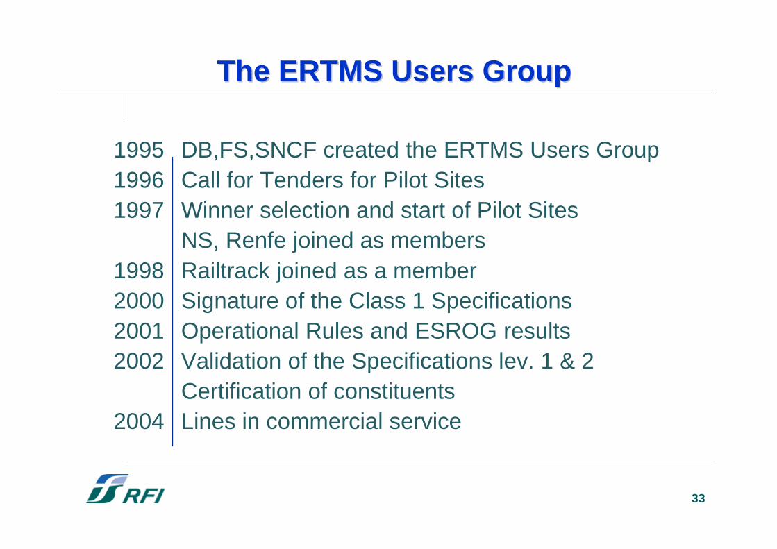
1995 DB,FS,SNCF created the ERTMS Users Group1996 Call for Tenders for Pilot Sites1997 Winner selection and start of Pilot Sites
NS, Renfe joined as members1998 Railtrack joined as a member2000 Signature of the Class 1 Specifications2001 Operational Rules and ESROG results2002 Validation of the Specifications lev. 1 & 2
Certification of constituents2004 Lines in commercial service
34
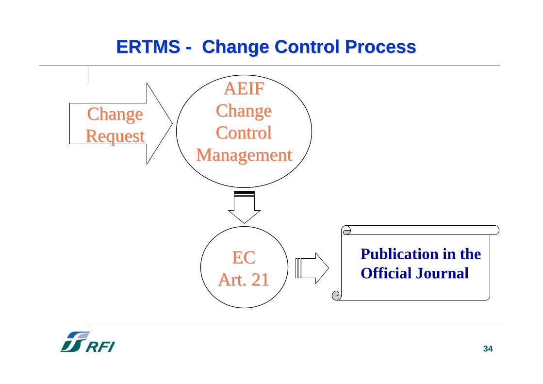
ChangeChangeRequestRequest
ERTMS - Change Control ProcessERTMS - Change Control Process
AEIFAEIFChangeChangeControlControl
ManagementManagement
ECECArt. 21Art. 21
Publication in theOfficial Journal
35
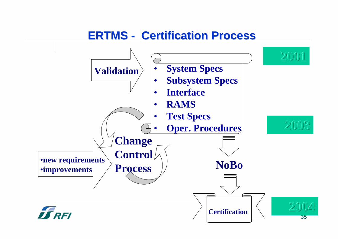
•new requirements•improvements
ChangeControlProcess
• System Specs• Subsystem Specs• Interface• RAMS• Test Specs• Oper. Procedures
Validation
Certification
NoBo
200120012001
200320032003
200420042004
ERTMS - Certification ProcessERTMS - Certification Process
36
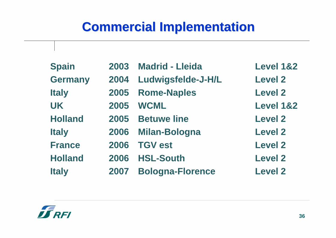
Commercial ImplementationCommercial Implementation
Spain 2003 Madrid - Lleida Level 1&2Germany 2004 Ludwigsfelde-J-H/L Level 2Italy 2005 Rome-Naples Level 2UK 2005 WCML Level 1&2Holland 2005 Betuwe line Level 2Italy 2006 Milan-Bologna Level 2France 2006 TGV est Level 2Holland 2006 HSL-South Level 2Italy 2007 Bologna-Florence Level 2
37
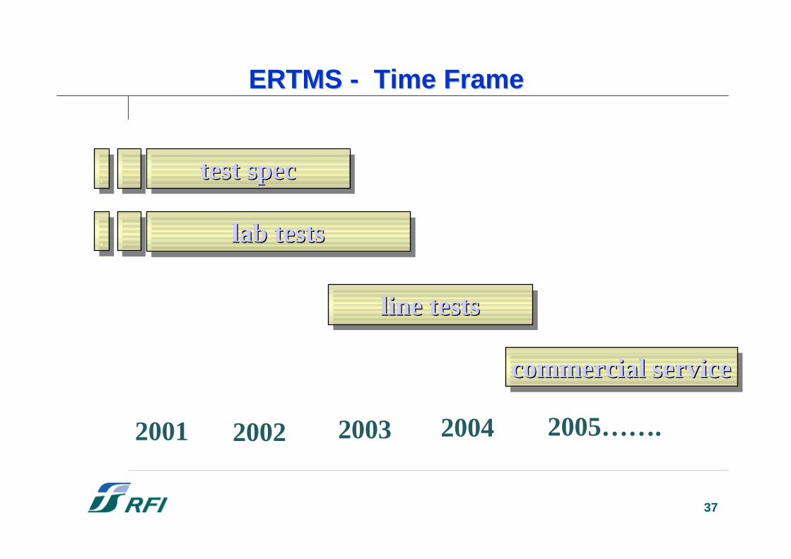
ERTMS - Time FrameERTMS - Time Frame
test spectest test specspec
lab testslab testslab tests
line testsline testsline tests
2001 2002 2003 2004
..
..
commercial servicecommercialcommercial serviceservice
2005…….
38
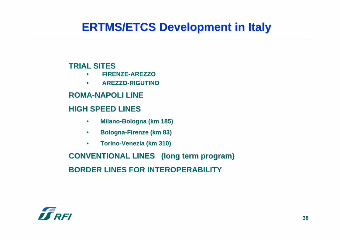
TRIAL SITESTRIAL SITES•• FIRENZE-AREZZOFIRENZE-AREZZO•• AREZZO-RIGUTINO AREZZO-RIGUTINO
RROMA-NAPOLI LINEOMA-NAPOLI LINE
HIGH SPEED LINESHIGH SPEED LINES
•• MilanoMilano-Bologna (km 185-Bologna (km 185))
•• BBologna-Firenzeologna-Firenze (km 83 (km 83))
•• Torino-VeneziaTorino-Venezia (km 310 (km 310))
CONVENTIONAL LINES (long term program)CONVENTIONAL LINES (long term program)
BORDER LINES FOR INTEROPERABILITY
ERTMS/ERTMS/ETCSETCS DevelopmentDevelopment in in ItalyItaly
39
•• Test on trial sites 2002 – 2004Test on trial sites 2002 – 2004
•• Assessment of components (RBC,Assessment of components (RBC,EurocabEurocab, ...) and test on the Roma-, ...) and test on the Roma-NapoliNapoliline in 2004line in 2004
•• ETCS in service within 2005ETCS in service within 2005
ERTMS/ETCSERTMS/ETCS DevelopmentDevelopment in in ItalyItaly
40
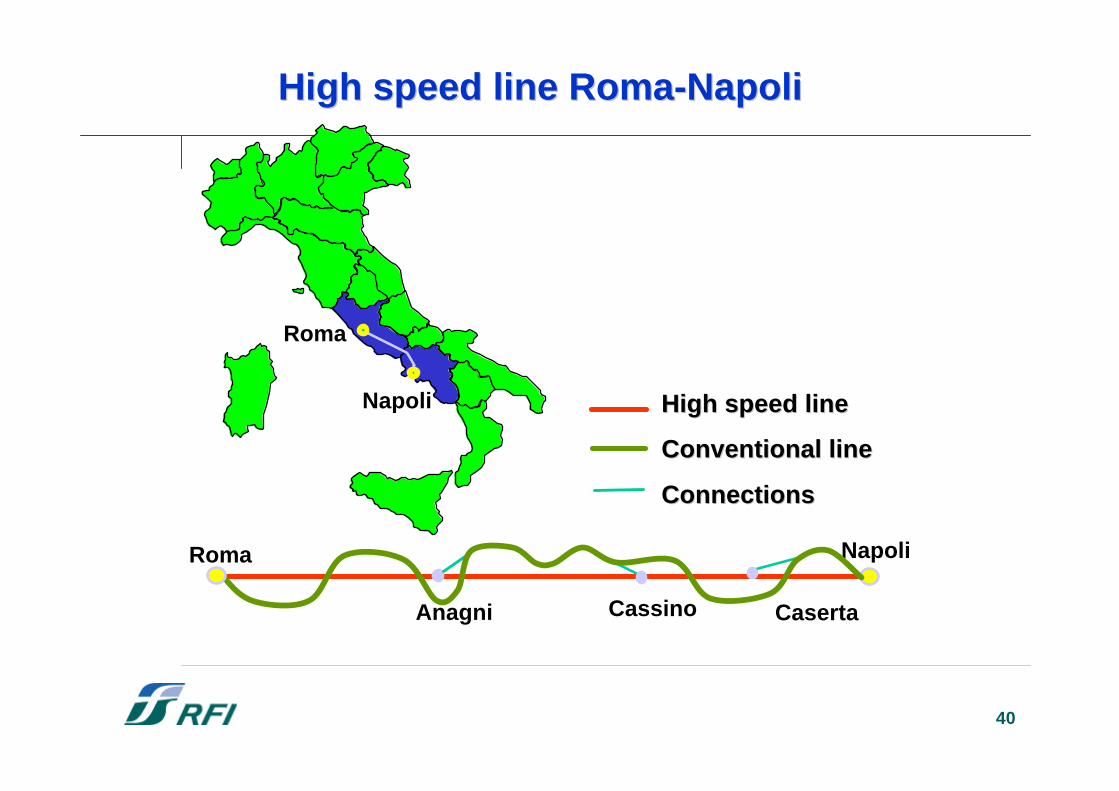
High speed line Roma-High speed line Roma-NapoliNapoli
Roma
Napoli High speed lineHigh speed line
Conventional lineConventional line
ConnectionsConnections
Napoli
Anagni
Roma
Cassino Caserta
41
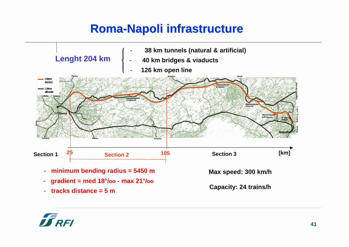
Lenght 204 km
Roma-Roma-NapoliNapoli infrastructure infrastructure
- 38 km tunnels (natural & artificial)
- 126 km open line
Section 1 Section 2 Section 3 [km]10525
- minimum bending radius = 5450 m
- gradient = med 18°/oo - max 21°/oo
- tracks distance = 5 m
Max speed: 300 km/h
Capacity: 24 trains/h
- 40 km bridges & viaducts
42
§§ Power supplyPower supply 2x25 kV a.c.2x25 kV a.c.
§§ Telecommunications:Telecommunications:•• Transmission system Transmission system SDH-STM4-622Mbit/sSDH-STM4-622Mbit/s•• Track/train radio system Track/train radio system GSM-RGSM-R
§§ Control & CommandControl & Command ERTMS level 2ERTMS level 2
Roma-Roma-NapoliNapoli Technologies Technologies
43
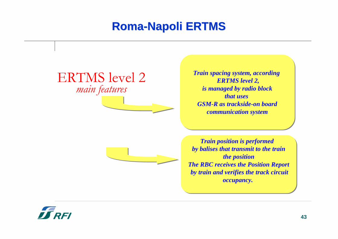
Roma-Roma-NapoliNapoli ERTMS ERTMS
ERTMS level 2main features
Train spacing system, according ERTMS level 2,
is managed by radio blockthat uses
GSM-R as trackside-on board communication system
Train spacing system, according ERTMS level 2,
is managed by radio blockthat uses
GSM-R as trackside-on board communication system
Train position is performed by balises that transmit to the train
the positionThe RBC receives the Position Report by train and verifies the track circuit
occupancy.
Train position is performed by balises that transmit to the train
the positionThe RBC receives the Position Report by train and verifies the track circuit
occupancy.
44
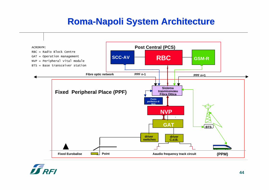
Roma-Roma-NapoliNapoli System Architecture System Architecture
Sistema trasmissivo su
Fibra Ottica
PPF n+1PPF n-1
Fixed Peripheral Place (PPF)
Post Central (PCS)
Fibre optic network
driverswitches
driverC.d.B.
GAT
Fixed Eurobalise
BTS
RBC
Aaudio frequency track circuitPoint
GSM-RSCC-AV
Postoperiferico di
SCC
(PPM)
NVP
ACRONYM:RBC = Radio Block CentreGAT = Operation managementNVP = Peripheral vital moduleBTS = Base transceiver station
45
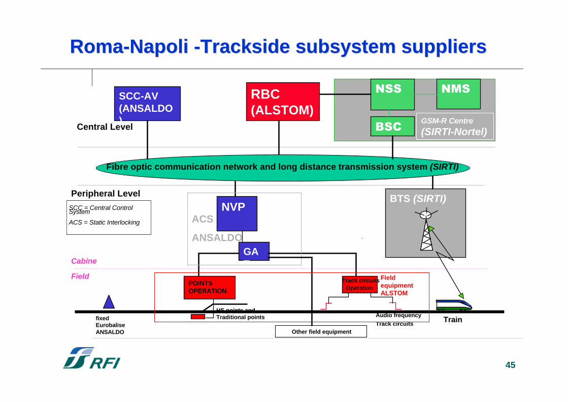
Audio frequencyTrack circuits
BTS (SIRTI)
RBC(ALSTOM)
GAT
Central Level
POINTSOPERATION
Track circuitsOperation
fixedEurobaliseANSALDO
HS points andTraditional points
NSSSCC-AV(ANSALDO)
Train
NVP
Fibre optic communication network and long distance transmission system (SIRTI)
NMS
BSC GSM-R Centre(SIRTI-Nortel)
Peripheral Level
SCC = Central ControlSystem
ACS = Static Interlocking
Other field equipment
Cabine
Field FieldequipmentALSTOM
ACS
ANSALDO
Roma-Roma-NapoliNapoli -Trackside subsystem suppliers -Trackside subsystem suppliers
46
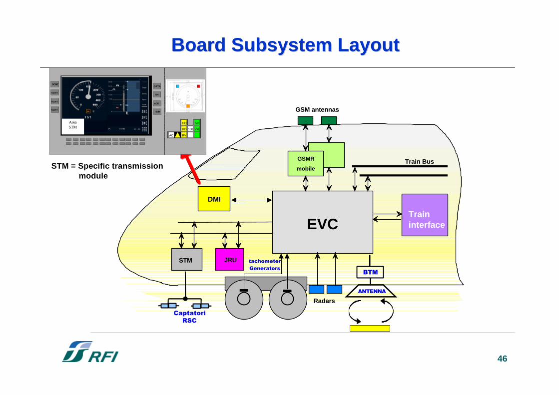
STM JRU
Traininterface
GSMR
mobile
GSM antennas
Train Bus
Radars
EVC
BTM
ANTENNA
Generatorstachometer
CaptatoriRSC
DMI
STM = Specific transmission module
DATA
SH
ACK
SoM
DATA
SH
ACK
SoM
AREA SCMT
SCMT
SCMT
SCMT
SCMT
130
100
RV
VM
SV
150
AC
130
100
RV
VM
SV
150
AC
130
100
RV
VM
SV
150
AC
130
100
RV
VM
SV
150
AC
130
100
RV
VM
SV
150
AC
130
100
RV
VM
SV
150
AC
130
100
RV
VM
SV
150
AC
130
100
RV
VM
SV
150
AC
130
100
RV
VM
SV
150
AC
130
100
RV
VM
SV
150
AC
130
100
RV
VM
SV
150
AC
130
100
RV
VM
SV
150
AC
130
100
RV
VM
SV
150
AC
AreaSTM
Board Subsystem LayoutBoard Subsystem Layout
47
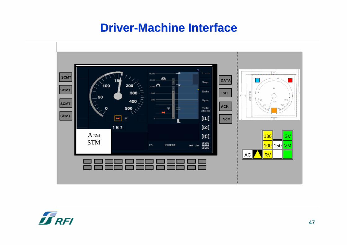
Driver-MachineDriver-Machine Interface Interface
DATA
SH
ACK
SoM
DATA
SH
ACK
SoM
AREA SCMT
SCMT
SCMT
SCMT
SCMT
130
100
RV
VM
SV
150
AC
130
100
RV
VM
SV
150
AC
130
100
RV
VM
SV
150
AC
130
100
RV
VM
SV
150
AC
130
100
RV
VM
SV
150
AC
130
100
RV
VM
SV
150
AC
130
100
RV
VM
SV
150
AC
130
100
RV
VM
SV
150
AC
130
100
RV
VM
SV
150
AC
130
100
RV
VM
SV
150
AC
130
100
RV
VM
SV
150
AC
130
100
RV
VM
SV
150
AC
130
100
RV
VM
SV
150
AC
AreaSTM
48
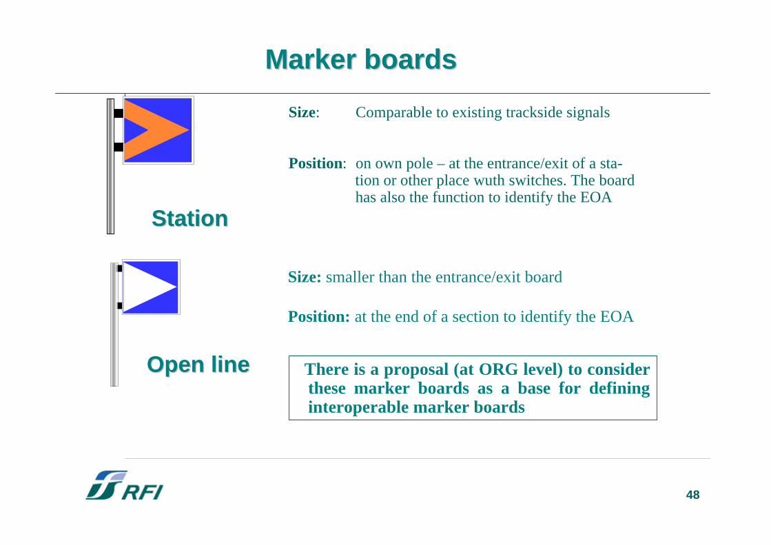
Marker Marker boardsboards
Size: Comparable to existing trackside signals
Position: on own pole – at the entrance/exit of a sta- tion or other place wuth switches. The board has also the function to identify the EOA
StationStation
Size: smaller than the entrance/exit board
Position: at the end of a section to identify the EOA
Open lineOpen line There is a proposal (at ORG level) to considerthese marker boards as a base for defininginteroperable marker boards
49
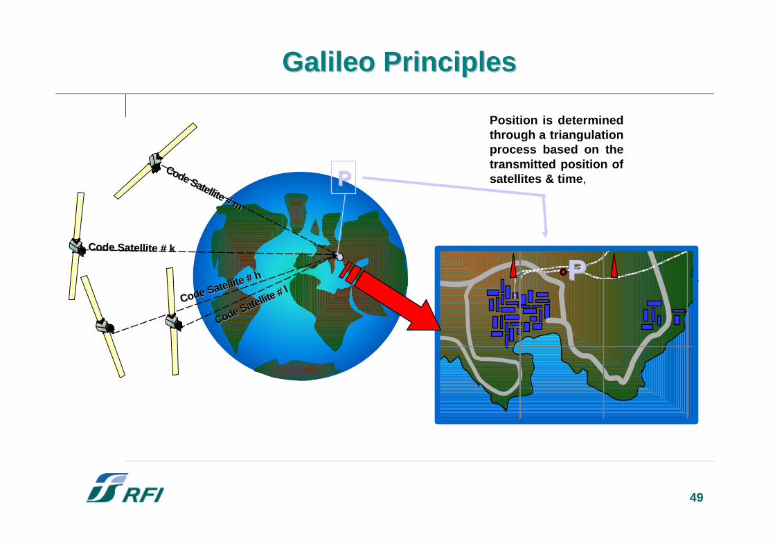
Galileo Galileo PrinciplesPrinciples
Code Satellite # m
Code Satellite # m
PP
PP
Position is determinedthrough a triangulationprocess based on thetransmitted position ofsatellites & time,
Code Satellite # kCode Satellite # k
Code Satellite # h
Code Satellite # h
Code Satellite # l
Code Satellite # l
50
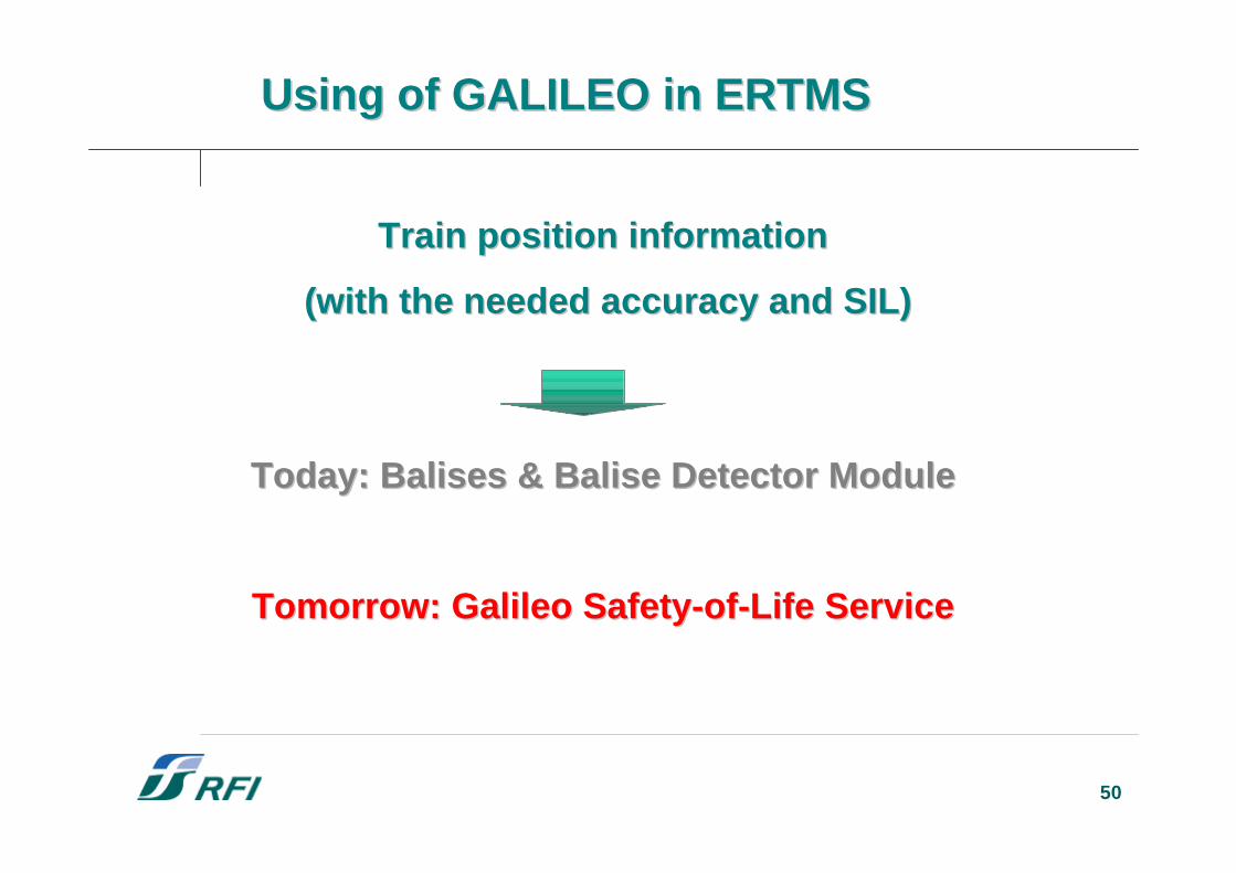
TrainTrain position position informationinformation
( (withwith the the neededneeded accuracyaccuracy and SIL) and SIL)
Today: Balises & Balise Detector ModuleToday: Balises & Balise Detector Module
TomorrowTomorrow: Galileo : Galileo Safety-of-LifeSafety-of-Life ServiceService
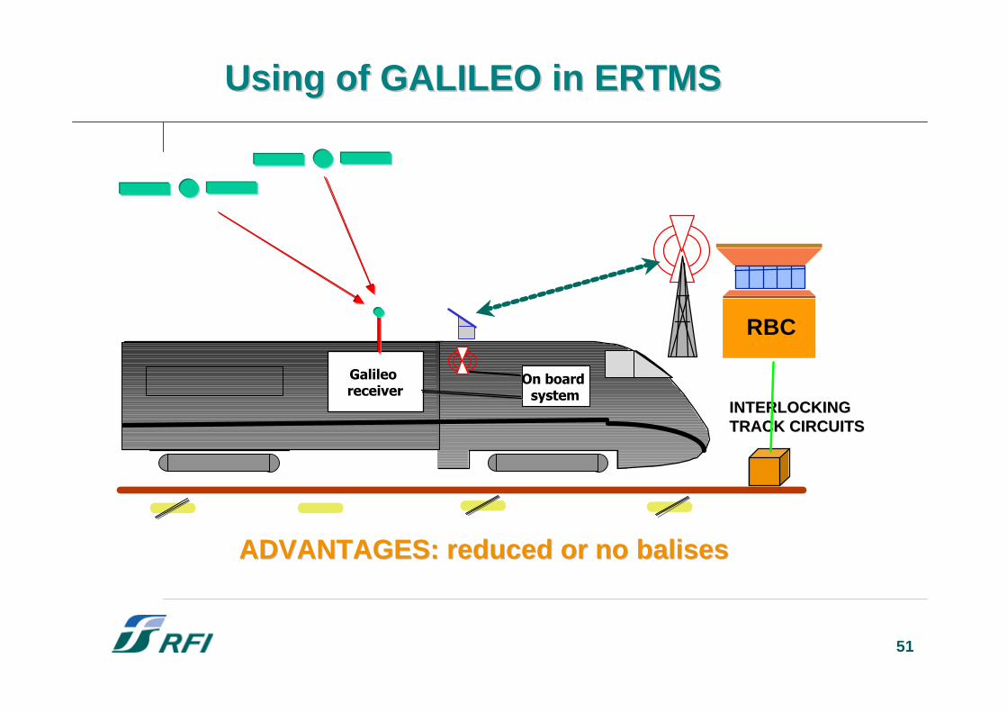
UsingUsing of GALILEO in ERTMS of GALILEO in ERTMS
51
On board system
Galileo receiver
INTERLOCKINGINTERLOCKINGTRACK CIRCUITSTRACK CIRCUITS
RBC
ADVANTAGES: ADVANTAGES: reducedreduced or no or no balisesbalises
UsingUsing of GALILEO in ERTMS of GALILEO in ERTMS