ericsson mobile phone type 1030601-bv ef-738.pdf · the ericsson service philosophy includes the...
TRANSCRIPT

service manual
Ericsson Mobile PhoneType 1030601-BV
EN/LZB 126 1319 R2A

System Introduction
Service Messages
Spare Parts
1
2
4
3
6
7
8
EricssonMobilePhone
Accessories
HandsFree Installation
5
ServiceTechnical Description
Test/Service Programs
Manual
Service Instructions
EN/LZB 126 1319 R2A
1030601-BV

Second Edition (January 1998)Publication number: EN/LZB 126 1319 R2A
All Rights ReservedPrinted in Sweden 1998
© Ericsson Mobile Communications AB, 1998

Preface
The Ericsson service philosophy includes the ambition that engineers serving our telephones also possess a general knowledge of the system for which they are intended, as well as of the phone itself and its accessories.This manual contains consequently not only information regarding the actual serv-ice work but also additional information as stated below.
Section 1: System Introduction- network description- frequency tables
Section 2: Technical Description- description of the mechanical design- operational description of the electronic circuitries- technical specifications
Section 3: Test/Service Programs- test equipment- test program- ETACS service program- keypad NAM programming- flash programming
Section 4: Service Instructions- system connector signals- disassembly/reassembly- PCB exchange- fault finding and alignment
Section 5: Accessories- technical descriptions of available accessories
Section 6: HandsFree Installation- installation instructions regarding vehicle handsfree kits
Section 7: Spare Parts- section reserved for separately distributed spare parts lists
Section 8: Service Messages- section reserved for separately distributed service messages


Contents
1 System IntroductionThe Mobile Telephone Network_______________________________ 5Frequency Tables__________________________________________ 11
2 Technical DescriptionOverview_________________________________________________ 7Mechanical Design________________________________________ 11Man Machine Interface (MMI)_______________________________ 12Radio Design_____________________________________________ 13Power and Charging Design_________________________________ 20User Interface____________________________________________ 23Logic Design_____________________________________________ 24Audio Design_____________________________________________ 27Software Design__________________________________________ 33Technical Specifications____________________________________ 34
3 Test/Service ProgramsTest Equipment____________________________________________ 5Test Program______________________________________________ 7ETACS Service Programs___________________________________ 17Keypad NAM Programming_________________________________ 33Flash Programming________________________________________ 43
4 Service InstructionsSystem Connector Signals____________________________________ 5Disassembly_______________________________________________ 6Reassembly_______________________________________________ 7Exchanging the Circuit Board_________________________________ 9Fault Finding and Alignment________________________________ 10
5 AccessoriesRapid Charger_____________________________________________ 7Travel Charger_____________________________________________ 9Vehicle Power/Charger_____________________________________ 13DeskTop Charger MC7000__________________________________ 17Portable HandsFree________________________________________ 25Vehicle HandsFree Solution HF7300__________________________ 27Vehicle HandsFree Solution HF7600__________________________ 35
6 HandsFree InstallationVehicle HandsFree Solutions HF7300 & HF7600_________________ 5
7 Spare Parts
8 Service Messages


System IntroductionEricsson Mobile Phone EF738

System Introduction
2
System Introduction
3
Contents
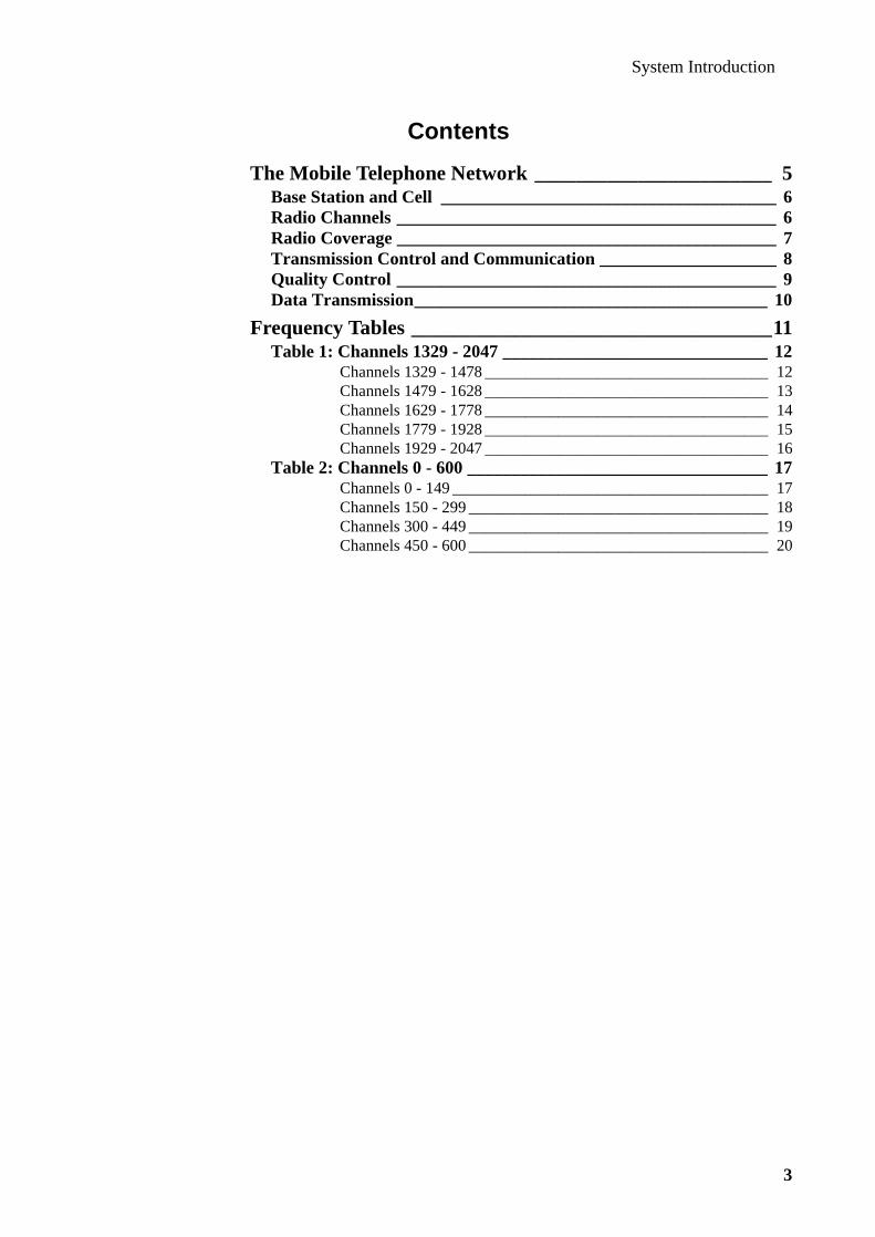
The Mobile Telephone Network _______________________ 5Base Station and Cell ______________________________________ 6Radio Channels ___________________________________________ 6Radio Coverage ___________________________________________ 7Transmission Control and Communication ____________________ 8Quality Control ___________________________________________ 9Data Transmission________________________________________ 10
Frequency Tables ___________________________________11Table 1: Channels 1329 - 2047 ______________________________ 12
Channels 1329 - 1478 ___________________________________ 12Channels 1479 - 1628 ___________________________________ 13Channels 1629 - 1778 ___________________________________ 14Channels 1779 - 1928 ___________________________________ 15Channels 1929 - 2047 ___________________________________ 16
Table 2: Channels 0 - 600 __________________________________ 17Channels 0 - 149 _______________________________________ 17Channels 150 - 299 _____________________________________ 18Channels 300 - 449 _____________________________________ 19Channels 450 - 600 _____________________________________ 20

System Introduction
4

System Introduction
5
The Mobile Telephone Network
A cellular mobile telephone system (CMS) controlled by one single exchange is illustrated in fig. 1. The basic units of such a system are:
• the mobile services switching centre (MSC)
• the base stations (BS)
• the mobile telephones (MT)
The MSC is the interface between the radio system and the public switching tele-phone network (PSTN). Calls to and from the mobile subscriber are switched by the MSC, which also provides all signalling functions needed to establish the calls.
In order to obtain radio coverage of a given geographical area, a certain number of base stations is required. The number of base stations may range from one up to a hundred or more. Such a geographical area is called an MSC service area.
The number of MSCs varies from one country to another, depending on traffic den-sity, the number of base stations, and so on. Each MSC handles calls from one serv-ice area which, in turn, is divided into radio zones. A service area consists of a number of radio zones (or cells), each of which is serviced by a base station.
Figure 1: Basic Units in the Mobile Telephone System

System Introduction
6
Base Station and Cell
A base station is able to communicate with any mobile telephone within a certain area close to it. This area is called a cell.
The base station contains channel units. Each channel unit is equipped with a radio transmitter, a radio receiver, and a control unit. The control unit is used for data communication with the MSC and for data signalling with the mobile telephones on the radio path. A channel uses two separate radio frequencies, one for transmission by the mobile telephone and one for transmission by the base station. Such a chan-nel is called a duplex channel. The distance between these two frequencies, the duplex distance, is always the same and is 45 MHz.
All base stations within a service area are connected to the MSC via dedicated lines in the public telephone network.
Radio Channels
Two different types of radio channels exist in a base station:
• voice channels (VC)
• control channels (CC)
The majority of channel units are voice channel units. Such a voice channel unit is engaged in carrying one telephone call at a time. Depending on how many simulta-neous calls a base station is required to handle, the number ofvoice-channel units in some base stations may be only a few, while in others up to a hundred or more.
There is normally only one control channel in each cell. A mobile telephone being within a cell, and not in the conversation state, is always tuned to the control chan-nel of this cell. The telephone supervises the continuous data stream.
The total number of channels available in a mobile telephone system is limited. As the radio waves only reach so far from the base station, however, identical channel frequencies can be used by several base stations, provided the distance between them is sufficient to prevent interference. This method is used to increase the capac-ity of the system.
Figure 2: Channel Unit

System Introduction
7
Radio Coverage
The coverage (or the transmitting power) of the base station is adjusted to the amount of traffic, so less power is used in cities and other areas where the traffic is heavy. The covered area in these cases may be limited to about two kilometers. More power is permissible in less populated areas. The range in these areas may amount to about 40 kilometres.
A method known as the small-cell technique may be applied in areas with an extreme demand on radio capacity. With this technique the service area to be cov-ered is divided into a number of radio zones (see fig. 3). Each radio zone is covered by a base station, which includes a transmitter (Tx) and a receiver (Rx). For such a system to operate, without the base stations interfering with each other, the available frequency band is split up, for example into six different groups (A-F), with a cer-tain number of frequencies in each group. Allocating these groups in such a way that no radio zone operating on a particular group of frequencies adjoins another operating on the same frequencies makes it possible to cover an entire service area, without any interference between the base stations. Fig. 4 shows an example of channel allocation.
Figure 3: Service Areas with Radio Zones and Base Stations
Figure 4: Channel Allocation
A
E
E
C
C
D
D
B
B
F
F BE
AD
CF A9
105
6
7 8
3
4
2 1

System Introduction
8
In order to reduce the risk of interference still further, and to remove noise, the sys-tem uses the compander technique. Basically, this method improves the signal/noise ratio of the radio channel by compressing the signal before transmission, and expanding the signal on reception.
The ETACS system features full duplex operation, with a duplex separation of 45 MHz. Full duplex means that a conversation can progress simultaneously in both directions, as it does on an ordinary telephone. The duplex separation is the fre-quency separation between the transmitter and receiver operating frequencies. The 900 MHz-band has been divided into an upper and a lower frequency band. The lower band (872.0125 - 904.9875 MHz) contains the mobile telephone transmitter channels, and the upper band (917.0125 - 949.9875 MHz) contains the correspond-ing mobile telephone receiver channels.
Transmission Control and Communication
The heavy traffic and the many functions applied in the system requires the tele-phone exchanges to be program-controlled. The exchange has to observe which base station is now serving the mobile telephone. When the car moves away from the original base station and comes closer to another, the exchange must request a switch-over to the more favourable station. This must occur without interrupting or cancelling the call. Switching a call in progress from one base station to another is called Handoff or Handover. Before transferring the communication line to a new base station, the exchange makes sure that this is really the station that will provide the best conditions for transmission and reception.
To enable the exchange to supervise transmission as indicated above, there is a con-tinuous flow of data between the mobile telephones and the exchange via the base stations. This information, which cannot be heard in the telephone, concerns chan-nel selection, transmission power, identification of sender and receiver, start and ter-mination of call, and so on. The information enables the exchange that holds the subscriber registered to follow the movements of the mobile telephone. Should the subscriber's unit come into the control area of a different exchange, this exchange will immediately report the new location to the home exchange.
When a mobile telephone approaches the limit of the system's coverage, or when neighbouring base stations cannot offer a free channel, conversation shall continue on the active channel until reception quality gets below a specified level.
The channels of the system are automatically scanned and analyzed with regard to channel number, voice channel, control channel and service area. Normally, the mobile telephone is locked on a control channel in the service area where it is located. If the telephone becomes unlocked, it will immediately start scanning for another control channel .
Each base station sends a search signal over the control channel. When a call is made to a mobile telephone, the setup information will be transmitted over this con-trol channel. Once the mobile telephone has responded to the call, the base station searches for a free voice channel and orders the mobile to switch to the chosen voice channel, after which the mobile subscriber will hear a ringing signal on the mobile telephone. The entire conversation between the two subscribers takes place over the voice channel selected by the base station. If a zone boundary is passed during the call, the channel will be switched over automatically to the new base station and the call will continue without any disturbance.

System Introduction
9
If the mobile telephone makes a call, a call request will be sent to the area base sta-tion, which will select a voice channel and direct the mobile to the selected channel. As in the previous case, the call will be transmitted over the selected voice channel, until a zone boundary is passed.
The mobile telephone uses the control channel for different purposes, namely to report to the system when it passes from one service area into another. One of the purposes is for page response, which is an answer to a cell access from a mobile sta-tion , that is a call from the mobile phone or an order confirmation. When messages are sent to all mobile phones being tuned to a control channel, this is called over-head message. The system parameters are transmitted during this message and con-tain for instance the following information about the cellular system:
• AID (Area Identity) indicates system A or B, system identity number, MSC serv-ice area and location area.
• DCC (Digital Colour Code) identifies which group of cells the message belongs to.
Quality Control
Each time a connection is established, the exchange automatically measures the field intensity of the mobile telephone. During conversation, the signal-to-noise ratio is continuously measured by a monitoring signal, SAT (Supervisory Audio Tone), sent out by the base station and returned by the mobile telephone. If the base station finds that the signal strength is below a certain value, it alerts the exchange. The exchange now requests neighbouring base stations to transmit their monitoring signals and measure the signal strength. The exchange then decides which base sta-tion provides the best conditions, and orders the mobile telephone to switch to a channel of this base station instead. The mobile sends a signalling tone (ST) as response or synchronization to the base station, for instance during call setup and during handoff.

System Introduction
10
Data Transmission
Many types of signalling are used between the different parts of the ETACS system. The signalling has the following main objectives:
• MSC - MT - setting up and clearing of calls - switching of call in progress - updating - ordering of power reduction
• MSC - BS - remote control of base station - transmission of alarm
• MSC - MSC - updating of subscriber register and roaming register - transfer of call to roaming subscriber
• MSC - PSTN - setting up of calls
• BS - MT - supervision of transmission quality
The messages and orders between the different units are sent in the form of so-called words. All words have the same length. Each word is divided into a number of fields, each of which contains a given type of information. The mobile telephone has a systems section where the frames are coded and decoded. The transmission is performed by means of FSK (Frequency Shift Key) modulation, where a logic 1 is represented by a constant frequency above the carrier frequency of the transmitter. A logic 0 is represented by a constant frequency below the carrier frequency. The speed of transmission is 8 kbits/s.
System Introduction
11
Frequency Tables
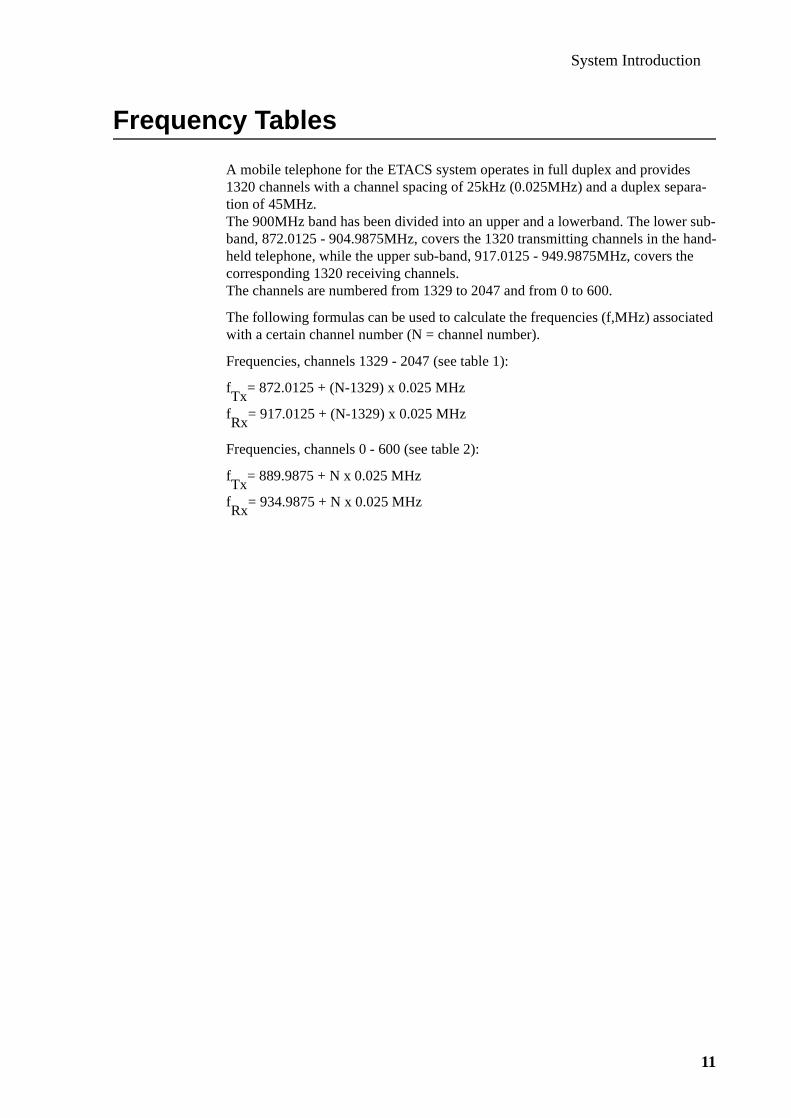
A mobile telephone for the ETACS system operates in full duplex and provides 1320 channels with a channel spacing of 25kHz (0.025MHz) and a duplex separa-tion of 45MHz.The 900MHz band has been divided into an upper and a lowerband. The lower sub-band, 872.0125 - 904.9875MHz, covers the 1320 transmitting channels in the hand-held telephone, while the upper sub-band, 917.0125 - 949.9875MHz, covers the corresponding 1320 receiving channels.The channels are numbered from 1329 to 2047 and from 0 to 600.
The following formulas can be used to calculate the frequencies (f,MHz) associated with a certain channel number (N = channel number).
Frequencies, channels 1329 - 2047 (see table 1):
fTx
= 872.0125 + (N-1329) x 0.025 MHz
fRx
= 917.0125 + (N-1329) x 0.025 MHz
Frequencies, channels 0 - 600 (see table 2):
fTx
= 889.9875 + N x 0.025 MHz
fRx
= 934.9875 + N x 0.025 MHz

System Introduction
12
Table 1: Channels 1329 - 2047
Channels 1329 - 1478
Ch. Tx Rx Ch. Tx Rx Ch. Tx Rx
1329 872.0125 917.0125 1379 873.2625 918.2625 1429 874.5125 919.51251330 872.0375 917.0375 1380 873.2875 918.2875 1430 874.5375 919.53751331 872.0625 917.0625 1381 873.3125 918.3125 1431 874.5625 919.56251332 872.0875 917.0875 1382 873.3375 918.3375 1432 874.5875 919.58751333 872.1125 917.1125 1383 873.3625 918.3625 1433 874.6125 919.61251334 872.1375 917.1375 1384 873.3875 918.3875 1434 874.6375 919.63751335 872.1625 917.1625 1385 873.4125 918.4125 1435 874.6625 919.66251336 872.1875 917.1875 1386 873.4375 918.4375 1436 874.6875 919.68751337 872.2125 917.2125 1387 873.4625 918.4625 1437 874.7125 919.71251338 872.2375 917.2375 1388 873.4875 918.4875 1438 874.7375 919.7375
1339 872.2625 917.2625 1389 873.5125 918.5125 1439 874.7625 919.76251340 872.2875 917.2875 1390 873.5375 918.5375 1440 874.7875 919.78751341 872.3125 917.3125 1391 873.5625 918.5625 1441 874.8125 919.81251342 872.3375 917.3375 1392 873.5875 918.5875 1442 874.8375 919.83751343 872.3625 917.3625 1393 873.6125 918.6125 1443 874.8625 919.86251344 872.3875 917.3875 1394 873.6375 918.6375 1444 874.8875 919.88751345 872.4125 917.4125 1395 873.6625 918.6625 1445 874.9125 919.91251346 872.4375 917.4375 1396 873.6875 918.6875 1446 874.9375 919.93751347 872.4625 917.4625 1397 873.7125 918.7125 1447 874.9625 919.96251348 872.4875 917.4875 1398 873.7375 918.7375 1448 874.9875 919.9875
1349 872.5125 917.5125 1399 873.7625 918.7625 1449 875.0125 920.01251350 872.5375 917.5375 1400 873.7875 918.7875 1450 875.0375 920.03751351 872.5625 917.5625 1401 873.8125 918.8125 1451 875.0625 920.06251352 872.5875 917.5875 1402 873.8375 918.8375 1452 875.0875 920.08751353 872.6125 917.6125 1403 873.8625 918.8625 1453 875.1125 920.11251354 872.6375 917.6375 1404 873.8875 918.8875 1454 875.1375 920.13751355 872.6625 917.6625 1405 873.9125 918.9125 1455 875.1625 920.16251356 872.6875 917.6875 1406 873.9375 918.9375 1456 875.1875 920.18751357 872.7125 917.7125 1407 873.9625 918.9625 1457 875.2125 920.21251358 872.7375 917.7375 1408 873.9875 918.9875 1458 875.2375 920.2375
1359 872.7625 917.7625 1409 874.0125 919.0125 1459 875.2625 920.26251360 872.7875 917.7875 1410 874.0375 919.0375 1460 875.2875 920.28751361 872.8125 917.8125 1411 874.0625 919.0625 1461 875.3125 920.31251362 872.8375 917.8375 1412 874.0875 919.0875 1462 875.3375 920.33751363 872.8625 917.8625 1413 874.1125 919.1125 1463 875.3625 920.36251364 872.8875 917.8875 1414 874.1375 919.1375 1464 875.3875 920.38751365 872.9125 917.9125 1415 874.1625 919.1625 1465 875.4125 920.41251366 872.9375 917.9375 1416 874.1875 919.1875 1466 875.4375 920.43751367 872.9625 917.9625 1417 874.2125 919.2125 1467 875.4625 920.46251368 872.9875 917.9875 1418 874.2375 919.2375 1468 875.4875 920.4875
1369 873.0125 918.0125 1419 874.2625 919.2625 1469 875.5125 920.51251370 873.0375 918.0375 1420 874.2875 919.2875 1470 875.5375 920.53751371 873.0625 918.0625 1421 874.3125 919.3125 1471 875.5625 920.56251372 873.0875 918.0875 1422 874.3375 919.3375 1472 875.5875 920.58751373 873.1125 918.1125 1423 874.3625 919.3625 1473 875.6125 920.61251374 873.1375 918.1375 1424 874.3875 919.3875 1474 875.6375 920.63751375 873.1625 918.1625 1425 874.4125 919.4125 1475 875.6625 920.66251376 873.1875 918.1875 1426 874.4375 919.4375 1476 875.6875 920.68751377 873.2125 918.2125 1427 874.4625 919.4625 1477 875.7125 920.71251378 873.2375 918.2375 1428 874.4875 919.4875 1478 875.7375 920.7375

System Introduction
13
Channels 1479 - 1628
Ch. Tx Rx Ch. Tx Rx Ch. Tx Rx
1479 875.7625 920.7625 1529 877.0125 922.0125 1579 878.2625 923.26251480 875.7875 920.7875 1530 877.0375 922.0375 1580 878.2875 923.28751481 875.8125 920.8125 1531 877.0625 922.0625 1581 878.3125 923.31251482 875.8375 920.8375 1532 877.0875 922.0875 1582 878.3375 923.33751483 875.8625 920.8625 1533 877.1125 922.1125 1583 878.3625 923.36251484 875.8875 920.8875 1534 877.1375 922.1375 1584 878.3875 923.38751485 875.9125 920.9125 1535 877.1625 922.1625 1585 878.4125 923.41251486 875.9375 920.9375 1536 877.1875 922.1875 1586 878.4375 923.43751487 875.9625 920.9625 1537 877.2125 922.2125 1587 878.4625 923.46251488 875.9875 920.9875 1538 877.2375 922.2375 1588 878.4875 923.4875
1489 876.0125 921.0125 1539 877.2625 922.2625 1589 878.5125 923.51251490 876.0375 921.0375 1540 877.2875 922.2875 1590 878.5375 923.53751491 876.0625 921.0625 1541 877.3125 922.3125 1591 878.5625 923.56251492 876.0875 921.0875 1542 877.3375 922.3375 1592 878.5875 923.58751493 876.1125 921.1125 1543 877.3625 922.3625 1593 878.6125 923.61251494 876.1375 921.1375 1544 877.3875 922.3875 1594 878.6375 923.63751495 876.1625 921.1625 1545 877.4125 922.4125 1595 878.6625 923.66251496 876.1875 921.1875 1546 877.4375 922.4375 1596 878.6875 923.68751497 876.2125 921.2125 1547 877.4625 922.4625 1597 878.7125 923.71251498 876.2375 921.2375 1548 877.4875 922.4875 1598 878.7375 923.7375
1499 876.2625 921.2625 1549 877.5125 922.5125 1599 878.7625 923.76251500 876.2875 921.2875 1550 877.5375 922.5375 1600 878.7875 923.78751501 876.3125 921.3125 1551 877.5625 922.5625 1601 878.8125 923.81251502 876.3375 921.3375 1552 877.5875 922.5875 1602 878.8375 923.83751503 876.3625 921.3625 1553 877.6125 922.6125 1603 878.8625 923.86251504 876.3875 921.3875 1554 877.6375 922.6375 1604 878.8875 923.88751505 876.4125 921.4125 1555 877.6625 922.6625 1605 878.9125 923.91251506 876.4375 921.4375 1556 877.6875 922.6875 1606 878.9375 923.93751507 876.4625 921.4625 1557 877.7125 922.7125 1607 878.9625 923.96251508 876.4875 921.4875 1558 877.7375 922.7375 1608 878.9875 923.9875
1509 876.5125 921.5125 1559 877.7625 922.7625 1609 879.0125 924.01251510 876.5375 921.5375 1560 877.7875 922.7875 1610 879.0375 924.03751511 876.5625 921.5625 1561 877.8125 922.8125 1611 879.0625 924.06251512 876.5875 921.5875 1562 877.8375 922.8375 1612 879.0875 924.08751513 876.6125 921.6125 1563 877.8625 922.8625 1613 879.1125 924.11251514 876.6375 921.6375 1564 877.8875 922.8875 1614 879.1375 924.13751515 876.6625 921.6625 1565 877.9125 922.9125 1615 879.1625 924.16251516 876.6875 921.6875 1566 877.9375 922.9375 1616 879.1875 924.18751517 876.7125 921.7125 1567 877.9625 922.9625 1617 879.2125 924.21251518 876.7375 921.7375 1568 877.9875 922.9875 1618 879.2375 924.2375
1519 876.7625 921.7625 1569 878.0125 923.0125 1619 879.2625 924.26251520 876.7875 921.7875 1570 878.0375 923.0375 1620 879.2875 924.28751521 876.8125 921.8125 1571 878.0625 923.0625 1621 879.3125 924.31251522 876.8375 921.8375 1572 878.0875 923.0875 1622 879.3375 924.33751523 876.8625 921.8625 1573 878.1125 923.1125 1623 879.3625 924.36251524 876.8875 921.8875 1574 878.1375 923.1375 1624 879.3875 924.38751525 876.9125 921.9125 1575 878.1625 923.1625 1625 879.4125 924.41251526 876.9375 921.9375 1576 878.1875 923.1875 1626 879.4375 924.43751527 876.9625 921.9625 1577 878.2125 923.2125 1627 879.4625 924.46251528 876.9875 921.9875 1578 878.2375 923.2375 1628 879.4875 924.4875

System Introduction
14
Channels 1629 - 1778
Ch. Tx Rx Ch. Tx Rx Ch. Tx Rx
1629 879.5125 924.5125 1679 880.7625 925.7625 1729 882.0125 927.01251630 879.5375 924.5375 1680 880.7875 925.7875 1730 882.0375 927.03751631 879.5625 924.5625 1681 880.8125 925.8125 1731 882.0625 927.06251632 879.5875 924.5875 1682 880.8375 925.8375 1732 882.0875 927.08751633 879.6125 924.6125 1683 880.8625 925.8625 1733 882.1125 927.11251634 879.6375 924.6375 1684 880.8875 925.8875 1734 882.1375 927.13751635 879.6625 924.6625 1685 880.9125 925.9125 1735 882.1625 927.16251636 879.6875 924.6875 1686 880.9375 925.9375 1736 882.1875 927.18751637 879.7125 924.7125 1687 880.9625 925.9625 1737 882.2125 927.21251638 879.7375 924.7375 1688 880.9875 925.9875 1738 882.2375 927.2375
1639 879.7625 924.7625 1689 881.0125 926.0125 1739 882.2625 927.26251640 879.7875 924.7875 1690 881.0375 926.0375 1740 882.2875 927.28751641 879.8125 924.8125 1691 881.0625 926.0625 1741 882.3125 927.31251642 879.8375 924.8375 1692 881.0875 926.0875 1742 882.3375 927.33751643 879.8625 924.8625 1693 881.1125 926.1125 1744 882.3875 927.38751645 879.9125 924.9125 1695 881.1625 926.1625 1745 882.4125 927.41251646 879.9375 924.9375 1696 881.1875 926.1875 1746 882.4375 927.43751647 879.9625 924.9625 1697 881.2125 926.2125 1747 882.4625 927.46251648 879.9875 924.9875 1698 881.2375 926.2375 1748 882.4875 927.4875
1649 880.0125 925.0125 1699 881.2625 926.2625 1749 882.5125 927.51251650 880.0375 925.0375 1700 881.2875 926.2875 1750 882.5375 927.53751651 880.0625 925.0625 1701 881.3125 926.3125 1751 882.5625 927.56251652 880.0875 925.0875 1702 881.3375 926.3375 1752 882.5875 927.58751653 880.1125 925.1125 1703 881.3625 926.3625 1753 882.6125 927.61251654 880.1375 925.1375 1704 881.3875 926.3875 1754 882.6375 927.63751655 880.1625 925.1625 1705 881.4125 926.4125 1755 882.6625 927.66251656 880.1875 925.1875 1706 881.4375 926.4375 1756 882.6875 927.68751657 880.2125 925.2125 1707 881.4625 926.4625 1757 882.7125 927.71251658 880.2375 925.2375 1708 881.4875 926.4875 1758 882.7375 927.7375
1659 880.2625 925.2625 1709 881.5125 926.5125 1759 882.7625 927.76251660 880.2875 925.2875 1710 881.5375 926.5375 1760 882.7875 927.78751661 880.3125 925.3125 1711 881.5625 926.5625 1761 882.8125 927.81251662 880.3375 925.3375 1712 881.5875 926.5875 1762 882.8375 927.83751663 880.3625 925.3625 1713 881.6125 926.6125 1763 882.8625 927.86251664 880.3875 925.3875 1714 881.6375 926.6375 1764 882.8875 927.88751665 880.4125 925.4125 1715 881.6625 926.6625 1765 882.9125 927.91251666 880.4375 925.4375 1716 881.6875 926.6875 1766 882.9375 927.93751667 880.4625 925.4625 1717 881.7125 926.7125 1767 882.9625 927.96251668 880.4875 925.4875 1718 881.7375 926.7375 1768 882.9875 927.9875
1669 880.5125 925.5125 1719 881.7625 926.7625 1769 883.0125 928.01251670 880.5375 925.5375 1720 881.7875 926.7875 1770 883.0375 928.03751671 880.5625 925.5625 1721 881.8125 926.8125 1771 883.0625 928.06251672 880.5875 925.5875 1722 881.8375 926.8375 1772 883.0875 928.08751673 880.6125 925.6125 1723 881.8625 926.8625 1773 883.1125 928.11251674 880.6375 925.6375 1724 881.8875 926.8875 1774 883.1375 928.13751675 880.6625 925.6625 1725 881.9125 926.9125 1775 883.1625 928.16251676 880.6875 925.6875 1726 881.9375 926.9375 1776 883.1875 928.18751677 880.7125 925.7125 1727 881.9625 926.9625 1777 883.2125 928.21251678 880.7375 925.7375 1728 881.9875 926.9875 1778 883.2375 928.2375

System Introduction
15
Channels 1779 - 1928
Ch. Tx Rx Ch. Tx Rx Ch. Tx Rx
1779 883.2625 928.2625 1829 884.5125 929.5125 1879 885.7625 930.76251780 883.2875 928.2875 1830 884.5375 929.5375 1880 885.7875 930.78751781 883.3125 928.3125 1831 884.5625 929.5625 1881 885.8125 930.81251782 883.3375 928.3375 1832 884.5875 929.5875 1882 885.8375 930.83751783 883.3625 928.3625 1833 884.6125 929.6125 1883 885.8625 930.86251784 883.3875 928.3875 1834 884.6375 929.6375 1884 885.8875 930.88751785 883.4125 928.4125 1835 884.6625 929.6625 1885 885.9125 930.91251786 883.4375 928.4375 1836 884.6875 929.6875 1886 885.9375 930.93751787 883.4625 928.4625 1837 884.7125 929.7125 1887 885.9625 930.96251788 883.4875 928.4875 1838 884.7375 929.7375 1888 885.9875 930.9875
1789 883.5125 928.5125 1839 884.7625 929.7625 1889 886.0125 931.01251790 883.5375 928.5375 1840 884.7875 929.7875 1890 886.0375 931.03751791 883.5625 928.5625 1841 884.8125 929.8125 1891 886.0625 931.06251792 883.5875 928.5875 1842 884.8375 929.8375 1892 886.0875 931.08751793 883.6125 928.6125 1843 884.8625 929.8625 1893 886.1125 931.11251794 883.6375 928.6375 1844 884.8875 929.8875 1894 886.1375 931.13751795 883.6625 928.6625 1845 884.9125 929.9125 1895 886.1625 931.16251796 883.6875 928.6875 1846 884.9375 929.9375 1896 886.1875 931.18751797 883.7125 928.7125 1847 884.9625 929.9625 1897 886.2125 931.21251798 883.7375 928.7375 1848 884.9875 929.9875 1898 886.2375 931.2375
1799 883.7625 928.7625 1849 885.0125 930.0125 1899 886.2625 931.26251800 883.7875 928.7875 1850 885.0375 930.0375 1900 886.2875 931.28751801 883.8125 928.8125 1851 885.0625 930.0625 1901 886.3125 931.31251802 883.8375 928.8375 1852 885.0875 930.0875 1902 886.3375 931.33751803 883.8625 928.8625 1853 885.1125 930.1125 1903 886.3625 931.36251804 883.8875 928.8875 1854 885.1375 930.1375 1904 886.3875 931.38751805 883.9125 928.9125 1855 885.1625 930.1625 1905 886.4125 931.41251806 883.9375 928.9375 1856 885.1875 930.1875 1906 886.4375 931.43751807 883.9625 928.9625 1857 885.2125 930.2125 1907 886.4625 931.46251808 883.9875 928.9875 1858 885.2375 930.2375 1908 886.4875 931.4875
1809 884.0125 929.0125 1859 885.2625 930.2625 1909 886.5125 931.51251810 884.0375 929.0375 1860 885.2875 930.2875 1910 886.5375 931.53751811 884.0625 929.0625 1861 885.3125 930.3125 1911 886.5625 931.56251812 884.0875 929.0875 1862 885.3375 930.3375 1912 886.5875 931.58751813 884.1125 929.1125 1863 885.3625 930.3625 1913 886.6125 931.61251814 884.1375 929.1375 1864 885.3875 930.3875 1914 886.6375 931.63751815 884.1625 929.1625 1865 885.4125 930.4125 1915 886.6625 931.66251816 884.1875 929.1875 1866 885.4375 930.4375 1916 886.6875 931.68751817 884.2125 929.2125 1867 885.4625 930.4625 1917 886.7125 931.71251818 884.2375 929.2375 1868 885.4875 930.4875 1918 886.7375 931.7375
1819 884.2625 929.2625 1869 885.5125 930.5125 1919 886.7625 931.76251820 884.2875 929.2875 1870 885.5375 930.5375 1920 886.7875 931.78751821 884.3125 929.3125 1871 885.5625 930.5625 1921 886.8125 931.81251822 884.3375 929.3375 1872 885.5875 930.5875 1922 886.8375 931.83751823 884.3625 929.3625 1873 885.6125 930.6125 1923 886.8625 931.86251824 884.3875 929.3875 1874 885.6375 930.6375 1924 886.8875 931.88751825 884.4125 929.4125 1875 885.6625 930.6625 1925 886.9125 931.91251826 884.4375 929.4375 1876 885.6875 930.6875 1926 886.9375 931.93751827 884.4625 929.4625 1877 885.7125 930.7125 1927 886.9625 931.96251828 884.4875 929.4875 1878 885.7375 930.7375 1928 886.9875 931.9875

System Introduction
16
Channels 1929 - 2047
Ch. Tx Rx Ch. Tx Rx Ch. Tx Rx
1929 887.0125 932.0125 1979 888.2625 933.2625 2029 889.5125 934.51251930 887.0375 932.0375 1980 888.2875 933.2875 2030 889.5375 934.53751931 887.0625 932.0625 1981 888.3125 933.3125 2031 889.5625 934.56251932 887.0875 932.0875 1982 888.3375 933.3375 2032 889.5875 934.58751933 887.1125 932.1125 1983 888.3625 933.3625 2033 889.6125 934.61251934 887.1375 932.1375 1984 888.3875 933.3875 2034 889.6375 934.63751935 887.1625 932.1625 1985 888.4125 933.4125 2035 889.6625 934.66251936 887.1875 932.1875 1986 888.4375 933.4375 2036 889.6875 934.68751937 887.2125 932.2125 1987 888.4625 933.4625 2037 889.7125 934.71251938 887.2375 932.2375 1988 888.4875 933.4875 2038 889.7375 934.7375
1939 887.2625 932.2625 1989 888.5125 933.5125 2039 889.7625 934.76251940 887.2875 932.2875 1990 888.5375 933.5375 2040 889.7875 934.78751941 887.3125 932.3125 1991 888.5625 933.5625 2041 889.8125 934.81251942 887.3375 932.3375 1992 888.5875 933.5875 2042 889.8375 934.83751943 887.3625 932.3625 1993 888.6125 933.6125 2043 889.8625 934.86251944 887.3875 932.3875 1994 888.6375 933.6375 2044 889.8875 934.88751945 887.4125 932.4125 1995 888.6625 933.6625 2045 889.9125 934.91251946 887.4375 932.4375 1996 888.6875 933.6875 2046 889.9375 934.93751947 887.4625 932.4625 1997 888.7125 933.7125 2047 889.9625 934.96251948 887.4875 932.4875 1998 888.7375 933.7375
1949 887.5125 932.5125 1999 888.7625 933.76251950 887.5375 932.5375 2000 888.7875 933.78751951 887.5625 932.5625 2001 888.8125 933.81251952 887.5875 932.5875 2002 888.8375 933.83751953 887.6125 932.6125 2003 888.8625 933.86251954 887.6375 932.6375 2004 888.8875 933.88751955 887.6625 932.6625 2005 888.9125 933.91251956 887.6875 932.6875 2006 888.9375 933.93751957 887.7125 932.7125 2007 888.9625 933.96251958 887.7375 932.7375 2008 888.9875 933.9875
1959 887.7625 932.7625 2009 889.0125 934.01251960 887.7875 932.7875 2010 889.0375 934.03751961 887.8125 932.8125 2011 889.0625 934.06251962 887.8375 932.8375 2012 889.0875 934.08751963 887.8625 932.8625 2013 889.1125 934.11251964 887.8875 932.8875 2014 889.1375 934.13751965 887.9125 932.9125 2015 889.1625 934.16251966 887.9375 932.9375 2016 889.1875 934.18751967 887.9625 932.9625 2017 889.2125 934.21251968 887.9875 932.9875 2018 889.2375 934.2375
1969 888.0125 933.0125 2019 889.2625 934.26251970 888.0375 933.0375 2020 889.2875 934.2875197 888.0625 933.0625 2021 889.3125 934.31251972 888.0875 933.0875 2022 889.3375 934.33751973 888.1125 933.1125 2023 889.3625 934.36251974 888.1375 933.1375 2024 889.3875 934.38751975 888.1625 933.1625 2025 889.4125 934.41251976 888.1875 933.1875 2026 889.4375 934.43751977 888.2125 933.2125 2027 889.4625 934.46251978 888.2375 933.2375 2028 889.4875 934.4875

System Introduction
17
Table 2: Channels 0 - 600
Channels 0 - 149
Ch. Tx Rx Ch. Tx Rx Ch. Tx Rx
0 889.9875 934.9875 50 891.2375 936.2375 100 892.4875 937.48751 890.0125 935.0125 51 891.2625 936.2625 101 892.5125 937.51252 890.0375 935.0375 52 891.2875 936.2875 102 892.5375 937.53753 890.0625 935.0625 53 891.3125 936.3125 103 892.5625 937.56254 890.0875 935.0875 54 891.3375 936.3375 104 892.5875 937.58755 890.1125 935.1125 55 891.3625 936.3625 105 892.6125 937.61256 890.1375 935.1375 56 891.3875 936.3875 106 892.6375 937.63757 890.1625 935.1625 57 891.4125 936.4125 107 892.6625 937.66258 890.1875 935.1875 58 891.4375 936.4375 108 892.6875 937.68759 890.2125 935.2125 59 891.4625 936.4625 109 892.7125 937.7125
10 890.2375 935.2375 60 891.4875 936.4875 110 892.7375 937.737511 890.2625 935.2625 61 891.5125 936.5125 111 892.7625 937.762512 890.2875 935.2875 62 891.5375 936.5375 112 892.7875 937.787513 890.3125 935.3125 63 891.5625 936.5625 113 892.8125 937.812514 890.3375 935.3375 64 891.5875 936.5875 114 892.8375 937.837515 890.3625 935.3625 65 891.6125 936.6125 115 892.8625 937.862516 890.3875 935.3875 66 891.6375 936.6375 116 892.8875 937.887517 890.4125 935.4125 67 891.6625 936.6625 117 892.9125 937.912518 890.4375 935.4375 68 891.6875 936.6875 118 892.9375 937.937519 890.4625 935.4625 69 891.7125 936.7125 119 892.9625 937.9625
20 890.4875 935.4875 70 891.7375 936.7375 120 892.9875 937.987521 890.5125 935.5125 71 891.7625 936.7625 121 893.0125 938.012522 890.5375 935.5375 72 891.7875 936.7875 122 893.0375 938.037523 890.5625 935.5625 73 891.8125 936.8125 123 893.0625 938.062524 890.5875 935.5875 74 891.8375 936.8375 124 893.0875 938.087525 890.6125 935.6125 75 891.8625 936.8625 125 893.1125 938.112526 890.6375 935.6375 76 891.8875 936.8875 126 893.1375 938.137527 890.6625 935.6625 77 891.9125 936.9125 127 893.1625 938.162528 890.6875 935.6875 78 891.9375 936.9375 128 893.1875 938.187529 890.7125 935.7125 79 891.9625 936.9625 129 893.2125 938.2125
30 890.7375 935.7375 80 891.9875 936.9875 130 893.2375 938.237531 890.7625 935.7625 81 892.0125 937.0125 131 893.2625 938.262532 890.7875 935.7875 82 892.0375 937.0375 132 893.2875 938.287533 890.8125 935.8125 83 892.0625 937.0625 133 893.3125 938.312534 890.8375 935.8375 84 892.0875 937.0875 134 893.3375 938.337535 890.8625 935.8625 85 892.1125 937.1125 135 893.3625 938.362536 890.8875 935.8875 86 892.1375 937.1375 136 893.3875 938.387537 890.9125 935.9125 87 892.1625 937.1625 137 893.4125 938.412538 890.9375 935.9375 88 892.1875 937.1875 138 893.4375 938.437539 890.9625 935.9625 89 892.2125 937.2125 139 893.4625 938.4625
40 890.9875 935.9875 90 892.2375 937.2375 140 893.4875 938.487541 891.0125 936.0125 91 892.2625 937.2625 141 893.5125 938.512542 891.0375 936.0375 92 892.2875 937.2875 142 893.5375 938.537543 891.0625 936.0625 93 892.3125 937.3125 143 893.5625 938.562544 891.0875 936.0875 94 892.3375 937.3375 144 893.5875 938.587545 891.1125 936.1125 95 892.3625 937.3625 145 893.6125 938.612546 891.1375 936.1375 96 892.3875 937.3875 146 893.6375 938.637547 891.1625 936.1625 97 892.4125 937.4125 147 893.6625 938.662548 891.1875 936.1875 98 892.4375 937.4375 148 893.6875 938.687549 891.2125 936.2125 99 892.4625 937.4625 149 893.7125 938.7125
System Introduction
18
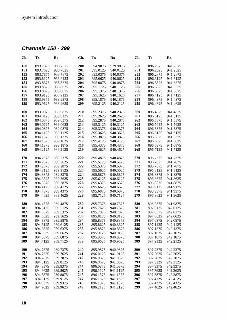
Channels 150 - 299
Ch. Tx Rx Ch. Tx Rx Ch. Tx Rx
150 893.7375 938.7375 200 894.9875 939.9875 250 896.2375 941.2375151 893.7625 938.7625 201 895.0125 940.0125 251 896.2625 941.2625152 893.7875 938.7875 202 895.0375 940.0375 252 896.2875 941.2875153 893.8125 938.8125 203 895.0625 940.0625 253 896.3125 941.3125154 893.8375 938.8375 204 895.0875 940.0875 254 896.3375 941.3375155 893.8625 938.8625 205 895.1125 940.1125 255 896.3625 941.3625156 893.8875 938.8875 206 895.1375 940.1375 256 896.3875 941.3875157 893.9125 938.9125 207 895.1625 940.1625 257 896.4125 941.4125158 893.9375 938.9375 208 895.1875 940.1875 258 896.4375 941.4375159 893.9625 938.9625 209 895.2125 940.2125 259 896.4625 941.4625
160 893.9875 938.9875 210 895.2375 940.2375 260 896.4875 941.4875161 894.0125 939.0125 211 895.2625 940.2625 261 896.5125 941.5125162 894.0375 939.0375 212 895.2875 940.2875 262 896.5375 941.5375163 894.0625 939.0625 213 895.3125 940.3125 263 896.5625 941.5625164 894.0875 939.0875 214 895.3375 940.3375 264 896.5875 941.5875165 894.1125 939.1125 215 895.3625 940.3625 265 896.6125 941.6125166 894.1375 939.1375 216 895.3875 940.3875 266 896.6375 941.6375167 894.1625 939.1625 217 895.4125 940.4125 267 896.6625 941.6625168 894.1875 939.1875 218 895.4375 940.4375 268 896.6875 941.6875169 894.2125 939.2125 219 895.4625 940.4625 269 896.7125 941.7125
170 894.2375 939.2375 220 895.4875 940.4875 270 896.7375 941.7375171 894.2625 939.2625 221 895.5125 940.5125 271 896.7625 941.7625172 894.2875 939.2875 222 895.5375 940.5375 272 896.7875 941.7875173 894.3125 939.3125 223 895.5625 940.5625 273 896.8125 941.8125174 894.3375 939.3375 224 895.5875 940.5875 274 896.8375 941.8375175 894.3625 939.3625 225 895.6125 940.6125 275 896.8625 941.8625176 894.3875 939.3875 226 895.6375 940.6375 276 896.8875 941.8875177 894.4125 939.4125 227 895.6625 940.6625 277 896.9125 941.9125178 894.4375 939.4375 228 895.6875 940.6875 278 896.9375 941.9375179 894.4625 939.4625 229 895.7125 940.7125 279 896.9625 941.9625
180 894.4875 939.4875 230 895.7375 940.7375 280 896.9875 941.9875181 894.5125 939.5125 231 895.7625 940.7625 281 897.0125 942.0125182 894.5375 939.5375 232 895.7875 940.7875 282 897.0375 942.0375183 894.5625 939.5625 233 895.8125 940.8125 283 897.0625 942.0625184 894.5875 939.5875 234 895.8375 940.8375 284 897.0875 942.0875185 894.6125 939.6125 235 895.8625 940.8625 285 897.1125 942.1125186 894.6375 939.6375 236 895.8875 940.8875 286 897.1375 942.1375187 894.6625 939.6625 237 895.9125 940.9125 287 897.1625 942.1625188 894.6875 939.6875 238 895.9375 940.9375 288 897.1875 942.1875189 894.7125 939.7125 239 895.9625 940.9625 289 897.2125 942.2125
190 894.7375 939.7375 240 895.9875 940.9875 290 897.2375 942.2375191 894.7625 939.7625 241 896.0125 941.0125 291 897.2625 942.2625192 894.7875 939.7875 242 896.0375 941.0375 292 897.2875 942.2875193 894.8125 939.8125 243 896.0625 941.0625 293 897.3125 942.3125194 894.8375 939.8375 244 896.0875 941.0875 294 897.3375 942.3375195 894.8625 939.8625 245 896.1125 941.1125 295 897.3625 942.3625196 894.8875 939.8875 246 896.1375 941.1375 296 897.3875 942.3875197 894.9125 939.9125 247 896.1625 941.1625 297 897.4125 942.4125198 894.9375 939.9375 248 896.1875 941.1875 298 897.4375 942.4375199 894.9625 939.9625 249 896.2125 941.2125 299 897.4625 942.4625

System Introduction
19
Channels 300 - 449
Ch. Tx Rx Ch. Tx Rx Ch. Tx Rx
300 897.4875 942.4875 350 898.7375 943.7375 400 899.9875 944.9875301 897.5125 942.5125 351 898.7625 943.7625 401 900.0125 945.0125302 897.5375 942.5375 352 898.7875 943.7875 402 900.0375 945.0375303 897.5625 942.5625 353 898.8125 943.8125 403 900.0625 945.0625304 897.5875 942.5875 354 898.8375 943.8375 404 900.0875 945.0875305 897.6125 942.6125 355 898.8625 943.8625 405 900.1125 945.1125306 897.6375 942.6375 356 898.8875 943.8875 406 900.1375 945.1375307 897.6625 942.6625 357 898.9125 943.9125 407 900.1625 945.1625308 897.6875 942.6875 358 898.9375 943.9375 408 900.1875 945.1875309 897.7125 942.7125 359 898.9625 943.9625 409 900.2125 945.2125
310 897.7375 942.7375 360 898.9875 943.9875 410 900.2375 945.2375311 897.7625 942.7625 361 899.0125 944.0125 411 900.2625 945.2625312 897.7875 942.7875 362 899.0375 944.0375 412 900.2875 945.2875313 897.8125 942.8125 363 899.0625 944.0625 413 900.3125 945.3125314 897.8375 942.8375 364 899.0875 944.0875 414 900.3375 945.3375315 897.8625 942.8625 365 899.1125 944.1125 415 900.3625 945.3625316 897.8875 942.8875 366 899.1375 944.1375 416 900.3875 945.3875317 897.9125 942.9125 367 899.1625 944.1625 417 900.4125 945.4125318 897.9375 942.9375 368 899.1875 944.1875 418 900.4375 945.4375319 897.9625 942.9625 369 899.2125 944.2125 419 900.4625 945.4625
320 897.9875 942.9875 370 899.2375 944.2375 420 900.4875 945.4875321 898.0125 943.0125 371 899.2625 944.2625 421 900.5125 945.5125322 898.0375 943.0375 372 899.2875 944.2875 422 900.5375 945.5375323 898.0625 943.0625 373 899.3125 944.3125 423 900.5625 945.5625324 898.0875 943.0875 374 899.3375 944.3375 424 900.5875 945.5875325 898.1125 943.1125 375 899.3625 944.3625 425 900.6125 945.6125326 898.1375 943.1375 376 899.3875 944.3875 426 900.6375 945.6375327 898.1625 943.1625 377 899.4125 944.4125 427 900.6625 945.6625328 898.1875 943.1875 378 899.4375 944.4375 428 900.6875 945.6875329 898.2125 943.2125 379 899.4625 944.4625 429 900.7125 945.7125
330 898.2375 943.2375 380 899.4875 944.4875 430 900.7375 945.7375331 898.2625 943.2625 381 899.5125 944.5125 431 900.7625 945.7625332 898.2875 943.2875 382 899.5375 944.5375 432 900.7875 945.7875333 898.3125 943.3125 383 899.5625 944.5625 433 900.8125 945.8125334 898.3375 943.3375 384 899.5875 944.5875 434 900.8375 945.8375335 898.3625 943.3625 385 899.6125 944.6125 435 900.8625 945.8625336 898.3875 943.3875 386 899.6375 944.6375 436 900.8875 945.8875337 898.4125 943.4125 387 899.6625 944.6625 437 900.9125 945.9125338 898.4375 943.4375 388 899.6875 944.6875 438 900.9375 945.9375339 898.4625 943.4625 389 899.7125 944.7125 439 900.9625 945.9625
340 898.4875 943.4875 390 899.7375 944.7375 440 900.9875 945.9875341 898.5125 943.5125 391 899.7625 944.7625 441 901.0125 946.0125342 898.5375 943.5375 392 899.7875 944.7875 442 901.0375 946.0375343 898.5625 943.5625 393 899.8125 944.8125 443 901.0625 946.0625344 898.5875 943.5875 394 899.8375 944.8375 444 901.0875 946.0875345 898.6125 943.6125 395 899.8625 944.8625 445 901.1125 946.1125346 898.6375 943.6375 396 899.8875 944.8875 446 901.1375 946.1375347 898.6625 943.6625 397 899.9125 944.9125 447 901.1625 946.1625348 898.6875 943.6875 398 899.9375 944.9375 448 901.1875 946.1875349 898.7125 943.7125 399 899.9625 944.9625 449 901.2125 946.2125

System Introduction
20
Channels 450 - 600
Ch. Tx Rx Ch. Tx Rx Ch. Tx Rx
450 901.2375 946.2375 500 902.4875 947.4875 550 903.7375 948.7375451 901.2625 946.2625 501 902.5125 947.5125 551 903.7625 948.7625452 901.2875 946.2875 502 902.5375 947.5375 552 903.7875 948.7875453 901.3125 946.3125 503 902.5625 947.5625 553 903.8125 948.8125454 901.3375 946.3375 504 902.5875 947.5875 554 903.8375 948.8375455 901.3625 946.3625 505 902.6125 947.6125 555 903.8625 948.8625456 901.3875 946.3875 506 902.6375 947.6375 556 903.8875 948.8875457 901.4125 946.4125 507 902.6625 947.6625 557 903.9125 948.9125458 901.4375 946.4375 508 902.6875 947.6875 558 903.9375 948.9375459 901.4625 946.4625 509 902.7125 947.7125 559 903.9625 948.9625
460 901.4875 946.4875 510 902.7375 947.7375 560 903.9875 948.9875461 901.5125 946.5125 511 902.7625 947.7625 561 904.0125 949.0125462 901.5375 946.5375 512 902.7875 947.7875 562 904.0375 949.0375463 901.5625 946.5625 513 902.8125 947.8125 563 904.0625 949.0625464 901.5875 946.5875 514 902.8375 947.8375 564 904.0875 949.0875465 901.6125 946.6125 515 902.8625 947.8625 565 904.1125 949.1125466 901.6375 946.6375 516 902.8875 947.8875 566 904.1375 949.1375467 901.6625 946.6625 517 902.9125 947.9125 567 904.1625 949.1625468 901.6875 946.6875 518 902.9375 947.9375 568 904.1875 949.1875469 901.7125 946.7125 519 902.9625 947.9625 569 904.2125 949.2125
470 901.7375 946.7375 520 902.9875 947.9875 570 904.2375 949.2375471 901.7625 946.7625 521 903.0125 948.0125 571 904.2625 949.2625472 901.7875 946.7875 522 903.0375 948.0375 572 904.2875 949.2875473 901.8125 946.8125 523 903.0625 948.0625 573 904.3125 949.3125474 901.8375 946.8375 524 903.0875 948.0875 574 904.3375 949.3375475 901.8625 946.8625 525 903.1125 948.1125 575 904.3625 949.3625476 901.8875 946.8875 526 903.1375 948.1375 576 904.3875 949.3875477 901.9125 946.9125 527 903.1625 948.1625 577 904.4125 949.4125478 901.9375 946.9375 528 903.1875 948.1875 578 904.4375 949.4375479 901.9625 946.9625 529 903.2125 948.2125 579 904.4625 949.4625
480 901.9875 946.9875 530 903.2375 948.2375 580 904.4875 949.4875481 902.0125 947.0125 531 903.2625 948.2625 581 904.5125 949.5125482 902.0375 947.0375 532 903.2875 948.2875 582 904.5375 949.5375483 902.0625 947.0625 533 903.3125 948.3125 583 904.5625 949.5625484 902.0875 947.0875 534 903.3375 948.3375 584 904.5875 949.5875485 902.1125 947.1125 535 903.3625 948.3625 585 904.6125 949.6125486 902.1375 947.1375 536 903.3875 948.3875 586 904.6375 949.6375487 902.1625 947.1625 537 903.4125 948.4125 587 904.6625 949.6625488 902.1875 947.1875 538 903.4375 948.4375 588 904.6875 949.6875489 902.2125 947.2125 539 903.4625 948.4625 589 904.7125 949.7125
490 902.2375 947.2375 540 903.4875 948.4875 590 904.7375 949.7375491 902.2625 947.2625 541 903.5125 948.5125 591 904.7625 949.7625492 902.2875 947.2875 542 903.5375 948.5375 592 904.7875 949.7875493 902.3125 947.3125 543 903.5625 948.5625 593 904.8125 949.8125494 902.3375 947.3375 544 903.5875 948.5875 594 904.8375 949.8375495 902.3625 947.3625 545 903.6125 948.6125 595 904.8625 949.8625496 902.3875 947.3875 546 903.6375 948.6375 596 904.8875 949.8875497 902.4125 947.4125 547 903.6625 948.6625 597 904.9125 949.9125498 902.4375 947.4375 548 903.6875 948.6875 598 904.9375 949.9375499 902.4625 947.4625 549 903.7125 948.7125 599 904.9625 949.9625
600 904.9875 949.9875

Technical DescriptionEricsson Mobile Phone EF738

Technical Description
2

Technical Description
3
Contents
Overview __________________________________________ 7Basic Building Blocks ______________________________________ 8Transceiver Block Diagram _________________________________ 9PCB ____________________________________________________ 10
Mechanical Design __________________________________11
Man Machine Interface (MMI)_______________________ 12Keypad _________________________________________________ 12Display _________________________________________________ 12Acoustic Signals __________________________________________ 12Top LED Indicator _______________________________________ 12
Radio Design ______________________________________ 13General Overview ________________________________________ 13
Antenna Connector ___________________________________________ 13Antenna Filters ______________________________________________ 13Receiver Part________________________________________________ 14
Receiver Front End ________________________________________ 14IF Part __________________________________________________ 14Receiver Back-End ________________________________________ 15
Synthesizer _________________________________________________ 16Programming _____________________________________________ 16Power___________________________________________________ 16Lock Detect ______________________________________________ 16
VCTCXO __________________________________________________ 17Transmitter _________________________________________________ 18
TX Blocks _______________________________________________ 18MALIN ____________________________________________________ 19
TX-IF VCO ______________________________________________ 19TX Mixer________________________________________________ 19TX Modulation ___________________________________________ 19TX-IF Frequency Control ___________________________________ 19Programmable Prescaler ____________________________________ 19
Power and Charging Design _________________________ 20Regulators ______________________________________________ 20Reset ___________________________________________________ 21On/Off Control __________________________________________ 21Charging Circuitry _______________________________________ 21Transient/ESD Protection__________________________________ 22Off Current Draw ________________________________________ 22
User Interface _____________________________________ 23Illumination _____________________________________________ 23Buzzer__________________________________________________ 23LCD Display_____________________________________________ 23Keypad _________________________________________________ 23
Continued on next page
Technical Description
4
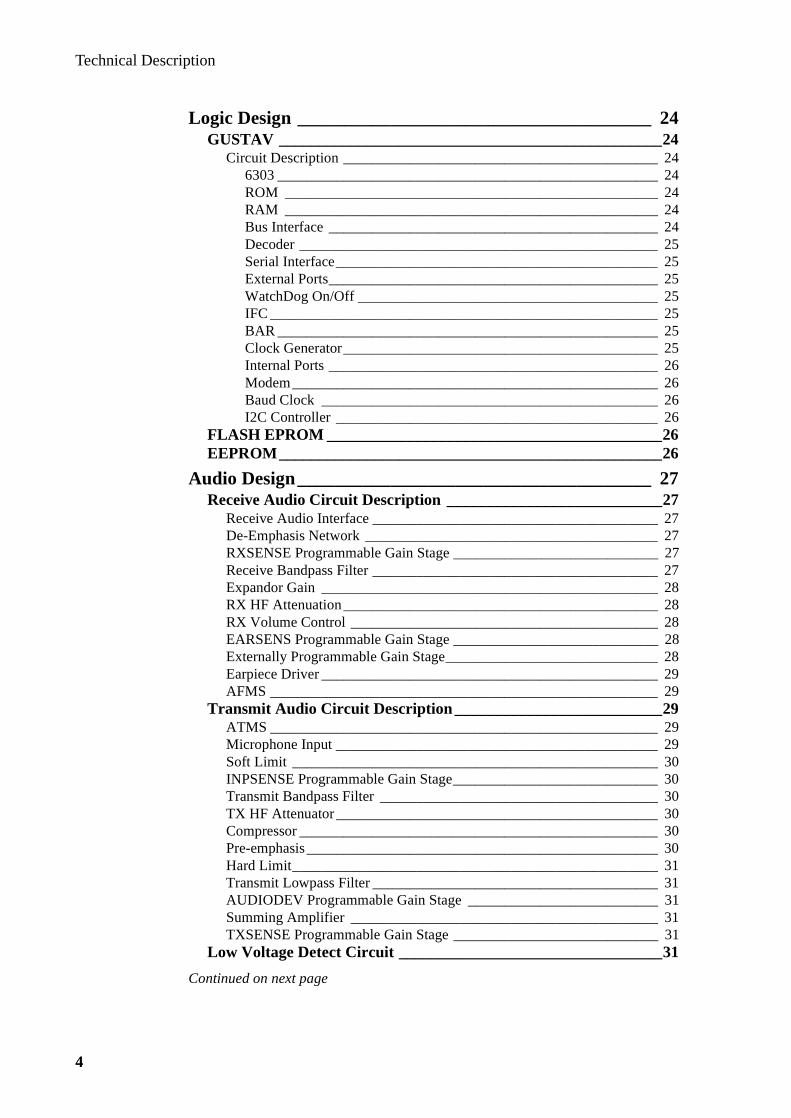
Logic Design ______________________________________ 24GUSTAV ________________________________________________24
Circuit Description ___________________________________________ 246303 ____________________________________________________ 24ROM ___________________________________________________ 24RAM ___________________________________________________ 24Bus Interface _____________________________________________ 24Decoder _________________________________________________ 25Serial Interface____________________________________________ 25External Ports_____________________________________________ 25WatchDog On/Off _________________________________________ 25IFC _____________________________________________________ 25BAR ____________________________________________________ 25Clock Generator___________________________________________ 25Internal Ports _____________________________________________ 26Modem__________________________________________________ 26Baud Clock ______________________________________________ 26I2C Controller ____________________________________________ 26
FLASH EPROM __________________________________________26EEPROM________________________________________________26
Audio Design______________________________________ 27Receive Audio Circuit Description ___________________________27
Receive Audio Interface _______________________________________ 27De-Emphasis Network ________________________________________ 27RXSENSE Programmable Gain Stage ____________________________ 27Receive Bandpass Filter _______________________________________ 27Expandor Gain ______________________________________________ 28RX HF Attenuation___________________________________________ 28RX Volume Control __________________________________________ 28EARSENS Programmable Gain Stage ____________________________ 28Externally Programmable Gain Stage_____________________________ 28Earpiece Driver ______________________________________________ 29AFMS _____________________________________________________ 29
Transmit Audio Circuit Description__________________________29ATMS _____________________________________________________ 29Microphone Input ____________________________________________ 29Soft Limit __________________________________________________ 30INPSENSE Programmable Gain Stage____________________________ 30Transmit Bandpass Filter ______________________________________ 30TX HF Attenuator____________________________________________ 30Compressor _________________________________________________ 30Pre-emphasis________________________________________________ 30Hard Limit__________________________________________________ 31Transmit Lowpass Filter _______________________________________ 31AUDIODEV Programmable Gain Stage __________________________ 31Summing Amplifier __________________________________________ 31TXSENSE Programmable Gain Stage ____________________________ 31
Low Voltage Detect Circuit _________________________________31
Continued on next page

Technical Description
5
RX and TX Sat Circuits ___________________________________ 32RX SAT Filter ______________________________________________ 32RX SAT Schmit Trigger_______________________________________ 32TX SAT Filter_______________________________________________ 32TX SATDEV Programmable Gain Stage__________________________ 32
8Kbit/s Manchester Data Circuit____________________________ 32Data Filter __________________________________________________ 32DATADEV Programmable Gain Stage ___________________________ 32
HandsFree Circuit________________________________________ 32
Software Design ___________________________________ 33Power Down Control______________________________________ 33Timing and Operation_____________________________________ 33
Main Modes of Operation______________________________________ 33Power Saving Sleep Function___________________________________ 33
Software Assignments _____________________________________ 33
Technical Specifications_____________________________ 34General ____________________________________________________ 34Transmitter _________________________________________________ 34Receiver ___________________________________________________ 34

Technical Description
6

Technical Description
7
Overview
The Ericsson EF738 Mobile Phone is a small, lightweight phone operating at 3.8V. It is a class 4 cellular telephone that is fully compatible with the ETACS system with extended frequencies.
The EF738 includes the following three exterior parts:
• telephone section (incl. keypad, character display, earpiece, microphone and flip)
• removable battery
• removable antenna
Figure 1: The Ericsson Mobile Phone EF738
Technical Description
8
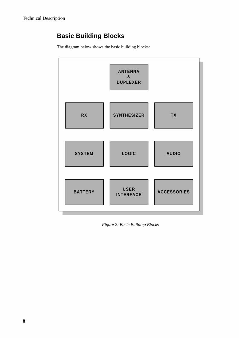
Basic Building Blocks
The diagram below shows the basic building blocks:
Figure 2: Basic Building Blocks
LOGIC
RX SYNTHESIZER TX
AUDIO
BATTERY ACCESSORIESUSER
INTERFACE
ANTENNA&
DUPLEXER
SYSTEM

Technical Description
9
Transceiver Block Diagram
The transceiver (transmitter/receiver) consist of a digital part that controls and supervises transmission/reception on the radio channel. It also handles keyboard, display and protocol transmission to the MTX (Mobile Telephone eXchange). The audio part controls audio signals for earphone, microphone and modem.
Figure 3: Transceiver Block Diagram
TRANSMITTERFREQ. GENERATOR
MOD. RECEIVER
AUDIO PROCESSINGMICRO/LOUDSPKR
CPUMEMORIES
On/Off
KEYPADDISPLAY
EXTERNAL
CONNECTOR
LOGIC
MMI
RADIO
mod discr
control bus
ATMS/AFMS

Technical Description
10
PCB
The printed circuit board is a 6-layer PCB where all components are located inlayer 1 (primary side) and layer 6 (secondary side).Layers 2 and 5 are ground planes and layers 3 and 4 are used for signal conducting.
Primary Side Secondary Side
Figure 4: PCB LayOut
SYSTEM CONNECTOR
FLASH EE-PROM
ANTON
GUSTAV
BERT-INDY
MIA
BATCON
IF PART
MALIN
VCTCXO
RECEIVER VCO
ANT DUPLEXER
SYSTEM CONNECTOR
KEYPAD
TRANSMITTER
BUZZER
VOL
VOL

Technical Description
11
Mechanical Desi gn
The phone is designed as a ‘brick’ with a mechanical assembly consisting mainly of:
• plastic front cover
• plastic rear cover
• plastic flip
• keyboard
• system connector
• LCD light guide
• metallic plastic for PCB shielding
It has been designed for easy assembly with 6 screws.An optional clip can be mounted into the rear cover.
Figure 5: Mechanical Assembly

Technical Description
12
Man Machine Interface (MMI)
Keypad
The keypad has back-lighting that makes it possible to operate the station in the dark. The back lighting function (on 10sec/on 20sec/off) is selected by the user.
Note that the END/PWR/NO key is not part of the keyboard scanning matrix. It is connected to the 3.8V regulators enable inputs so that the power of GUSTAV is forced On when this key is held down.
The volume keys are not located on the keypad. They are push button switches mounted on the upper left hand side of the phone.
Display
The segmented LCD contains one row of 10 alpha-numeric characters and one row of icons.
The software for driving the display is contained in the Flash EPROM.An elastomeric connector joins the PCB to the transparent conductive tracks on the LCD module.
Acoustic Signals
The acoustic signals are generated by a buzzer in the transceiver. The acoustic level as well as the frequency of the signal is variable in order to distinguish between dif-ferent situations.
The different acoustic signals are:
• Ring signals
• Alarm signals
• Low battery warning
• Keypad tone or “click”
Top LED Indicator
A dual-colour LED (green & red) is positioned on the top front end.Each LED is connected to a separate output port on GUSTAV.Blinking rates and color of the Indicator LED are controlled by software.

Technical Description
13
Radio Desi gn
General Overview
The radio operates on the ETACS frequency band. The transmitter operates at 872.0125 MHz to 905.9875 MHz and the receiver at 917.0125 MHz to 949.9875 MHz. The duplex spacing is 45MHz and the channel separation is 25KHz.
Together with the logic/audio part the radio fulfills the ETACS requirements.
Antenna Connector
The antenna connector consists of a mechanical assembly that connects the antenna to the radio. The impedance of the antenna connector is 50Ω.
Antenna Filters
The duplex filter consists of a 4-pole TX section of band pass characteristic with a notch at the RX frequency and a 4-pole RX section filter with 50Ω impedance in each direction.
The task for the TX filter is to suppress wide band noise evolving from the VCO and the power amplifier on RX frequencies.
The task for the RX branch is to suppress the transmitter signal to a level low enough not to overdrive the receiver front end amplifier and attenuate external spu-rious signals.The RX-section also suppresses leakage from the local oscillator.
Figure 6: Radio Block Diagram
Audio In
Audio Out
450KHz
44.55MHz
45MHz
962-995MHz
TX TX MIXER TX SYNTH
POWERCONTROL
DUPLEXFILTER
FRONTEND
RX SYNTH
VCTCXO14.85MHz
RADIO IFBERTINDY
IF
Bus Control

Technical Description
14
Receiver Part
The front-end stage is the first link in the receiver chain. It’s purpose is to amplify the RF and down-convert it to the 1st IF frequency and to set the RX system noise figure. The desired input frequencies are within the range 917.0125 to 949.9875 MHz. The selected frequency is down-converted to 45 MHz and amplified. This section includes a low-voltage RX front-end chip, “Low-voltage ANNIKA”, com-prised of a low noise amplifier, a mixer, and the 1st image filter.
Receiver Front End
ANNIKA: RF-amplifier
The input of the integrated low-noise amplifier is matched for optimal performance regarding minimum noise level and second order intermodulation performance.It also provides a 50Ω load to the duplexer.
BP-filter
This bandpass filter is a SAW filter needed for spurious response rejection (suppres-sion of the first image frequency). The filter also suppresses the local oscillator backwards to the antenna.
ANNIKA: Mixer
The integrated mixer in the same package as the LNA includes an internal buffer for the Local Oscillator (LO) which allows low LO input power and immunity from variations in LO input power. At the RF port, an inductor rejects the noise coming to the mixer directly at the IF band. The output of the mixer is converted to a higher impedance to match the crystal filter in the following IF circuitry.
IF Part
The IF/AF part is the second link in the receiver chain. It performs the major part of the RF amplification and all the channel filtering. The 1st IF at 45 MHz is down-converted to 450 KHz and FM demodulated in Bertindy. The IF IC generates a DC voltage (RSSI), which is logarithmically proportional to the strength of the received signal.
Figure 7: IF/AF Link
2nd LOfrom
BERTINDY
1st450KHz
Filter
2nd450KHz
Filter45MHzFilter
FromANNIKA
Mixer
2nd Mixer IF Amp Limiter
ToDigit Discr
&De-Emphasis(BERTINDY)
IF/AF IC

Technical Description
15
Receiver Back-End
The IF/AF circuit is an integrated bipolar circuit containing a mixer, IF amplifier, limiter, RSSI circuits, and FM detection circuit. The rest of the required functions are located in BERTINDY.
The 1st IF frequency of 45 MHz is fed to the 2nd mixer where it is down-converted to 450 KHz (2nd IF) in the IC. The 2nd LO signal at 44.55 MHz for the mixer comes from BERTINDY. Third harmonic of the reference oscillator frequency (14.85 MHz) is used as the 2nd LO signal.
The 450 KHz signal is filtered through a ceramic 2nd IF filter and fed to the input of the IF amplifier stage. The output signal from this stage is filtered through a second ceramic 2nd IF filter and is then applied to the limiter. The resulting 450 KHz square-wave signal is fed to the digital discriminator in BERTINDY where it is demodulated and de-emphasized before being passed to the ANTON IC for further audio processing.
Band Pass 1st IF Filter (2nd Image Filter)
This crystal filter is needed for spurious response rejection (suppression of the 2nd image frequency) and inter-modulation rejection. The crystal filter is a band pass filter with a center frequency of 45 MHz. Some channel filtering is also performed in this filter.
Channel and Noise Reduction Filters
Two bandpass 2nd IF filters are needed for broadband noise reduction and desired channel selection. Each filter is a ceramic 4-pole bandpass filter with a center fre-quency of 450 KHz.
450 KHz Output
From the limiter output, the 450 KHz square-wave signal is fed to the digital dis-criminator in BERTINDY for demodulation. This signal is also used by the AFC algorithm in determining the frequency error of the 14.85 MHz reference relative to the received signal.
RSSI Output
A voltage which is logarithmically proportional to the RF input power of the received signal is produced in the IF/AF IC.
RSSI Range
The lower end of the useable range is controlled primarily by the RF/IF gain of the receiver while the upper end of the RSSI voltage is controlled by the supply voltage of the IF/AF chip.

Technical Description
16
Synthesizer
A 900 MHz RX synthesizer is used as first LO. The TX synthesizer is modulated and working at a fixed frequency of 90 MHz. The TX frequency is obtained by mix-ing the frequencies from the two synthesizers.
The main synthesizer uses fractional-N to achieve lower phase noise and faster switching. In most applications the phase noise is proportional to the overall divi-sion ratio and since fractional-N uses a higher comparison frequency the phase noise will be lower.
The auxiliary synthesizer is a conventional loop without fractional-N and the com-parison frequency is 75 KHz.
The RX VCO is a module which operates between 914.040 MHz and 938.970 MHz.
The MALIN chip contains the TX VCO , TX buffer stage, TX mixer, RX buffer stage and the RX prescaler.
The TX PLL, RX PLL and the lock detect logic are part of the BERTINDY chip.
Programming
The name of the PLL circuit is BERTINDY, which is a combination of the two chips Bertram and Cindy. A three line bus is used to program the synthesizer with the help of a clock frequency. The RX synthesizer is operating at 45 MHz above the required RX frequency and a 14.85 MHz reference frequency is used.
Power
The synthesizer part in BERTINDY is put in power down mode by sending a com-mand to the chip. The auxiliary and main synthesizer can be powered down sepa-rately and the RX-VCO is controlled by BERTINDY. The prescaler and the 90 MHz VCO of MALIN is controlled by sending power up/down commands.
Lock Detect
A signal showing when the synthesizer is locked is implemented in BERTINDY. The lock detect circuit operates with both the main and the auxiliary synthesizers. If both synthesizers are enabled, the lock detect output becomes active when they are both locked. If only one synthesizer is enabled, the lock detect output becomes active when that one is locked.

Technical Description
17
VCTCXO
The task of the VCTCXO is to supply the synthesizer with a stable, accurate refer-ence frequency. A 14.85 MHz crystal with DAC-controlled varactor diodes and a transistor stage within BERTINDY constitues the TCXO circuit. A software algo-rithm is used for temperature compensation as well as an AFC function.
The operating frequency of the synthesizer reference oscillator is set by the crystal element. The crystal is specified for a resonant frequency of 14.85 MHz at a specific load capacitance. Tuning of the series resonance frequency is accomplished by adjusting the total series capacitance seen by the crystal. Varactor diodes provide the method of varying the load capacitance posed to the crystal. Both varactors are con-trolled by DAC’s within BERTINDY. DAC1 is the “fine tune” adjustment, and DAC2 is the “coarse tune” adjustment.
Initial trimming for component tolerances is done by DAC2 in the factory. In the field, the TCXO is adjusted mainly through DAC1 for temperature compensation and AFC. DAC2 is only adjusted in the field when necessary to maintain the fullest DAC1 range possible. This is where the integer ratio of tuning sensitivity is desira-ble.
The inherent frequency deviations of the crystal when operated over the full temper-ature range are corrected by a software controlled temperature compensation algo-rithm. A look-up table is stored in memory which is indexed by temperature readings from a signal originating from a thermistor voltage divider network. This is the only means for frequency compensation in the field when the down link signal from the base station is weak and below the AFC threshold. When the base station signal is above the threshold (roughly -110 dBm), and when the phone is in either idle or conversation mode, the AFC algorithm is enabled. The temperature compen-sation table ensures that the TCXO frequency will be kept close enough to lock to the base station signal and null out frequency error once the proper conditions are met.

Technical Description
18
Transmitter
The transmitter section amplifies the transmitter signal from approximately0.25 mW to 1.25 W. This section is compound by a driver stage and a power ampli-fier.Output power is regulated by a closed feedback loop incorporating a stripline cou-pler, Schottky rectifier diode, and a power amplifier with high and variable gain and high efficiency.
TX Blocks
TX Driver Amplifier
The transistor used is a bipolar type in a common emitter configuration, which offers unconditional stability and good dynamic range.The output and inputs are matched to 50Ω, and there is an attenuation at the output to avoid damage in PA.
Power Amplifier Module
The output power of the PA-module is varied by controlling the bias point. The sat-urated output power of the PA is dependent upon the load presented at its output. For the required saturated output power and efficiency, a specified load must be used.
Power Detector
The power sensing is done with a coupled stripline detector. This circuit senses for-ward power with some directionality. A Schottky diode is used to rectify the RF and this diode is forward biased to avoid having the diode snap off when detecting low levels of RF. Direct temperature compensation is achieved by providing the detector bias voltage via a matched diode
Power Control
The output power from the power amplifier is regulated by an active feedback loop. The reference value is set via a D/A-converter in BERTINDY and is connected to the positive input of an op-amp, where the detected output power level is connected to the negative input of the same op-amp. The op-amp produces an error voltage that controls the base current of a transistor, which in turn varies the output level of the PA.
Figure 8: Transmitter Block Diagram
AttenuatorTX
FilterDuplexer CouplerPower
AmpDriver Antenna
Rectifier PowerControl
F _ T X
PowerLeve l

Technical Description
19
TX Filtering
The reduction of TX spurious emissions and TX noise in the RX band is achieved with two filters. The first is a bandpass SAW filter. The second filter is the TX branch of the duplexer filter. The response is predominately band-pass with a notch in the RX band to protect the receiver from TX noise power. High frequency attenu-ation provides reduction in the level of TX harmonics.
Protection against Electro-Static Discharge (ESD) is also provided by the high-pass element of the duplexer TX branch.
MALIN
MALIN, is an integrated RF circuit for FDMA cellular telephones. The circuit is designed for a radio architecture using one synthesizer for both RX and TX parts. The transmitter portion consists of a TX-IF VCO and a TX-mixer. The base-band signal modulates the TX-IF via an external tank circuit which is then up-converted to the TX frequency by the TX-mixer. A programmable prescaler is included for use in the main synthesizer loop, and power down control is provided for current saving.
TX-IF VCO
The TX-IF is generated by an internal oscillator of MALIN. Tuning is performed by an external tank circuit where the center frequency is controlled by the auxiliary synthesizer using a varactor diode. The TX-IF signal is also buffered and sent to the auxiliary synthesizer to maintain a constant 90 MHz TX-IF frequency.
TX Mixer
The TX mixer multiplies the TX-IF signal with the first LO signal from the main VCO to create the desired output signal. The mixer is designed to have a low noise floor in order not to affect the receiver performance. The output is differential and an LC network is used to align the signals to make them combine constructively.
TX Modulation
The modulation of the transmitter occurs in the TX-IF VCO tank circuit. The base-band signal coming from the audio IC ANTON is filtered and used to shift the reso-nant frequency of the external tank circuit by the varying capacitance of the varactor diode.
TX-IF Frequency Control
The center frequency of the TX-IF VCO is controlled by the auxiliary synthesizer located in BERTINDY. A portion of the TX-IF signal is buffered and sent to the TX oscillator outputs. This signal is used to lock the TX-IF in the Auxiliary PLL.
Programmable Prescaler
MALIN also includes a prescaler for use in the main synthesizer loop. The divider has separate Vcc and ground connections to provide good isolation from the TXPA outputs.
Technical Description
20
Power and Char ging Design
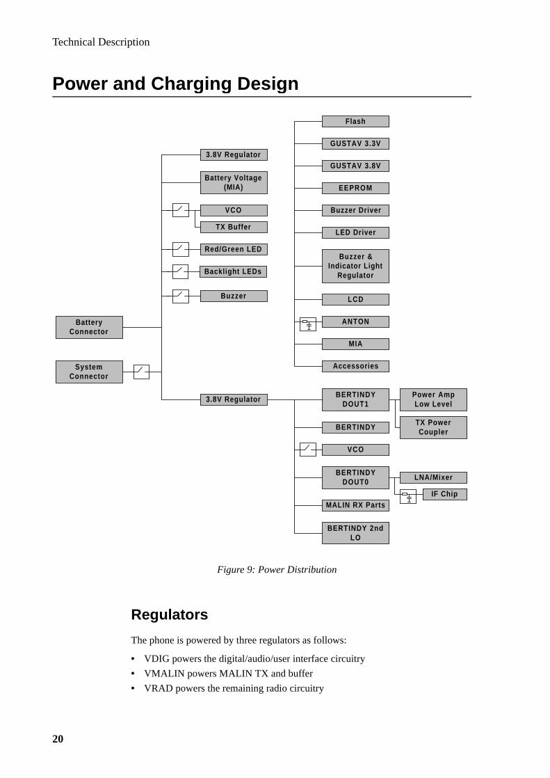
Regulators
The phone is powered by three regulators as follows:
• VDIG powers the digital/audio/user interface circuitry
• VMALIN powers MALIN TX and buffer
• VRAD powers the remaining radio circuitry
Figure 9: Power Distribution
Flash
GUSTAV 3.3V
GUSTAV 3.8V
EEPROM
Buzzer Driver
LED Driver
Buzzer &Indicator Light
Regulator
LCD
ANTON
MIA
Accessories
BERTINDYDOUT1
BERTINDY
VCO
BERTINDYDOUT0
MALIN RX Parts
BERTINDY 2ndLO
Power AmpLow Level
TX PowerCoupler
LNA/Mixer
IF Chip
3.8V Regulator
SystemConnector
BatteryConnector
3.8V Regulator
Battery Voltage(MIA)
TX Buffer
VCO
Red/Green LED
Backlight LEDs
Buzzer

Technical Description
21
The regulators have got an enable input, which is used to power the phone on/off. The minimum voltage for turning the regulators on is 2.0V, and the maximum for turning them off is 0.18V.
Reset
The digital voltage VDIG is monitored by a low voltage detector in ANTON. While the phone is operating, and if VDIG drops below 3.35V (typical), ANTON’s LVN open-drain output will set GUSTAV’s reset input (MRN) low, causing the processor to reset. Upon power-up, an RC filter holds GUSTAV’s reset input low for the required 20 ms delay.
On/Off Control
The phone may be powered on by either pressing the ON/OFF/END key, or by applying 7.0V-10.0V at DCIO.
When the ON/OFF/END key is pressed for at least 200 ms, this key powers on the phone by connecting the battery voltage to the enable inputs of the regulators through a diode. The processor then comes out of reset and latches the enable inputs of the regulators.
Chargers and accessories power on the phone by applying 7.0V-10.0V at DCIO. The voltage difference between DCIO and the battery voltage turns on a transistor connected to the enable inputs of the regulators. As with the ON/OFF/END key, the DCIO voltage must be present for at least 200 ms in order to power on the phone.
If no charger is connected, the phone is powered-off by pressing and then releasing the ON/OFF/END key. Pressing the ON/OFF/END key generates an interrupt to GUSTAV via a transistor. GUSTAV then tries to disable the regulators but these will stay on until the ON/OFF/END key is released. If a charger is connected, the phone will stay on until the processor detects that the charger has been removed (no cur-rent from charger to phone). The phone cannot turn itself off as long as a charger is connected.
Charging Circuitry
The phone software controls charging by turning a FET switch on/off, based on bat-tery voltage and charging current through a 0.1Ω resistor. Chargers are designed to have an open-circuit voltage less than 10V, and supply an average current of approx-imately 700mA when connected to a battery through the FET switch. A resistor allows a dead battery to become trickle charged high enough for the phone to turn on. MIA provides charge switch control and analog outputs corresponding to charger current and battery voltage. These outputs are connected to BERTINDY’s A/D inputs. GUSTAV turns on the charge switch using a current control output port, which is connected to an input of MIA. If the battery voltage is less than 8.0V, the current control port controls the on/off state of the FET switch. If the battery voltage is greater than 8.0V, MIA keeps the charge switch off regardless of the state of the current control port.
Technical Description
22
Transient/ESD Protection
Diodes are used for ESD protection on the System Connector outputs. The inputs have got resistors between the System Connector and the ASIC input ports. Capaci-tors on DCIO prevent spikes caused by charger cable inductance when the charge switch is turned off. They also protect MIA and the FET-switch from ESD and pro-vide de-coupling for voltage ripple. A capacitor and a varistor provide de-coupling and high-voltage / ESD protection on the battery voltage.
Off Current Draw
The current draw when the phone is off should be as low as possible in order to pre-vent low batteries from being too heavily discharged. The only components directly connected to the battery which may draw current when the phone is off are MIA, a low voltage detector, and the regulators.

Technical Description
23
User Interface
Illumination
The phone is illuminated with 14 SMD LED’s, 4 for the display and 10 for the key-board. The LED’s are switched on and off from GUSTAV. A voltage regulating cir-cuit is included which prevents changes in the battery voltage from affecting the backlighting intensity.
Buzzer
The buzzer, which emits the Beep-, Ring- and Alarm signals, is an electromagnetic resonance buzzer with a resonance frequency of about 3 KHz.The sounds are generated in GUSTAV by software control and then fed to the buzzer.
LCD Display
The display is a 1- row segmented LCD which utilizes chip on glass technology for mounting of the driver chip on the LCD module. No negative voltage supply is required for this LCD and no contrast control is needed since the display in EF738 utilizes a technology which provides a wide viewing cone.
Keypad
There is a 5 x 4 keyboard scanning connected to GUSTAV.
A detection signal is set high when the END/PWR/NO key is pressed and by looking at a feed-back signal GUSTAV is informed and turns the phone on.
Technical Description
24
Logic Desi gn
GUSTAV
GUSTAV is a uP ASIC that consists of 15 blocks:
• 6303
• ROM
• RAM
• Bus Interface
• Decoder
• Serial Interface
• External Ports
• Watchdog On/Off
• IFC
• BAR
• Clock Generator
• Internal Ports
• Modem
• Baud Clock
• I2C Controller
Circuit Description
6303
The processor is an 8 bit processor with an asynchronous full duplex serial commu-nication interface, DTMS/DFMS, for external connections.
ROM
There is an internal 512 byte ROM in GUSTAV which holds a Primitive Interface Program, used for code loading into the RAM. After a reset, the CPU will begin executing the code in IROM. If the SERV line is high, the ROM code continues to execute, otherwise the program code in the external EPROM is started.
RAM
There are 6016 bytes of RAM available in GUSTAV. The processor uses this mem-ory as working space when the phone is turned on. When turned off, data that has to be saved will be stored in the EEPROM before turn off.
Bus Interface
The bus interface will provide the data and address lines to the external Flash EPROM and will also handle the internal busses in GUSTAV.

Technical Description
25
Decoder
The decoder in GUSTAV is an address decoder which has outputs for both internal functions and logic control signals such as chip selects (CS), write (W) and output enable (OE).
Serial Interface
The serial interface in GUSTAV has a transmitter block and a receiver block.The transmitter block consists of four write registers, a clock divider, and other logic for generating interrupts and latch signals. Data is transmitted and received via a serial interface data line.
The receiver block consists of three read registers in which the received data may be read one byte at a time by the processor.
External Ports
This block manages the keyboard along with the handling of binary input/output ports where some inputs are connected to the interrupt control block.
WatchDog On/Off
The Watchdog On/Off block in GUSTAV contains the watchdog block and the Autonomous Time Out (ATO) block. This block consists of a four second counter, which when overflown, activates a reset circuit and generates a 100ms reset.
The ATO is a supervising block that monitors the status of the received carrier detect and the transmitter power. If the transmitted power is detected without the received carrier detect for 30 seconds, the ATO initiates a hardware turn off of the phone.
IFC
The IFC counter is used to count a predetermined number of periods of the IF from the radio interface LSI.
BAR
The output from the bar generator is a continuous pulse train with program control-led ON and OFF time. This makes it possible to vary signal parameters such as:
• tone frequency
• signal period
• signal on time
• volume
Clock Generator
The processor clock is generated from an external signal or crystal.An 8.064 MHz clock gives a system clock frequency of 1.008 MHz (or 2.016 MHz in Turbo mode). The serial interface clock will always be 1.008 MHz. The clock generator block has many divider steps to generate all clock frequencies that are required inside GUSTAV and on the logic PCB.

Technical Description
26
Internal Ports
There are three 8 bit read and three 8 bit write ports in this block that are used within GUSTAV.
Modem
The modem part supports two different cellular systems, AMPS and TACS, which consists of data receiver, data transmitter, SAT detector, and SAT transmitter.
The data receiver consists of three parts: digital discriminator, data decoder, and wordsync detector.
The data transmitter sends data bytewise where the most significant bit is transmit-ted first.
The SAT-detection consists of continuous measurements of 10-12 ms and the three frequencies being used are 5970, 6000 and 6030 Hz.
SAT-generation of the three frequencies is also done in GUSTAV.
Baud Clock
This block generates the baud rate for the serial interface of GUSTAV and is select-able among the following baud rates.
600 (Power on default)1200240048009600
I2C Controller
This part controls the communication between the EEPROM and the display.
FLASH EPROM
The system program is stored in a low voltage Flash EPROM with 128k x 8 bit area.
EEPROM
The ‘customer’ PROM is a CMOS EEPROM with 4k x 8 bit area. Data that has to be saved when the station is turned off is stored in this memory, which contains the telephone number, short numbers, talk time, area ID and other radio/audio informa-tion.

Technical Description
27
Audio Desi gn
The baseband audio is processed by ANTON which is a mixed signal ASIC with a compander, filters, limiters and programmable gain blocks.
Receive Audio Circuit Description
Receive Audio Interface
The receive audio is demodulated by a digital discriminator in BERTINDY and then passed through a first order active bandpass filter which is comprised of an op-amp located in BERTINDY. External resistors and capacitors set the gain and bandpass of the filter and the output of this filter is then AC coupled through a capacitor to an external de-emphasis network. The interface between the radio and the baseband audio is between the discriminator’s bandpass filter and the external de-emphasis network.
De-Emphasis Network
The de-emphasis network is composed of two series resistors and a shunt capacitor. The audio is routed through a resistor pair into the receive input port on ANTON. The received SAT is tapped off between the resistor pair and routed to a port on ANTON. The shunt capacitor provides the necessary de-emphasis slope to restore the low frequency components of the audio that were attenuated by the pre-empha-sis in the base station transmit path.
RXSENSE Programmable Gain Stage
The receive audio enters ANTON at the receive input port. The signal first passes through an anti-aliasing filter and is then routed to the RXSENSE programmable gain stage. This gain stage is provided to trim out the tolerances between the dis-criminator output and the expander input. The RXSENSE gain stage has a nominal gain of 8 dB and can be adjusted +6.4/-6.0 dB in steps of +0.4 dB.Test mode 10 ‘RX Sensitivity’ can be used to update this gain stage.
This stage is used to adjust the AFMS level to 25 mVrms with a 1 kHz tone at 2.3 kHz deviation and nominal volume.
Receive Bandpass Filter
The output of the RXSENSE stage is fed into a 300 Hz to 3 kHz switch-capacitor bandpass filter.

Technical Description
28
Expandor Gain
The gain in the expandor is a function of the input signal level with the following relationship for the expandor:
2(X0 - X1 ) = Y0 - Y1
where: X0 = reference input (unaffected level)
Y0 = reference output
X1 = input
Y1 = output
The relationship states that a change in the input from X0 to X1 will produce a change in the output from Y0 to Y1 that equals 1:2.
The gain, A, is then:
A = Y1 - X1 = Y0 - 2X0 +X1
RX HF Attenuation
Following the expander is a 0 to -49 dB attenuator for full duplex handsfree opera-tion. This stage is programmable in steps of 7 dB. When the external audio signal on the system connector is low, the software implements a handsfree algorithm that attenuates the unused audio path to prevent feedback from external speakers to the microphone.
Under normal modes of operation this stage is set to 0 dB. However, during the gen-eration of DTMF tones to the earpiece, this stage is used to attenuate the signal to prevent clipping.
RX Volume Control
The RX audio level is controlled by a 0 to -24 dB gain stage in steps of 3 dB.
EARSENS Programmable Gain Stage
A programmable gain stage is provided to trim the level to the Earpiece to provide 84 dBspl with a 1 kHz tone at 2.3 kHz deviation and max. volume setting (0 dB). This stage is programmable in 0.4 dB steps from -2.8 to 3.2 dBs.
Test Mode 28 ‘Earpiece’ is used to trim this stage.
Externally Programmable Gain Stage
An inverting amplifier follows the EARSENSE stage. The input and feedback ele-ments are external to allow for external programming of gain and filtering.
This stage is bypassed when the earpiece drivers are put in external mode.

Technical Description
29
Earpiece Driver
The earpiece driver is composed of a differential pair, a non-inverting amplifier and an inverting amplifier.
The drivers can be software configured in four modes:
• single-ended
• differential
• external
• muted
A resistor is added in series with the earpiece as a pad to limit the maximum acous-tic level to 103 dBspl. The gains in the ASIC are set to force the signal into clipping at maximum deviation and maximum volume and the excess amplitude is divided down between the resistor and the earpiece.
AFMS
The inverting earpiece amp is used to generate the AFMS signal. The signal is AC coupled to reduce popping when connecting a portable handsfree unit.
Transmit Audio Circuit Description
ATMS
The ATMS signal is AC coupled to the transmit audio path via a capacitor and is then reduced by 2 dB and biased to a voltage. A switch to this voltage is also con-nected to the output of the ATMS port to provide a bias for the portable handsfree microphone. This switch is controlled by the microprocessor, but can be controlled directly by the PORTHF port of the system connector.
Microphone Input
The ASIC has a switchable +22/+32 dB gain stage for amplifying low level micro-phone signals. The ASIC also provides a low noise bias voltage for microphone biasing.
ANTON is designed to provide gain to the portable handsfree microphone by the use of software controlled switches which are located before and after the Mic gain stage, to allow routing of the signal from the ATMS port through the Mic amplifier. The switches can be configured to route the mic audio through the mic amp, to route ATMS through the mic amp or to bypass ATMS around the mic amp. In all three cases, the output of this block is routed to the soft limiter.
Technical Description
30
Soft Limit
A 0 to -30 dB attenuator follows the audio input block where this soft limit is ena-bled through software and is used to limit clipping before the compressor. The soft limit is controlled by two threshold comparators. When the signal exceeds the threshold, a clock will step a tap on a resistor ladder to increase the attenuation.When the level drops below the threshold, a slower clock steps the tap back up the resistor ladder to reduce the attenuation.
INPSENSE Programmable Gain Stage
The soft limit output is AC coupled into the INPSENSE programmable stage and this stage is used to adjust the audio level into the compressor. The gain is pro-grammed through software in a range from +2 to +14.4 dB in steps of 0.8 dB where the nominal setting is +8 dB.
This stage has calibration settings for three modes of operation:
• external audio
• internal audio
• DTMF tones
The three calibration values are stored in the EEPROM.
Transmit Bandpass Filter
The next block in the transmit audio chain is a switched capacitor bandpass filter which is designed to allow frequencies from 300 to 3000 Hz to pass through.
TX HF Attenuator
Following the bandpass filter is a 0 to -49 dB attenuator for full duplex handsfree operation, which is programmable in steps of 7 dB. When the external audio signal on the system connector is low, the software implements a handsfree algorithm that attenuates the unused audio path to prevent feedback from external speakers to microphone.
Compressor
The audio is AC coupled from the transmit handsfree attenuator block into a 2:1 switch capacitor compressor. This stage is enabled during the conversation modes of the phone and can be bypassed for testing.
Test mode 29 has two options for control of the compressor.
An integrator using an amplifier in the ASIC is configured to provide feedback from the output to the input of the compressor.
Pre-emphasis
A 3 dB/Octave high pass filter follows the compressor. This filter is used to equalize the audio spectrum by attenuating the low frequency components of the signal.

Technical Description
31
Hard Limit
A +13.5 dB gain hard limit follows the pre-emphasis block in the transmit audio path in order to limit the maximum audio level out of the ASIC and into the modula-tor block.
Transmit Lowpass Filter
A 3 kHz lowpass filter follows the hard limit to filter out the harmonic components caused by clipping in the hard limit.
AUDIODEV Programmable Gain Stage
The AUDIODEV programmable gain stage follows the TX lowpass filter to allow adjustment of the maximum transmit deviation. This stage is provided to trim out tolerances in the following summing stage.
The nominal gain in the AUDIODEV stage is 0 dB with an adjustment range from +3.2 to -2.8 dB in steps of 0.4 dB.
Test mode 14 can be used to adjust the AUDIODEV stage for TX audio.
The transmitted DTMF tone has a separate setting for AUDIODEV in EEPROM. It needs to be adjusted to provide enough gain after the compressor so that the signal does not clip in the compressor.
Summing Amplifier
The summing amplifier is provided to combine the TX audio / DTMF tone, SAT tone and Manchester data into the modulator. The input resistors and feedback resis-tor for this circuit are external to the ASIC to allow for gain adjustments.
TXSENSE Programmable Gain Stage
The TXSENSE programmable gain stage is an amplifier which is provided to trim out tolerances in the modulator but is currently not used, however set to a default value of 0 dB. This stage has an adjustment range from +3.2 to -2.8 dB with steps of 0.4 dB.
Low Voltage Detect Circuit
A comparator is included in ANTON to provide a reset signal to GUSTAV when the regulated voltage drops below approximately 3.3 V. This circuit is enabled at power up and can be disabled by software to save a small portion of current in standby mode.
Technical Description
32
RX and TX Sat Circuits
RX SAT Filter
A 6 kHz bandpass filter is included to capture the received SAT tone from the com-posite received audio signal
RX SAT Schmit Trigger
The filtered SAT signal is then amplified and routed to a schmit trigger circuit in ANTON where it is squared up and driven to GUSTAV as a digital signal.
TX SAT Filter
The TX SAT signal originates in GUSTAV as a digital signal. The TX SAT filter is a 6 kHz bandpass filter for removal of high order harmonics from the signal.
TX SATDEV Programmable Gain Stage
A programmable gain stage SATDEV is provided to adjust tolerances in the sum-ming circuit to maintain the proper signal level to transmit a 6 kHz SAT tone at 1.7 kHz FM deviation. This gain stage is nominally 0 dB with an adjustment range of +4.8 to -4.5 dB in steps of 0.3 dB.
Test mode 22 can be used to adjust SATDEV.
8Kbit/s Manchester Data Circuit
Data Filter
A 20 kHz lowpass filter is provided to limit the frequency components of the digit-ally generated Manchester data.
Data is transmitted as an 8 kHz signal at 6.2 kHz FM deviation.
DATADEV Programmable Gain Stage
The filtered data signal is routed to a programmable gain stage, DATADEV, for trimming out tolerances in the summing amplifier. The DATADEV gain stage is nominally 0 dB with an adjustment range of +3.2 to -2.8 dB with steps of 0.4 dB.
HandsFree Circuit
ANTON includes rectifier circuits for audio detection in the RX and TX paths.A single port is provided for the monitoring of the rectified signal.A switch is software controlled to select the RX or TX path for sampling.An external capacitor is provided to set the time constant for each path.
Technical Description
33
Software Desi gn
Power Down Control
All voltage regulators are on all the time when in SLEEP, STAND BY and TRANS-MIT mode. The operation modes of ANTON and BERTINDY are software control-led directly from GUSTAV through the serial interface.
Timing and Operation
In the ETACS system it is most important that a well working sleep function can be implemented as this will increase the standby time by several hours.
Main Modes of Operation
The transceiver hardware operation can be split into four main modes: OFF, SLEEP, STAND BY and TRANSMIT.
• OFF is when all regulated power are switched off by the on/off logic. The hard-ware is powered up when the voltage regulators are enabled. At power-up the8 MHz clock frequency synthesizer has to be loaded with the correct division ratios and the RAM has to loaded as well. All software controlled circuits have to be initiated and loaded with their default settings, and then powered down by software until needed again.
• SLEEP mode is the lowest operation mode the transceiver can be put in (excl. OFF mode). All receiver, transmitter and audio circuits are put in power down mode or switched off.
• STAND BY mode is the normal data receive mode, where the transceiver can listen to the data signalling from the base station.
• TRANSMIT mode is the normal conversation/data mode.
Power Saving Sleep Function
When in STAND BY mode the transceiver doesn’t have to be awake listening all the time as there are time slots where the transceiver can be put into SLEEP mode.
Software Assignments
Software is loaded via the serial channel through GUSTAV into the Flash EPROM and the main assignments are:
• controller of the hardware circuitry
• communicator with the cellular system via the RF link
• provider and handler of the operating interface to the user
• provider of test and tune commands for factory and field service
• co-ordinator of the overall system (e.g. operating system)
• controller of the battery charging

Technical Description
34
Technical Specifications
General
Phone Model: EF738
Type Number: 1030601-BV
System: ETACS
Frequency Range: TX: 872 - 905 MHzRX: 917 - 950 MHz
Channel Spacing: 25kHz
Number of Channels: 1320
Modulation: FM
Frequency Stability: ±2.5ppm
Duplex Spacing: 45MHz
LCD: One 10 chrs. alphanumeric lineOne status indicator line (icons)
Keypad: 17 front keys, 2 side keys
Antenna: quarter-wave
External Antenna Jack: No
Voltage Operation: 4.8V
Power Consumption: <590mA at level 2 (full power)<45mA (standby)<30mA (standby with DRX)
Standard Battery Durability: ≈ 80 min. conversation≈ 22 hours standby
Dimensions: 106 x 50 x 24 mm; 4.17 x 1.97 x 0.94 in
Weight: 70g; 2.5oz (excl. battery)137g; 4.8oz (incl. standard battery)
Temperature Range: -10° to +55°C; +14° to +131°F (operating)-40° to +70°C; -40° to +185°F (storage)
Humidity: 0 - 95% relative humidity
Transmitter
RF Power Output: 26.5dBm (level 2)
Output Impedance 50ΩSpurious Emission (TX): <-26dBm below 1GHz; <-30dBm above 1GHz
Receiver
RF Level: ≥ -113dBm (20dB SINAB)

Test/Service ProgramsEricsson Mobile Phone EF738

Test/Service Programs
2
Test/Service Programs
3
Contents
Test Equipment_____________________________________ 5Recommended Instruments _________________________________ 5Other Equipment__________________________________________ 6
Test Program_______________________________________ 7How to Use _______________________________________________ 7
Initiating the Test Program ______________________________________ 7Return to TEST INPUT ________________________________________ 7Exit ________________________________________________________ 7
Individual Test Options ____________________________________ 8Overview of the Test Program __________________________________ 15
ETACS Service Program ____________________________ 17Hardware Requirements___________________________________ 17Software Installation ______________________________________ 18Starting the Program _____________________________________ 18The Programming Cycle___________________________________ 19Using the Menus _________________________________________ 19
How to Select _______________________________________________ 19The Functions _______________________________________________ 20
File_____________________________________________________ 20Edit ____________________________________________________ 21Short Numbers____________________________________________ 31Options _________________________________________________ 31
Re-Programming a Telephone ______________________________ 32Contents of Saved Short Number Files _______________________ 32
Keypad NAM Programming_________________________ 33Long NAM Programming__________________________________ 34
Programmable Parameters _____________________________________ 34Programming Instructions _____________________________________ 36Default Values ______________________________________________ 38
Quick NAM Programming_________________________________ 40Programmable Parameters _____________________________________ 40Programming Instructions _____________________________________ 41Default Values ______________________________________________ 42
Flash Programming ________________________________ 43Introduction _____________________________________________ 43Hardware Requirements___________________________________ 43Software Setup___________________________________________ 43
Installing the Shell Program ____________________________________ 44Installing a Flasher Program____________________________________ 44
Flash Operation __________________________________________ 45Hardware Setup _____________________________________________ 45Flashing Instructions__________________________________________ 45

Test/Service Programs
4
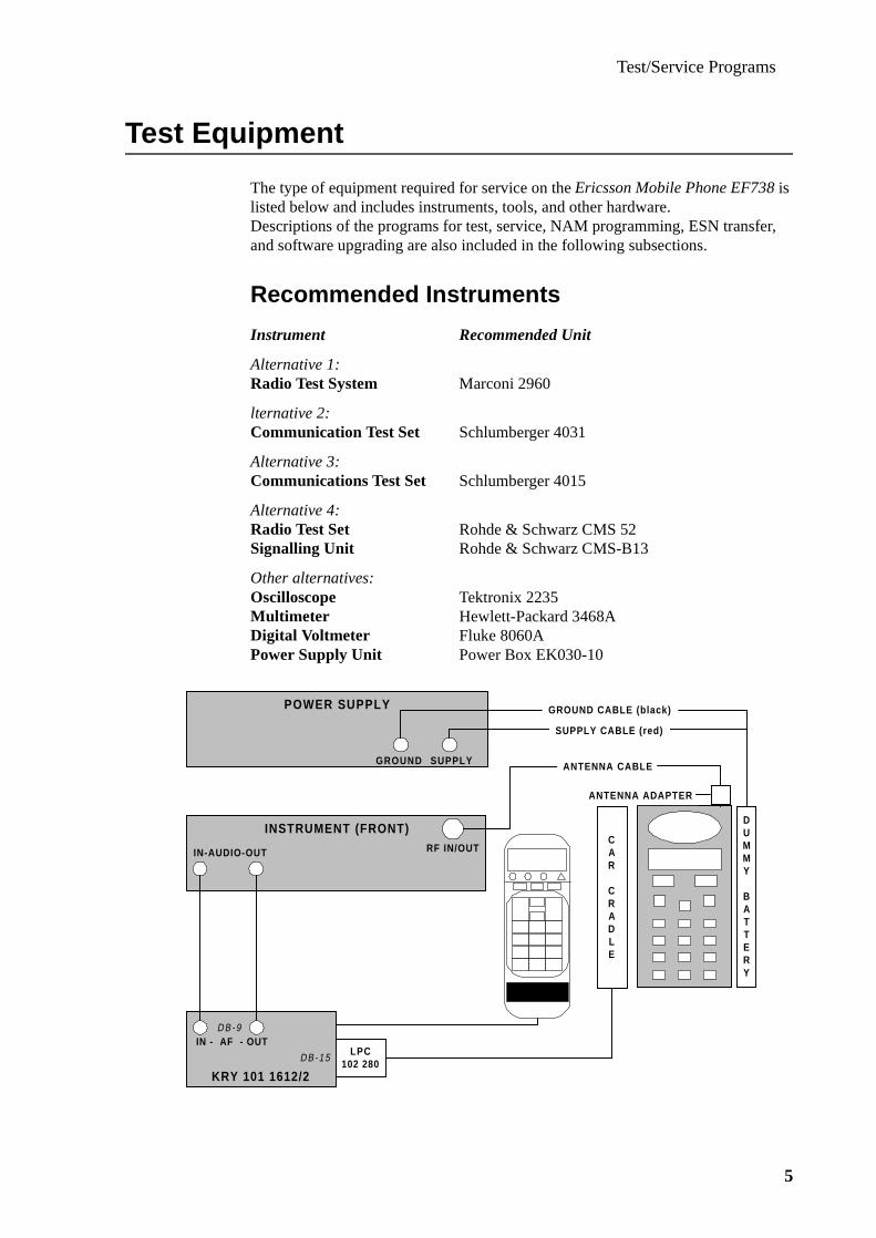
Test/Service Programs
5
Test Equipment
The type of equipment required for service on the Ericsson Mobile Phone EF738 is listed below and includes instruments, tools, and other hardware.Descriptions of the programs for test, service, NAM programming, ESN transfer, and software upgrading are also included in the following subsections.
Recommended Instruments
Instrument Recommended Unit
Alternative 1:Radio Test System Marconi 2960
lternative 2:Communication Test Set Schlumberger 4031
Alternative 3:Communications Test Set Schlumberger 4015
Alternative 4:Radio Test Set Rohde & Schwarz CMS 52Signalling Unit Rohde & Schwarz CMS-B13
Other alternatives:Oscilloscope Tektronix 2235Multimeter Hewlett-Packard 3468A Digital Voltmeter Fluke 8060APower Supply Unit Power Box EK030-10
DUMMY
BATTERY
GROUND SUPPLY
POWER SUPPLY
INSTRUMENT (FRONT)RF IN/OUT
SUPPLY CABLE (red)
GROUND CABLE (black)
ANTENNA CABLE
CAR
CRADLE
IN-AUDIO-OUT
KRY 101 1612/2
IN - AF - OUTDB-9
DB-15LPC
102 280
ANTENNA ADAPTER

Test/Service Programs
6
Other Equipment
Equipment Ordering Number
ETACS Service ProgramProgramming Interface NTZ 112 311Connection Cable KRY 101 1135/10Adapter LPC 102 280Car Cradle KRY 109 1001/72Test Handset NTZ 112 210Antenna Cable NTZ 112 294Antenna Cable Adapter RNT 403 012/003Dummy Battery NTZ 112 310Service Adapter Kit- Test Interface Box LPC 102 280- Audio Box KRY 101 1612/51- Power Supply 110V KRY 101 1612/54- Power Supply 220V KRY 101 1612/55
Standard tools and soldering equipment must also available
Note: When servicing mobile telephones, it is most important that a bench earthing network is used to protect sensitive components against electrostatic discharge (ESD).

Test/Service Programs
7
Test Pro gram
How to Use
This document will describe the use of the built-in test program for the EF738.After the more extensive descriptions found in Individual Test Options, an overview follows in the form of a table with data referring to the different options.This table will become a handy alternative after having some experience of the test program.
Initiating the Test Program
The test program is initiated from the special test handset;by holding down the M button and pressing 90 40 59 orby pressing 90 40 59 followed by M M
However, if the Test Program Enter function is enabled in the telephone, the pro-gram can be initiated and run directly from the keypad by pressing the same sequence (M = MENU ).
When the phone enters the test mode, the hardware becomes initialized and the text TEST INPUT appears in the display.
To step forward and backwards in the test program; press SEND and RCL.To choose a specific test; press its number followed by the # button.
Return to TEST INPUT
Press the C or M button to return to the input mode where the TEST INPUT prompt is displayed.
Exit
To exit from the test program; select test option 99 and press the # button.

Test/Service Programs
8
Individual Test Options
A list describing the use of the test program options follows below.A summary of the test options and possible parameter values is given as well.
1 CH NUMBER Setting of channel numberChoose any chanel in the ETACS system (0-600, 1329-2047). Default setting is channel 1.To change channel number; enter a 4-digit decimal number fol-lowed by #.Use * and # to step backwards/forwards.Channel number and signal strength are displayed.
2 TX POWER Sets the transmitter on and offF and determines the output power level.8 off 7 power level 7; minimum output power6 power level 65 power level 54 power level 43 power level 32 power level 2; maximum output powerWhen the power reduction function is activated in menu 76, power level 2 will be displayed as ‘S’.When the extra power option in menu 76 is activated,power level 2 will be displayed as ‘X’.
4 FLASHER Used only when loading the program into a terminal.
5 PWR CAL Calibration of power levels. Transmitter is turned on and tuned to the calibration channel.Modify the power levels with the following keys:# / * increases/decreases the power levelM+S stores the value and steps to next power level;
transmitter is turned onM+# starts calibration and displays power level;
steps forward to next power level (2->3->...->7->2).C turns off TX, restores channel no., returns to menu 0.
6 TX DETECT Performs two simple transmitter tests: a general Go/NoGo trans-mitter test and a transmitter leakage test.To start the test, press any key except C.The result is displayed when the test is finished:FF both tests passed01 general transmitter test failed02 leakage test failed
7 TX SENS Factory and level 5 repair only

Test/Service Programs
9
9 RF CAL Calibrates the RSSI levels based on the level of the signal cur-rently being received.The value determined for each level is the minimum strength signal for that level, averaged over 16 readings to provide a more reliable value.The value for level 0 is used to update the Receiver Carrier Detect (RXCD) such that signals below this level are ignored.This value (plus a fixed offset) also determines the minimum signal threshold for the AFC.When the received signal is below this threshold, the AFC pro-vides TCXO compensation based on a default temperature com-pensation table.The values for level 1 and 5 are used to determine the RSSI graph to display.The values for level 2, 3 and 4 are interpolated from these two reference levels.M+# displays the next RSSI level number and its current valueM+S reads an averaged RSSI value and stores it
10 RX SENS Adjustment of the receiver audio outputM+# enables calibration and echoes the initial value# / * increases/decreases the value by 1; new value is echoedM+S stores the current value
11 KEYPAD Factory and level 5 repair only
13 BANDGAP Factory and level 5 repair only
14 AUDIO DEV Adjustment of the audio deviationM+# enables calibration and echoes the initial value# / * increases/decreases the value by 1; new value is echoedM+S stores the current value
15 AFC Sets the AFC operating mode and displays AFC information0 only temperatue compensation1 temp. + age compensation2 temp. + age + freq. compensation, smoothed (default)3 temp. + age + freq. compensation, no smooth4 no compensationAny other code entered in handset mode will display:ABCCDDEEFF whereA = AFC operating mode 0 only temperatue compensation 1 temp. + age compensation 2 temp. + age + freq. compensation, smoothed (default) 3 temp. + age + freq. compensation, no smooth 4 no compensation

Test/Service Programs
10
B = AFC state 1 waiting for signal; (no valid RSSI, compensate for temp. or temp. + age) 2 acquiring lock;
(RSSI good, use whole freq. error for 1.5 sec for fast lock) 3 locked (RSSI good, use smoothed freq. compensation) 4 freeze lock ( RSSI temporarily lost, compensate for
temp + age + (frozen) freq. error for up to 30 sec.) 5 locked using short count;
(RSSI good, use smoothed freqcompensation);only entered when current savings is active;short freq. measurements is used to find freq. error com-pensation
6 entered when DRX has started;compensate for temp. + age + (frozen) freq. error.
CC total compensationDD temperature table componentEE age componentFF frequency error component
18 DAC2CAL Calibration of the VCTCXO.M+# enables calibration and echoes the initial value# / * increases/decreases the value by 1; new value is echoedM+S stores the current valueDuring the calibration the AFC is in ‘Temperature only compen-sation mode’ (Tp-15:0)Upon exiting the calibration the AFC returns to its previously selected operating mode.
19 RX SAT Factory and level 5 repair only
20 AUDIO Sets the audio paths in the audio circuitKey TX-audio RX-audio0 muted muted1 unmuted muted2 muted unmuted3 unmuted unmuted
21 HANDSET Sets the audio paths in the handset.0 microphone off, earphone off, loudspeaker off (default)1 microphone on, earphone on, loudspeaker off 2 microphone off, earphone off, loudspeaker on
22 TX SAT Controls the SAT tone switch and TX SAT deviation.0 generate 5970 Hz SAT1 generate 6000 Hz SAT2 generate 6030 Hz SAT3 no SAT generated4 SAT tone switch setting = ON5 SAT tone switch setting = OFFM+# enables calibration and echoes the initial value# / * increases/decreases the value by 1; new value is echoedM+S stores the value

Test/Service Programs
11
23 MANCH OUT Controls the wideband data and deviationTo transmit these data the transmitter must be switched on. 0 off - no data output)1 8kHz output; ones 2 8kHz output; zeros 3 hardcoded idle frame; 0101010101M+# enables calibration and echoes the initial value# / * increases/decreases the value by 1; new value is echoedM+S stores the value
24 MANCH IN Displays the latest received data from the base station.The value is displayed each time a key is pressed.
25 VOLUME Sets the earpiece and loudspeaker volume.Possible values: 0 - 7 (default: 3)
26 DTMF DTMF tones consist of a lower frequency in combination with a higher frequency.The test enables listening to either or both as follows:0 low frequency1 high frequency2 both frequencies.# / * scroll forwards/backwards to next/previous DTMF toneM+# enables calibration and echoes the initial value# / * increase/decrease the value by 1; new value is echoedM+S stores the value
27 TX SOURCE Sets the TX audio paths in the audio circuit.Also possible to adjust the levels of the different audio paths.0 external line input, ATMS (default)1 internal MIC2 internal MIC with MicAmp gainM+# enables calibration and echoes the initial value# / * increases/decreases the value by 1; new value is echoedM+S stores the value
28 EARPIECE Sets the earpiece mute switch in the audio circuit to allow for adjustment of the earpiece sensitivity values.
0 internal earpiece disconnected1 internal earpiece connected2 audio sent out AFMS on system connector (default)
internal earpiece and AFMS can both be adjustedM+# enables calibration and echoes the initial value# / * increases/decreases the value by 1; new value is echoedM+S stores the value
29 COMP Selects compander or linear modeM+# displays the current compander settingsM+0 linear mode (default)M+1 companding mode

Test/Service Programs
12
30 HF Controls the handsfree attenuation level for RX and TX audioM+0 selects RX handsfree audio gain settings
and echoes initial gain settingsM+1 selects TX handsfree audio gain settings
and echoes initial gain settings0-7 sets the gain for the selected path:
0=0dB, 1=-7dB, 2= -14dB, ... 7=-49dB
32 SOFTLIMIT Sets the use of the softlimiter in the audio circuit.Changes made are temporary and will not update the EEPROM.
35 COUNTRY Factory and level 5 repair only
36 BER Factory and level 5 repair only
37 OMC Factory and level 5 repair only
38 ADC Displays the different hex values from the ADCM+1 RSSIM+2 battery voltageM+3 unusedM+4 temperature senseM+5 bandgap referenceM+6 current senseM+7 handsfree level
39 DAC Changes temporarily the output voltage from the DAC.M+1 normally controlled by AFCM+2 normally trimmed using ‘MENU 18’M+3 power levelxxx M+#decimal value followed by ‘MENU + #’ sent directly
to the active DAC (valid values: 000 - 255)# / * increases/decreases value by 1; new value is echoed
40 INPORT Shows the status of the different inports (updated every second)M+1 external audio connection detected
0 = input high1 = input low
M+2 state of CPU port 2M+3 flip status
0 = flip closed1 = flip open
M+4 transmitter status0 = transmitter off1 = transmitter on
M+6 external handsfree detected0 = input low1 = input high
M+7 receiver carrier detect0 = RSSI < sensitivity limit1 = RSSI > sensitivity limit
# immediately reads the selected port

Test/Service Programs
13
41 OUTPORTS Shows the status of the selected outportFirst select a digital outport:M+1+0 VRXM+1+1 VTX, Note! VRX must be on!M+1+2 power down VCOM+1+3 unusedM+1+4 SWDCM+1+5 MPD2M+1+6 FMPD1M+1+7 unusedM+1+8 temperatureM+2 ICTRLM+3 MUTEM+4 green LEDM+5 red LEDM+6 back lightThen select the state:0 set output low1 set output high
42 DSCR Turns the discriminator and multiplier on and off0 discriminator off1 discriminator on (default)
43 BAR Tests the different tones of the phone0 continous ringing signal at maximum volume1 continuos alarm signal2 click signal single pulse3 error signal single pulse4 continuous 3kHz ringing tone
45 LCD Tests the different segment and icons of the display as five dif-ferent patternsM+digit (1-5) shows the selected pattern no. (1-5)# shows all patterns continuously
starting with pattern no. 1C or S terminates the test
46 PWR DOWN Factory and level 5 repair only
47 SW REV Displays the software, revision and ESN inside the terminal.Press any key to show software name and revision.Additional pressure of any key will show the ESN.
48 SYNTH Factory and level 5 repair only
49 RX PWR Factory and level 5 repair onlyMODE
50 GUARANTEEPress any key to display year and month when warranty/guaran-tee was activated and the length (months)of the warranty period
53 SYNT I SET Factory and level 5 repair only
54 EEPROM Factory and level 5 repair onlyINIT
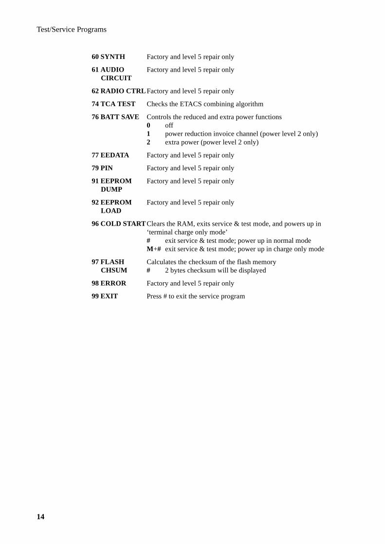
Test/Service Programs
14
60 SYNTH Factory and level 5 repair only
61 AUDIO Factory and level 5 repair onlyCIRCUIT
62 RADIO CTRL Factory and level 5 repair only
74 TCA TEST Checks the ETACS combining algorithm
76 BATT SAVE Controls the reduced and extra power functions0 off1 power reduction invoice channel (power level 2 only)2 extra power (power level 2 only)
77 EEDATA Factory and level 5 repair only
79 PIN Factory and level 5 repair only
91 EEPROM Factory and level 5 repair onlyDUMP
92 EEPROM Factory and level 5 repair onlyLOAD
96 COLD STARTClears the RAM, exits service & test mode, and powers up in ‘terminal charge only mode’# exit service & test mode; power up in normal modeM+# exit service & test mode; power up in charge only mode
97 FLASH Calculates the checksum of the flash memoryCHSUM # 2 bytes checksum will be displayed
98 ERROR Factory and level 5 repair only
99 EXIT Press # to exit the service program

Test/Service Programs
15
Overview of the Test Program
Menu Possible Values
1 CH NUMBER 0-600, 1329-2047
2 TX POWER 8 (off) - 2 (maximum power)
4 FLASHER only used when loading program into terminal
5 PWR CAL calibration of power levels
6 TX DETECT simple test of transmitter
7 TX SENS factory and level 5 repair only
9 RF CAL RSSI calibration
10 RX SENSE adjustment of receiver audio output
11 KEYPAD factory and level 5 repair only
13 BANDGAP factory and level 5 repair only
14 AUDIO DEV adjustment of maximum audio deviation
15 AFC sets AFC operating mode and displays AFC information
18 DAC2CAL calibration of VCTCXO
19 RX SAT factory and level 5 repair only
20 AUDIO sets audio paths in audio circuits
21 HANDSET sets audio paths in handset
22 TX SAT controls SAT tone switch and TX SAT deviation
23 MANCH OUT controls wideband data and deviation
24 MANCH IN displays latest received data from base station
25 VOLUME sets earpiece and loudspeaker volume
26 DTMF DTMF tones
27 TX SOURCE sets TX audio paths in audio circuit
28 EARPIECE sets earpiece mute switch in audio circuit
29 COMPAND selects compander/linear mode
30 HF controls handsfree attenuation level for RX and TX audio
32 SOFTLIMIT sets use of softlimiter in audio circuit
35 COUNTRY factory and level 5 repair only
36 BER factory and level 5 repair only
37 OMC factory and level 5 repair only
38 ADC displays different hex values from ADC
39 DAC changes temporarily output voltage from DAC
40 INPORTS shows status of different inports

Test/Service Programs
16
Menu Possible Values
41 OUTPORTS selects status of selected outport
42 DISCR turns discriminator/multiplier on/off
43 BAR tests different tones of phone
45 LCD tests different segments and icons of display
46 PWR DOWN factory and level 5 repair only
47 SW REV displays software, revision and ESN inside terminal
48 SYNTH factory and level 5 repair only
49 RX PWR MODE factory and level 5 repair only
50 GUARANTEE warranty information
53 SYNT I SET factory and level 5 repair only
54 EEPROM INIT factory and level 5 repair only
60 SYNTH factory and level 5 repair only
61 AUDIO CIRCUIT factory and level 5 repair only
62 RADIO CTRL factory and level 5 repair only
74 TCA TEST checks ETACS combining algorithm
76 BATT SAVE controls reduced and extra power functions
77 EEDATA factory and level 5 repair only
79 PIN factory and level 5 repair only
91 EEPROM DUMP factory and level 5 repair only
92 EEPROM LOAD factory and level 5 repair only
96 COLD START powers up in ‘terminal charge only mode’
97 FLASH CHSUM calculates checksum of flash memory
98 ERROR factory and level 5 repair only
99 EXIT press # to exit service program
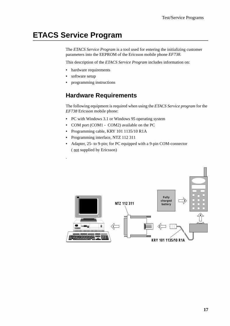
Test/Service Programs
17
ETACS Service Pro gram
The ETACS Service Program is a tool used for entering the initializing customer parameters into the EEPROM of the Ericsson mobile phone EF738.
This description of the ETACS Service Program includes information on:
• hardware requirements
• software setup
• programming instructions
Hardware Requirements
The following equipment is required when using the ETACS Service program for the EF738 Ericsson mobile phone:
• PC with Windows 3.1 or Windows 95 operating system
• COM port (COM1 - COM2) available on the PC
• Programming cable, KRY 101 1135/10 R1A
• Programming interface, NTZ 112 311
• Adapter, 25- to 9-pin; for PC equipped with a 9-pin COM-connector
( not supplied by Ericsson)
.
KRY 101 1135/10 R1A
NTZ 112 311
2
4
1
3Fully
chargedbattery

Test/Service Programs
18
Software Installation
The ETACS Service Program consists of four files:
• SPEP1361.EXE• TYPE1361.CFG• TYPE1361.EDT• TYPE1361.MNU
The program can be run directly from a diskette, but it is adviseable to have it run from the hard disk.Simply install the software on the hard disk by copying the contents of the diskette to a suitable directory on the hard disk.
The copying of files mentioned above describes how to install the ETACS Service Program from a standard floppy disk, but the program may become distributed in other media formats.
CAUTION!Use a fully charged phone battery, since the interface is powered by the phone. Using an even slightly discharged battery may result in misreadings, even if the Low Battery warning has not yet appeared.
Starting the Program
Turn the phone On.Start the program by double-clicking the file SPEP1361.EXE in the File Manager / Explorer, and the following picture appears on the screen:
Select the serial port (COM1 or COM2) where the programming interface is con-nected, as instructed on the screen.
Press digit 1 to use COM1:
Press digit 2 to use COM2:
Press ESC to continue.
1
2
Esc
SELECT COM PORT
File Edit Short Numbers Options

Test/Service Programs
19
The Programming Cycle
Details of the different entries are given in ‘Using the Menus’.Below is a brief description of the main events.
After selection of the COM port the Subscriber Data editing window is automati-cally displayed. Most customers will require data to be entered in this window only. Move the cursor by the arrow keys of the PC, or click the mouse on the respective field of the window.Press the Esc key to return to the main menu on the top row of the screen.
The service program will fetch ‘today’s date’ from the system clock of the PC.Check and (if necessary) correct the date before starting the programming.
When ready to program the telephone, i.e. transfer data into the EEPROM:
• Press F2 while keeping the ALT -key depressed (ALT+F2 )
• Confirm by pressing the Y-key
After the programming the result can be verified by pressing ALT+F3 .
To exit the program, press ALT +X.
Using the Menus
How to Select
Press Esc to reach the menu.From a 'Data edit window' it is also possible to go directly to a sub-menu by holding down the ALT key and pressing the highlighted letter in the main menu, e.g. ALT+F to go to File functions.
Move the selection bar (reverse video) to the left or right by the keypad arrow keys to select a sub-menu and press Enter to open it. The functions in the sub-menu are selected by moving the selection bar up or down using the arrow keys.Press Enter to activate the selected function, or Esc to return to the main menu.
Sub-menus and functions can also be reached by clicking with the mouse.
Subscriber No. part1Subscriber No. part2Mobile Stat. Id. No.ACCOLCHome Traffic AIDGuarantee Start,mmyyGuarantee Length,mmLock Code
0836123456123456508031097120000
SUBSCRIBER DATA

Test/Service Programs
20
The Functions
NOTE! Defaults are printed in italic.
File
The ‘File’ sub-menu includes the functions listed below:
Read Transfers the contents of the EEPROM to the computer memory.CAUTION! When using this function, make sure to reload the configuration file before programming other phones, as incor-rect data inadvertently might be programmed.
Burn Programs the phone with the Subscriber, Country and System data that has been entered into the PC memory.
Verify Comparison between the PC memory and the phone.
Save This command has two different functions:
1. Creates a configuration file which is automatically loaded ateach program start.The file name must be manually changed to TYPE1361.CNF.All data from the edit windows are saved.Guarantee Start is set to ‘today's date’ by the system clock.
2. Saves the data in the phone before service.Data in the edit windows is saved if the file name is otherthan TYPE1361.CNF.Default name is STATION1.SAV.
Load Reloads a configuration file.
Reset PIN Resets the PIN to 0000.
Activate DRX Activates the Discontinuous Reception feature.CAUTION! May deteriorate the performance of the phone,if DRX is not supported by the system
Deactivate DRX Deactivates the Discontinuous Reception feature.
Exit Quit the program.
ReadBurnVerifySaveLoadReset PINActivate DRXDeactiv. DRXEXit
Alt F1Alt F2Alt F3Alt F5Alt F6Alt F7Alt F8Alt F9Alt X
File

Test/Service Programs
21
Edit
When leaving the ‘File’ menu the ‘Subscriber Data’ edit window is displayed.After pressing Esc the ‘Edit’ sub-menu is reached and the editing windows listed below can be accessed:
SUBSCRIBER DATA
Subscriber No. Part 1/Part 2The Subscriber No. (shown in certain menues and at power on) is information intended for the user and is not used by the system.
Mobile Station Identification No.The 6 least significant digits of the international mobile station number,usually identical to the 6 least significant digits of the subscriber number.
ACCOLCThe Access Overload Class is normally the second last digit of the Mobile Station Identification No.
Home Traffic AIDThe Home Traffic Area Identification is entered as a hexadecimal code.
Guarantee Start, mmyyIs read from the PC's system clock at program start, but can be manually altered.
Guarantee Length, mmTo be used in conjunction with the Guarantee Start.
Lock CodeThe subscriber's four-digit lock code which must initially be set to 0000 to comply with the information of the User's Manual.
Subscriber DataMisc MMI FeaturesSounds & GeneralCall Set & CallDataSystem & ServicesSys Opt & Restrict.LanguagesNAM & Quick NAMCountry data 1
Edit
Country data 2Country data 3Country data 4
Subscriber No. part1Subscriber No. part2Mobile Stat. Id. No.ACCOLCHome Traffic AIDGuarantee Start,mmyyGuarantee Length,mmLock Code
0836123456123456508031097120000
SUBSCRIBER DATA

Test/Service Programs
22
MISCELLANEOUS MMI FEATURES
Roaming Indicator TypeY = Icon flashingN = Icon steady on
Auto RetryY = Enables Automatic Retry when network is busyN = Disables Automatic Retry when network is busy
Call Count FeatureY = Enables registration of unanswered incoming callsN = Disables registration of unanswered incoming calls
Arrow Indication 0: no arrow is displayed1: one arrow is displayed2: one arrow followed by hyphen is displayed
Left Arrow SegmentsLayout of Left Arrow Segments: 22C0HEX, (not to be changed)
Right Arrow SegmentsLayout of Right Arrow Segments: 0251HEX, (not to be changed)
International Lock DigitsNo. of digits as hex. code to define the minimum length of an international phone number
Three Level MenuY = 3-level user menu structure is set to comply with the User’s ManualN = 2-level user menu structure
Roam. indicat. typeAuto RetryCall Count FeatureArrow IndicationLeft Arrow SegmentsRight Arrow SegmentsInt. lock digitsThree level menu
NYY122C002510AY
MISC MMI FEATURES

Test/Service Programs
23
SOUNDS & GENERAL
Ring Volume Menu Y = Ringing volume selection ‘Low/Med/High/Step/Silent’ enabledN = Ringing volume selection disabled.
RingTone MenuY = Ringing tone selection ‘Low/Med/High/Mixed/Scale/Fast/Melodies’ enabledN = Ringing tone selection disabled.
KeySound MenuY = Key sound selection ‘Burst/Continuous/Click/Silent’ enabledN = Key sound selection disabled
Silent MenuY = Silent Mode selection ‘Off/On’ enabledN = Silent Mode selection disabled
BackLite MenuY = Backlight selection ‘Off/On 10sec/On 20sec’ enabledN = Backlight selection disabled
Greeting MenuY = Greeting String (at power on) choice enabledN = Greeting String disabled
Language MenuY = Language selection ‘English/Espanol/Italiano/Deutsch/Melayu’ enabledN = Language selection disabled
Reset MenuY = Reset option ‘Reset All’ enabledN = Reset option disabled
Memory Used MenuY = Memory Used Menu is accessableN = Memory Used Menu not accessible
KeyLock MenuY = Key lock selection ‘Unlock/Lock’ enabledN = Key lock selection disabled
Ring Vol MenuRingtone MenuKeysound MenuSilent MenuNot used, set to NBacklite MenuGreeting Menu
YYYYN N NYY
SOUNDS & GENERAL
Language MenuReset MenuMem Used MenuKeylock MenuNot used, set to N N N
YYYY

Test/Service Programs
24
CALL SET & CALL DATA
FastDial MenuY = Fast Dial (one-key-dial) selection ‘Off/On’ enabledN = Fast Dial selection disabled
Flip MenuY = Flip (answer/end-call) selection ‘Off/On’ enabledN = Flip answer/end-call disabled
Answering Option MenuY = Answering method selection ‘Any Key/Send Only’ enabledN = Answering method selection disabled
Minder MenuY = Minder (minute beep) selection ‘Off/On’ enabledN = Minder selection disabled
Tone Send MenuY = Tone Send (DTMF when key pressed during call) selection ‘Off/On’ enabled N = Tone Send selection disabled
Access Tone MenuY = Access Tone (outgoing call established) selection ‘Off/On’ enabled N = Access Tone selection disabled
Air Info MenuY= Air Info (duration or charge) display selection ‘Air Time/Call Charge’ enabledN = Air Info disabled
Call Type MenuY = Call Type charge (out or out/in) display selection ‘Only Out/Out and In’enabledN = Call Type charge display selection disabled
Last Time MenuY = Last Time (duration of last call) display selection enabledN = Last Time display selection disabled
Last Charge MenuY = Last Charge (no. of charge units for last call) display selection enabledN = Last Charge display selection disabled
Total Time MenuY = Total Time (since counter reset) display selection enabledN = Total Time display selection disabled
Fastdial MenuFlip MenuAnsw Opt MenuMinder MenuTonesend MenuAcc Tone MenuAir Info MenuCall Type Menu
YYYYYY
Y
CALL SET & CALLDATA
LastTime MenuLastChar MenuTot Time MenuTot Char MenuCall Cnt Menu
N
YNYNY
Not used, set to N N N N

Test/Service Programs
25
Total Charge MenuY = Total Charge (since counter reset) display selection enabledN = Total Charge display selection disabled
Call Count MenuY = Call Count (no. of in/out-going calls since reset) display selection enabledN = Call Count display selection disabled

Test/Service Programs
26
SYSTEM & SERVICES
ETACS TypeY = Phone is an ETACS typeN = Phone is a TACS only type
ITACS TypeY = Phone is an ITACS typeN = Used in combination with ETACS type
Mobile Station supported TACS level0: if TACS1: if TACS-2
Calling Line IdentificationY = Calling Line Identification functions enabledN = Calling Line Identification functions disabled
Long NAM Programming EntryY = User access to the NAM menu is enabledN = User access to the NAM menu is disabled
Test Program EntryY = The test program is accessed by entering a code on the keypadN = The test program cannot be accessed from the keypad
Country Menu EntryY = User access to the Country Menu is enabledN = User access to the Country Menu is disabled
Rescan Time, minutesNo. of minutes until a Rescan is started (default: 5 minutes) after signalling
Handset FeatureY = Handset Feature enabledN = Handset Feature disabled
No. of Auto RetriesMax. number of Automatic Retries (default: 3)
System Busy Wait TimeTime between attempts in Auto Retry when system is busy (default: 0AHEX)
Called Side Busy Wait TimeTime between attempts in Auto Retry when called number is busy (default: 1EHEX)
ETACS TypeITACS TypeMS supp. TACS levelCall Line Identific.Long NAM Prog. EntryTest Program EntryCountry Menu EntryRescan Time, minutes
YN1YNN
5
SYSTEM & SERVICES
Handset FeatureNo of Auto RetriesSys. Busy Wait TimeCalled side BW TimeKeypad Layout Type
Y
N30A1E1
ABC Indicator Debug 0Not used, set to 00 00

Test/Service Programs
27
Keypad Layout Type0: Not applicable1: New international alpha keypad layout
ABC Indicator DebugEnables the use of special indicators, ‘ABC’, for internal tests:0: not used1: NAM system indication2: Accessory indication3: Data/Voice mode4: TX power indication5: Power save indication
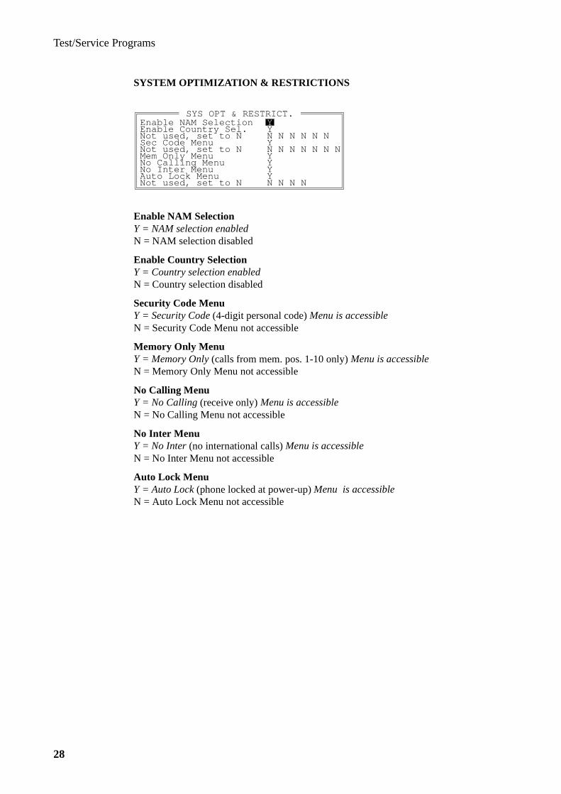
Test/Service Programs
28
SYSTEM OPTIMIZATION & RESTRICTIONS
Enable NAM SelectionY = NAM selection enabledN = NAM selection disabled
Enable Country SelectionY = Country selection enabledN = Country selection disabled
Security Code MenuY = Security Code (4-digit personal code) Menu is accessibleN = Security Code Menu not accessible
Memory Only MenuY = Memory Only (calls from mem. pos. 1-10 only) Menu is accessibleN = Memory Only Menu not accessible
No Calling MenuY = No Calling (receive only) Menu is accessibleN = No Calling Menu not accessible
No Inter MenuY = No Inter (no international calls) Menu is accessibleN = No Inter Menu not accessible
Auto Lock MenuY = Auto Lock (phone locked at power-up) Menu is accessibleN = Auto Lock Menu not accessible
Enable NAM SelectionEnable Country Sel.Not used, set to NSec Code MenuNot used, set to NMem Only MenuNo Calling MenuNo Inter Menu
YYN N N N N NYN N N N N N NY
Y
SYS OPT & RESTRICT.
Auto Lock MenuNot used, set to N
Y
YN N N N

Test/Service Programs
29
LANGUAGES
SpanishY = Spanish language selectableN = Spanish language not selectable
ItalianY = Italian language selectableN = Italian language not selectable
DeutschY = German language selectableN = German language not selectable
MelayuY = Malayan language selectableN = Malayan language not selectable
NAM & QUICK NAM
The table above displays the various programmable parameters for:
• NAM programming (center column)
• Quick NAM programming (right column)
By entering a Y, the parameter becomes accessible for programming.By entering a N, the parameter becomes not accessible for programming.
The default settings for the accessibility of the NAM and Quick NAM parameters are as listed in the table above.
For more detailed information, refer to ‘Keypad NAM Programming’ which is found further on in this section.
Not used, set to YSpanishItalianDeutschMelayu
YYYYYN N N
LANGUAGES
Not used, set to N
ESNCODEROAM TYPECHARGECHAN, FCCHA, FCCHBBANDA, BANDBNO EMERGEMERG 1, EM.2, EM.3
Y Y
YYY Y YY Y
Y Y Y
NAM & QUICK NAM
ENQUIRYINTER PREFNAMIMSI, SUBNSYSTEM
Y
YYYY YY
AIDH, FPCH, ROAM Y Y YACCOLC, LOCAL, EXT Y Y YNot used, set to Y/N Y Y Y Y Y Y Y N N N N N N N
N N NY N N
Y Y
N N N
N NN N N
Y NNY
N
N
NY
N
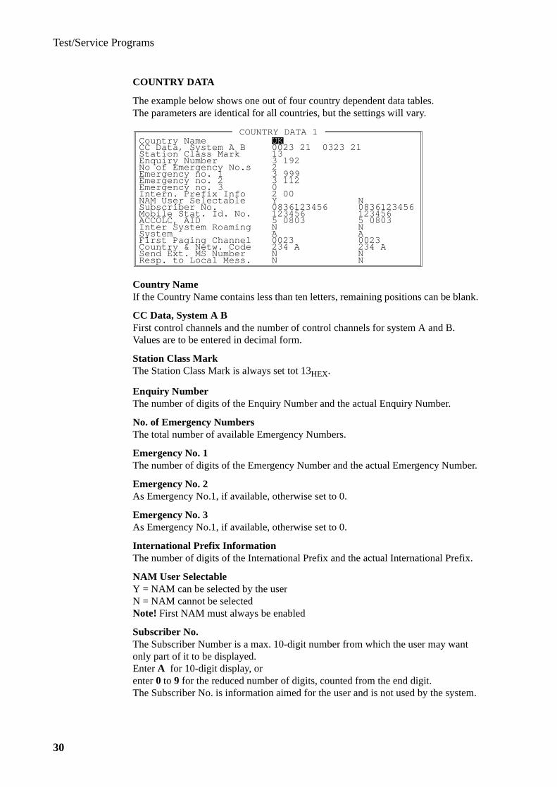
Test/Service Programs
30
COUNTRY DATA
The example below shows one out of four country dependent data tables.The parameters are identical for all countries, but the settings will vary.
Country NameIf the Country Name contains less than ten letters, remaining positions can be blank.
CC Data, System A BFirst control channels and the number of control channels for system A and B.Values are to be entered in decimal form.
Station Class MarkThe Station Class Mark is always set tot 13HEX.
Enquiry NumberThe number of digits of the Enquiry Number and the actual Enquiry Number.
No. of Emergency NumbersThe total number of available Emergency Numbers.
Emergency No. 1The number of digits of the Emergency Number and the actual Emergency Number.
Emergency No. 2As Emergency No.1, if available, otherwise set to 0.
Emergency No. 3As Emergency No.1, if available, otherwise set to 0.
International Prefix InformationThe number of digits of the International Prefix and the actual International Prefix.
NAM User SelectableY = NAM can be selected by the userN = NAM cannot be selectedNote! First NAM must always be enabled
Subscriber No.The Subscriber Number is a max. 10-digit number from which the user may want only part of it to be displayed.Enter A for 10-digit display, orenter 0 to 9 for the reduced number of digits, counted from the end digit.The Subscriber No. is information aimed for the user and is not used by the system.
Country NameCC Data, System A BStation Class MarkEnquiry NumberNo of Emergency No.sEmergency no. 1Emergency no. 2Emergency no. 3
UK
133 19223 999
0
COUNTRY DATA 1
Intern. Prefix InfoNAM User SelectableSubscriber No.Mobile Stat. Id. No.ACCOLC, AID
3 112
2 00Y08361234561234565 0803
Inter System Roaming NSystem AFirst Paging Channel 0023
0023 21 0323 21
N
Country & Netw. CodeSend Ext. MS NumberResp. to Local Mess.
234 ANN
NN
234 A
08361234561234565 0803NA0023

Test/Service Programs
31
Mobile Station Identification No.The 6 least significant digits of the international mobile station number,in most countries equal to the 6 least significant digits of the subscriber number.
ACCOLC, AIDThe Access Overload Class, normally the last digit of the Mobile Station Id. No., followed by the Home Traffic Area Identification entered as hex. code.
Inter System RoamingY = Inter System Roaming enabledN = Inter System Roaming disabled
SystemA = System A is the home system in the NAMB = System B is the home system in the NAM
First Paging ChannelFirst paging channel in the present NAM to be entered in decimal form.
Country & Network CodeMobile Country Code (3 digits), followed by Mobile Network Code (1 digit), for the present NAM.
Send External Mobile Station NumberY = Phone must send the extended address word when accessing the systemN = Extended address word not required when accessing the system
Response to Local MessageY = Phone must respond to local control messages sent on the FOCCN = Response not required to local control messages sent on the FOCC
Short Numbers
Save To Disk Reads the short numbers from the telephone andtransfers them to a file, see below.
Load From Disk Reads short numbers from a file and stores (burns)them in the phone.
Clear Mobile Clear all short numbers in the phone.
Options
COM Port Possible to change the COM-port whithout leaving theprogram, for example, when having programming interfacesconnected to both COM-ports.
Save To DiskLoad From DiskClear Mobile
Short Numbers
Com Port
Options
Test/Service Programs
32
Re-Programming a Telephone
When making changes to a telephone that has already been programmed,first read the EEPROM by pressing ALT+F1 .Then perform the desired changes and program the EEPROM by pressing ALT+F2 . Verify by pressing ALT+F3 .
Note: Make sure that the configuration file has been reloaded before programming other phones. Otherwise incorrect data may inadvertently be programmed.
Contents of Saved Short Number Files
The ‘Save’ file is a normal text file which may be edited by any word processor or text editor as an ASCII text file. It is possible to create a file independently from the program, and then use the program for transfer to the telephone. The file does not have to list the short numbers in any particular order, and it is not necessary to sup-ply all 99 numbers.
For example, it is possible to create a file with only three short numbers at pos. 21, 22, and 23, and add these to a phone that already has some numbers programmed.
Each line of the file should have the following form:
1. Two digits representing the Short Number positions from 01 through 99.
2. Name of the subscriber, maximum 10 characters, letters and digits.
3. Telephone number of no more than 16 or 32 characters (system dependent).Digits 0 - 9, * , and # are allowed.
Example:
01 ERICSSON 009464619300002 JOHN DOE 1234567803 TRANSFER *21*9171234567#
Lines containing the positions only will erase the shortcodes, for example:040506
A line containing text only ‘NO NUMBERS’ is a comment and will not cause any programming of the telephone.

Test/Service Programs
33
Keypad NAM Pro grammin g
The Keypad NAM (Number Assignment Modules) Programming includes not only the NAM parameters but also some functionally related parameters as well as coun-try dependent parameters.
Two different Keypad NAM Programming modes are available:
• Long NAM (non-user selectable by default)
• Quick NAM (always selectable)
A list of the available programmable parameters, programming instructions, and country-related default values for Long resp. Quick NAM follows.

Test/Service Programs
34
Long NAM Programming
Programmable Parameters
Electrical Serial Number (ESN)The ESN, which is a unique binary number that identifies the MS to the cellular sys-tem, is set by the factory and can not be modified.
Security CodeThis code gives the user access to protected memory locations, resetting of menus, and setting of call restrictions.
Roam TypeThe roaming indicator can be set in three different modes: off, flashing, steady-on.
Subscription with Charge RateThis parameter determines whether AirTime/CallCharge is selectable by the user.
Number of ChannelsDefines the allowed number of channels according to the frequency band.
First Dedicated Control Channel in System AThis control channel number can be programmed in service mode for internal tests.
First Dedicated Control Channel in System BThis control channel number can be programmed in service mode for internal tests.
Total Number of Dedicated Control Channels in System AMaximum number of dedicated control channels in System A.
Total Number of Dedicated Control Channels in System BMaximum number of dedicated control channels in System B.
Number of Emergency NumbersDetermines the number (≤3) of available emergency numbers for the country.
Emergency Number 1States the first emergency number.
Emergency Number 2States the second emergency number (if exists).
Emergency Number 3States the third emergency number (if exists).
Enquiry NumberStates the enquiry number
Country International PrefixPrefix required when dialing an international call.This parameter detects an international call at call restrictions.

Test/Service Programs
35
NAMEach country area is subdivided into NAM-areas NAM1 and NAM2, which are pro-grammed with System A and System B parameters when shipped from factory.A configuration of system and subscriber data (preferred system, subscriber number, etc.) can be programmed into each NAM.
International Mobile Station Identity (IMSI)This IMSI identity is a 10-digit number composed of three parts:- MNC (Mobile Network Code), 3 digits- MCC (Mobile Country Code), 1 digit- MSIN (Mobile Station Identification Number), 6 digits
Subscriber NumberThe subscriber number may include from 0 up to 10 digits.
Pref SysBoth NAMs associated with each country are programmable to become operable in both systems. If both systems are programmed as System A, the automatic NAM switch function will search the A system channels for both NAMs.
Home System Identity Number (AID)This identity number states the subscriber home system and is provided by the sub-scription operator.
First Paging ChannelThe first paging channel is programmed in service mode and the appropriate value for this parameter is provided by the home system operator at subscription.
RoamThis parameter defines whether inter system roaming is allowed on the comple-menting network or not. If set, it will enable the use of both systems (A and B) in the present NAM.
Access Overload ClassOverload class field that controls access attempts made by the MS (identical to the second last digit of the IMSI).
Response to Local Control Message EnabledDetermines whether the MS will respond to Local Control Messages sent on the Forward Control Channel.
Sending of Extended MS NumberDetermines whether the MS must send the extended address word when accessing the system.
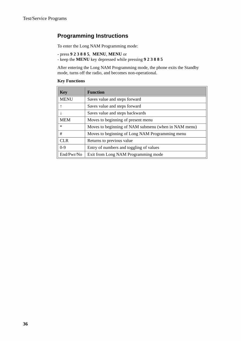
Test/Service Programs
36
Programming Instructions
To enter the Long NAM Programming mode:
- press 9 2 3 8 8 5, MENU , MENU or- keep the MENU key depressed while pressing 9 2 3 8 8 5
After entering the Long NAM Programming mode, the phone exits the Standby mode, turns off the radio, and becomes non-operational.
Key Functions
Key Function
MENU Saves value and steps forward
↑ Saves value and steps forward
↓ Saves value and steps backwards
MEM Moves to beginning of present menu
* Moves to beginning of NAM submenu (when in NAM menu)
# Moves to beginning of Long NAM Programming menu
CLR Returns to previous value
0-9 Entry of numbers and toggling of values
End/Pwr/No Exit from Long NAM Programming mode

Test/Service Programs
37
NOTE! Due to the limited amount of display characters, some parameters will be displayed as two parts, an intro text shown for 1 second followed by the numeric data (indicated as two text rows in the Display-column below).
Menu Type Display Menu Action
ESN (Electrical Serial No.) ESN 1 2 3 1 2 3 4 5 6 7 8
1 3 most significant digits shown 1 sec;Remaining digits shown thereafter
Security code CODE 0 0 0 0 2 Code shown (set in menu mode)
Roam type ROAMTYPE 0 4 Press ‘0-9’ to switch ‘ROAMTYPE1’
Subscription with charge rate CHARGE OFF 5 Press ‘0-9’ to switch ‘CHARGE ON’
Number of channels CHAN 1 3 2 0 6 Press ‘0-9’ to switch ‘CHAN 600’
1st dedicated control chan-nel in System A
FCCHA 0 0 2 3 7 Enter number (0000-0600,1329-2047) incl. leading zeroes
1st dedicated control chan-nel in System B
FCCHB 0 3 2 3 8 Enter number (0000-0600,1329-2047) incl. leading zeroes
Total no. of dedicated control channels in System A
BANDA 0 0 2 1 9 Enter 4-digit number incl. leading zeroes
Total no. of dedicated control channels in System B
BANDB 0 0 2 1 10 Enter 4-digit number incl. leading zeroes
No. of emergency numbers NO EMERG 1 11 Enter digit 0-3
Emergency number 1 EMERGENCY1 9 1 1
12 Enter max. 10 digits, press ‘MENU’ or ‘↑’ to go to next emerg. no, if any
Enquiry number ENQUIRY 9 1 2
13 Enter a number with max. 10 digits
Country international prefix INTER PREF 0 7
14 Enter a number with max. 4 digits
NAM NAM 1 15 Press ‘0-9’ to switch ‘NAM2’
International Mobile Station Identity Number (IMSI)
IMSI 11 1 1 1 1 1 0 1 1 1
16 Enter a 10-digit number
Subscriber number SUBNUMBER11 1 1 1 1 1 0 1 1 1
17 Enter a max. 10-digit number
Pref Sys SYSTEM1 A 18 Press ‘0-9’ to switch ‘SYSTEM1 B’
Home system identity number (AID)
AID1 0 0 0 0 0 19 Enter a number (00000-32767) incl. leading zeroes
1st paging channel FPCH1 0 0 2 3 20 Enter a number (000-600,1329-2047)incl. leading zeroes
Roam ROAM1 ON 21 Press ‘0-9’ to switch ‘ROAM1 OFF’
Access overload class ACCOLC1 0 1 22 Enter two digits (00-15).Default = 0 + second last IMSI digit
Response to local control message enabled
LOCAL 1 ON 23 Press ‘0-9’ to switch ‘LOCAL1 OFF’
Sending of extended MS number
EXT1 ON 24 Press ‘0-9’ to switch ‘EXT1 OFF’

Test/Service Programs
38
Default Values
Parameter Austria China HongKong
Ireland Italy Malay-sia
ESN (Electrical Serial No.)
Security code 0000 0000 0000 0000 0000 0000
Roam type 0 0 0 0 0 0
Subscription with charge rate off off off off off off
Number of channels 1320 1320 1320 1320 1320 1320
1st dedicated control chan-nel in System A
0023 0023 1996 0023 0023 0023
1st dedicated control chan-nel in System B
0323 0323 0323 0323 0323 0323
Total no. of dedicated control channels in System A
0021 0021 0021 0021 0021 0021
Total no. of dedicated control channels in System B
0021 0021 0021 0021 0021 0021
No. of emergency numbers 3 2 3 2 3 2
Emergency number 1 122 110 112 999 116 999
Emergency number 2 133 119 110 112 113 112
Emergency number 3 144 119 112
Enquiry number 11611 108 192 103
Country international prefix 00 00 00 00 00 00
NAM
International Mobile Station Identity Number (IMSI)
232 0 123456
460 0 123456
454 2 123456
234 0 123456
222 2 123456
502 0 123456
Subscriber number 0000 123456
0836 123456
90 123456
0836 123456
0337 123456
0000 123456
Pref Sys A A A A A A
Home system identity number (AID)
26625 02051 11083 02051 24641 18435
1st paging channel 0023 0023 1996 0023 0023 0023
Roam off off off off off off
Access overload class 05 05 05 05 05 05
Response to local control message enabled
off off off off off off
Sending of extended MS number
off off off off off off
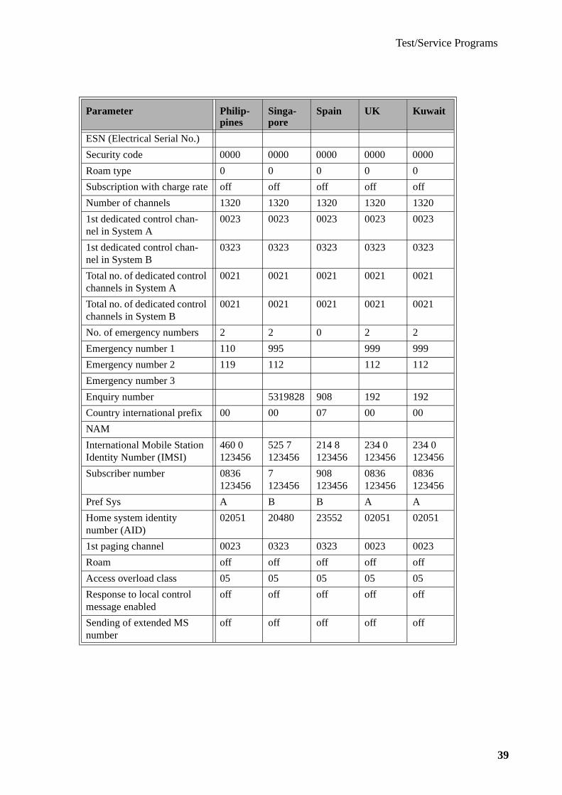
Test/Service Programs
39
Parameter Philip-pines
Singa-pore
Spain UK Kuwait
ESN (Electrical Serial No.)
Security code 0000 0000 0000 0000 0000
Roam type 0 0 0 0 0
Subscription with charge rate off off off off off
Number of channels 1320 1320 1320 1320 1320
1st dedicated control chan-nel in System A
0023 0023 0023 0023 0023
1st dedicated control chan-nel in System B
0323 0323 0323 0323 0323
Total no. of dedicated control channels in System A
0021 0021 0021 0021 0021
Total no. of dedicated control channels in System B
0021 0021 0021 0021 0021
No. of emergency numbers 2 2 0 2 2
Emergency number 1 110 995 999 999
Emergency number 2 119 112 112 112
Emergency number 3
Enquiry number 5319828 908 192 192
Country international prefix 00 00 07 00 00
NAM
International Mobile Station Identity Number (IMSI)
460 0 123456
525 7 123456
214 8 123456
234 0 123456
234 0 123456
Subscriber number 0836 123456
7 123456
908 123456
0836 123456
0836 123456
Pref Sys A B B A A
Home system identity number (AID)
02051 20480 23552 02051 02051
1st paging channel 0023 0323 0323 0023 0023
Roam off off off off off
Access overload class 05 05 05 05 05
Response to local control message enabled
off off off off off
Sending of extended MS number
off off off off off

Test/Service Programs
40
Quick NAM Programming
The number of programmable parameters available in Quick NAM Programming is defined, as earlier described, in ETACS Service Program (NAM & Quick NAM).The parameters below are the available Quick NAM Programmable Parameters as set by default.
Programmable Parameters
Electrical Serial Number (ESN)The ESN, which is a unique binary number that identifies the MS to the cellular sys-tem, is set by the factory and can not be modified.
Subscription with Charge RateThis parameter determines whether AirTime/CallCharge is selectable by the user.
Country International PrefixPrefix required when dialing an international call.This parameter detects an international call at call restrictions.
International Mobile Station Identity (IMSI)This IMSI identity is a 10-digit number composed of three parts:- MNC (Mobile Network Code), 3 digits- MCC (Mobile Country Code), 1 digit- MSIN (Mobile Station Identification Number), 6 digits
Subscriber NumberThe subscriber number may include from 0 up to 10 digits.
Home System Identity Number (AID)This identity number states the subscriber home system and is provided by the sub-scription operator.
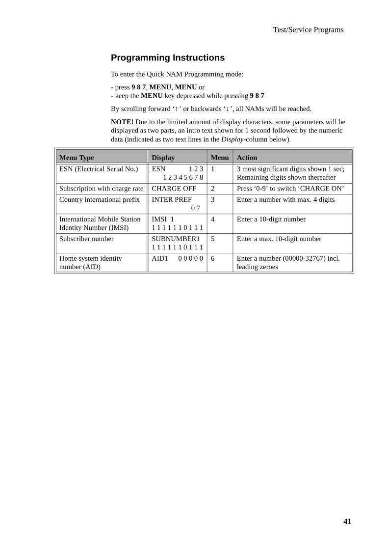
Test/Service Programs
41
Programming Instructions
To enter the Quick NAM Programming mode:
- press 9 8 7, MENU , MENU or- keep the MENU key depressed while pressing 9 8 7
By scrolling forward ‘↑’ or backwards ‘↓’, all NAMs will be reached.
NOTE! Due to the limited amount of display characters, some parameters will be displayed as two parts, an intro text shown for 1 second followed by the numeric data (indicated as two text lines in the Display-column below).
Menu Type Display Menu Action
ESN (Electrical Serial No.) ESN 1 2 3 1 2 3 4 5 6 7 8
1 3 most significant digits shown 1 sec;Remaining digits shown thereafter
Subscription with charge rate CHARGE OFF 2 Press ‘0-9’ to switch ‘CHARGE ON’
Country international prefix INTER PREF 0 7
3 Enter a number with max. 4 digits
International Mobile Station Identity Number (IMSI)
IMSI 11 1 1 1 1 1 0 1 1 1
4 Enter a 10-digit number
Subscriber number SUBNUMBER11 1 1 1 1 1 0 1 1 1
5 Enter a max. 10-digit number
Home system identity number (AID)
AID1 0 0 0 0 0 6 Enter a number (00000-32767) incl. leading zeroes
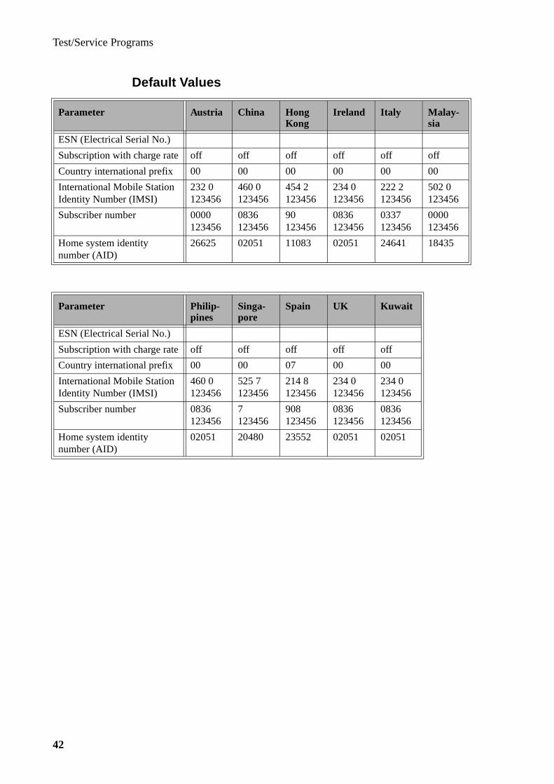
Test/Service Programs
42
Default Values
Parameter Austria China HongKong
Ireland Italy Malay-sia
ESN (Electrical Serial No.)
Subscription with charge rate off off off off off off
Country international prefix 00 00 00 00 00 00
International Mobile Station Identity Number (IMSI)
232 0 123456
460 0 123456
454 2 123456
234 0 123456
222 2 123456
502 0 123456
Subscriber number 0000 123456
0836 123456
90 123456
0836 123456
0337 123456
0000 123456
Home system identity number (AID)
26625 02051 11083 02051 24641 18435
Parameter Philip-pines
Singa-pore
Spain UK Kuwait
ESN (Electrical Serial No.)
Subscription with charge rate off off off off off
Country international prefix 00 00 07 00 00
International Mobile Station Identity Number (IMSI)
460 0 123456
525 7 123456
214 8 123456
234 0 123456
234 0 123456
Subscriber number 0836 123456
7 123456
908 123456
0836 123456
0836 123456
Home system identity number (AID)
02051 20480 23552 02051 02051

Test/Service Programs
43
Flash Pro grammin g
Introduction
The Ericsson Mobile Maintenance Applications (EMMA) flash program is a tool used for upgrading and recovery of the software for the new generation of Ericsson mobile phones.
This description of the EMMA flash program includes information on:
• hardware requirements
• software setup
• hardware setup
• flashing instructions
Hardware Requirements
The following equipment is required when using the EMMA flash program for the Ericsson mobile phones:
• PC with Windows 3.1 (or later) operating system
• COM port (COM1 - COM4) available on the PC
• Programming cable, KRY 101 1135/10 R1A
• Programming interface, NTZ 112 311
• Adaptor, 25- to 9-pin; for PC equipped with a 9-pin COM-connector
( not supplied by Ericsson)
Software Setup
The EMMA program consists of two separate programs,
• the SHELL, one program common for all phone models based on this platform
• the FLASHER, one program for each phone model
which are installed in the above sequence.
Note! The installation procedure below describes how to install the EMMA flash program by using standard floppy disks, but the program may become distributed in other media formats.

Test/Service Programs
44
Installing the Shell Program
It is not possible to install a Flasher program unless the Shell program first has been installed on the local hard disk or a network server.
To install the Shell program, proceed as follows:
4. Close all active windows and insert the Shell disk.
5. In the Program Manager window, click on File and Run, type a:setup in the Command Line box, and click OK.
6. After a while, some important information is displayed.Read the information and click Next >.
7. The shell program suggests a Destination Location in the directory C:\emma\If convenient, click Next >.If not convenient, click Browse, select a suitable directory, and click Next >.
8. The copying of files is begun and also displayed by several graphs.
9. After completion of the file copying, the installation of the Shell program is ended, but additional information can be retrieved by clicking Yes to the question Do you want to view the README file now?
10.Confirm the completion by clicking OK in the Information window and remove the disk.
Note! The path and name of the Shell location directory must not be altered after completed installation.
Installing a Flasher Program
After having the Shell program installed, the Flasher programs of various phones based on the same platform are easily added:
1. Close all active windows and insert a Flasher disk.
2. In the Program Manager window, click on File and Run,type a:setup in the Command Line box, and click OK.
3. After a while, some important information is displayed.Read the information and click Next >.
4. The Flasher program suggests a path and subdirectory where the flasher pro-gram is placed.If convenient, click Next >.If not, click Browse, select a directory path that corresponds with the Shell loca-tion register, and click Next >.
5. The copying of files is begun and also displayed by several graphs.
6. After completion of the file copying, the installation of the Flasher program is ended. Confirm the completion by clicking OK in the Information window and remove the disk.
7. In the Program Manager a new window, EMMA, has been created, from which the Flasher program now can be opened and started by clicking on the group icon ETACS Flash.
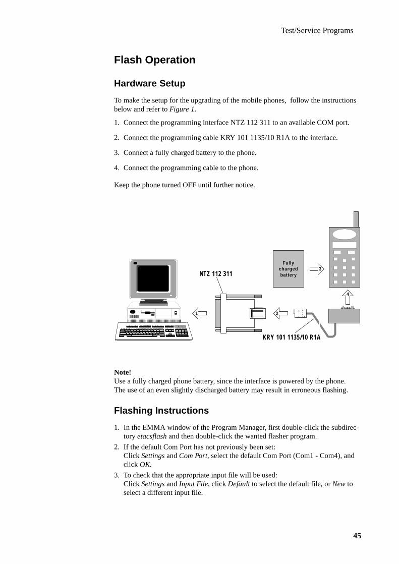
Test/Service Programs
45
Flash Operation
Hardware Setup
To make the setup for the upgrading of the mobile phones, follow the instructions below and refer to Figure 1.
1. Connect the programming interface NTZ 112 311 to an available COM port.
2. Connect the programming cable KRY 101 1135/10 R1A to the interface.
3. Connect a fully charged battery to the phone.
4. Connect the programming cable to the phone.
Keep the phone turned OFF until further notice.
Note!Use a fully charged phone battery, since the interface is powered by the phone.The use of an even slightly discharged battery may result in erroneous flashing.
Flashing Instructions
1. In the EMMA window of the Program Manager, first double-click the subdirec-tory etacsflash and then double-click the wanted flasher program.
2. If the default Com Port has not previously been set:Click Settings and Com Port, select the default Com Port (Com1 - Com4), and click OK.
3. To check that the appropriate input file will be used:Click Settings and Input File, click Default to select the default file, or New to select a different input file.
KRY 101 1135/10 R1A
NTZ 112 311
2
4
1
3Fully
chargedbattery

Test/Service Programs
46
4. Check that the phone is connected to the PC with a fully charged battery as described on previous page.
5. Click Start to enter the flashing dialogue.If required, a Com Port different to the default port can be temporarily selected. The baud rate, 9600, is controlled by the program and can not be manu-ally altered.
6. Press the On/Off-key on the phone and click immediately Start to start flashing.Transfering hex load file is displayed.The flash memory is erased after which the actual flash programming process is begun and also displayed by a graph.
7. After completion, click OK to confirm SUCCESSFUL FLASHING!, disconnect the phone and, if required, connect an identical phone, and repeat the procedure as from step 5.
8. Exit the EMMA flash program.
Note! If the flash programming is not succesful or has become interrupted during the flashing process, the flash connector and phone battery have to be disconnected and reconnected before the flashing can be resumed.

Service InstructionsEricsson Mobile Phone EF738

Service Instructions
2

Service Instructions
3
Contents
System Connector Signals ____________________________ 5
Disassembly________________________________________ 6
Reassembly ________________________________________ 7Flip Mount Inspection______________________________________ 8Warranty Seal ____________________________________________ 8
Exchanging the Circuit Board_________________________ 9
Fault Finding and Alignment ________________________ 10Sequence of Adjustments __________________________________ 11
Item 1: VCTCXO ____________________________________________ 11Item 2: RSSI Calibration ______________________________________ 12Item 3: RF Output Power ______________________________________ 13Item 4: Maximum Deviation ___________________________________ 14Item 5: Nominal Deviation_____________________________________ 15Item 6: SAT Deviation ________________________________________ 16Item 7: TX Data Deviation _____________________________________ 17Item 8: AFMS and Harmonic Distortion __________________________ 18Item 9: Receiver Sensitivity ____________________________________ 19

Service Instructions
4
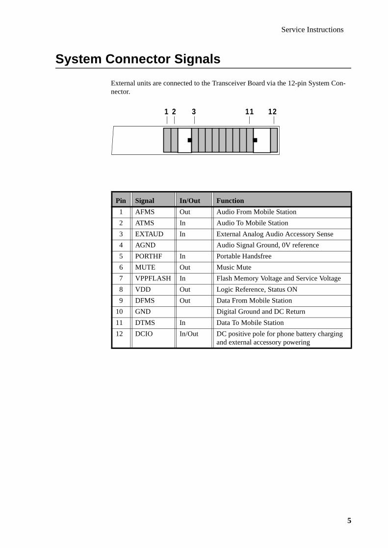
Service Instructions
5
System Connector Si gnals
External units are connected to the Transceiver Board via the 12-pin System Con-nector.
Pin Signal In/Out Function
1 AFMS Out Audio From Mobile Station
2 ATMS In Audio To Mobile Station
3 EXTAUD In External Analog Audio Accessory Sense
4 AGND Audio Signal Ground, 0V reference
5 PORTHF In Portable Handsfree
6 MUTE Out Music Mute
7 VPPFLASH In Flash Memory Voltage and Service Voltage
8 VDD Out Logic Reference, Status ON
9 DFMS Out Data From Mobile Station
10 GND Digital Ground and DC Return
11 DTMS In Data To Mobile Station
12 DCIO In/Out DC positive pole for phone battery chargingand external accessory powering
1 2 3 11 12

Service Instructions
6
Disassembl y
1. Remove the battery and the antennaBefore opening the unit for further disassembly, make sure that the parts can be placed on a dust-free ESD-protected surface.NOTE! Do not touch the display with your fingers!
2. Place the phone on its front and remove four screws with the appropriate torx screwdrivers.
3. Remove the back cover carefully from underneath.
4. Loosen the remaining screws (6, 10).Be careful not to damage the antenna connector (7).
5. Carefully remove the board (1) from the front cover (2) by lifting it upwards.
6. Remove the keypad (4).

Service Instructions
7
Reassembl y
1. Place a front cover (2) on the workbenchAssemble the keypad (4).
2. Carefully place the board (1) into the front cover with the shield can upwards.NOTE! Do not touch the display with your fingers
3. Drop a screw (10) into the upper right corner hole in the board.Tighten the screw with a screwdriver (0.15Nm).
4. Drop an antenna connector (7) into the placement cavity of the antenna connec-tor placement guide.Ensure that the locating posts of the antenna connector are positioned in the mat-ing holes of the board.
5. Drop a screw (6) into the screw hole in the antenna connector.Tighten the screw with a scredriver (0.15Nm).
6. Mount the back cover (13) on the front cover (12).Hold down the lower part of the back cover against the front cover and press the upper part of the phone together.
7. Drop the four screws (14) into the holes on the back cover.Tighten the screws with a screwdriver (0.15Nm).
8. Mount the antenna by screwing it clockwise into the thread.
9. Insert the battery pack into the phone and push until a click is heard.

Service Instructions
8
Flip Mount Inspection
After mounting the flip;Hold the telephone upside down and check that the flip is not open.The flip must be closed as shown in fig. 1; not open as shown in fig. 2.
Warranty Seal
Place the warranty seal over the right hand torx screw at the bottom.
Fig. 1: Flip Closed
Fig. 2: Flip Open

Service Instructions
9
Exchan ging the Circuit Board
1. Transfer the EEPROM contents of the phone to the PC as described in section 3, Test/Service Programs.
2. Disassemble as previously described in this section.
3. Exchange the board.
4. Reload the EEPROM customer data into the phone.
5. Check the function of the phone and, if necessary, align as described next in Fault Finding and Alignment.

Service Instructions
10
Fault Findin g and Ali gnment
The table below shows information about test points and test data of the radio and logic/audio parts of the board. This information will become an aid in testing as well as fault finding. In general, the following procedure can be used:
1. Align the boards in the sequence stated below.
2. If a specific value cannot be obtained, use the tools mentioned in step 3 below to trace the reason.
3. The built-in Test Program will provide access to the function or signal to become investigated, and any signal data that may be required is found in the section Connectors and Signals, where the distribution of signals at the respective con-nector pins is found.
The telephone is tested, unless otherwise explicitly stated, with DC-power 6.2V supplied via a dummy battery.
TP = Test Program
The above settings are automatically executed when entering the test program.
For detailed information regarding the adjustments, refer to subsection Test Pro-gram in this section.
Channel 1 TP-1:1 (RX = 935.0125MHz, TX = 890.0125MHz)
RF Power Off TP-2:8
AFC Active TP-15:2
Audio Switches On TP-20:3 (TX & RX audio paths unmuted)
SAT Tone Off TP-22:3
Manchester Out Off TP-23:0
Volume 4 TP-25:4 (mid range)
TX Source ATMS TP-27:0
Earpiece External TP-28:2
Compandor Disabled TP-29:0 (disabled)
Softlimiter Off TP-32:0
Green LED Off TP-41:MENU+4:0
Red LED Off TP-41:MENU+5:0
ICTRL Off TP-41:MENU+2:0
Illumination Off TP-41:MENU+6:0
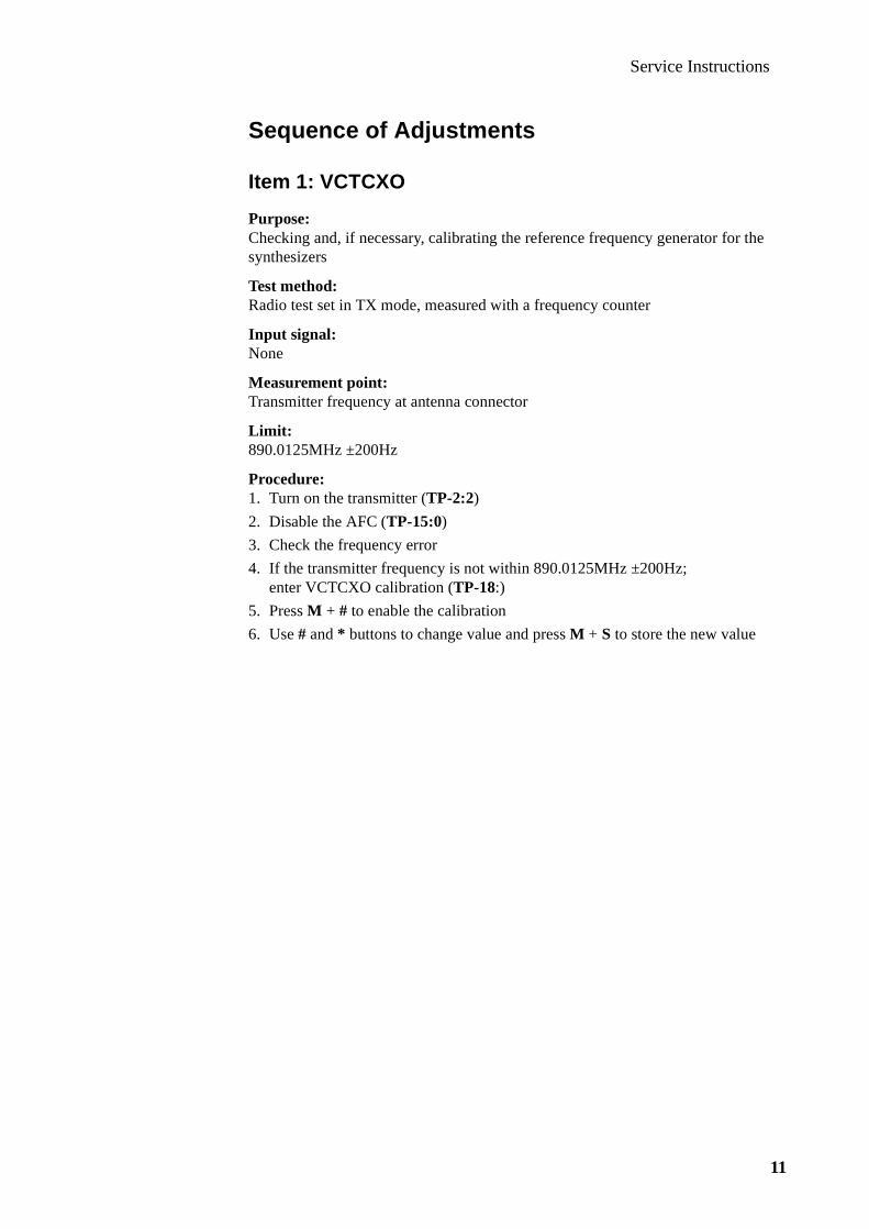
Service Instructions
11
Sequence of Adjustments
Item 1: VCTCXO
Purpose:Checking and, if necessary, calibrating the reference frequency generator for the synthesizers
Test method:Radio test set in TX mode, measured with a frequency counter
Input signal:None
Measurement point:Transmitter frequency at antenna connector
Limit:890.0125MHz ±200Hz
Procedure:1. Turn on the transmitter (TP-2:2)
2. Disable the AFC (TP-15:0)
3. Check the frequency error
4. If the transmitter frequency is not within 890.0125MHz ±200Hz;enter VCTCXO calibration (TP-18:)
5. Press M + # to enable the calibration
6. Use # and * buttons to change value and press M + S to store the new value

Service Instructions
12
Item 2: RSSI Calibration
Purpose:Calibration of the RSSI (received signal strength indicator)
Test method:Radio test set in RX mode
Input signal:Apply 935.0125MHz RF signal modulated with a 1kHz tone at 5.7kHz deviation at a level of -115dBm to the antenna connector
Measurement point:None
Limit:-115dBm 20 < value < 150-107dBm 30 < value < 218-87dBm 50 < value < 279
Procedure:1. Apply 935.0125MHz RF signal modulated with a 1kHz tone at 5.7kHz deviation
at a level of -115dBm to the antenna connector
2. Turn the transmitter on (TP-2:2)
3. Disable the AFC (TP-15:0)
4. Enter RF sensitivity test (TP-9)
5. Press M + S
6. Press M + # to move to next adjustment
7. Set the signal generator to -107dBm
8. Press M + S to store the value
9. Press M + # to move to next adjustment
10.Set the signal generator to -87dBm
11.Press M + S to store the value

Service Instructions
13
Item 3: RF Output Power
Purpose:Checking and, if necessary, calibrating the RF output power
Test method:Radio test set in TX mode
Input signal:None
Measurement point:Output power at the antenna connector measured with an RF power meter
Limit:Power level Output power
2 +26.5dBm ±0.1dB3 +22.5dBm ±0.5dB4 +18.5dBm ±0.5dB5 +14.5dBm ±0.5dB6 +10.5dBm ±0.5dB7 +6.5dBm ±1.0dB
Procedure:1. Turn the transmitter on (TP-2:2-7)
Check if the output power is within the above stated limitsCheck the output power at low (1329), mid (1), and high channels (600)
2. If the output power is not within the above stated limits;use TP-5 to calibrate the output power
3. Press M + # to start the calibration and display power level and calibrated value
4. Use # and * to increase/decrease the output powerPress M + S to store the value and step to next power level
5. Press C to turn off TX, restore channel number, and jump to menu 0 (test input)

Service Instructions
14
Item 4: Maximum Deviation
Purpose:Checking and, if necessary, calibrating the maximum deviation of the transmitter
Test method:Radio test set in TX mode
Input signal:1kHz sine wave signal at 320mVRMS to ATMS (system connector)
Measurement point:At the antenna connector measured with a deviation meter
Tolerance:±7.2kHz -1dB (6.462 - 7.200 kHz)
Procedure:1. Set TXSENS programmable gain stage to nominal value (TP-7, value 7)
2. Enable the compandor (TP-29:1)
3. Connect a 1kHz sine wave signal at 320mVRMS to ATMS (system connector)
4. Turn the transmitter on (TP-2:2)
5. Monitor RF peak deviation
6. If the deviation is outside the limits; adjust the deviation
7. Enter TP-14
8. Start the trimming by pressing M + #
9. Trim audio deviation to 6.462 - 7.200 kHz by pressing # and * to increase/decrease the deviationAllowed trim values are 2 to 13Trim step size is 0.4dB per step
10.Press M + S to store the value
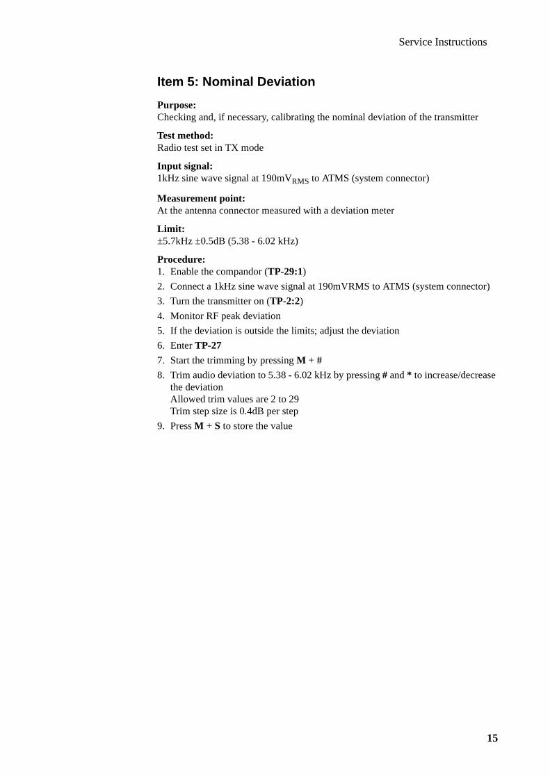
Service Instructions
15
Item 5: Nominal Deviation
Purpose:Checking and, if necessary, calibrating the nominal deviation of the transmitter
Test method:Radio test set in TX mode
Input signal:1kHz sine wave signal at 190mVRMS to ATMS (system connector)
Measurement point:At the antenna connector measured with a deviation meter
Limit:±5.7kHz ±0.5dB (5.38 - 6.02 kHz)
Procedure:1. Enable the compandor (TP-29:1)
2. Connect a 1kHz sine wave signal at 190mVRMS to ATMS (system connector)
3. Turn the transmitter on (TP-2:2)
4. Monitor RF peak deviation
5. If the deviation is outside the limits; adjust the deviation
6. Enter TP-27
7. Start the trimming by pressing M + #
8. Trim audio deviation to 5.38 - 6.02 kHz by pressing # and * to increase/decrease the deviationAllowed trim values are 2 to 29Trim step size is 0.4dB per step
9. Press M + S to store the value

Service Instructions
16
Item 6: SAT Deviation
Purpose:Checking and, if necessary, calibrating the SAT (Supervisor Audio Tone) deviation of the transmitter
Test method:Radio test set in TX mode
Input signal:None
Measurement point:At the antenna connector measured with a deviation meter
Limit:±1.7kHz ±0.5dB (1.60 - 1.80 kHz)
Procedure:1. Mute the TX audio path (TP-20:0)
2. Activate the SAT-tone (TP-22:1)
3. Unmute the TX SAT path (TP-22:4)
4. Turn the transmitter on (TP-2:2)
5. Monitor the SAT deviation
6. If the deviation is outside the limits; adjust the deviation
7. Enter TP-22
8. Start the trimming by pressing M + #
9. Trim SAT deviation to 1.60 - 1.80 kHz by pressing # and * to increase/decrease the deviationAllowed trim values are 2 to 29Trim step size is 0.3dB per step
10.Press M + S to store the value

Service Instructions
17
Item 7: TX Data Deviation
Purpose:Checking and, if necessary, calibrating the TX data deviation of the transmitter
Test method:Radio test set in TX mode
Input signal:None
Measurement point:At the antenna connector measured with a deviation meter
Limit:±6.4kHz ±0.5dB (6.021 - 6.780 kHz)
Procedure:1. Mute the TX audio path (TP-20:0)
2. Activate the TX Data (TP-23:1)
3. Turn the transmitter on (TP-2:2)
4. Monitor the TX data deviation
5. If the deviation is outside the limits; adjust the deviation
6. Enter TP-23
7. Start the trimming by pressing M + #
8. Trim TX Data Deviation to 6.021 - 6.780 kHz by pressing # and * to increase/decrease the deviationAllowed trim values are 2 to 13Trim step size is 0.4dB per step
9. Press M + S to store the value

Service Instructions
18
Item 8: AFMS and Harmonic Distortion
Purpose:Checking and, if necessary, calibrating the deviation of the receiver
Test method:Radio test set in RX mode
Input signal:Apply a -50dBm 935.0125MHz RF signal modulated with a 1kHz tone, ±2.3kHz deviation to the antenna input
Measurement point:At the AFMS output from the system connector measured with an AC volt meter
Limit:25mV ±1.5dB (21.035 - 29.710 mV)
Procedure:1. Enable the compandor (TP-29:1)
2. Apply a -50dBm 935.0125MHz RF signal modulated with a 1kHz tone, ±2.3kHz deviation to the antenna input
3. Monitor the AFMS output with a 100kΩ load
4. If AFMS is outside the limits; adjust the AFMS level
5. Enter TP-10
6. Start the trimming by pressing M + #
7. Trim the AFMS level by pressing # and * to increase/decrease
8. Press M + S to store the value
9. Measure the receiver harmonic distortion
10.Should be less than 4.5% at AFMS using a CCITT filter
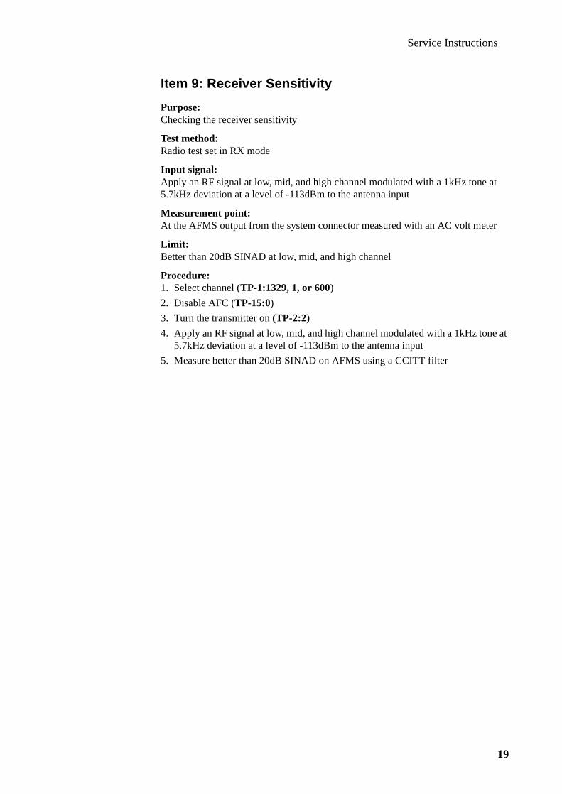
Service Instructions
19
Item 9: Receiver Sensitivity
Purpose:Checking the receiver sensitivity
Test method:Radio test set in RX mode
Input signal:Apply an RF signal at low, mid, and high channel modulated with a 1kHz tone at 5.7kHz deviation at a level of -113dBm to the antenna input
Measurement point:At the AFMS output from the system connector measured with an AC volt meter
Limit:Better than 20dB SINAD at low, mid, and high channel
Procedure:1. Select channel (TP-1:1329, 1, or 600)
2. Disable AFC (TP-15:0)
3. Turn the transmitter on (TP-2:2)
4. Apply an RF signal at low, mid, and high channel modulated with a 1kHz tone at 5.7kHz deviation at a level of -113dBm to the antenna input
5. Measure better than 20dB SINAD on AFMS using a CCITT filter

Service Instructions
20

AccessoriesEricsson Mobile Phone EF738

Accessories
2

Accessories
3
Contents
Rapid Charger _____________________________________ 7Introduction ______________________________________________ 7Main Features ____________________________________________ 7
Versions ____________________________________________________ 8Connectors _______________________________________________ 8
Secondary DC-cord ___________________________________________ 8Specifications _____________________________________________ 8
Travel Charger ___________________________________ 9Introduction ______________________________________________ 9Main Features ____________________________________________ 9
Indicators __________________________________________________ 10Output Characteristics ____________________________________ 10Connector_______________________________________________ 11
Secondary DC-cord __________________________________________ 11Specifications ____________________________________________ 11
Vehicle Power/Charger _____________________________ 13Introduction _____________________________________________ 13Main Features ___________________________________________ 13
Indicators __________________________________________________ 14Output Characteristics ____________________________________ 14Connectors ______________________________________________ 15
Cigarette Lighter Adaptor______________________________________ 15Power Plug _________________________________________________ 15
Specifications ____________________________________________ 15
Continued on next page
Accessories
4
DeskTop Charger MC7000 __________________________ 17Introduction______________________________________________17Electronics _______________________________________________18
Central Processing Unit _______________________________________ 18Supply Current Monitor _______________________________________ 19Charge Switches _____________________________________________ 19
Front Slot Switch __________________________________________ 19Rear Slot Switch __________________________________________ 19
Voltage Monitors ____________________________________________ 19Front Slot Monitor _________________________________________ 19Rear Slot Monitor _________________________________________ 19
Phone On/Off Status __________________________________________ 20Discharger __________________________________________________ 20LED Indicators ______________________________________________ 20
Front LEDs ______________________________________________ 20Rear LEDs _______________________________________________ 20
Temperature Guard ___________________________________________ 20Power Distribution for Phone Operation ______________________20Battery Charging _________________________________________20
Front Slot Charger____________________________________________ 21Main Charging ____________________________________________ 21Trickle Charging __________________________________________ 21
Rear Slot Charger ____________________________________________ 21Main Charging ____________________________________________ 21Trickle Charging __________________________________________ 21Discharging ______________________________________________ 21
Error Detection ______________________________________________ 22LED Indicators ______________________________________________ 22
Front Indicator - Phone Slot__________________________________ 22Rear Indicator - Spare Battery Slot ____________________________ 22
Specifications_____________________________________________22Connectors and Signals ____________________________________23
System Bus Connector ________________________________________ 23Front Slot __________________________________________________ 23Rear Slot ___________________________________________________ 24
Portable HandsFree ________________________________ 25Introduction______________________________________________25Portable HandsFree Features _______________________________25Specifications_____________________________________________26
Microphone_________________________________________________ 26Earphone ___________________________________________________ 26
Connector and Signals _____________________________________26
Continued on next page

Accessories
5
Vehicle HandsFree Solution HF7300 __________________ 27Introduction _____________________________________________ 27HandsFree Features ______________________________________ 27HandsFree Components ___________________________________ 28
Cradle _____________________________________________________ 28Stick-On Microphone _________________________________________ 28External Speaker_____________________________________________ 28HandsFree Unit______________________________________________ 28
Microphone Amplifier______________________________________ 29Speaker Amplifier _________________________________________ 29Modem/Handset Option ____________________________________ 29Audio Switch Control ______________________________________ 29External Audio Control _____________________________________ 29Music Mute Control _______________________________________ 29Power Supply_____________________________________________ 30
Optional Accessories ______________________________________ 30Music Mute_________________________________________________ 30Goose-Neck Microphone ______________________________________ 30Data Extension ______________________________________________ 30External Handset_____________________________________________ 30
Specifications ____________________________________________ 31HandsFree Unit______________________________________________ 31Cradle _____________________________________________________ 31
Connectors and Signals____________________________________ 32Holder _____________________________________________________ 32
System Connector _________________________________________ 32HandsFree Unit______________________________________________ 32
System Connector J1 _______________________________________ 33Power Connector J2________________________________________ 33Microphone Connector J4 ___________________________________ 34Music Mute Connector J5 ___________________________________ 34Data Communication Connector J6____________________________ 34Speaker Connector J7 ______________________________________ 34
Continued on next page

Accessories
6
Vehicle HandsFree Solution HF7600 __________________ 35Introduction______________________________________________35HandsFree Features _______________________________________35
Echo Cancellation ____________________________________________ 36Noise Reduction _____________________________________________ 36
HandsFree Components____________________________________36Cradle _____________________________________________________ 36Stick-On Microphone _________________________________________ 36External Speaker _____________________________________________ 37Handsfree Unit ______________________________________________ 37
Digital Signal Processor (DSP) _______________________________ 37Audio-To-Mobile-Station ___________________________________ 37Audio-From-Mobile-Station _________________________________ 37Microphone Amplifier ______________________________________ 37Speaker Amplifier _________________________________________ 37Music Mute Control________________________________________ 38Power Supply_____________________________________________ 38
Optional Accessories_______________________________________38Music Mute _________________________________________________ 38Goose-Neck Microphone ______________________________________ 38Data Extension ______________________________________________ 38External Handset_____________________________________________ 39
Specification______________________________________________39Handsfree Unit ______________________________________________ 39Cradle _____________________________________________________ 39
Connectors and Signals ____________________________________40Holder _____________________________________________________ 40
System Connector _________________________________________ 40HandsFree Unit ______________________________________________ 40
System Connector J1 _______________________________________ 41Power Connector J2________________________________________ 41Microphone Connector J4 ___________________________________ 42Music Mute Connector J5 ___________________________________ 42Data Communication Connector J6____________________________ 42Speaker Connector J7 ______________________________________ 42

Accessories
7
Rapid Char ger
Introduction
The Rapid Charger is a basic charger which converts AC to DC by using a conven-tional transformer followed by a rectifying circuitry. This charger can consequently not be used worldwide, as opposed to a primary switched charger, and will therefor be available in several different versions as listed on next page.
The Rapid Charger consists of:
• AC/DC converter incl. wall plug
• secondary cord with power connector
The AC/DC converter is plugged directly into the mains power outlet and the recti-fied DC voltage/current is distributed via the secondary cord to the power connec-tor, which is plugged into the system connector of the phone.
Main Features
The Rapid Charger can be used as power source in two different ways, for:
• the 7X8-family phones
• the DeskTop Charger MC7000

Accessories
8
Versions
The Rapid Charger is designed in several versions for different mains voltages, fre-quencies, and power outlets as specified below:
Connectors
Secondary DC-cord
Specifications
Type No: 402 0034-UK
Dimensions:- AC/DC-Converter 78 x 42 x 45 mm; 3.1 x 1.7 x 1.8 in (excl. wall plug)- Power Plug 24 x 11 x 11 mm; 0.9 x 0.4 x 0.4 in
Input Voltage Refer to Versions above
Input Frequency: Refer to Versions above
Output Voltage/Current: 6VDC/700mA
Mains voltage Frequency Mains plug
115V ±10% 60Hz ±5% US standard
230V -10% to +6% 50Hz ±5% EU standardUS (Thailand)UK (Hong Kong)
240V -10% to +6% 50Hz ±5% UK standard
240V ±10% 50Hz ±5% AUS standard
GND
VDC
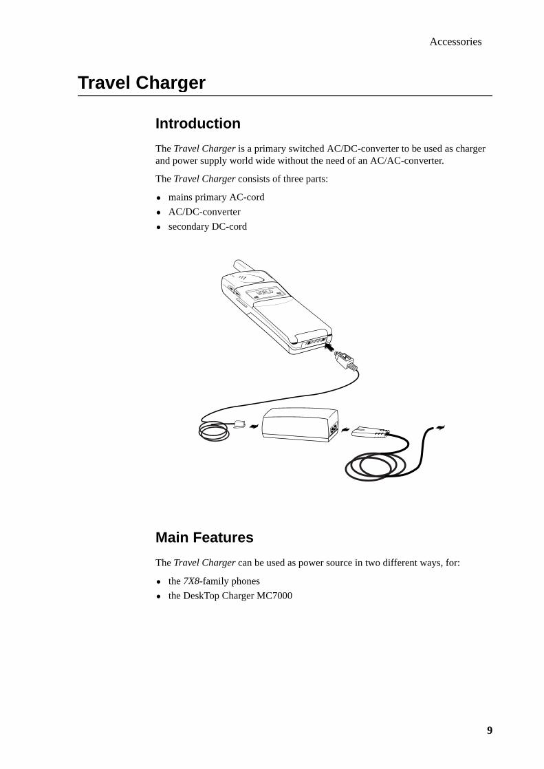
Accessories
9
Travel Char ger
Introduction
The Travel Charger is a primary switched AC/DC-converter to be used as charger and power supply world wide without the need of an AC/AC-converter.
The Travel Charger consists of three parts:
• mains primary AC-cord
• AC/DC-converter
• secondary DC-cord
Main Features
The Travel Charger can be used as power source in two different ways, for:
• the 7X8-family phones
• the DeskTop Charger MC7000

Accessories
10
Indicators
A green LED located next to the secondary DC output is turned on whenever the mains voltage is available on the primary side
Output Characteristics
The output voltage and current of the Travel Charger should after 5 minutes stay within the values indicated as “white” area in the picture below.
VDC
outputconnector
LED
U (V)
I (mA)
8.47.6
600 900
2.0
1000
Output power character ist ics wi th in range
Output power character ist ics out of range
Output power character ist ics wi th in range f i rst 5 minutesOutput power character ist ics out of range af ter 5 minutes

Accessories
11
Connector
Secondary DC-cord
Specifications
Type No: 402 0036-BV
Dimensions:- AC/DC-Converter 95 x 38 x 27 mm; 3.7 x 1.5 x 1.1 in- Power Plug 24 x 11 x 11 mm; 0.9 x 0.4 x 0.4 in
Input Voltage 100 - 240 VAC (±10%)
Input Current: 150mA (typical)
Input Frequency: 50 - 60 Hz (±5%)
Output Voltage/Current: 7.6 VDC/600mA
GND
VDC
GND
VDC
n.c.
n.c.

Accessories
12
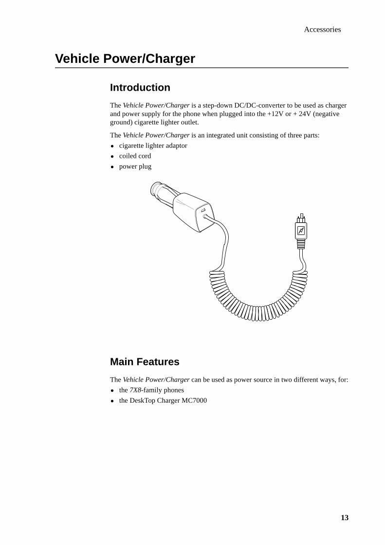
Accessories
13
Vehicle Power/Char ger
Introduction
The Vehicle Power/Charger is a step-down DC/DC-converter to be used as charger and power supply for the phone when plugged into the +12V or + 24V (negative ground) cigarette lighter outlet.
The Vehicle Power/Charger is an integrated unit consisting of three parts:
• cigarette lighter adaptor
• coiled cord
• power plug
Main Features
The Vehicle Power/Charger can be used as power source in two different ways, for:
• the 7X8-family phones
• the DeskTop Charger MC7000
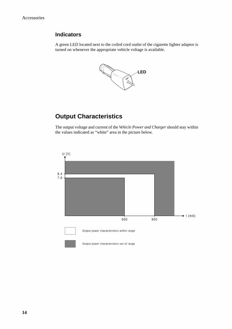
Accessories
14
Indicators
A green LED located next to the coiled cord outlet of the cigarette lighter adaptor is turned on whenever the appropriate vehicle voltage is available.
Output Characteristics
The output voltage and current of the Vehicle Power and Charger should stay within the values indicated as “white” area in the picture below.
LED
U (V)
I (mA)
8.47.6
600 900
Output power character ist ics wi th in range
Output power character ist ics out of range
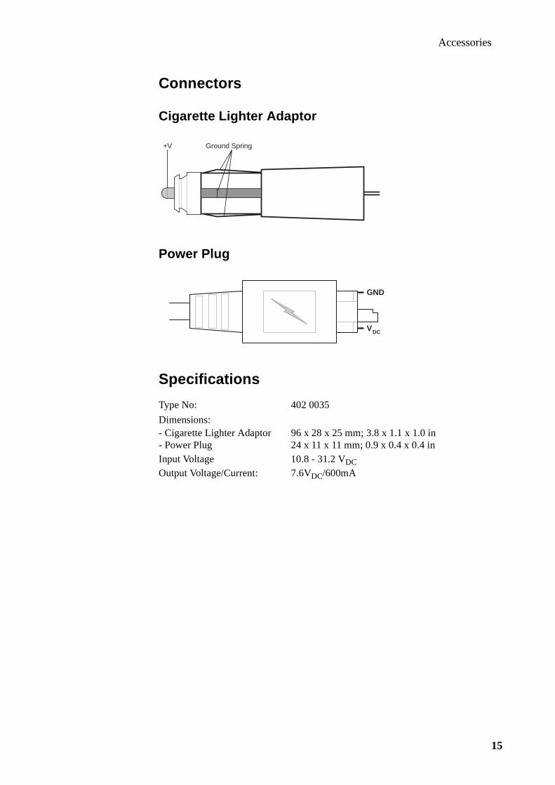
Accessories
15
Connectors
Cigarette Lighter Adaptor
Power Plug
Specifications
Type No: 402 0035
Dimensions:- Cigarette Lighter Adaptor 96 x 28 x 25 mm; 3.8 x 1.1 x 1.0 in- Power Plug 24 x 11 x 11 mm; 0.9 x 0.4 x 0.4 inInput Voltage 10.8 - 31.2 VDC
Output Voltage/Current: 7.6VDC/600mA
Ground Spring+V
GND
VDC

Accessories
16

Accessories
17
DeskTop Char ger MC7000
Introduction
The DeskTop Charger MC7000 is a dual desk charger specially designed for the 7X8-family telephones. The phone is placed in the front slot for simultaneous pow-ering and battery charging, while the spare battery to be charged is placed in the rear slot, which also features a manual discharge/reconditioning facility.
As the MC7000 does not include an internal power supply, an external power source has to be connected to the system bus connector at the rear of the unit.
The external power source should be one of the following Ericsson product:
• Rapid Charger
• Travel Charger
• Vehicle Power/Charger
Furthermore, the Portable HandsFree as well as Mobile Office equipment can be connected to the DeskTop Charger MC7000.

Accessories
18
Electronics
The electronics of the MC7000 is designed around the Central Processing Unit.
Central Processing Unit
The Central Processing Unit (CPU) is equipped with 4kbyte ROM, thus making it possible to control the entire MC7000 charger.
The supply voltage to the CPU is +3.8V which is being derived from a linear volt-age regulator and a crystal generates a 5MHz clock frequency to the oscillator input of the CPU.
The Central Processing Unit interacts with the following major peripheral blocks:
• Supply Current Monitor
• Charge Switches; front & rear
• Voltage Monitors; front & rear
• Phone On/Off Status
• Discharger
• LED Indicators; front & rear
• Temperature Guard
CPU
SupplyCurrentMonitor
TempGuard
FrontChargeSwitch
RearChargeSwitch
FrontLEDs
RearLEDs
PhoneOn/OffStatus
FrontVoltageMonitor
RearVoltageMonitor
SystemBus
Connector
FrontSlot
RearSlot
Dis-charger
ACCDCIO
DCIO
VDD
+V

Accessories
19
Supply Current Monitor
The current distributed from the external power source to the front or rear slot passes through the Supply Current Monitor. The CPU reads the output from the Supply Current Monitor is order to establish whether charging or charging com-pleted is in effect as follows:
>200mA: Charging<200mA: Charging completed
Charge Switches
The current from the external power source to the two slots can independently be switched On/Off by two separate CPU outputs.
Front Slot Switch
This CPU controlled switch is normally On except when the spare battery is being charged.
Rear Slot Switch
The rear slot charging switch is controlled by the second CPU output, which will allow charging of the spare battery only if the phone battery is fully charged or if no phone is inserted in the front slot. This switch goes Off for a short while once every other second for voltage reading purposes.
Voltage Monitors
The CPU controls the Voltage Monitors to enable reading of the battery voltages.
Front Slot Monitor
If the CPU input of the Front Slot Voltage Monitor suddenly detects a voltage at DCIO when the corresponding charge switch is Off, this means that the voltage is coming from the battery, i.e. a phone has been inserted into the slot. This will be detected regardless of whether the phone is turned On or Off. If Off when inserted, the auto-turn-on mode will turn it On.However, if the phone is removed during charging, e.g. when a call is received, this will not be detected as this input still will read a voltage, now coming from the external power source. (See Phone On/Off Status on next page)
Rear Slot Monitor
The Rear Slot Voltage Monitor detects whether the spare battery requires charging. During the charging the current is switched off for a short while every other second in order to read the battery voltage and in this way establish whether the battery is fully charged or not. The CPU is in this way also informed if the battery is removed during the charging process.
Accessories
20
Phone On/Off Status
The VDD input indicates whether the phone is Off or On and will inform the CPU if the phone has been removed during charging.
Discharger
To prolong the battery life the rear slot is equipped with a reconditioning feature.By pressing the discharge switch (same as the rear LED indicator), the CPU becomes notified that it will have to carry out a discharge operation on the battery in the rear slot.The CPU then activates the discharge operation by draining the battery at a suitable resistive load.
LED Indicators
The LEDs are used for indication of the various charging phases.
Front LEDs
The two front LEDs (green and red) can be On and Off in any combination except both On.
Rear LEDs
The two rear LEDs (green and red) can be On and Off in any combination.
Temperature Guard
A temperature related voltage is generated due to an onboard NTC resistor and fed to an input of the CPU for detection and measures to prevent overheating. The threshold is set to +55°C onboard corresponding to an ambient temperature of +35°C.
Power Distribution for Phone Operation
The power to the front slot for phone operation is entirely controlled by the phone.The various current values needed in different situations, like stand-by or transmis-sion, are programmed and stored in the telephone.The MC7000 is able to deliver 500 - 700 mA to the phone depending on the power source is being connected.
Battery Charging
The charging of both batteries is turned on and off by a switch circuitry which is controlled by the Central Processing Unit. Charging is only possible for one slot at a time where the front slot has got highest priority, i.e. charging of the spare battery will not begin until the phone battery is fully charged or removed.
The batteries being used are four 1.2V cell NiMH (Nickel-Metal-Hydride) or NiCd (Nickel-Cadmium) chargeable batteries, without internal thermistor.

Accessories
21
Front Slot Charger
Main Charging
The charging is entirely controlled by the phone, which after being inserted into the charger slot starts being charged by the MC7000. Any possible charging of a spare battery in the rear slot is interrupted, and 500 - 700 mA is delivered to the phone battery.
Note! The phone does not have to be turned On when inserted into the charger slot due to its auto-turn-on feature.
Trickle Charging
After the main charging the phone automatically returns to normal power distribu-tion and trickle charging unless a spare battery then is going to be charged. The power distribution and trickle charging to the phone is in that case inhibited until the spare battery charging is terminated.
Rear Slot Charger
Main Charging
The 500 - 700 mA charging current to the spare battery is entirely controlled by the Central Processing Unit. Several algorithms are used to establish when the battery is fully charged:
• -dv/dtThe battery voltage is sampled once a second for approximately one minute and the mean value is calculated. The max. mean value is stored and compared with consecutive values. When a specific divergence is obtained, the charging is ter-minated.
• peak detectThe charging is terminated when the above mentioned values are less or identical to the max. mean value for a specific time.
• safety time elapsed (4 hours)The safety timer is used as a last resort when the above methods fail.
Trickle Charging
When the main charging is completed an 8mA trickle charging generated by short pulses is automatically initiated, but only in case the front slot is empty.
Discharging
After pressing the discharge button the spare battery is discharged by a 200mA cur-rent. Charging will commence when the battery voltage has dropped to 4.0V.

Accessories
22
Error Detection
An error is indicated and charging is halted for 20 minutes when the ambient tem-perature is higher than +35°C.
LED Indicators
Front Indicator - Phone Slot
Rear Indicator - Spare Battery Slot
Specifications
Status Significance Detection
Off No phone Front Voltage Monitor or Phone On/Off Status
Red Charging Supply Current Monitor >200mA
Green Charging complete Supply Current Monitor <200mA
Status Significanse Detection
Off No battery Rear Voltage Monitor
Red Charging Rear Voltage Monitor
Green Charging complete Rear Voltage Monitor
Yellow Discharging Discharge Switch
Red flash Temperature error Temperature Guard
Battery type Charging time - Front Charging time - Rear
NiMH 650mAh: ≈1h50min ≈ 1h25min
Type No.: 402 0040-BV402 0040-UK
Dimensions: 73 x 90 x 47 mm2.9 x 3.5 x 1.9 in
Input voltage: 7 - 10 VDC
Ambient temp: +5°C to +35°C+41°F to +95°F

Accessories
23
Connectors and Signals
System Bus Connector
1) System Bus Connector2) Front Slot Connector
Front Slot
Note: For pin assignments, refer to System Bus Connector above
Pin Signal Specification
1 AFMS Audio-from-mobile-station
2 ATMS Audio-to-mobile-station
3 EXTAUD External analog audio accessory sense
4 AGND Audio signal ground, 0V refernce
5 PORTHF Portable handsfree
6 MUTE Music mute
7 VPPFLASH Flash memory voltage and service voltage
8 VDD Logic reference, status On
9 DFMS Data from mobile station
10 DGND Digital ground and DC return
11 DTMS Data to mobile station
12 ACCDCIO1)
DCIO2)DC positive pole for phone battery charging and exter-nal accessory powering
1 2 3 11 12
1 12
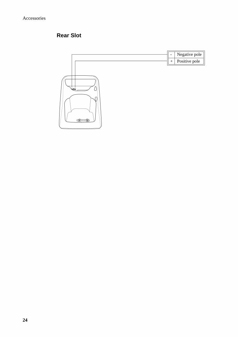
Accessories
24
Rear Slot
- Negative pole
+ Positive pole

Accessories
25
Portable HandsFree
Introduction
The Portable HandsFree is a light-weight unit which allows the user to combine the mobility of a handheld phone with the advantages of being handsfree.The following three main components are included:
• microphone
• earphone
• connector
The connector is plugged into the system connector of the phone. After fitting the earphone and attaching the microphone clip to a suitable part of the clothing, the portable handsfree facility is ready to be used.
Portable HandsFree Features
The Portable HandsFree is designed to be used with all phones in the Ericsson 7X8-family.
The portable handsfree communication is full duplex, i.e. both parties will be able to talk simultaneously.

Accessories
26
Specifications
Microphone
Earphone
Connector and Signals
Type No.: 502 0013-BV
Characteristics: Omnidirectional
Sensitivity: -43.5dB ±3dB rel. 1V/Pa at 1kHz
Impedance: ≤ 2kΩS/N ratio: ≥ 35dB
Sensitivity: 106dB/250mV at 1kHz
Impedance: 16Ω
Portable HF connector Signal direction System connector
MIC ATMS
EAR AFMS
GND GND
PORTHF (actice LO) PORTHF (detect)
MIC
EAR
GND
PORTHF

Accessories
27
Vehicle HandsFree Solution HF7300
Introduction
The Vehicle Handsfree Solution HF7300 is specially designed for the Ericsson 7X8-family telephones and includes apart from the handsfree facilities also a power sup-ply for battery charging and phone operation.
The four main components are:
• Cradle
• Stick-On Microphone
• External Speaker
• Handsfree Unit
HandsFree Features
The HandsFree Unit does not include a DSP (digital signal processor) as the CPU (Central Processing Unit) of the telephone handles the handsfree switching.
The handsfree function is semi-duplex, which only permits one party to talk at a time while the other party is switched off to avoid feedback. When the land side party is talking, a "comfort noise" is added to simulate the background noise heard from the mobile.

Accessories
28
HandsFree Components
Cradle
The cradle consists of two sub-units, the Cradle Attachment and the Holder.
The Cradle is equipped with a slide joint which is adjusted during the installation to a suitable vertical and horizontal angle for easy reach of the phone. The snap/click-in Holder connects the phone to the HandsFree Unit.
Stick-On Microphone
The Stick-On Microphone included in the kit is a unidirectional microphone to be mounted in a fixed position in the vehicle and connected to the HandsFree Unit.
External Speaker
Unless an optional Music Mute unit is utilised, the 4Ω External Speaker has to be connected to the speaker amplifier output of the HandsFree Unit.
HandsFree Unit
The HandsFree Unit includes the following electronic blocks:
• Microphone Amplifier
• Speaker Amplifier
• Modem/Handset Option
• Audio Switch Control
• External Audio Control
• Music Mute Control
• Power Supply
Cradle Attachment
Holder
Accessories
29
Microphone Amplifier
The Microphone Amplifier has got two individual inputs for the two types of micro-phones being available:
• Stick-On microphone (standard)
• Goose-Neck microphone (optional)
The microphone signal passes through two amplifier stages which results in a total gain of 31dB and 21dB for the Stick-On and Goose-Neck microphone resp.
Speaker Amplifier
The AFMS (audio-from-mobile-station) signal received from the phone is amplified by a programmable gain amplifier and fed to a differential amplifier consisting of four power transistors resulting in a total gain of 21dB. To protect the power transis-tors and the speaker against high current, a feed back signal from the power transis-tors to the programmable amp will allow only short peaks of high current to get through but reduce continuous high current to approximately 1.2A corresponding to just about 5W output power.
Modem/Handset Option
The Data Communication connector can be utilised for connection of two different options:
• analog PCMCIA modem
• external handset
When any of these devices is connected the audio signal ATMS (Audio-To-Mobile-Station) is switched to this connector, while AFMS (audio-from-mobile-station) always is available.
Note: A Data Extension Unit is required for the connection between the optional unit and the Data Communication connector.
Audio Switch Control
The Audio Multiplexer Control is used to switch the audio paths between the exter-nal microphone and the modem/handset connector.
Control signals such as EXTAUD (external audio control) and MUTEINV (inverted mute) are derived from logical gates controlled by the signals PORTHF (portable handsfree), DV (data/voice), and HOOKSNS (hook sense).
External Audio Control
The EXTAUD (external audio control) signal informs the phone when an accessory which is using the two external audio signals AFMS and ATMS has been connected to the HandsFree Unit
Music Mute Control
An optional Music Mute unit can be supplied with +12V from the vehicle battery. The Music Mute function is controlled from the phone by the MUTE signal which is
Accessories
30
inverted by an open collector transistor before becoming available at two of the con-nectors.
Power Supply
The Handsfree Unit is able to deliver power to the phone for operation and battery charging by regulating the +12V of the vehicle battery to a constant current supply of max. 850mA and less than 1mA during stand-by.
Phone Operation:
The power consumption of the phone in different situations, e.g. in stand-by or in transmission, is entirely controlled by the phone itself, as these power levels are pro-grammed and stored in the phone.
Battery Charger:
As the phone battery at all times is provided with current from the HandsFree Unit, the charging of the battery, incl. trickle charging, is controlled by the phone itself.
For more information regarding the battery charging algorithms of the telephone, refer to section 2, Technical Description, subsection Battery Charging.
Optional Accessories
Music Mute
An optional Music Mute unit can be connected to the HandsFree Unit and will direct the amplified received audio signal to the car stereo speakers during the handsfree conversation.
If the car stereo is equipped with a specific “mute” input, the optional Music Mute Cable connected directly between this input and the HandsFree Unit will mute the car stereo during the handsfree conversation.
Note: Max. current load at Music Mute output is 200mA.
Goose-Neck Microphone
A Goose-Neck Microphone allows a more flexible microphone position for improved sound quality incl. reduction of transmitted noise.
Data Extension
Data communication using handsfree mode is made possible by connecting a Data Extension Unit between a modem and the Data Communication Connector.
External Handset
An External Handset will give the user the possibility to switch from handsfree to handheld operation without disconnecting the power source. A Data Extension Unit is required for the connection between the External Handset and the Data Commu-nication Connector.

Accessories
31
Specifications
HandsFree Unit
Cradle
Type No: 502 0019-BV
Dimensions: 135 x 100 x 28 mm; 5.3 x 3.9 x 1.1 in
Input Voltage: 10.8 to 15.6 VDC
Ambient Temperature - Operating: -25oC to +60oC; -13oF to +140oF
Ambient Temperature - Charging: +10oC to +35oC; +50oF to +95oF
Weight: 105g; 3.7 oz
Height: 95mm; 3.7 in
Depth (incl. cradle attachment): 54mm; 2.1 in
Width: 60mm; 2.4 in

Accessories
32
Connectors and Signals
Holder
System Connector
Note: For pin assignments, refer to column H-pin of System Connector J1 table on next page.
HandsFree Unit
1 12
J4 J7 J6 J1 J2J5
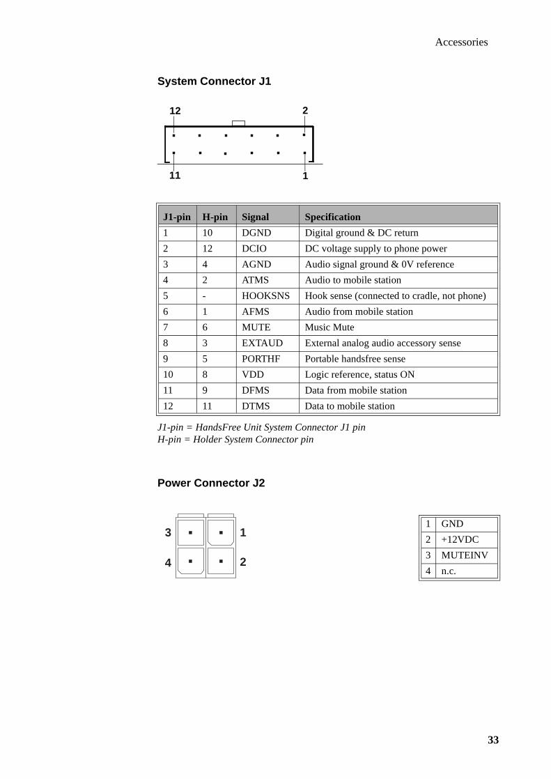
Accessories
33
System Connector J1
J1-pin = HandsFree Unit System Connector J1 pinH-pin = Holder System Connector pin
Power Connector J2
J1-pin H-pin Signal Specification
1 10 DGND Digital ground & DC return
2 12 DCIO DC voltage supply to phone power
3 4 AGND Audio signal ground & 0V reference
4 2 ATMS Audio to mobile station
5 - HOOKSNS Hook sense (connected to cradle, not phone)
6 1 AFMS Audio from mobile station
7 6 MUTE Music Mute
8 3 EXTAUD External analog audio accessory sense
9 5 PORTHF Portable handsfree sense
10 8 VDD Logic reference, status ON
11 9 DFMS Data from mobile station
12 11 DTMS Data to mobile station
1 GND
2 +12VDC
3 MUTEINV
4 n.c.
12
11
2
1
3
4
1
2

Accessories
34
Microphone Connector J4
Microphone connector J4 is femalePicture shows corresponding male
Music Mute Connector J5
Music Mute connector J5 is malePicture shows corresponding female
Data Communication Connector J6
Speaker Connector J7
Speaker connector J7 is femalePicture shows corresponding male
1 +10dB Stick-On microphone
2 0dB Goose-Neck microphone
3 AGND Signal ground
1 LSP- Loudspeaker common
2 DGND Digital ground & DC return
3 LSP+ Loudspeaker signal
4 MUTE Music mute
5 DC12OUT +12VDC output
1 MUTEINV Music Mute (inverted)
2 VDD Logic reference, status ON
3 DC12OUT +12VDC output
4 AFMS (RX) Audio from mobile station
5 D/V Data/voice signal
6 ATMS (TX) Audio to mobile station
7 PORTHF Portable handsfree sense
8 DTMS Data to mobile station
9 DFMS Data from mobile station
10 DGND Digital ground & DC return
1 LSP+ Loudspeaker signal
2 LSP- Loudspeaker common
3 n.c.

Accessories
35
Vehicle HandsFree Solution HF7600
Introduction
The Vehicle Handsfree Solution HF7600 is specially designed for the Ericsson 7X8-family telephones and includes apart from the handsfree facilities also a power sup-ply and battery charger for the phone.
The four main components are:
• Cradle
• Stick-on Microphone
• External Speaker
• HandsFree Unit
HandsFree Features
After placing the telephone in the HF7600 holder, all handsfree functions are con-trolled by the DSP (Digital Signal Processor) and its peripherals located in the HandsFree Unit.
The handsfree communication is full duplex, i.e. both parties will be able to talk simultaneously. Some attentuation can however be noticed on the land side during simultaneous talking, while both speech channels will be open on the mobile side all the time.

Accessories
36
Echo Cancellation
To avoid acoustic feedback in a full duplex handsfree system, i.e. prevent the speaker sound being picked up by the microphone from becoming amplified, the DSP has to suppress these signals by Echo Cancellation. The DSP will be able to distinguish transmitted speech from received echoed speech, if it is informed about the acoustic environment of that particular vehicle where the handsfree kit is installed. This is automatically done by an adaptive training sequence which is being continuously updated.
Noise Reduction
The ambient noise of a driven vehicle is often too loud to allow an acceptable speech quality when using handsfree. The DSP is however able to separate this noise from the speech and reduce it to an acceptable level.
HandsFree Components
Cradle
The Cradle consists of two sub-units, the Cradle Attachment and the Holder
The Cradle is equipped with a slide joint which is adjusted during the installation to a suitable vertical and horizontal angle for easy reach of the phone. The snap/click-in Holder connects the phone to the HandsFree Unit.
Stick-On Microphone
The Stick-On Microphone included in the kit is a unidirectional microphone to be mounted in a fixed position in the vehicle and connected to the HandsFree Unit.
Cradle Attachment
Holder

Accessories
37
External Speaker
Unless an optional Music Mute unit is utilised the 4Ω External Speaker has to be connected to the speaker amplifier output of the HandsFree Unit.
Handsfree Unit
The Handsfree Unit includes the following electronic blocks:
• Digital Signal Processor (DSP)
• Audio-To-Mobile-Station
• Audio-From-Mobile-Station
• Microphone Amplifier
• Speaker Amplifier
• Music Mute Control
• Power Supply
Digital Signal Processor (DSP)
The main functions of the Digital Signal Processor are to reduce the ambient audible noise and to suppress the speaker sound after being picked up by the microphone, so called echo cancellation. The circuitry around the DSP includes memories like ROM, EEPROM, and SRAMs.
Audio-To-Mobile-Station
The digital output from the DSP is D/A-converted and amplified by the Audio-To-Mobile-Station block. The audio signal passes through an analog multiplexer and a latch when enabled, which occurs when the signal MUTE from the phone goes high, i.e. when a conversation is initiated by the phone. The audio signal is supplied from the latch to the phone via the ATMS pin of the System Connector.
Audio-From-Mobile-Station
The analogue audio signal from the phone is received via the AFMS pin of the Sys-tem Connector and supplied to the Audio-From-Mobile-Station block, where the level of the signal is reduced by an amplifier and then A/D-converted.
Microphone Amplifier
The low level signal from the microphone is amplified and filtered by the Micro-phone Amplifier which also includes an A/D-converter. The signal level is reduced prior to being digitised in order not to exceed the max. allowed peak voltage at the input of the A/D-converter.
Speaker Amplifier
The digital speaker signal from the DSP is D/A-converted, fed through an analogue multiplexer, and a latch. The final stage of the Speaker Amplifier includes the power amplifier which is able to supply approximately 7W into a 4Ω speaker. The +12V power supplied to the Speaker Amplifier is switched on and off by the phone via the DCIO pin of System Connector.
Accessories
38
Music Mute Control
An optional Music Mute unit is supplied with +12V via the DC12OUT pin of the Music Mute Connector. The Music Mute function is controlled from the phone by the MUTE signal of the System Connector via the DSP, a latch, and finally a switch-ing transistor in the Music Mute Control block.
Power Supply
The HandsFree Unit is able to deliver up to 950mA to the phone for operation and battery charging.
Phone Operation:
The power consumption of the phone in different situations, e.g. in stand-by or in transmission, is entirely controlled by the phone itself, as these power levels are pro-grammed and stored in the phone.
Battery Charger:
As the phone battery at all times is provided with current from the HandsFree Unit, the charging of the battery, incl. trickle charging, is controlled by the phone itself.
For more information regarding regarding the battery charging algorithms of the tel-ephone, refer to section 2, Technical Description, subsection Battery Charging.
Optional Accessories
Music Mute
An optional Music unit can be connected to the Handsfree Unit and will direct the amplified received audio signal to the car stereo speakers during the handsfree con-versation.
If the car stereo is equipped with a specific “mute” input, the optional Music Mute Cable connected directly between this input and the Handsfree Unit will mute the car stereo during the handsfree conversation.
Note: Max. current load at Music Mute output is 200mA.
Goose-Neck Microphone
A Goose-Neck Microphone allows a more flexible microphone position for improved sound quality incl. reduction of transmitted noise.
Data Extension
Data communication using handsfree mode is made possible by connecting a Data Extension Unit between a modem and the Data Communication Connector.

Accessories
39
External Handset
An External Handset will give the user the possibility to switch from handsfree to handheld operation without disconnecting the power source. A Data Extension Unit is required for the connection between the External Handset and the Data Commu-nication Connector.
Specifications
Handsfree Unit
Cradle
Type No: 502 0020-BV
Dimensions: 135 x 100 x 28 mm; 5.3 x 3.9 x 1.1 in
Input Voltage: 10.8 to 15.6 VDC
Ambient Temperature - Operating: -25oC to +60oC; -13oF to +140oF
Ambient Temperature - Charging: +10oC to +35oC; +50oF to +95oF
Weight: 105g; 3.7 oz
Height: 95mm; 3.7 in
Depth (incl. cradle attachment): 54mm; 2.1 in
Width: 60mm; 2.4 in
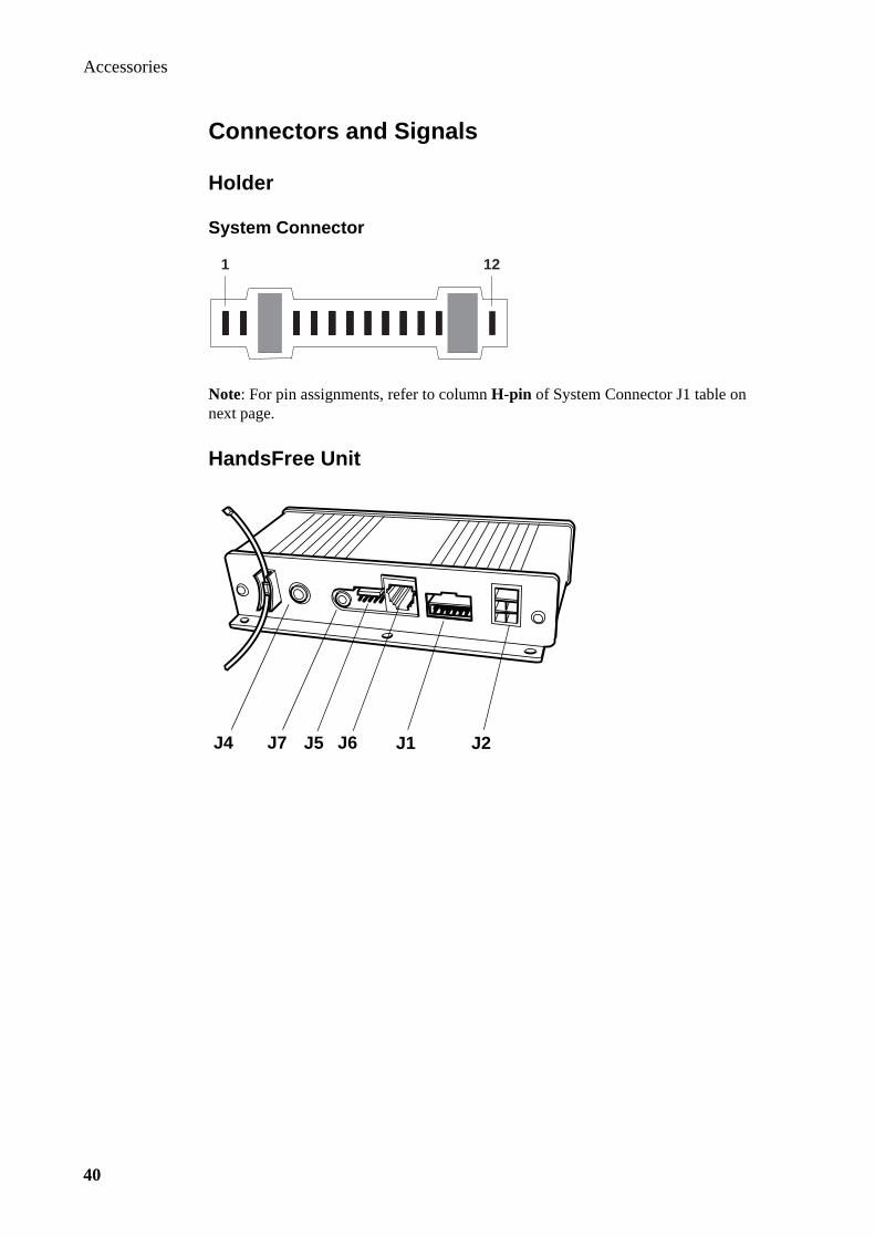
Accessories
40
Connectors and Signals
Holder
System Connector
Note: For pin assignments, refer to column H-pin of System Connector J1 table on next page.
HandsFree Unit
1 12
J4 J7 J6 J1 J2J5

Accessories
41
System Connector J1
J1-pin = HandsFree Unit System Connector J1 pinH-pin = Holder System Connector pin
Power Connector J2
J1-pin H-pin Signal Specification
1 10 DGND Digital ground & DC return
2 12 DCIO DC voltage supply to phone power
3 4 AGND Audio signal ground & 0V reference
4 2 ATMS Audio to mobile station
5 - HOOKSNS Hook sense (connected to cradle, not phone)
6 1 AFMS Audio from mobile station
7 6 MUTE Music Mute
8 3 EXTAUD External analog audio accessory sense
9 5 PORTHF Portable handsfree sense
10 8 VDD Logic reference, status ON
11 9 DFMS Data from mobile station
12 11 DTMS Data to mobile station
1 GND
2 +12VDC
3 MUTEINV
4 n.c.
12
11
2
1
3
4
1
2

Accessories
42
Microphone Connector J4
Microphone connector J4 is femalePicture shows corresponding male
Music Mute Connector J5
Music Mute connector J5 is malePicture shows corresponding female
Data Communication Connector J6
Speaker Connector J7
Speaker connector J7 is femalePicture shows corresponding male
1 +10dB Stick-On microphone
2 0dB Goose-Neck microphone
3 AGND Signal ground
1 LSP- Loudspeaker common
2 DGND Digital ground & DC return
3 LSP+ Loudspeaker signal
4 MUTE Music mute
5 DC12OUT +12VDC output
1 MUTEINV Music Mute (inverted)
2 VDD Logic reference, status ON
3 DC12OUT +12VDC output
4 AFMS (RX) Audio from mobile station
5 D/V Data/voice signal
6 ATMS (TX) Audio to mobile station
7 PORTHF Portable handsfree sense
8 DTMS Data to mobile station
9 DFMS Data from mobile station
10 DGND Digital ground & DC return
1 LSP+ Loudspeaker signal
2 LSP- Loudspeaker common
3 n.c.

HandsFree InstallationEricsson Mobile Phone EF738

HandsFree Installation
2

HandsFree Installation
3
Contents
Vehicle HandsFree Solutions HF7300 & HF7600 _________ 5

HandsFree Installation
4

HandsFree Installation
5
Vehicle HandsFree Solutions HF7300 & HF7600
Music Mute
Data Extension / External Handset via Data Extension Unit

HandsFree Installation
6

Spare PartsEricsson Mobile Phone EF738


To be distributed by the After Sales organization within the Region


Service MessagesEricsson Mobile Phone EF738


To be distributed by the After Sales organization within the Region

Ericsson Mobile Phone
Service Manual
Ericsson Mobile Phone Service Manual
Ericsson Mobile Phone Service Manual
Ericsson Mobile Phone Service Manual
Ericsson Mobile Phone Service Manual
Ericsson Mobile Phone Service Manual
Ericsson Mobile Phone Service Manual