equivalent circuits & reduction (t&r chap 2,3) circuit...
TRANSCRIPT

MAE140 Linear Circuits 23
Equivalent Circuits & Reduction (T&R Chap 2,3)
Circuit EquivalenceTwo circuits are equivalent if they have the same i-v
characteristics at a specified pair of terminals
Terminal = external connection to two nodes = port
Our aim is to simplify analysis replacing complicatedsubcircuits by simpler equivalent circuits
Example
Association of resistors

MAE140 Linear Circuits 24
Equivalent Circuits & Reduction (T&R Chap 2,3)
Resistors in Series
Resistors in Parallel
R2R1
A
B
REQ
A
B
=
R2
R1
A
B
REQ
A
B
=

MAE140 Linear Circuits 25
Example 2-11 (T&R p. 34)
Consider the circuit
Compute equivalent cctsfrom AB and from CD
R3R2
R1
D
CA
B
32
321
3232
11||
RR
RR
RRRRR
CDEQ+
=!!"
#$$%
&+==
'
32
321321 ||
RR
RRRRRRR
ABEQ+
+=+=

MAE140 Linear Circuits 26
Example 2-10 (T&R p. 31) Revisited Can you find iA?
All you need to know is
vA=30V
Answer
iA = -iR =-30/150 = -200 mA;
+
+
+++
- -
-
--30V
100Ω
200Ω300ΩvA v
3
v2
v1i2iA
150Ω++
- -30V vA
iA
=
iR
+
-vR

MAE140 Linear Circuits 27
Equivalent ccts
Equivalent ccts for resistive networks are familiarreductions of parallel and series connectionsThe equivalent cct depends on the port
From an external view the cct could be replaced byits equivalentThe internal cct variables are now unavailable
How would you compute them?
Could we substitute for the cct below?
R3R2
R1
Restof cct 2
Restof cct 1

MAE140 Linear Circuits 28
Equivalent sources
i-v relationships determine equivalence
+-vS
Restof cct
R1
+
-
v
i
+ -vR
11 R
v
R
vi
S+!=
SiR
vi +!=
2
iSRestof cctR2
+
-
v
i
iR
Restof cctR1
+
-
v
i
iR
1R
Sv
+-
Restof cct
R2
+
-
v
i
+ -vR
2RSi

MAE140 Linear Circuits 29
Equivalent Sources (cntd)
i
vSRestof cctR
+
-
v+- Svv =
Sii =iSRestof cct
R1
+
-
v+ -vR
i
i
vSRestof cct
+
-
v+-
iSRestof cct
+
-
v
i

MAE140 Linear Circuits 30
Equivalent Sources (cntd)
i
Restof cct
+
-
v 21 iiiS +=
21 vvvS +=
i
vSRestof cctR
+
-
v+-
iSRestof cct
+
-
v
i
i1 i2
i
v1Restof cct
+
-
v+-
+-v2

MAE140 Linear Circuits 31
Equivalent Sources (cntd)
i
Restof cct
+
-
v
21 iiiS ==
i
vSRestof cctR
+
-
v+-
iSRestof cct
+
-
v
i
i1
i2 i
v1
Restof cct
+
-
v
+- v1 -
+
21 ii =
Only works ifthen
21 vv =
21 vvvS ==
Only works ifthen

MAE140 Linear Circuits 32
Circuit Reduction
For ladder networks
Reduce complexity by successively replacing elements bytheir equivalents
What happens with three elements in series or in parallel?
…
a b c
c a bc b a
a c b
M
+ -i v
They are all equivalentWe can commute elements

MAE140 Linear Circuits 33
T&R Example 2-22 p 49
Find v
Reduce the left end
+_
10Ω20Ω
20Ω 20Ω 10Ω
10Ω
15V
_+ v
10Ω
20Ω 20Ω 10Ω
10Ω
0.75A
_+ v20Ω
10Ω
20Ω 20Ω 20Ω0.75A
_+ v20Ω
10Ω
10Ω 10Ω0.75A
_+ v
10Ω10Ω
10Ω
_+ v_+7.5V Vv 5.2=
MAE140 Linear Circuits 34
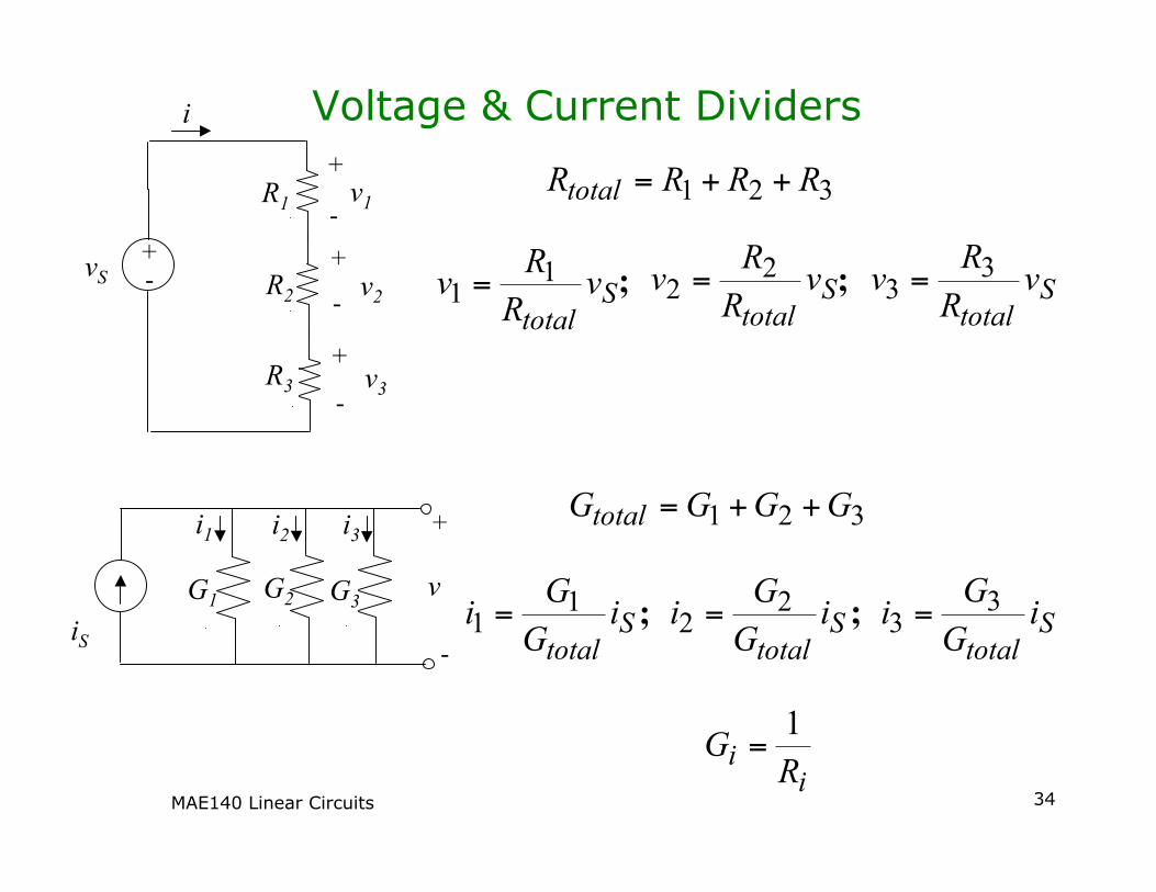
Voltage & Current Dividers
S
total
vR
Rv
11 =
321 RRRRtotal ++=
S
total
vR
Rv
33 =S
total
vR
Rv
22 =; ;
+
+
+
+
-
-
-
-
vS
v1
v2
v3R3
R2
R1
i
iS
i1 i2 i3
G1 G2 G3
+
-
v
321 GGGGtotal ++=
S
total
iG
Gi
11 = S
total
iG
Gi
22 = S
total
iG
Gi
33 =;;
i
iR
G1
=

MAE140 Linear Circuits 35
Voltage Dividers
Often we use a voltage dividerto provide an input voltage toa cct elementWhen would this work?
When the “rest of cct” doesnot draw much currentcompared to R2
Why is this?What is it asking of theequivalent of the rest of cct?
Note that this is a verycommon circuit used to“bias” a transistor to anoperating voltage
++-
-
vS voR2
R1
i
Restof cct

MAE140 Linear Circuits 36
Thévenin and Norton Equivalent Ccts
Thévenin’s TheoremIf the source cct in a two-terminal interface is linear, then
the interface signals v and i do not change when thesource cct is replaced by its Thévenin equivalentNote: nobody says the load must be linear!
Thévenin Equivalent CircuitvT is the open-cct voltage of sourceRT is evaluated from short-cct current
Sourcecct
Loadcct
i+_v
+_vT
RT Loadcct
+_vT
RT voc
+
_
isc
+_vT
RTocT vv =
sc
ocT
T
oc
T
Tsc
i
vR
R
v
R
vi
=
==

MAE140 Linear Circuits 37
Thévenin’s Theorem Proof
Linearity of the Source cct is the key – superpositionHook up a test current source to cct
itest yields voltage vtest
Part I, itest,1=0 but i and v sourcesin Source cct left ON then vtest,1=voc=vT
Part II, itest,2≠0 and sources left OFF in Source cct then vtest,2=-Rtitest,2
By linearity of the Source cct vtest is the sum of these partsfor any choice of itest
This establishes the i-v relationship for any load cct
Sourcecct
i
_vtest itest

MAE140 Linear Circuits 38
Thévenin and Norton Equivalent Ccts
Norton’s TheoremIf the source cct in a two-terminal interface is linear, then
the interface signals v and i do not change when thesource cct is replaced by its Norton equivalent
Norton Equivalent CircuitvT is the open-cct voltage of sourceRT is evaluated from short-cct current
Sourcecct
Loadcct
i+_v
iN RN
Loadcct
voc
+
_
isc
T
T
N
T
scN
R
v
R
v
ii
=
=
=
T
sc
ocN
NscNNoc
R
i
vR
RiRiv
=
=
==
iN RN
iN RN

MAE140 Linear Circuits 39
Example 3-16 p.110 T&R
Find the Thévenin and Norton equivalent ccts of
Find the voltage, current and power if load is 50Ω
Answer: vT=-30V; iN=-417mA; RN=RT=72ΩV=-12.3V; i=-246mA; p=3.03W
+ -
Load
60Ω
30Ω40Ω20Ω
20Ω 50V
+
-
i
v