equatorial precession in the control software of the ka ... · band object observation and...
TRANSCRIPT
Equatorial Precession in the Control Software of the KaBand Object Observation and Monitoring Experiment
Hali J akeman
Kennedy Space Center
Major: Electrical Engineering
KSC FO - Summer 2013
Date: 07 29 2013
https://ntrs.nasa.gov/search.jsp?R=20140002677 2018-09-09T08:26:28+00:00Z

NASA USRP- Internship Final Report
Equatorial Precession in the Control Software of the Ka-Band Object Observation and Monitoring Experiment
Hali L Jakeman • NASA Kennedy Space Center, Merritt Island, FL
The Ka-Band Object Observation and Monitoring, or KaBOOM, project is designed mainly to track and characterize near Earth objects. However, a smaller goal of the project would be to monitor pulsars and study their radio frequency signals for use as a clock in interstellar travel. The use of pulsars and their timing accuracy has been studied for decades, but never in the Ka-band of the radio frequency spectrum. In order to begin the use of KaBOOM for this research, the control systems need to be analyzed to ensure its capability. Flaws in the control documentation leave it unclear as to whether the control software precesses coordinates from the J200 epoch. This experiment will examine the control software of the lntertronic 12m antennas used for the KaBOOM project and detail its capabilities in its "equatorial mode." The antennas will be pointed at 4 choosen points in the sky on several days while probing the virtual azimuth and elevation (horizon coordinate) registers. The input right ascension and declination coordinates will then be converted separately from the control software to horizontal coordinates and compared, thus determining the ability of the control software to precess equatorial coordinates.
Nomenclature d = Number of days since 12000 (including any fraction of a day) A. = Longitude <p = Latitude LST = Local Sidereal time, in degrees UT = Universal Time, in hours 8 = Declination a = Right Ascension
I. Introduction
A lthough the Ka-Band Object Observation and Monitoring project primarily focuses on Near Earth Asteroids, it use of pulsar observations in the Ka band could expand this research subject immensely5
• Pulsars are rotating and magnetized neutron starts that send out pulses within our line of sight of electromagnetic waves, found strongest in the radio frequency'. The time of arrival (ToAs) from the brightest sources can be measured with a precision of about 1 OOns within an hour. Although the atomic clocks found in the rubidium and cesium frequency standards are much more accurate over the short term, pulsar frequency standards decay at a much slower rate2
• They also offer a clock source that is not terrestrial and that is based on macroscopic, instead of microscopic, objects. By using KaBOOM, operating in the Ka-Band, the study of these pulsars can be expanded.
In order to study pulsars, the KaBOOM antennas need to rely on the equatorial coordinate system, in addition to the horizontal system. The tradition coordinate system used by communication antennas is the horizontal system. It uses the elements of azimuth, the angular measurement of an object with reference to true north, and elevation, the angular measurement from the horizon4
. These coordinates change for an object depending on location and time of day. However, astronomical objects are references via equatorial coordinates which include right ascension and declination. In order to imagine this, think of a traditional latitude and longitude coordinate system projected out as a sphere outside of the Earth. This sphere is stationary in reference to the constantly rotating Earth. Right ascension is comparable to latitude. It is an angular measurement of a sidereal object east (positive) or west (negative) of the vernal equinox line. Because of its relationship to sidereal time, it is given in hours instead of degrees. There are 24 hours of RA, each hour corresponding to 15°. Declination is similar to longitude, it is the angular measurement of the distance north or south of the celestial equator (our own equator projected out into space). Depending on location
• Intern, ,NE-E9, Kennedy Space Center
Kennedy Space Center Page I Date 07/25/13

NASA USRP - Internship Final Report
~luual sphere
Figure 1: Celestial Coordinate System (Courtesy of http://www.jtwastronomy.com/(
and time of day, the equatorial coordinates do not change. They move across the sky according to the rotation of the Earth. When the RA of the object is equal to the local sidereal time of your location, it will mean the star will be found on the meridian or the line going directly north to south.
Although RA and Dec do not change over a short amount of time, they are affected by precession: which is the small changes of the rotational axis of Earth3
• Because of this, astronomers agree on standard locations of objects at certain times, called epochs. Most commonly, the epochs are given as J 1950 and 12000. If a star's coordinates is said to be of epoch 12000, it means that the coordinates given correspond to its location on January 1, 2000 at 00:00
GMT, with a similar definition for J 1950. In order to compensate for the precession that occurs from the epoch, coordinates need to be precessed to what is called coordinates of date.
II. Experiment Details
A. Problem
The control software of the 12m Intertronic Antennas allow for KaBOOM to use both coordinate systems. It has the ability to track using either a set of time tagged coordinates in either horizontal or equatorial mode as well as to track a single equatorial mode coordinate as it crosses the sky. In order to do this, the control software continually converts the RA and Dec of an object according to the given location of the antenna and the time. However, there is a large issue with which type of RA and Dec are needed as the input coordinates. In several parts of the operations manual, the coordinates required by the system are noted as "RA and Dec, 12000" (p. 15,33), whereas on several other references of the equatorial coordinates note them as "precessed to date" (p. 42,52). This is a large discrepancy. Although coordinates will only change about 0.073 degrees from 12000, the small beam width (about 0.5 degrees) of the antennas requires the most accurate coordinates available. The value will also increase over the years that KaBOOM will be in use, and will need to be constantly accounted for to ensure long term accuracy of the equatorial pointing.
B. Experiment Procedure
To test the equatorial pointing of the antennas, an experiment will be conducted using the control interface of Antenna 2. It will be commanded to go into equatorial mode on several days to look at 4 arbitrary points in the sky. These points will all have the same RA, which will be associated with the local sidereal time at the time of the experiment. This is to ensure that we have a wide range of movements of the antenna. Although RA is typically given in hours, the control software only receives RA in degrees. We will then look at a Dec of -45°, 0°, 45° and 90°. This will give us a chance to look at points close to the equator as well as high in the sky. These points will all precess differently because of their location in reference to Earth's rotational axis. The most interesting point will be found using a Dec of90°. Using an RA close to LST with this declination will always point the antenna directly at the North Star. This is the point located directly on the rotational axis of Earth and does not move relative to our location. Theoretically, pointing the antenna at this location should give a desired location with an azimuth ofO.OO, and an elevation equal to exactly the longitude of the antenna. For our purposes, this number was input as 28.5093°
Kennedy Space Center Page 2 Date 07/25/13

NASA USRP - Internship Final Report
for Antenna 2. The accuracy of the particular location is not important at the moment, since it is where the antenna thinks its pointing, rather than where is it actually pointing, that is most important for this experiment. This is because the pointing errors have yet to be determined on the KaBOOM antennas.
The experiment will be conducted with and without pointing corrections. Mainly determined by precise measurements of the antenna that have yet to be conducted, these corrections will help ensure future pointing accuracy. At the moment, these correction only account for the deviation of the axis from true vertical, the "axis tilt". Before the experiment, it was unclear how these 2 components will change the output coordinates. The
R/W Register Name
w PowerSwicth
w CorrectionDisable
w DataMode
w RADecDataSource
w RAPosition
w DecPosition
w AZTrackStartTum
w RunControl
R CentraiStatus
w Run Mode
R AzimuthMasterStatus
R ElevationStatus
w RAOffset
w DecOffset
w RADecOffsetMode
Data Registers to Read for Test:
R ElevationVirtuaiAxis
R AzimuthVirtuaiAxis
R SystemCiockms
Address Value
23384 1
23391 1
23399 1
23401 0
23406 lUI#####
23407 ±######
23400 3
23385 1
23383
23386 4
23683
23703
23408 lUI#####
23409 ±######
23402 0/1
23608
23588
23435
Comments
Turns on Power to the Drives
Disable corrections
Equatorial mode
Setpoint as data source (follows one RA/Dec value)
Value of RA: ###.####
Value of Dec ±##.####
Auto (starts tracking with RA and Dec in reach)
Operate
Wait until ByteO, Bit2=0, All drives in operate
BvteO, Bit3 = 0, Clock initialized ByteO, Bit4 = 0, SNTP requests replied to
Track
Wait until all zeros: no errors or trips, axis locked
Wait until all zeros: no errors or trips, axis locked
RA Offset###.#### (optional)
Dec Offset ±##.####(optional)
Disable/Enable Offsets
All Virtual Axis gives the current values of the
position, updated every 4ms.
Note: All read as###.#### or ±##.####
System Oock, read in milliseconds
registers of the control system will allow Figure 2: Sample Program for Equatorial Pointing Test us to enable disable/corrections, set the coordinate input mode, and track a setpoint in the sky. A sample program mode is displayed in Fig. I. For this test, the RA/Dec offsets were not used. The last 3 registers of the experiment detail registers needed to be read in order to complete the proper calculations. We choose the virtual axis registers to show where the antenna hopes to point. This is compared to the actual position of the antenna, which gives where the antenna is physically pointed. The time register is very important for comparison in projected azimuth and elevation calculations completed separately from the control software. There is an error of up to I Oseconds between the reading of the virtual axis registers and the clock register. To help reduce this error, the reading can be taken from a control program provided by lntertronic. However, this will not give ms accuracy and rounds the time up to a tenth of a second.
III. Results
Table 1 and 2 lists the register results of the experiment on July 16, 2013 (JD 2456489.5) and July 23,2013 (JD 2456496.5). These sets of data were taken at an RA of 9h, or 135°. Table I uses the pointing corrections, but table 2 disables these corrections.
Kennedy Space Center Page 3 Date 07/25/13

NASA USRP - Internship Final Report
Inserted Coordinates: RA = 9h Dec = -45d Inserted Coordinates: RA = 9h Dec = -45d Time (ms) VirtuaiAZ Virtual EL Time lms) Virtual AZ Virtual EL 72506231 = 20:08:26.231 195.3194 14.0696 72275900 = 20:04:35.900 199.3488 12.4191 72551302 = 20:09:11.302 195.4615 14.0263 72282900 = 20:04:42.900 199.3681 12.4105 72586358 = 20:09:46.358 195.5062 13.9765 72291900 = 20:04:51.900 199.3929 12.3996
Inserted Coordinates : RA = 9h Dec = Od Inserted Coordinates: RA = 9h Dec = Od Time (ms) Virtual AZ Virtual EL Time (ms) Virtual AZ VirtuaiEL 72729630 = 20:12:9.63 220.5356 54.4872 72166300 = 20:02:46.300 226.5917 51.6817 72749765 = 20:12:29.765 220.6073 54.4141 72191200 = 20:03:11.200 226.72 12 51. 6150 12n0149 = 20:12:50.749 220.m6 54.3852 72205200 = 20:03:25.200 226.7935 51.5775
Inserted Coordinates: RA = 9h Dec = 45d Inserted Coordinates : RA = 9h Dec = 45d Time (ms) Virtual AZ Virtual EL Time lms) VirtuaiAZ Virtual EL 72900190 = 20:15:0.19 318.4946 65.4941 71928400 = 19:58:48.400 315.9184 63.7687 72922722 = 20:15:22.722 318.3559 65.4574 72010300 = 20:00: 10. 300 315.6462 63.5589 72945270 = 20: 15:45.27 318.300 1 65.3786 72082600 = 20:0 I :22.600 315.4113 63.373 1
Inserted Coordinates: RA = 9h Dec =90d Inserted Coordinates: RA = 9h Dec = 90d Time (ms) Virtuai AZ Virtual EL Time (ms) Virtual AZ Virtual EL 73048252= 20: 17:28.252 0.0019 28.5374 72504200 = 20:08:24.200 360.0019 28.5058 73073748 = 20:17:53.748 0.0019 28.5374 72519200 = 20:08:39.200 360.0019 28.5058 73100512 = 20:18:20.512 0.0019 28.5374 72532200 = 20:08:52.200 360.0019 28.5058
Table 1: July 18 Data, Corrections Enabled Table 2: July 22 Data, Corrections Disabled
In order to compare our results with the desired outcome, we needed to convert the right ascension and declination to azimuth and elevation using the time, Julian date, and the location of the antenna. Time is first converted from milliseconds into hours and then used to create a precise Julian date. This is then put into an approximate calculate to determine the local sidereal time. Equation I below describes a reasonable estimate, which is within 0.3 seconds of time for dates within I 00 years of J2000 (stargazing.net). All estimates of LST much occur between 0 and 360°.
LST = 100.46 + 0.985647d +A.+ lSUTt
l!:quation I: Calculating Local Sideral Time
Once LST is calculated, it can be used calculate the hour angle alongside right ascension (a), shown in Equation 2. From here, the hour angle can be used alongside the latitude (q>), and declination (S) to find the azimuth and elevation, shown in Equations 3 and 4
HA = LST -15a
Equation 2: Cnlculatlne hour nn~Ie
cos az = sin ({J sin 8 +cos ({J cos 8 cos HA * Euu11tlun J : Cadculalin~t zmith
sin 8 - sin a2 sin ({J sin el = -------'
cos az cos ({J
Equation 4: Calculatlne Elevation
After these are coordinated for the first set of data, they are then precessed as if they were J2000 coordinates. For this, a calculator create by Robert Ayers§. was used . This calculator has a time resolution of a year. The procedure of conversion is then repeated for the precessed to date coordinated with the same time and date values as the "12000" coordinates.
t http://aa.usno.nayy.mil/fag/docs/GAST.php, http://www.stargazing.net/kepler/altaz.html : http://infohost.nmt.edu/tcc/help/lang/python/examples/sidereal/ims/ AltAz-raDec.html § http://www.robertmartinayers.org/tools/coordinates.html
Kennedy Space Center Page 4 Date 07/25/ 13

NASA USRP- Internship Final Report
Inserted· RA - 9h Dec - -45d Pr.,e<<en I?000·701l1 RA - Qh Om 7~< !),c. = -44° 4~' 14"
Time (ms1 Virtual A7. (0 1 Virtual Fl . (0 ) Inserted A7. (0 ) IIn<erted A7. Error (0 I n<erted EL (0) !Inserted El Error (0
7250623 1 195 3194 14 0696 195.3439 0.0245 13.9722 -0 OQ74
72551302 195.4615 14.0263 195.473_4 0 0 11 Q 1l Q?R? -0 09RI
72586358 195.5062 13.9765 195.5740 0.0678 11 R9l7 -0 OR?R
Inserted· RA = 9h Dec = Od (2000·20111 RA • 9h Om 40s Oec -0° 3' 5"
Time (ms) Virtual AZ (0) Virtual EL {0
\ 1n<PrtPn A7 ro1 11n<PrtPn A7 Frror (0 1 n<PrtPn Fl. (0 ) 11nsertetl Fl Error (0
72729630 220.53.56 . ~4 4R77 770 ~liQO 00114 ~4 4142 -O oqo 7?7497/i~ 7?0 li07l ~4 4141 no liR7~ 0 OR02 54 3860 -0 028 1 72770749 220 7776 54.3852 220.8108 0.0332 54.3357 -0.0495
Inserted: RA - 9h De~ - 4'\tl I Prec.es.en r :woo·?on· RA = 9h Om ~?s !),c. = 44° ~li' 'i~"
Time (ms) Virtual A7 (0 ) Virtual El . (0 ) Inserted A7. (0) I n<erted AZ Error (0 Inserted EL (0
\ Inserted E1 Error {0
72900190 318.4946 65.4941 318.413 1 -0.08 15 li~ 4/i71 -0 0770
72922722 l1R 1'\~Q li~ 4~74 l 1R l 777 -0 0117 li~ 4 1?7 -0 04~?
72945270 11R l001 li~ 17Rii 11R ?1?R -0 0673 65 3571 -0 0215
ln<erted: RA - 9h Oec - 90d I PrPC-P<<Pti (7000·7011. RA - Qh Om 70< l),r - RQ0 ~ '\' lQ"
Time (ms1 Virtual A7 (0 1 Virtual F1. (0 ) 1 nsertetl A7. (0 ) Inserted A7. Error (0 Inserted El. (0) Inserted Fl Error (0
73048252 0 0019 28 5374 0 0000 -0.00 19 28.5087 -0.0287 73073748 0.0019 28.5374 0.0000 ,O..QQ19 ?R ~OR7 -0 O?R7
7310051 2 0.0019 28.5374 0 0000 -0.0019 28.508_7 -0 0287
Table 3a: Results from 7/16/13- Enabled Corrections, Inserted Coordinate Comparison
Inserted: RA = 9h Dec = -45d I Precessed (2000:20131 RA - 9h Om 28s Dec - -44° 48' 14"
Time (ms\ Virtual AZ (0\ Virtual EL (0 1 Prec AZ (0
\ Prec AZ Error (0) Prec EL (0
) Prec EL Error (0)
72506231 195 3194 14 0696 195.3298 0 0104 14. 1845 0.1149
72551302 195.4615 14 .0263 195 4599 -0 0016 14.1406 0 1143
72586358 195.5062 13.9765 195.5610 0.0548 14. 1062 0.1297
Inserted: RA = 9h Dec = Od Precessed (2000:20 13 RA = 9h Om 40s Dec = -0° 3' 5"
Time (ms\ Virtual AZ (0\ Virtual EL (0
\ Prec AZ (0\ Prec AZ Error (0
\ Prec EL (0\ Prec El Error (0
)
72729630 220 5356 54 4872 220.2830 -0.2526 54 4869 -0 0003
72749765 220.6073 54 4141 220.4020 -0.2053 5H39~ 00250
72770749 220.7776 54.3852 220.5257 -0.2519 54.3891 0.0039
Inserted: RA = 9h Dec = 45d (2000:20 11\ RA •9h Om 52s I Dec 44° 56' 55"
Time (ms\ Virtual AZ (0\ Virtual EL (0
\ Prec AZ (0\ Prec AZ Error (0
\ Prec EL (0\ Prec EL Error (0 1
72900 190 318 4946 65 4941 318 5208 0 0262 65.6225 0 1284
72922722 318 3559 65.4574 318.4292 0 0733 65 5677 0 1103
72945270 318.300 1 65 .3786 318.338 1 0.0380 65.5127 0.1341
Inserted' RA = 9h Dec = 90d Precessed (2000·20 13 RA = 9h Om 20s Dec = 89° 55' 39"
. Time(ms) VJJtual AZ (0\ YJJtual El ro\ Prec A7. ( 0
\ Prec A7. Error (0\ Prec EL (0
\ Prec EL Error (0\
73048252 0.0019 28 5374 359.9671 0.0310 28 5752 0.0378 73073748 0.0019 28.5374 359 9670 0.03 11 28.5751 00377
73100512 0.0019 28 .5374 359.9668 0.0313 28.575 1 0.0377
Table 3b: Results from 7/16/13- Enabled Corrections, Precessed Coordinate Comparison
Figures 3a and 3b show the results from the first round of testing on July 16th. On this set of data, corrections were enabled which allowed for the compensation of the small tilt angle of the azimuth axis. It was unclear if the correction would affect the virtual axis, since this is the software's desired position. These graphs lead to ambiguous results. Although the results found in 3a tend to lead towards the antenna not precessing the coordinates, especially within the azimuth, the precessed coordinates have small errors within the elevation. However, because of the large errors in the inserted coordinates, it is clear that the pointing corrections are changing the desired virtual axis.
Kennedy Space Center Page 5 Date 07/25/13

NASA USRP- Internship Final Report
Instead of repeating the experiment in the same exact manner on an different day, the corrections were disabled for the next round of observations. The results are listed in Figure 4a and 4b.
Inserted : RA = 9h Dec = -45d Precessed (2000:20 13 RA = 9h Om 28s Dec = -44° 48' 14"
Time (ms) Virtual AZ(0) Virtual EL (0
) Inserted AZ (0) Inserted AZ Error (0 Inserted EL (0
) Inserted El Error (0
72275900 199.3488 12.4191 199.3478 -0.000955 12.4158 -0.003313
72282900 199.368 1 12.4105 199.3671 -0.000964 12.4073 -0.003230 72291900 199.3929 12.3996 199.3919 -0.000962 12.3963 -0.003295
Inserted: RA = 9h Dec = Od Precessed (2000:20 13 RA = 9h Om 40s Dec = -0° 3' 5"
Time (ms) Virtual AZ (0) Virtual EL(0
) Inserted AZ_i") Inserted AZ Error (0 Inserted EL (0) Inserted E1 Error (0
72166300 226.5917 51.6817 226.5897 -0.001992 51.6784 -0.003272
72 191200 226.7212 51.6150 226.7187 -0.002538 51.6119 -0.003054 72205200 226.7935 51.5775 226.7910 -0.002499 51.5745 -0.002996
Inserted: RA = 9h Dec = 45d Precessed (2000:20 13 RA = 9h Om 52s Dec = 44° 56' 55"
Time (ms) Virtual AZ (0) Virtual EL (0
) Inserted AZ (0) Inserted AZ Error (0 Inserted EL (0
) Inserted El Error (0
71928400 315.9184 63.7687 315.91 10 -0.00741 0 63.7696 0.000917
72010300 315.6462 63.5589 315.6390 -0.007202 63.5599 0.000989 72082600 315.4113 63.3731 315.4038 -0.007453 63.3739 0.000804
Inserted: RA = 9h Dec = 90d Precessed {2000:20 13} RA = 9h Om 20s Dec = 89° 55' 39"
Time (ms) Virtual AZ (0) Virtual EL CO) Inserted AZ_(0
) Inserted AZ Error (0 Inserted EL (0) Inserted E1 Error (0
72504200 360.0019 28.5058 0.0000 -0.001900 28.5087 0.002900
72519200 360.0019 28.5058 0.0000 -0.001900 28.5087 0.002900 72532200 360.0019 28.5058 0.0000 -0.001900 28.5087 0.002900
Figure 4a: Results from 7/23/13- Disabled Corrections, Inserted Coordinate Comparison
Inserted : RA = 9h Dec = -45d Precessed (2000 :20 13 RA = 9h Om 28s Dec = -44° 48' 14"
Time (ms) Virtual AZ (0) Virtual EL (0
) Prec AZ (0) Prec AZ Error (0
) Prec EL (0) Prec EL Error (0
)
72275900 199.3488 12.4191 199.3533 0.004452 12.6285 0.209422
72282900 199.368 1 12.4105 199.3726 0.004542 12.6200 0.209501 72291900 199.3929 12.3996 199.3976 0.004665 12.6090 0.209434
Inserted: RA = 9h Dec = Od Precessed (~000 :20 13 RA = 9h Om 40s Dec = -0° 3' 5"
Time (ms) Virtual AZ (0) Virtual EL (0
) Prec AZ (0) Prec AZ Error CO) Prec ELCO) Prec EL Error (0
)
72166300 226.5917 51.6817 226.3295 -0.262184 51.7450 0.063271
72191200 226.7212 51.6150 226.4590 -0.262158 51.6788 0.063774 72205200 226.7935 51.5775 226.5317 -0.261799 51.6415 0.063992
Inserted: RA = 9h Dec = 45d Precessed (2000:2013) RA = 9h Om 52s Dec = 44° 56' 55"
Time (ms) Virtual AZ (0) Virtual EL (0
) Prec AZ (0) Prec AZ Error (0
) Prec EL (0) Prec EL Error (0
)
71928400 3 15.9 184 63 .7687 315.9856 0.067165 63.9279 0. 159200
72010300 315.6462 63 .5589 315.7100 0.063787 63.7184 0. 159546 72082600 315.411 3 63 .373 1 315.4717 0.060439 63.5327 0. 159591
Inserted: RA = 9h Dec = 90d Precessed (2000:20 13) RA = 9h Om 20s Dec = 89° 55' 39"
Time (ms) Virtual AZ (0) Virtual EL (0
) Prec AZ (0) Prec AZ Error (0
) Prec EL (0) Prec EL Error (0
)
72504200 360.0019 28.5058 359.9611 -0.040786 28.5726 0.066848 72519200 360.0019 28.5058 359.9610 -0.040865 28.5726 0.066811 72532200 360.0019 28.5058 359.9610 -0.040934 28.5726 0.066778
Figure 4b: Results from 7/23/13- Disabled Corrections, Precessed Coordinate Comparison
Figure 4a and 4b prove the need to disable the corrections. This has dramatically changed the results. Unlike the errors found in the enable correction observations, the errors found are consistent with each measurement. In the inserted, non-precessed, results the errors only account to a few thousandths of a degree. With the precessed
Kennedy Space Center Page 6 Date 07/25/13
NASA USRP - Internship Final Report
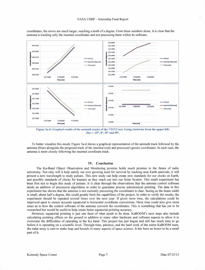
coordinates, the errors are much larger, reaching a tenth of a degree. From these numbers alone, it is clear that the antenna is tracking only the inserted coordinates and not precessing them within its software.
- --226.8000
/ 199.3950 226.7500
12' 7000
- 199.3850 1 22'.6500 i 199.3750
226.6000
-Virt~l - 1265100 - vinuol
1 199.3650 - tmorted IO..oed) 1 22'5000 /
- tn .. rted IO..oedl
- Precened 226.4500 - PrKesied
199.lSSO 276-AOOO
226.3500
t99.).4SO 2263000 72215900 72182900 72291900 72215900 72282900 72291900
n .... lmsl TlMe(mJ)
-------------- -----OJI500
315.9500
315.8500 OOJOO
J 315.7500 ,
- Vinu,t I 0.0100 - VIrtu;al I 315.6500 - lm<rted(O..•ed)
] -0.0100 12115900 72282900 72291900
- tn .. rted ([)Hired)
315.5500 - PrKested -Preces~
315.0500 0.0300
315.3500 11215900 1Wll900 71191900 .o.osoo
llme(ms) llme(m•)
Figure 3a-d: Graphed results of the azimuth tracks of the 7/23/13 test. Going clockwise from the upper left: Dec= -45°, 0°, 45° and 90°.
To better visualize this result, Figure 3a-d shows a graphical representation of the azimuth track followed by the antenna (blue) alongside the proposed track of the inserted (red) and precessed (green) coordinates. In each case, the antenna is more closely following the inserted coordinate track.
IV. Conclusion The Ka-Band Object Observation and Monitoring promise holds much promise to the future of radio
astronomy. Not only will it help satisfy our ever growing need for survival by tracking near Earth asteroids, it will present a new wavelength to study pulsars. This new study can help create new standards for our clocks on Earth, and possibly standards of clocks for humans as they reach out into our Solar System. This small experiment has been first test to begin this study of pulsars. It is clear through the observations that the antenna control software needs an addition of precession algorithms in order to guarantee precise astronomical pointing. The data in this experiment has shown that the antenna is not currently precessing the coordinates to date. Seeing as the beam width is small, about half a degree, this could greatly limit the capabilities of the project. Ln order to verify the results, the experiment should be repeated several times over the next year. If given more time, the calculations could be improved upon to ensure accurate equatorial to horizontal coordinate conversions. More time could also give more clues as to how the control software of the antenna converts the coordinates. This is something that has yet to be researched but would be useful to help create better equatorial pointing accuracy.
However, equatorial pointing is just one facet of what needs to be done. KaBOOM ' s next steps also include calculating pointing offsets on the ground in addition to many other hardware and software aspects to allow it to overcome the difficulties of operating in the Ka band. This project has just begun and still has much time to go before it is operating on a scientific level. Through time, patience, and the hard work of the entire KaBOOM team, the radar array is sure to make leap and bounds in many aspects of space science. It has been an honor to be a small part of it.
Kennedy Space Center Page 7 Date 07125113

NASA USRP- Internship Final Report
References
1Allan, David W., " Millisecond Pulsar Rivals Best Atomic Clock Stability," 4ls1 Annual Frequency Control Symposium. National Bureau of Standards, 1987
2Hobbs, G. eta!, "Development of a pulsar-based timescale," Mon. Not. R. Astron. Soc. , Volume 427, Issue 4, pp. 2780-278 3Hohenkerk, C.Y., Yallop, B.D., Smith, C.A., Sinclair, A.T. , Explanatory Supplement to the Astronomical Almanac,
University Science Books, Mill Valley, CA., 1992, Ch. 3 4Karttunen, H., Kroger, P. , Oja, D., Donner, K. J., Poutanen, M., Fundamental Astronomy, 5th Edition, Springer Berlin
Heidelberg, New York, 2007, Ch. 2 5Martin, G.P, Minear, K. , Geldzahler, B., and Soloff, J. " Large Reflector Uplink Arraying," SpaceOps 2010 Conference,
NASA, 25-30 April2010.
Kennedy Space Center Page 8 Date 07/25/13