epma and tem characterization of intergranular tellurium...
TRANSCRIPT
Corrosion Science xxx (2015) xxx–xxx
Contents lists available at ScienceDirect
Corrosion Science
journal homepage: www.elsevier .com/ locate /corsc i
Letter
EPMA and TEM characterization of intergranular tellurium corrosionof Ni–16Mo–7Cr–4Fe superalloy
http://dx.doi.org/10.1016/j.corsci.2015.04.0170010-938X/� 2015 Elsevier Ltd. All rights reserved.
⇑ Corresponding authors at: 2019 Jia Luo Road, Jiading District, Shanghai Instituteof Applied Physics, Chinese Academy of Sciences, Shanghai 201800, China. Tel.: +8621 39194774; fax: +86 21 39194676.
E-mail addresses: [email protected] (B. Leng), [email protected] (Z. Li),[email protected] (X. Zhou).
Please cite this article in press as: H. Cheng et al., EPMA and TEM characterization of intergranular tellurium corrosion of Ni–16Mo–7Cr–4Fe supCorros. Sci. (2015), http://dx.doi.org/10.1016/j.corsci.2015.04.017
Hongwei Cheng a,b, Bin Leng a,⇑, Kai Chen c, Yanyan Jia a, Jiasheng Dong d, Zhijun Li a,⇑, Xingtai Zhou a,⇑a Thorium Molten Salts Reactor Center, Shanghai Institute of Applied Physics, Chinese Academy of Sciences, Shanghai 201800, PR Chinab University of Chinese Academy of Sciences, Beijing 100049, PR Chinac State Key Laboratory for Mechanical Behavior of Materials, Xi’an Jiaotong University, Xi’an, Shanxi 710049, PR Chinad Institute of Metal Research, Chinese Academy of Sciences, Shenyang 110016, PR China
a r t i c l e i n f o a b s t r a c t
Article history:Received 23 March 2015Accepted 18 April 2015Available online xxxx
Keywords:A. SuperalloyC. Intergranular corrosionC. Reactor conditions
The corrosion behavior of a Ni–16Mo–7Cr–4Fe alloy was investigated in a tellurium (Te) vaporatmosphere at 800 �C. Te was identified via electron probe microanalysis at the grain boundary regionsof the corroded alloy. The morphology, chemical composition, and crystalline structure of those areaswere characterized in a transmission electron microscope. Chromium tellurides were observed at bothgrain boundaries and intergranular carbide–matrix interfaces. Based on the results, the mechanism ofintergranular Te corrosion and its possible correlation with intergranular cracking is discussed.
� 2015 Elsevier Ltd. All rights reserved.
1. Introduction
With the growing demands for safe, reliable, and economicalnuclear energy, developing next generation nuclear reactors isattracting more and more interests and attentions. The molten saltreactor (MSR), which uses molten fluoride salts as coolant and dis-solves fuel in the coolant, is one of the most promising next gener-ation reactors due to its inherent safety, simplified fuel cycle, andhigh power generation efficiency [1,2]. Despite these advantagesof MSRs, the high temperature molten fluoride salts environmentbrings great challenges to the corrosion resistance of MSR struc-tural materials [3,4]. Some nickel-based superalloys possess goodcorrosion resistance against molten salts and small thermal expan-sion coefficients, thus are considered as the key engineering mate-rials for various structural applications in MSRs [5,6]. In the 1950sand 1960s, Oak Ridge National Laboratory (ORNL), USA, designedand developed Alloy N (Hastelloy N), a Ni-based superalloy withmoderate Cr content to reduce the molten fluoride salts corrosionand with high Mo content for solid solution strengthening, specif-ically for the molten salt test reactor. However, the intergranularcracking (IGC) of Hastelloy N has been observed during the opera-tion of the test reactor [7]. Forming on the surface of the alloy,
intergranular cracks can deteriorate the mechanical properties ofthe structural components of the MSR, and further shorten theirlifetime. Therefore, for the development of molten salt energy sys-tems, it is important to understand the mechanism of the IGC [8].Early studies by ORNL indicate that the cracks on the surface ofHastelloy N are mainly related to the inward diffusion of tellurium(Te), a fission product that can be dissolved in the salts and corrodethe structural materials during the operation of the reactor [9,10].According to those studies, Te induced IGC is possibly due to theformation of some brittle grain boundary (GB) compounds,whereas no direct observation of those compounds has been doneto support the mechanism. Since the 1970s when ORNL stopped itsMSR related research, the studies on Te-induced corrosion andcracking of Ni-based alloys have been ceased for decades.Recently, studies in this filed have been revived because of therequest of building next generation MSRs. Annealing experimentsof Te electroplated pure Ni show that Te diffuses into Ni samplesmainly along GBs at and below 900 �C [11]. Computer simulationresults indicate that the segregation of Te at GBs induces GB expan-sion, thus weakens the interfacial Ni–Ni bonds which are essentialto GB cohesion [12,13]. However, these studies do not provide thefull description of the GB after Te corrosion. For instance, the exactmorphology, chemical composition, as well as the structure of thesegregated Te or tellurides are still unrevealed. Moreover, the pre-vious discussion on the mechanism of Te-induced IGC is based onthe simulations of pure Ni metals, without considering the effectsof other alloy elements. This study is aiming at a complete charac-terization of the GBs of a Te corroded Ni-based superalloy. The
eralloy,
2 H. Cheng et al. / Corrosion Science xxx (2015) xxx–xxx
mechanism of Te corrosion and its possible correlation with theIGC of the nickel-based superalloy are discussed.
2. Material and methods
The study was performed on alloy GH3535, a type of Alloy Nwith the nominal composition of Ni–16Mo–7Cr–4Fe (wt.%) thatdesigned and fabricated in China specifically for the future applica-tions of Chinese thorium molten salt reactor (TMSR). The originalalloy bar (18 mm in diameter) was fabricated by casting and hotrolling (870 �C), followed by a solid solution treatment at 1177 �Cfor 0.5 h and water cooling. The chemical composition of the alloywas determined by inductively coupled plasma atomic emissionspectroscopy, and is shown in Table 1. Specimens (1 mm in thick-ness) for tests were cut from the heat-treated bar. After that, thesurfaces of the specimens were mechanically ground using SiCpapers down to 1200 grit and washed with ethanol by ultrasonicbath for 20 min. Then each corrosion specimen was sealed in a vac-uumed quartz tube (18 mm in diameter and 35 cm in length),along with a sufficient amount of Te powders (approximately10 mg/cm2 according to the size of specimen) to produce a Tevapor atmosphere. A comparison specimen was sealed in the same
Table 1Chemical composition of the experimental alloy (wt.%).
Ni Mo Cr Fe Mn Si
Balance 15.9 6.88 4.1 0.49 1.01
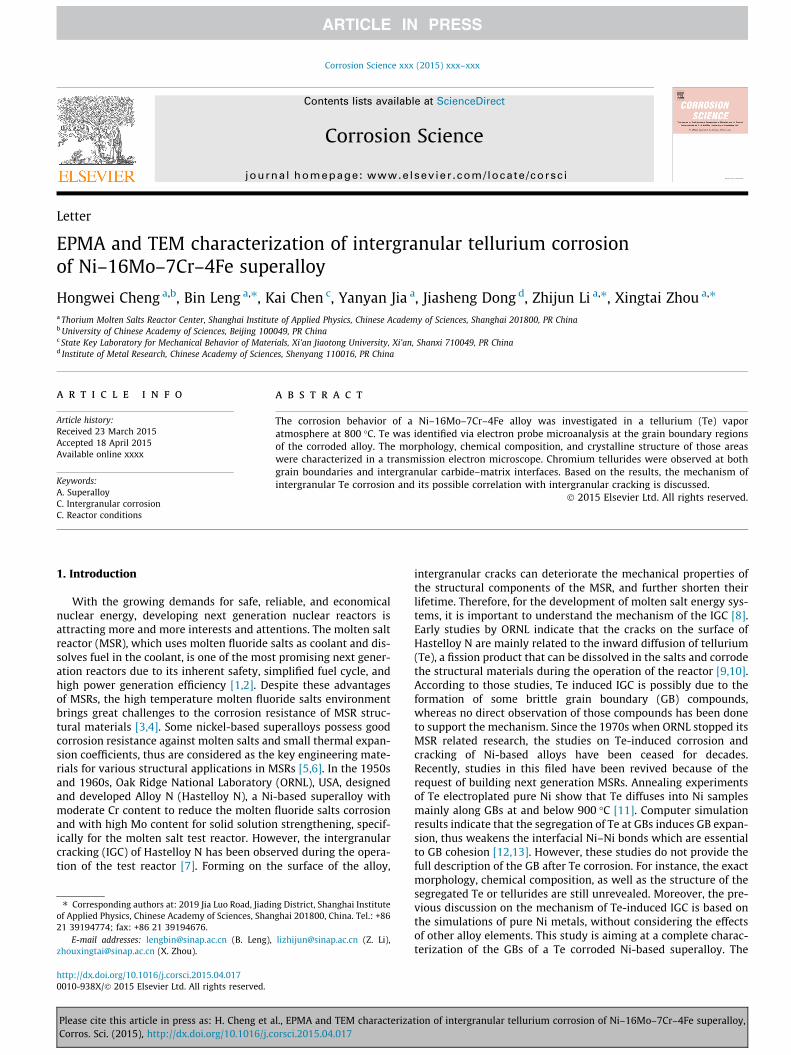
Fig. 1. Secondary electron images showing the microstructures of compariso
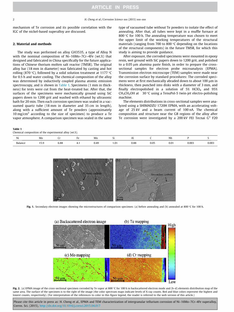
Fig. 2. (a) EPMA image of the cross-sectional specimen corroded by Te vapor at 800 �C fosame area. The surface of the specimen is to the right of the image (the color spectrumlowest counts, respectively). (For interpretation of the references to color in this figure
Please cite this article in press as: H. Cheng et al., EPMA and TEM characterizaCorros. Sci. (2015), http://dx.doi.org/10.1016/j.corsci.2015.04.017
type of vacuumed tube without Te powders to isolate the effect ofannealing. After that, all tubes were kept in a muffle furnace at800 �C for 100 h. The annealing temperature was chosen to meetthe upper limit of the working temperatures of the structuralmaterials (ranging from 700 to 800 �C depending on the locationsof the structural components) in the future TMSR, for which thisstudy is aiming to provide guidance.
After exposure, the corroded specimens were mounted in epoxyresin, wet ground with SiC papers down to 1200 grit, and polishedto a 0.05 lm alumina paste finish, in order to prepare the cross-sectional samples for electron probe microanalysis (EPMA).Transmission electron microscope (TEM) samples were made nearthe corrosion surface by standard procedures: The corroded speci-mens were at first mechanically abraded down to about 100 lm inthickness, then punched into disks with a diameter of 3 mm, andfinally electropolished in a solution of 5% HClO4 and 95%CH3CH2OH at �30 �C using a TenuPol-5 twin-jet electro-polishingmachine.
The elements distributions in cross-sectional samples were ana-lyzed using a SHIMADZU 1720H EPMA, with an accelerating volt-age of 25 kV and a beam current of 100 nA. The chemicalcomposition and structure near the GB regions of the alloy afterTe corrosion were investigated by a 200 kV FEI Tecnai G2 F20
Al C Nb P S
0.88 0.05 0.01 0.003 0.003
n specimen: (a) before annealing and (b) annealed at 800 �C for 100 h.
r 100 h in backscattered electron mode and (b–d) elements distribution map of themaps indicate levels of X-ray counts. Red and blue colors represent the highest andlegend, the reader is referred to the web version of this article.)
tion of intergranular tellurium corrosion of Ni–16Mo–7Cr–4Fe superalloy,

H. Cheng et al. / Corrosion Science xxx (2015) xxx–xxx 3
S-TWIN TEM with an energy dispersion spectrometer (EDS), inboth TEM and scanning transmission electron microscope (STEM)modes.
Fig. 3. EPMA analyses of the Te corroded sample at higher magnification: (a)microstructure (backscattered electron image); (b) EPMA mappings; (c) and (d) EDSspectra of Te-rich phase and Mo carbide, respectively.
3. Results and discussion
The microstructures of the comparison specimen before andafter annealing are shown in Fig. 1. The microstructure of sampleprior to heat treatment is characterized by some large precipitatesthat randomly distributed in the matrix (Fig. 1(a)). A perviousstudy on Hastelloy N has shown that these precipitates are M6Cprimary carbides, where M consists 27.9 wt.% Ni, 3.3 wt.% Si,56.1 wt.% Mo and 4.0 wt.% Cr [14]. After annealing at 800 �C for100 h, the grain size of the alloy and the morphology of the pri-mary carbides remained almost the same, while some fine precip-itates were observed at GBs (Fig. 1(b)). Previous investigations ofthis alloy have identified these fine precipitates as Mo-rich inter-granular secondary carbides, which are also M6C type [15,16].
The cross-section of the corroded specimen after annealing at800 �C for 100 h in the Te vapor atmosphere was examined usingEPMA, and presented in Fig. 2. The element mapping results showthat Te exists at both the reaction layer on the specimen surfaceand the GBs up to about 110 lm beneath the specimen surface(Fig. 2(b)). The reaction layer on the specimen surface consists ofCrTe and Ni3Te2 as identified by X-ray diffraction in the previousstudy [17]. The identification of Te at the GBs indicates that Te dif-fuses into the alloy mainly along GBs at this temperature, same asthe diffusion behavior of Te in pure Ni [11]. Meanwhile, the exten-sive presence of the Mo-rich intergranular secondary carbides wasalso confirmed by the element mapping (Fig. 2(c)). However, fromFig. 2, it is difficult to tell whether Te is combined with Mo in thosecarbides or exists in the form of telluride at GBs. Therefore, EPMAanalyses at higher magnification and more precise S/TEM analyseswere performed and are presented in the next few paragraphs.
The high magnification EPMA analyses of the cross-section ofthe corroded specimen are shown in Fig. 3. The clusters of fine pre-cipitates, which are distributed along GBs (Fig. 3(a)), can be clearlyseen. The EPMA element mapping (Fig. 3(b)) and EDS point analy-ses (Fig. 3(c) and (d)) reveal that these precipitates are eitherMo-rich or Te-rich. As discussed before, the Mo-rich phase is aM6C intergranular secondary carbide. Semi-quantitative analysisof the Te-rich phase (Fig. 3(c)) shows that this phase contains61.88 wt.% Te, 16.05 wt.% Cr, as well as some Ni and Mo.Considering the very small size of the Te-rich particle (about1–3 lm), the detected Ni and Mo signals are possibly due to thesurrounding Ni-rich matrix and the Mo-rich carbides. Therefore,the Te-rich phase is likely to be chromium telluride (CrTe), whichis the most stable telluride at temperatures above 750 �C accordingto the analyses of the surface reaction layers of Te corroded nickel-based alloys [18]. However, the accurate stoichiometry of thistelluride was not determined here due to the uncertainty of EDSelement quantification. All the Cr–tellurides in Fig. 3 are observedat GBs and located adjacent to intergranular carbides, which sug-gests that their formation can be ascribed to the inward diffusionof Te along the GBs and may have some correlations with the inter-granular carbides. To further investigate the structure and compo-sition of the tellurides, the GBs and intergranular carbides in thespecimen after Te corrosion were examined with TEM/STEM.
The STEM high angle annular dark field (HAADF) image of a GBin the alloy after Te corrosion is shown in Fig. 4(a). A lath shapedphase of about 300 nm in width is observed at the GB. As isshown in the EDS mappings (Fig. 4(b)), the enrichment of Crand Te in the lath shaped phase at the GB is observed, whereasthe depletion of Cr is observed in the region surrounding the lath
Please cite this article in press as: H. Cheng et al., EPMA and TEM characterization of intergranular tellurium corrosion of Ni–16Mo–7Cr–4Fe superalloy,Corros. Sci. (2015), http://dx.doi.org/10.1016/j.corsci.2015.04.017
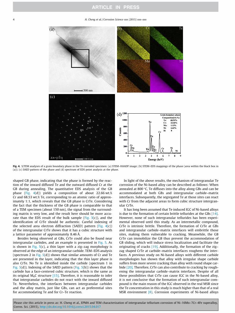
Fig. 4. S/TEM analyses of a grain boundary phase in the Te corroded specimen: (a) STEM–HAADF image; (b) STEM–EDS mappings of the phase (area within the black box in(a)); (c) SAED pattern of the phase and (d) spectrum of EDS point analysis at the phase.
4 H. Cheng et al. / Corrosion Science xxx (2015) xxx–xxx
shaped GB phase, indicating that the phase is formed by the reac-tion of the inward diffused Te and the outward diffused Cr at theGB during annealing. The quantitative EDS analysis of the GBphase (Fig. 4(d)) yields a composition of about 22.66 wt.%Cr and 68.53 wt.% Te, corresponding to an atomic ratio of approx-imately 1:1, which reveals that the GB phase is CrTe. Consideringthe fact that the thickness of the GB phase is comparable to thatof a TEM specimen (about 150 nm), the signal from the surround-ing matrix is very low, and the result here should be more accu-rate than the EDS result of the bulk sample (Fig. 3(c)), and theidentification of CrTe should be authentic. Careful indexing ofthe selected area electron diffraction (SAED) pattern (Fig. 4(c))of the intergranular CrTe shows that it has a cubic structure witha lattice parameter of approximately 8.46 Å.
Besides being observed at GBs, CrTe could also be found nearintergranular carbides, and an example is presented in Fig. 5. Asis shown in Fig. 5(c), a thin layer with a zig–zag morphology isobserved at the edge of an intergranular carbide. TEM–EDS analysis(spectrum 2 in Fig. 5(d)) shows that similar amounts of Cr and Teare presented in the layer, indicating that the thin layer phase isalso CrTe. No Te is identified inside the carbide (spectrum 1 inFig. 5(d)). Indexing of the SAED pattern (Fig. 5(b)) shows that thecarbide has a face-centered cubic structure, which is the same asits original M6C structure [15]. Therefore, it is reasonable to inferthat intergranular carbides do not react with the inward diffusedTe. Nevertheless, the interfaces between intergranular carbidesand the alloy matrix, just like GBs, can act as preferential sitesfor accommodating Te and for Cr–Te reaction.
Please cite this article in press as: H. Cheng et al., EPMA and TEM characterizaCorros. Sci. (2015), http://dx.doi.org/10.1016/j.corsci.2015.04.017
In light of the above results, the mechanism of intergranular Tecorrosion of the Ni-based alloy can be described as follows: Whenannealed at 800 �C, Te diffuses into the alloy along GBs and can beaccommodated at both GBs and intergranular carbide–matrixinterfaces. Subsequently, the segregated Te at those sites can reactwith Cr from the adjacent areas to form cubic structure intergran-ular CrTe.
It has long been assumed that Te induced IGC of Ni-based alloysis due to the formation of certain brittle tellurides at the GBs [14].However, none of such intergranular tellurides has been experi-mental observed until this study. As an intermetallic compound,CrTe is intrinsic brittle. Therefore, the formation of CrTe at GBsand intergranular carbide–matrix interfaces will embrittle thosesites, making them vulnerable to cracking. Meanwhile, the GBCrTe can immobilize the GB thus prevent the accommodation ofGB sliding, which will induce stress localization and facilitate theoriginating of cracks [19]. Additionally, the formation of the zig–zag shaped CrTe at carbide–matrix interfaces roughens the inter-faces. A previous study on Ni-based alloys with different carbidemorphologies has shown that alloy with irregular shape carbidesuffers from more severe cracking than alloy with round shape car-bide [20]. Therefore, CrTe can also contribute to cracking by rough-ening the intergranular carbide–matrix interfaces. Despite of allthese possibilities that CrTe can cause IGC in the Ni-based alloy,it is not conclusive that the formation of such intergranular com-pound is the main reason of the IGC observed in the real MSR sincethe Te concentration in this study is much higher than that of a realMSR environment [8]. Corrosion experiments of Ni-based alloys
tion of intergranular tellurium corrosion of Ni–16Mo–7Cr–4Fe superalloy,

Fig. 5. TEM analyses of an intergranular carbide in the Te corroded specimen: (a) morphology of the carbide; (b) SAED patterns of the carbide (c) high magnification view ofarea within the white box in (a), showing a zig–zag layer formed at edge of the carbide and (d) spectra of EDS point analyses of the carbide and the zig–zag layer, respectively.
H. Cheng et al. / Corrosion Science xxx (2015) xxx–xxx 5
with different compositions in Te-containing molten salts haveshown that the alloys with 7 wt.% and 15 wt.% Cr suffered sameextent of Te-induced IGC while the alloy with 23 wt.% Cr sufferedless, although no explanations are given to the results [14]. It mightbe possible that with the increasing of Cr content in the alloy, aprotective Cr–telluride scale could form on the sample surface toprevent the further diffusion of Te into the alloy. However, theexistence of such protective layer was neither confirmed in thisstudy nor reported before. Therefore, whether Cr facilities the Te-induced IGC or Cr prevents it should depend on the Cr content inthe alloy and the Te content in the environment. Further investiga-tions including corrosion experiments with different Cr and Teconcentrations and mechanical tests are needed to elucidate thispoint.
4. Conclusions
In summary, the distribution of Te in a Ni–16Mo–7Cr–4Fe alloyafter annealing at 800 �C for 100 h in a Te vapor atmosphere hasbeen investigated. Te exists at the GB regions up to about110 lm beneath the sample surface, indicating that Te penetratesinto the alloy by an intergranular diffusion mechanism. The char-acterizations of the morphology, chemical composition and crys-talline structure of those Te containing regions show that a cubicstructure CrTe can form at GBs and the interfaces between inter-granular carbides and the alloy matrix. The results imply that Tecorrosion occurs through the reaction between Te and Cr at theintergranular sites when Te diffuses into the alloy along GBs at
Please cite this article in press as: H. Cheng et al., EPMA and TEM characterizaCorros. Sci. (2015), http://dx.doi.org/10.1016/j.corsci.2015.04.017
elevated temperature. The formation of such telluride can possiblyinduce intergranular cracking of the alloy.
Acknowledgements
This work is supported by the Program of International S&TCooperation, ANSTO-SINAP (Grant No. 2014DFG60230), theNational Natural Science Foundation of China (Grant No.51371188), the Science and Technology Commission of ShanghaiMunicipality (Grant No. 11JC1414900), the Strategic PriorityResearch Program of the Chinese Academy of Sciences (Grant No.XDA02004210), the National Young 1000 Talents Program ofChina, and the Fundamental Research Funds for the CentralUniversities (Grant No. 2015GJHZ03).
References
[1] J. Uhlir, Chemistry and technology of molten salt reactors history andperspectives, J. Nucl. Mater. 360 (2007) 6–11.
[2] D. LeBlanc, Molten salt reactors: a new beginning for an old idea, Nucl. Eng.Des. 240 (2010) 1644–1656.
[3] E. Mohammadi Zahrani, A.M. Alfantazi, Molten salt induced corrosion ofInconel 625 superalloy in PbSO4–Pb3O4–PbCl2–Fe2O3–ZnO environment,Corros. Sci. 65 (2012) 340–359.
[4] Hanliang Zhu, Rohan Holmes, Tracey Hanley, Joel Davis, Ken Short, LyndonEdwards, High-temperature corrosion of helium ion-irradiated Ni-based alloyin fluoride molten salt, Corros. Sci. 91 (2015) 1–6.
[5] R.C. Reed, The Super Alloys: Fundamentals and Applications, CambridgeUniversity Press, New York, 2006.
[6] Sung-ll Baik, M.J. Olszta, S.M. Bruemmer, David N. Seidman, Scr. Mater. (2012)809–812.
tion of intergranular tellurium corrosion of Ni–16Mo–7Cr–4Fe superalloy,

6 H. Cheng et al. / Corrosion Science xxx (2015) xxx–xxx
[7] J.R. Keiser, Status of tellurium-Hastelloy N studies in molten fluoride salts,ORNL/TM-6002, Oak Ridge, TN, USA, 1977, pp. 1–23.
[8] V. Ignatiev, A. Surenkov, Ivan Gnidoy, Alexander Kulakov, Vadim Uglov,Alexander Vasiliev, Mikhail Presniakov, Intergranular tellurium cracking ofnickel-based alloys in molten Li Be Th U/F salt mixture, J. Nucl. Mater. 440(2013) 243–249.
[9] M.W. Rosenthal, R.B. Briggs, Molten-Salt Reactor, ORNL/TM-4832, Oak Ridge,TN, USA, 1973, pp. 1–13.
[10] H.E. McCoy, Intergranular Cracking of Structural Materials Exposed to FuelSalt, ORNL/TM-4782, 1972, pp. 128–136.
[11] Yanyan Jia, Hongwei Cheng, Jie Qiu, Fenfen Han, Yang Zou, Zhijun Li, XingtaiZhou, Hongjie Xu, Effect of temperature on diffusion behavior of Te into nickel,J. Nucl. Mater. 441 (2013) 372–379.
[12] W. Liu, H. Han, Cuilan Ren, Xiujie He, Yanyan Jia, Song Wang, Wei Zhang,Zhijun Li, Xingtai Zhou, Yang Zou, Ping Huai, Hongjie Xu, First-principles studyof intergranular embrittlement induced by Te in the Ni R5 grain boundary,Comput. Mater. Sci. 88 (2014) 22.
[13] M. Všianska, M. Šob, The effect of segregated sp-impurities on grain-boundaryand surface structure, magnetism and embrittlement in nickel, Prog. Mater.Sci. 56 (2011) 817–840.
Please cite this article in press as: H. Cheng et al., EPMA and TEM characterizaCorros. Sci. (2015), http://dx.doi.org/10.1016/j.corsci.2015.04.017
[14] H.E. Mc Coy, Status of materials development for molten salt reactors [R],ORNL/TM-5920, Oak Ridge, TN, USA, 1978.
[15] Zhoufeng Xu, Jiang Li, Jiasheng Dong, Zhijun Li, Xingtai Zhou, The effect ofsilicon on precipitation and decomposition behaviors of M6C carbide in a Ni–Mo–Cr superalloy, J. Alloys Compd. 620 (2015) 197–203.
[16] X.L. Li, S.M. He, X.T. Zhou, Y. Zou, Z.J. Li, A.G. Li, X.H. Yu, Effects of rare earthyttrium on microstructure and properties of Ni–16Mo–7Cr–4Fe nickel-basedsuperalloy, Mater. Charact. 95 (2014) 171–179.
[17] Hongwei Cheng, Fenfen Han, Yanyan Jia, Zhijun Li, Xingtai Zhou, Effects of Teon intergranular embrittlement of a Ni–16Mo–7Cr alloy, J. Nucl. Mater. 461(2015) 122–128.
[18] R.E. Gehlbach, H. Henson, Identification from Tellurium-Structure-Materialinteraction, ORNL/TM-4832, Oak Ridge, TN, USA, 1972, pp. 79–89.
[19] D.A. Woodford, Gas phase embrittlement and time dependent cracking ofnickel based superalloys, Energy Mater. (2006) 59–79.
[20] X.M. Guan, H.Q. Ye, Intergranular embrittlement caused by the precipitation ofM6C carbide containing silicon, J. Mater. Sci. 15 (1980).
tion of intergranular tellurium corrosion of Ni–16Mo–7Cr–4Fe superalloy,