environmentalimpactstatementfor pending planning … · an on-site wastewater treatment plant is...
TRANSCRIPT

ATTACHMENT B.3
Environmental Impact Statement for Pending PlanningApplication
Written Notification to Planning Authority
Drainage Calculation Report
For
insp
ectio
n pur
pose
s only
.
Conse
nt of
copy
right
owne
r req
uired
for a
ny ot
her u
se.
EPA Export 26-07-2013:03:10:44

Kerry Central Recycling Facility Ltd
October 2008MGE0109CR0002
Drainage Calculations
For in
spec
tion p
urpo
ses o
nly.
Conse
nt of
copy
right
owne
r req
uired
for a
ny ot
her u
se.
EPA Export 26-07-2013:03:10:44

Kerry Central Recycli gFacility
Drainage Calculati ns
DOCUME TCO TRO SHE T
Client Kerry Central Recycling Facility Ltd.
Project Title Kerry Central Recycling Facility
Document Title Drainage Calculations
Document No. MGE0109RPOO09
DCS TOC Text List of Tables List of Figures No. ofThis Document AppendicesComprises
1 1 6 1 6-
Rev. Status Author(s) Reviewed By Approved By Office of Origin Issue Date~
F01 Final Issue ~.'~~lja9.9JIn ~~~I ~~en Galway Oct 6th
2008y f.-/
Consulting Engineers
For
insp
ectio
n pur
pose
s only
.
Conse
nt of
copy
right
owne
r req
uired
for a
ny ot
her u
se.
EPA Export 26-07-2013:03:10:44

Kerry Central Recycling Facility Drainage Calculations
MGE0109RP0009 i Rev F01
TABLE OF CONTENTS
1 FOUL SEWER DESIGN PROCEDURE..................................................................................... 1 1.1 DESIGN PARAMETERS...................................................................................................... 1 1.2 PIPE & MANHOLE NUMBERING.......................................................................................... 2 1.3 FOUL LOADINGS .............................................................................................................. 2 1.4 WASTEWATER TREATMENT PLANT.................................................................................... 2
2 STORM SEWER DESIGN PROCEDURE ................................................................................. 3 2.1 SITE INVESTIGATION ........................................................................................................ 3 2.2 STORM SEWER DESIGN ................................................................................................... 3 2.3 DESIGN PARAMETERS...................................................................................................... 3 2.4 PIPE AND MANHOLE NUMBERING ..................................................................................... 4 2.5 HYDROCARBON INTERCEPTOR.......................................................................................... 4
2.5.1 Hydrocarbon Interceptor No. 1 ......................................................................... 5 2.5.2 Hydrocarbon Interceptor No. 2 ......................................................................... 5
3 ATTENUATION SYSTEM DESIGN........................................................................................... 6
APPENDICES
APPENDIX A SITE CHARACTERISATION FORM
APPENDIX B FOUL SEWER CALCULATIONS
APPENDIX C BISON PRELIMINARY PROPOSAL FOR WASTEWATER TREATMENT PLANT
APPENDIX D STORM SEWER CALCULATIONS
APPENDIX E BYPASS SEPARATOR SPECIFICATION SHEET
APPENDIX F ATTENUATION REQUIREMENTS
TABLES
TABLE 1 FOUL LOADINGS
For
insp
ectio
n pur
pose
s only
.
Conse
nt of
copy
right
owne
r req
uired
for a
ny ot
her u
se.
EPA Export 26-07-2013:03:10:44

Kerry Central Recycling Facility Drainage Calculations
MGE0109RP0009 1 Rev F01
1 FOUL SEWER DESIGN PROCEDURE
It is proposed to treat the foul flow from the development in a wastewater treatment system and to discharge the flow to groundwater through a raised bed soil polishing filter as shown on Drawing No. DR0001/01. Details of on-site test results showing the suitability of the site for the discharge of foul flows to groundwater are shown on the Site Characterisation Form in Appendix A.
The proposed foul sewer system shown on Drawing No. DR0001/01 was designed using the Foul Module of MicroDrainage WinDes and complies with the specifications set out in the “Recommendations for Site Development Works for Housing Areas” as issued by the Department of the Environment, Heritage and Local Government.
The outputs from the program are located in Appendix B and include the following:
- Network Design Table
- Network Results Table
- Pipeline Schedules
- Manhole Schedules
Longitudinal Sections are shown on Drawing No. DR0002/05.
1.1 DESIGN PARAMETERS
The following parameters were used for the basis of design in the WinDes Foul Module.
Parameters Values Reference
Flow Rates Non-residential buildings
Peak Flow 6 x Dry Weather Flow (DWF) Site Development Works 1998
Min Velocity 0.76m/s Site Development Works 1998
Pipe Roughness 1.50 (Colebrook/White)
Pipe Cover 1.2 minimum roads and other trafficked areas
0.9m minimum in open spaces and footpaths not adjacent to
roadways
Site Development Works 1998
As per EPA Wastewater Treatment Manual
For
insp
ectio
n pur
pose
s only
.
Conse
nt of
copy
right
owne
r req
uired
for a
ny ot
her u
se.
EPA Export 26-07-2013:03:10:44

Kerry Central Recycling Facility Drainage Calculations
MGE0109RP0009 2 Rev F01
1.2 PIPE & MANHOLE NUMBERING
The pipe numbers define the structure of the network. The first pipe at the head of a system on the main line is numbered 1.000, the second 1.001, the third 1.002 as so on. Likewise the first pipe in a branch line is numbered 2.000 and the second 2.001. Other branches follow suit, 3.000, 4.000 etc. The manhole numbers are shown as F1, F2, F3, etc. – see Drawing No. DR0001/01.
1.3 FOUL LOADINGS
The foul loadings that were used in modelling of the foul network are shown in Table 1.
Table 1: Foul Loadings
Foul System Users Number
of Persons
Flow (L/p/d)
Flow (L/d)
BOD (g/p/d)
BOD (g/d)
Office & Yard Staff 50 60* 3000 30 1500 Drivers 15 30** 450 15 225 Totals 4060 1725
* Table 3 – EPA Wastewater Treatment Manuals, Office and/or factory with canteen ** Foul Loading due to drivers assumed to be 50% of that from office and/or factory with canteen
1.4 WASTEWATER TREATMENT PLANT
An on-site wastewater treatment plant is proposed to treat the foul effluent. The treatment plant will be located as shown on Drawing No. DR0001/01. The proposed treatment plant will be provided with chemical dosing facilities to reduce the phosphorus levels in the treated effluent to <0.5mg/l (Orthophosphate). This will have a minimal effect on the phosphorus levels in the stream of approximately 0.0007mg/l. Refer to Chapter 5 and Chapter 6, surface water and ecological assessment in the EIS, for further assessment on the potential impacts on water quality. Details of the proposed wastewater treatment plant are shown in Appendix C.
For
insp
ectio
n pur
pose
s only
.
Conse
nt of
copy
right
owne
r req
uired
for a
ny ot
her u
se.
EPA Export 26-07-2013:03:10:44

Kerry Central Recycling Facility Drainage Calculations
MGE0109RP0009 3 Rev F01
2 STORM SEWER DESIGN PROCEDURE
2.1 SITE INVESTIGATION
Trial holes were dug on 5th May 2008 in order to determine the existing soil infiltration rate and the soil suitability for a soakaway pit. The location of the trial holes, (ST-01 and ST-02) is shown on Drawing No. DR0001/01.
At the time both holes contained groundwater, therefore a BRE Soakaway Test could not be carried out and the site was deemed unsuitable for the location of a soakaway pit. It is therefore proposed to discharge surface water run-off from the site via an attenuation pond to an existing drainage ditch / stream located at the south west end of the site.
2.2 STORM SEWER DESIGN
The storm sewer system was designed using the MicroDrainage WinDes Storm Module. This system uses the Modified Rational Method of storm flow modelling. This design procedure complies with the specifications set out in the “Recommendations for Site Development Works for Housing Areas” as issued by the Department of the Environment, Heritage and Local Government.
The proposed storm sewer system is shown on Drawing No. DR0001/01. The system incorporates both filter and carrier pipe. The filter pipe will be used as part of the road drainage system, with the carrier pipe used to drain other hard surface areas. Calculations for the storm sewers are shown in Appendix D.
The outputs from the MicroDrainage WinDes Storm Module program include the following:
- Network Design Table
- Network Results Table
- Manhole Schedules
- Pipeline Schedules
Longitudinal Sections are shown on Drawing No. DR0002/01, 02, 03 and 04.
2.3 DESIGN PARAMETERS
The following parameters were used for the basis of design in the WinDes Storm Module.
Parameters Values Reference
Return Period 1 Year Wallingford Procedure
M5-60 15.3 Wallingford Procedure
For
insp
ectio
n pur
pose
s only
.
Conse
nt of
copy
right
owne
r req
uired
for a
ny ot
her u
se.
EPA Export 26-07-2013:03:10:44

Kerry Central Recycling Facility Drainage Calculations
MGE0109RP0009 4 Rev F01
Ration ‘R’ 0.24 Wallingford Procedure
Max Rainfall 50mm/hr Wallingford Procedure
Global Time Entry 4 minutes Wallingford Procedure
Minimum Velocity 0.76m/s Site Development Works 1998
Run-Off Co-efficient Roof = 0.95
Road and Other Hard Surface Areas = 0.8
BS 8005 (Colebrook/White)
Pipe Roughness 0.6 – Carrier Pipe
1.5 – Filter Pipe Colebrook/White
Pipe Cover
1.2 minimum without concrete encasement
0.75 minimum with concrete encasement
Site Development Works 1998
2.4 PIPE AND MANHOLE NUMBERING
The pipe numbers define the structure of the network. The first pipe at the head of a system on the main line is numbered 1.000, the second 1.001, the third 1.002 as so on. Likewise the first pipe in a branch line is numbered 2.000, the second 2.001 and so on. Other branches follow suit, 3.000, 4.000 etc. The Manhole Numbers are shown as S1, S2, S3. etc. – see Drawing No. DR0001/01.
2.5 HYDROCARBON INTERCEPTOR
In accordance with the requirements of BS EN 858, 4.1 (b) ‘(run-off) from impervious areas, e.g. car parks, roads, factory yards areas;’ the size of the separator will depend on the design, rainfall intensity and the catchment area draining to the separator.
The maximum rainwater flow rate Qr in l/s shall be calculated using the equation below in accordance with EN 752-4:
Qr = Ψ.i.A where
• I is the rainfall intensity, in l/s.ha
• A is the area receiving rainfall, measured horizontally, in ha;
• Ψ is a dimensionless coefficient (usually taken as one)
Pollution prevention guidelines (PPG 3) uses a rainfall intensity equal to 65mm/hr which corresponds to the following formula for a bypass separator:
NSB = 0.0018 x A
For
insp
ectio
n pur
pose
s only
.
Conse
nt of
copy
right
owne
r req
uired
for a
ny ot
her u
se.
EPA Export 26-07-2013:03:10:45

Kerry Central Recycling Facility Drainage Calculations
MGE0109RP0009 5 Rev F01
where
• NSB: Nominal Size of Bypass separator
• A: Catchment Area in m2
2.5.1 Hydrocarbon Interceptor No. 1
In this case, the area draining to the bypass separator is approximately 38,600m2 which includes all road/paved areas within the site, resulting in the following:
NSB = 0.0018 x 38,600m2 = 69.5 l/s
As per the Specification sheet for “Klargester” Bypass Separator included in Appendix E, the appropriate unit is the NSBD72, as highlighted. This unit is capable of handling a peak flow rate of 720_l/s as shown. Surface water calculations provided in the Appendix D show a maximum flow rate of 262 l/s which is significantly lower than the capacity of the unit.
2.5.2 Hydrocarbon Interceptor No. 2
In this case, the area draining to the bypass separator is approximately 2,600m2, resulting in the following:
NSB = 0.0018 x 2,600m2 = 4.7 l/s
As per the Specification sheet for “Klargester” Bypass Separator included in Appendix E, the appropriate unit is the NSBD6, as highlighted. This unit is capable of handling a peak flow rate of 60_l/s as shown. This is significantly higher than the actual flow rate the unit will be required to handle.
For in
spec
tion p
urpo
ses o
nly.
Conse
nt of
copy
right
owne
r req
uired
for a
ny ot
her u
se.
EPA Export 26-07-2013:03:10:45

Kerry Central Recycling Facility Drainage Calculations
MGE0109RP0009 6 Rev F01
3 ATTENUATION SYSTEM DESIGN
Attenuation of storm water on-site will be provided by means of an Attenuation Pond. This Attenuation Pond was designed using the following parameters:
(i) Return Period of 30 Years
(ii) Storm duration of 1 minute to 48 hours
(iii) M5-60 = 15.8
(iv) Ratio “R” = 0.3
(v) Coefficient of Runoff from Roofs = 0.95
(vi) Coefficient of Runoff from Road and Other Trafficked Areas = 0.8
The location of the Attenuation Pond is shown on Drawing No. DR0001/01. Details and schematic arrangement for the Attenuation Pond are shown on Drawing No. DR0004/01.
An attenuation pond with a capacity of 600m3 is required.
Calculations for the storage capacity requirements are included in Appendix F.
For
insp
ectio
n pur
pose
s only
.
Conse
nt of
copy
right
owne
r req
uired
for a
ny ot
her u
se.
EPA Export 26-07-2013:03:10:45

APPENDIX A
Site Characterisation Form
For
insp
ectio
n pur
pose
s only
.
Conse
nt of
copy
right
owne
r req
uired
for a
ny ot
her u
se.
EPA Export 26-07-2013:03:10:45

SITE CHARACTERISATION FORM
r f ). rom pi anmng app lea IOn
NAME & ADDRESS OFKerry Central Recycling Facility Ltd.
APPLICANT: ScartlCaherdean,Killarney,Co. Kerry.
SITE LOCATION ANDScartlCaherdean,
TOWNLAND: Killarney,
Co. Kerry.
brian.bruton@TELEPHONE 06432458 FAX NO: 06438661 E-MAIL: kwd.ieNO:
MAXIMUM65 staff@
NO. OF NO. OFNO. OF
6OLlp/dDOUBLE - SINGLE -
RESIDENTS:32 visitors @
BEDROOMS: BEDROOMS:5L1p/d
mains private well/borehole group well/boreholePROPOSED WATER SUPPLY: ~(tick as appropriate)
1 0 GENERAL DETAILS (F
2.0 DESK STUDYSOIL Till Other AQUIFER Regionally Locally PoorTYPE derived (specify) CATEGORY Important Important
chiefly
~fromNamurinRocks
VULNERABILITY Extreme High Moderate Low High to UnknownInterim GSI LowGuidelines and site
~information
BEDROCK Namurian Name of Public/Group Scheme Water
Undiffer- Supply within 1 km Noneentiated
IIs there a GSI Groundwater Source SI SOGroundwater Protection Area None NoneProtection Scheme?
y Protection RI
(Y/N): Response:.
Presence of significant sites (archaeological, natural & N/Ahistorical):
Past experience in the area: N/AComments:(integrate the information above in order to comment on: the potential suitability ofthe site, potentialtargets at risk, and/or any potential site restrictions).From the above we can infer that percolation in the area would be acceptable. However, cautionwould have to be taken due to the under lying aquifer quality and usage and extreme vulnerabilityof the area.
NOTE: Only existing information available at the desk study stage should be used in this section
For
insp
ectio
n pur
pose
s only
.
Conse
nt of
copy
right
owne
r req
uired
for a
ny ot
her u
se.
EPA Export 26-07-2013:03:10:45

3.0 ON-SITE ASSESSMENT
3.1 Visual Assessment
N22 runs adjacent STEEP SHALLOW RELATIVELYI LANDSCAPE the eastern SLOPE: (>1 :5) (1 :5-1 :20) FLAT
POSITION: boundary of the «1:20)site.
,j
SURFACE FEATURES (Distance to features should be noted in metres)
HOUSES: None on proposed site
SITE BOUNDARIES: North - Factory & Agricultural Land East -N22 and Drainage Ditch
South - Agricultural Land West - Drainage Ditch
ROADS: N22 to East of site
EXISTING LAND USE: Greenfield site with conifer plantation
OUTCROPS (ROCK AND/OR None on siteSUBSOIL):
SURFACE WATER PONDING: None on site
LAKES: None on site
BEACHES/SHELLFISHNone on site
AREAS/WETLANDS:
KARSTFEATURES: None on site
WATERCOURSE/STREAM*: None on site
DRAINAGE DITCHES*:Running along the western and eastern boundary of the site. Internaldrainage ditches will be captured in the internal drainage system.
WELLS*: None on site
SPRINGS*: None on site
VEGETATION INDICATORS: Grass and rushes in area of proposed percolation area
GROUND CONDITION: Soft and boggy
COMMENTS:(Integrate the iriformation above in order to comment on: the potential suitability ofthe site, potential targetsat risk, the suitability ofthe site to treat the wastewater and the location ofthe proposed system within thesite).
Water table possibly high on site. Foul water treatment on-site could cause risk to groundwater andsurface water.
* note water level
For
insp
ectio
n pur
pose
s only
.
Conse
nt of
copy
right
owne
r req
uired
for a
ny ot
her u
se.
EPA Export 26-07-2013:03:10:45

3.2 Trial Hole No.!Trial Hole should be a minimum of2.1 m deep (3m where have re ionally important aquifers)Depth of trial Date and Date and timehole (m): l.8m time of 05/05/08 of 06/05/08
excavation: I examination:Depth from ground surface to bedrock (m)(if present): Not encounteredDepth from ground surface to water table (m)(if present): lAm
Soil/Subsoil Texture & Soil Density/ Colour PreferentialClassification** Structure
Compactness ***tlowpaths
0.1 ID
0.2 ID Peat Blocky Compact Dark Grass Rootlets0.3 m Brown
0.4 m0.5 m0.6 m0.7m
0.8 m0.9 m1.0 m1.1 m Blue Grey Clay with Gravel Structureless Soft Blue None
1.2 m Massive
1.3 m1.4 m ...~.IJ~ .1.5 m
....................................................... ......................... ............................................
1.6 m1.7 m1.8 m
rsmdl rn.fJ in\RIril1.9 m -~
2.0m See next page for cross section oftrial hole
2.1 m
2.2 m
2.3 m
2.4 m
2.5m
Other informationDepth Rock type Plasticity 3 samples to be tested for Likely
of 1.4 (if present): N/A and each horizon and results T >20water dilatancy should be entered above for value:
ingress: results: each horizonEVALUAnON: Ground suitable for discharge subject to P Test results.
** See Appendix E for BS 5930 classIficatIOn*** All signs of moUling should be recorded
Note: Depth of percolation test holes should be indicated on diagram above.
For
insp
ectio
n pur
pose
s only
.
Conse
nt of
copy
right
owne
r req
uired
for a
ny ot
her u
se.
EPA Export 26-07-2013:03:10:45

BlueGreyClaywithGravel
WaterTable
Trial Hole No.l - Cross Section
For
insp
ectio
n pur
pose
s only
.
Conse
nt of
copy
right
owne
r req
uired
for a
ny ot
her u
se.
EPA Export 26-07-2013:03:10:45

3.3 (b) Percolation ("P") Test @ Ground Level, Trial Hole No. 1
Percolation Test Hole 1 2
Depth of hole from ground surface (mm) 400 400
Dimensions of hole [length x breadth (mm») 300x300 300x300
Each hole must be pre-soaked twice before the test is carried out (from 10.00 am to 5.00 pm and from5.00 pm to next morning)
Date of test06/05/08 06/05/08
Date pre-soaking started05/05/08 05/05/08
Time filled to 400 mm 10:27 10:32
Time water level at 300 mm 11:01 11:10
Percolation I 2Test Hole
No.
Fill no. Start Time Finish Time ~p (min) Start Time Finish Time ~p (m in)(at 300 mm) (at 200 mm) (at 300 mm) .(at 200 mm)
I 11:01 11:39 38 11: 10 11:55 45
2 11 :43 12:36 53 11:57 12:50 53
3 12:38 14:42 124 12:50 14:58 128
72 75Average ~p Average~p
Average~p/4 = [Hole No.I) ..ll..... (PI) Average ~p/4 = [Hole No.21-12.- (pz)
P value* = (PI + pz)/2 =~ (min/25 mm)
Result of Test: P = 18.5
COMMENTS: The P value is 18.5, giving an infiltration rate ono LlmZlday as the P value is between5 and 20. This was lower than expected.
• If two very different P test results are obtained and where one of these values fails then a third test should be carriedout to determine the representivity of each of the results
For
insp
ectio
n pur
pose
s only
.
Conse
nt of
copy
right
owne
r req
uired
for a
ny ot
her u
se.
EPA Export 26-07-2013:03:10:45

t t11 .3.2 Trial Hole No. 2f21 d (3 h hT . I H I h Id bna o e s ou ea mInimum 0 m eep mw ere ave rel IOna Iy Impor an aQUI ers
Depth of trial Date and Date and timehole (m): 2m time of 05/05/08 of 06/05/08
I excavation: examination:Depth from ground surface to bedrock (m)(if present): Not encounteredDepth from ground surface to water table (m)(if present): Urn
Soil/Subsoil Texture & Soil Densityl Colour PreferentialClassification** Structure
Compactness ***tlowpaths
0.1 m0.2 m Peat Blocky Compact Dark Grass Rootlets0.3 m Brown
0.4 m0.5 m0.6m0.7 m
0.8 m0.9m1.0 m Blue Grey Clay Structureless Soft Blue None
Massive1.1 m
"'~'1J~'....................................................... ......................... .......................... .................
1.2 m1.3 m1.4 m1.5 m L5IJi]@J @u lQJD@
1.6 m See next page for cross section oftrial hole
1.7 m1.8 m1.9 m
2.0m
2.1 m
2.2 m
2.3 m
2.4 m
2.5m
Other informationDepth Rock type Plasticity Likely
of (if present): and T >20water N/A N/A dilatancy value:
ingress: results:EVALVAnON: Ground will provide adequate treatment subject to P test results.
** See Appendix E for BS 5930 classification*** All signs ofmottling should be recorded
Note: Depth of percolation test holes should be indicated on diagram above.
For
insp
ectio
n pur
pose
s only
.
Conse
nt of
copy
right
owne
r req
uired
for a
ny ot
her u
se.
EPA Export 26-07-2013:03:10:45

WaterTable
Trial Hole 2 - Cross Section
BlueGreyClaywithGravel
For
insp
ectio
n pur
pose
s only
.
Conse
nt of
copy
right
owne
r req
uired
for a
ny ot
her u
se.
EPA Export 26-07-2013:03:10:45

3.3 (b) Percolation ("P") Test @ Ground Level, Trial Hole No. 2
Percolation Test Hole 1 2
Depth of hole from ground surface (mm) 400 400
Dimensions of hole [length x breadth (mm)] 300x300 300x300
Each hole must be pre-soaked twice before the test is carried out (from 10.00 am to 5.00 pm and from5.00 pm to next morning)
Date of test06/05/08 06/05/08
Date pre-soaking started05/05/08 05/05/08
Time filled to 400 mm 10:01 10:03
Time water level at 300 mm 10:43 10:46
Percolation 1 2Test Hole
No.
Fill no. I Start Time Finish Time ~p (min) Start Time Finish Time ~p (min)(at 300 mm) (at 200 mm) (at 300 mm) (at 200 mm)
1 10:43 11:51 68 11:26 12:14 48
2 11 :51 13:06 75 12:15 13:41 86
3 13:08 15:10 122 13:44 16:04 140
88 91Average ~p Average ~p
I
Average~p/4 = IHole No.11 ..11.. (PI) Average ~p/4 = [Hole No.2[...lL (P2)
P value* = (PI + P2)/2 = 22.5 (min/25 mm)
Result of Test: P = 22.5
COMMENTS: The P value is 22.5, giving an infiltration rate of 10 Llm2/day as the P value is between20 and 40. This was lower than expected but is more conservative than the P value obtained at TH-OIand will be used in the sizing of the percolation area.
• If two very different P test results are obtained and where one of these values fails then a third test should be carriedout to determine the representivity of each of the results
For
insp
ectio
n pur
pose
s only
.
Conse
nt of
copy
right
owne
r req
uired
for a
ny ot
her u
se.
EPA Export 26-07-2013:03:10:45

Sketch of site showing measurement to Trial Hole location and Percolation Test Hole locations, wellsand direction of groundwater flow (if known), proposed house (incl. distances from boundaries)adjacent houses, watercourses, significant sites and other relevant features. North point shouldalways be included.
lA copy of the site layout drawing should be used if availablel
Please see Drawing No. DROOOI/OI.
For
insp
ectio
n pur
pose
s only
.
Conse
nt of
copy
right
owne
r req
uired
for a
ny ot
her u
se.
EPA Export 26-07-2013:03:10:45

4.0 CONCLUSION of SITE CHARACTERISATION:(Integrate the information from the desk study and on-site assessment (i. e. visual assessment, trialhole and percolation tests) above and conclude the type ofsystem(s) that is (are) appropriate. Thisinformation is also used to choose the optimum final disposal route ofthe treated wastewater).
ISuitable for (delete as appropriate)****:
(a) septic tank and soil percolation system
(b) septic tank and intermittent filter system and polishing unit; or septic tank and constructed'Netlands and polishing unit
(c) mechanical aeration system and polishing unit
****note: more tllan one option may be suitable for a site and t/lis sllould be recorded
and
SUITl·.BLE / UNSUITABLE (delete as appropriate) for discharge to surface water'
SUITABLE / UNSUITABLE (delete as appropriate) for discharge to groundwater
5.0 RECOMMENDATION:
Propose to install: EPS Bison Wastewater Treatment Plant followed by a raised bed soil filter
and discharge to surface water/groundwater (delete as appropriate)
Conditions (if any) e.g. special works, invert level of trench, site improvement works testingetc ..
Signed: Pl Griffin, RPS Consulting Engineers
Address: Lyrr Building, IDA Business and Technology Park, Mervue, Galway
Qualifications/Experience: Chartered Engineer Date of Report: 12'h Sept,2008
Phone: 091 534100 Fax: 091 534199 e-mail [email protected]
I A discharge of sewage effluent to "waters" (definition includes any or any part of any river, stream, lake,canal, reservoir, aquifer, pond, watercourse or other inland waters, whether natural or artificial) willrequire a licence under the Water Pollution Acts 1977-90
For
insp
ectio
n pur
pose
s only
.
Conse
nt of
copy
right
owne
r req
uired
for a
ny ot
her u
se.
EPA Export 26-07-2013:03:10:45

6.0 TREATMENT SYSTEM DESIGN DETAILSSystem Type? BAF
Proposed I Surface water I GroundwaterDischarge route?
Size of Proposed Primary/Septic Tank Secondary Treatment PercolationTreatment System? (m3
) System Capacity (m3) Area/Polishing filter
6.8 6.8 (State units - m or m2)*
345m2 soil polishingfilter
What Quality Assurance Installation & Commissioning On-going Maintenanceis proposed during the
Installed and commissioned by EPS On-going maintenance by EPSfollowing?
* the calculated percolation area or polishing filter area should be shown on site plan
7.0 REVIEW (by Local Authority)
Site visit D Date:
Inspection of Trial Hole D Date:
Inspection of Percolation Test Holes D Date:
COMMENTS
SIGNED: Date:
For
insp
ectio
n pur
pose
s only
.
Conse
nt of
copy
right
owne
r req
uired
for a
ny ot
her u
se.
EPA Export 26-07-2013:03:10:45

APPENDIX B
Foul Sewer Calculations
For
insp
ectio
n pur
pose
s only
.
Conse
nt of
copy
right
owne
r req
uired
for a
ny ot
her u
se.
EPA Export 26-07-2013:03:10:45

----------------------------------------- PaeT---------=-~_==_~
: Kerry Central ' II
Recycling Facility I !Foul Network I I
! Designed By JO'C _. I '_nu_J Chec;~ed By . _
_.._§y~teIllU"l·1 0.4 . .__ .....___ _
I Date 29108/2008I File MGE01 09WD0009D03.fws
Micro Draina.9~ ~ =-~~~~-=_-:.
FOUL SEWERAGE DESIGN
Global Variables
Pipe Size File C: \WinDes\STANDARD.PIP Manhole Size File C: \WinDes\STANDARD.MHS
Network Design Table
Designed with Level Inverts
Industrial Flow (l/s/ha)Industrial Peak Flow FactorFlow Per Person (l/per/day)Persons per HouseDomestic (l/s/ha)Domestic Peak Flow FactorO'flow Setting (*Foul only)Infiltration %Minimum Backdrop Height (m)
0.000.00
180.001.000.006.00
oo
0.200
Depth from Soffit to G.L. (m)Min Vel. (m/s - Auto Design Only)
Min Slope (l:X - Optimisation)Minimum Outfall Invert {m)
Ground Level at Outfall (m)Outfall Manhole Name
Outfall Manhole Dia/Length {mm)Outfall Manhole Width (mm)
1.2000.761000
0.000107.480
WWTP
g I
Ii
~----.----._--i
I
PN Length Fall Slope Area Hse DWF k HYD DIA(m) (rn) (l :X) (ha) (l/s) (mm) SECT (mm)
1.000 64.31 0.637 100.9 0.000 19 0.0 0.600 0 1501.001 80.76 0.470 171.7 0.000 0 0.0 0.600 0 1501.002 11.40 0.066 171. 7 0.000 0 0.0 0.600 0 150
Network Results Table
PN US/IL E.Area E.DWF E.Hse Infi1. P.Dep P.Vel Vel CAP Flow(m) (ha) {lis) (l/s) (mm) (m/s) (m/s) (l/s) (l/s)
1.000 106.155 0.000 0 19 0 12 0.35 1.00 18 01. 001 105.518 0.000 0 19 0 14 0.29 0.76 13 01.002 105.047 0.000 0 19 0 14 0.29 0.76 13 0
For
insp
ectio
n pur
pose
s only
.
Conse
nt of
copy
right
owne
r req
uired
for a
ny ot
her u
se.
EPA Export 26-07-2013:03:10:45

n~pS::-MCOS~-- ---.------.-.----~_~_~~-- --+I Innishmore Kerry Central; Ballincollig Recycling Facility! Co CorK Foul NetworkiDate 29/08/2008 Designed-By JO'C" ----..------------i File MGE0109WD0009D03Jws I Checked By
~Micro Drainl:!gL . . ~stem1·vt,~1Q~4 ~-~._=:==.:.-==--==.-==-------------------..---Ji
PIPELINE SCHEDULES
Upstream Manhole
PN Hyd Diam MH No. C.Leve1 I.Leve1 Depth MH DIAM. , L*WSect (mm) (m) (m) (m) (mm)
1.000 0 150 F1 109.B30 106.155 3.525 12001.001 0 150 F2 107.B30 105.51B 2.162 12001.002 0 150 F3 107.4BO 105.047 2.283 1200
Downstream Manhole
PNLength Slope MH No. C.Leve1 I.Leve1 Depth MH DIAM. , L*W
(m) (l :X) (m) (m) (m) (mm)
1.000 64.31 100.9 F2 107.830 105.518 2.162 12001.001 80.76 171.7 F3 107.480 105.047 2.283 12001.002 11.40 171. 7 WWTP 107.480 104.981 2.349 0
l-
For
insp
ectio
n pur
pose
s only
.
Conse
nt of
copy
right
owne
r req
uired
for a
ny ot
her u
se.
EPA Export 26-07-2013:03:10:45

D (mm)Pipes In
IL. (m)PND (mm)Pipes Out
IL. (m)PN
M/Hole iDiam. ,L*W
(mm)I
M/HoleDepth
(m)
CoverLevel
(m)
M/HoleNumber
[RPs=iV1cosTtd-- ----------------~--------------:=~~=__==_=_==~=:_=~_----+-,~~====i lnnishmore Kerry CentralI Ballincollig Recycling Facility; Co Cork Foul Network10ate29/0B12008 Designed By JO'C ---- --- -------.--L.file MG~jQ§l.wJ2_Q009D03.f'N~_________ Checked By__________________________ _ _I- MjcrgJ?.r2.i!1.?g_El ~stemtyv·10__'_4. __ --------- ---- ------------------------ -1[ MANHOLE SCHEDULES ,II
II
F1 109.830 I 3.675 1200 1.000 106.155 150
F2 107.830 2.312 1200 1.001 105.518 150 1.000 105.518 150
F3 107.480 2.433 1200 1. 002 105.047 150 1.001 105.047 150
WWTP 107.480 2.499 0 OUTFALL 1.002 104.981 150
-------------- -----------1__ .. ..__~ .-..J
For
insp
ectio
n pur
pose
s only
.
Conse
nt of
copy
right
owne
r req
uired
for a
ny ot
her u
se.
EPA Export 26-07-2013:03:10:45

APPENDIX C
Bison Preliminary Design Proposal for WastewaterTreatment Plant
For
insp
ectio
n pur
pose
s only
.
Conse
nt of
copy
right
owne
r req
uired
for a
ny ot
her u
se.
EPA Export 26-07-2013:03:10:46

PRELIMINARY DESIGN PROPOSAL
FOR
WASTEWATER TREATMENT PLANT CLIENT REPRESENTATIVE RPS DATE 23rd July 2008 REFERENCE QB10160-08
For
insp
ectio
n pur
pose
s only
.
Conse
nt of
copy
right
owne
r req
uired
for a
ny ot
her u
se.
EPA Export 26-07-2013:03:10:46

TABLE OF CONTENTS
1. Introduction
2. Design Parameters EPA Recommended Loading Rates EPA Recommended Set Back Distances Design Basis Design Criteria Design Calculations
3. Scope of Supply
4. Quotation 5. Exclusions 6. Description of Treatment Process
6.1 Primary Treatment 6.2 Secondary Treatment
6.2.1 SAF 6.2.2 SBR 6.2.3 CAS 6.2.4 MBR
6.3 Tertiary Treatment 6.3.1 Self-Cleaning Mechanical Filter 6.3.2 In-Situ Sand Filter 6.3.3 Reed Bed System 6.3.4 Disinfection System
6.4 Nutrient Removal 6.4.1 Nitrification 6.4.2 Denitrification 6.4.3 Phosphate Reduction
6.5 Additional Items 6.5.1 Screening 6.5.2 Grease Removal 6.5.3 Flow Splitting Chamber 6.5.4 Recirculation Chamber 6.5.5 Inlet Pumping Station 6.5.6 Outlet Pumping Station
6.6 Instrumentation 6.7 Operation and Maintenance 6.8 Design of Disposal System
7. Installation Guidelines 8. O&M Manuals
9. Additional Process Description and Design
10. Drawings
For
insp
ectio
n pur
pose
s only
.
Conse
nt of
copy
right
owne
r req
uired
for a
ny ot
her u
se.
EPA Export 26-07-2013:03:10:46

1. INTRODUCTION The following report has been compiled using loading details and Population Equivalency (P.E.) supplied by Earth Science Partnership The design criteria and parameters have been calculated based on the recommended EPA loading rates as outlined in Table 2.1 below. Treatment plant selection has been based on the max loading rates based on 100% occupancy as per Table’s 2.3, 2.4 and 2.5 below. Prior to approval a site investigation and assessment will be required. 2. DESIGN PARAMETERS Table 2.1. EPA Recommended Loading Rates
Situation
Source
Flow litres/day
per person
BOD5 grams/day per person
Office and/or factory without canteen 30 20 Industrial Office and/or factory with canteen Open industrial site e.g. quarry (excluding canteen)
60 40
30 25
Non-residential with cooking on-site 60 30 Non-residential with no canteen 40 20
Schools
Boarding school: (1). Residents (2). Day Staff (includes mid-day meal)
180 60
60 30
Guests 250 75 Guests (no meal) 180 45 Resident staff 180 60 Day Staff 60 30 Conference 40 20
Hotels
Restaurant full meals: (1). Luxury Catering (2). Prepared Catering (3). Snack Bars (4). Function Rooms incl. Buffets (5). Fast Food
25 15 10 10 10
25 15 10 10 10
Residents 200 60 Day Staff 60 30 Bar Drinkers 10 10
Pubs and Clubs
Bar Meals 10 10
For
insp
ectio
n pur
pose
s only
.
Conse
nt of
copy
right
owne
r req
uired
for a
ny ot
her u
se.
EPA Export 26-07-2013:03:10:46
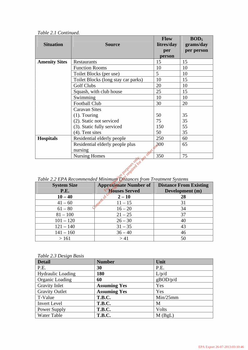
Table 2.1 Continued.
Situation
Source Flow
litres/day per
person
BOD5 grams/day per person
Restaurants 15 15 Function Rooms 10 10 Toilet Blocks (per use) 5 10 Toilet Blocks (long stay car parks) 10 15 Golf Clubs 20 10 Squash, with club house 25 15 Swimming 10 10 Football Club 30 20
Amenity Sites
Caravan Sites (1). Touring (2). Static not serviced (3). Static fully serviced (4). Tent sites
50 75 150 50
35 35 55 35
Residential elderly people 250 60 Residential elderly people plus nursing
300 65 Hospitals
Nursing Homes 350 75 Table 2.2 EPA Recommended Minimum Distances from Treatment Systems
System Size P.E.
Approximate Number of Houses Served
Distance From Existing Development (m)
10 – 40 2 – 10 28 41 – 60 11 – 15 31 61 – 80 16 – 20 34 81 – 100 21 – 25 37 101 – 120 26 – 30 40 121 – 140 31 – 35 43 141 – 160 36 – 40 46
> 161 > 41 50 Table 2.3 Design Basis Detail Number Unit P.E. 30 P.E. Hydraulic Loading 180 L/p/d Organic Loading 60 gBOD/p/d Gravity Inlet Assuming Yes Yes Gravity Outlet Assuming Yes Yes T-Value T.B.C. Min/25mm Invert Level T.B.C. M Power Supply T.B.C. Volts Water Table T.B.C. M (BgL)
For
insp
ectio
n pur
pose
s only
.
Conse
nt of
copy
right
owne
r req
uired
for a
ny ot
her u
se.
EPA Export 26-07-2013:03:10:46

Table 2.4. Design Criteria Parameter Influent Effluent Unit Design Flow 6 6 M3/d Peak Flow 0.75 0.75 M3/hr 3DWF BOD Load 1.8 0.072 Kg/d T.N. - Mg/L T.P - <1 Mg/L Orthophosphates <0.5 S. Solids 30 Mg/L BOD 20 Mg/L Domestic/Commercial Domestic 2.5 DESIGN CALCULATIONS
E.P.S. Design Brief / Basis:
• Organic Loading - 60 g BOD/p/d • Hydraulic Loading - 200 L/p/d
Hydraulic Loading
30 people 30 @ 200 L/p/d = 30 x 200
= 6000 L/d
Organic Loading:
30 people 30 @ 60g/p/d = 30 x 60
= 1800 g/d
Total P.E (As per the Hydraulic Load) = 30 P.E. Total P.E (As per the Organic Load) = 30 P.E.
EPS Ltd. propose 1 No. 30 P.E. Concrete Treatment Plant
For
insp
ectio
n pur
pose
s only
.
Conse
nt of
copy
right
owne
r req
uired
for a
ny ot
her u
se.
EPA Export 26-07-2013:03:10:46

- SCOPE OF SUPPLY
The table below outlines all the main treatment options supplied by EPS. The items applicable to this development have been marked with a ‘Y’.
Treatment System
Y/N
Description
Primary Treatment Primary Settlement Tank See Product Selection Secondary Treatment SAF Plants
- CT - Concrete
Y
SBR CAS MBR Tertiary Treatment Self Cleaning Sand Filter In-situ Sand Filter Reed Bed Disinfection
- UV - EFFG System
- LBX System
Nutrient Removal Nitrification (Ammonia) Denitrification (Anoxic Zone) Phosphate Reduction Y Optional Additional Plant Items Screening Grease Removal Disposal Options Design Flow Splitting Chamber Recirculation Chamber Inlet Pumping Station Outlet Pumping Station Flow Metering Y Optional Remote Monitoring Y Optional Sampling Y Optional Operation and Maintenance Service Contract Operation and Maintenance Contract Y
For
insp
ectio
n pur
pose
s only
.
Conse
nt of
copy
right
owne
r req
uired
for a
ny ot
her u
se.
EPA Export 26-07-2013:03:10:46

Treatment System
Y/N
Description
SAF PLANTS (grp) Standard Range CT 25 CT 35 CT 50 CT 75 CT 100 CT 125 CT 150 SAF PLANTS (grp) Nitrifying Range CT 35-N CT 50-N CT 75-N CT 100-N M 200 M 250 M 300 M 400 M 500 M 600 AQUAMAX RANGE 30 PE Concrete Y 50 PE Concrete 75 PE Concrete 100 PE Concrete 150 PE Concrete 200 PE Concrete 250 PE Concrete 300 PE Concrete
For
insp
ectio
n pur
pose
s only
.
Conse
nt of
copy
right
owne
r req
uired
for a
ny ot
her u
se.
EPA Export 26-07-2013:03:10:46

Treatment System
Y/N
Description
SBR (Sequencing Batch Reactor) 200 300 400 500 600 700 800 900 1000 CAS 150 200 300 400 Duplex Systems 400 PE upwards MBR 125 250 375 500 750 1000 1500 2000 2500
For
insp
ectio
n pur
pose
s only
.
Conse
nt of
copy
right
owne
r req
uired
for a
ny ot
her u
se.
EPA Export 26-07-2013:03:10:46

5. EXCLUSIONS AND CLIENT RESPONSIBILITIES It shall be the responsibility of the client to provide the following:
• Provision of power to EPS Control Panel • Any excavation or backfilling • Any additional civil works or pumping as may be required for
sites with water table issues. • Site clearance and reinstatement • Provision of ducting • Provision of concrete hard standing areas as required • Connection of inlet and outlet sewer lines • Provision of seed sludge where applicable for plant start-up • Provision and installation of and maintenance of a suitable
grease trap if not otherwise included in EPS supply. • Provision of chemicals as required for commissioning and set-
up • Access to treatment plant site for a 40ft articulated truck to
allow for placement of tanks. Any necessary crane hire is the clients responsibility unless otherwise agreed by EPS.
• Provision of and construction of disposal systems. • Provision of pipework from pump stations to disposal systems. • All site security and fencing
For
insp
ectio
n pur
pose
s only
.
Conse
nt of
copy
right
owne
r req
uired
for a
ny ot
her u
se.
EPA Export 26-07-2013:03:10:46

6. TREATMENT OPTIONS 6.1 PRIMARY TREATMENT Our range of primary settlement tanks (PST) are available in both concrete and glass reinforced plastic (grp). We offer single stage, two stage and three stage settlement options. All primary settlement tanks are designed to reduce the gross and suspended solids loading prior to secondary treatment. Sludge storage requirements are also included in PST design. Storage periods will vary depending on the option provided but as a general rule all primary settlement tanks should be desludged every 3 months at a minimum. A primary settlement tank requires little maintenance, as there are no moving parts or electrical parts associated. Desludging and silt removal where applicable is the main requirement for primary settlement tanks. 6.2 SECONDARY TREATMENT 6.2.1 SAF PLANTS A submerged aerated filter normally consists of a primary settlement tank, an aerated submerged biofilm reactor and a secondary settlement tank. This type of system is a well-developed technology and is regularly used for small communities. 6.2.2 CT RANGE Incoming sewage is separated and stored in the first section of the primary settlement tank, allowing only settled liquor to pass forward for biological treatment. The biological treatment stage comprises of two separate zones in series, both using submerged aerated filter technology and a well known jet aeration system – the VENTFLO Inductor. The first biological stage treats the majority of the carbonaceous stage, resulting in a low loading rate for the second stage and a subsequent high overall removal rate. Biomass (humus stage) sloughed from the submerged media is separated in the final humus settlement stage and returned intermittently by pump to the primary stage for co-settlement. 6.2.3 CONCRETE RANGE Incoming sewage is separated and stored in the two stage primary settlement tank(s), allowing only settled liquor to pass forward for biological treatment. The biological treatment tank comprises of select filter media to sustain biological growth and an aeration system comprising of a duty air blower and a diffused aeration system. The treated effluent then passes to a final settlement tank prior to discharge where any humus sludge or suspended solid material settles out. A timer operated sludge return pump returns sludge intermittently to the primary settlement tank for storage.
For
insp
ectio
n pur
pose
s only
.
Conse
nt of
copy
right
owne
r req
uired
for a
ny ot
her u
se.
EPA Export 26-07-2013:03:10:46

6.2.4 SBR – Sequencing Batch Reactor The Sequencing Batch Reactor process is a form of activated sludge treatment in which aeration, settlement and decanting occur in a single tank. SBR’s can operate as a uni-tank or multiple tank set-up. The process employs a five stage cycle which may be repeated a number of times per 24 hour period. The five stages include fill, aerate, settle, decant, rest. The wastewater is pumped into the SBR during the fill stage. The contents are then aerated and mixed prior to a quite settlement phase where all of the biomass and solids settle out. The clear supernatant is then decanted from the system. Following a rest phase the cycle is repeated. Periodically excess sludge is removed from the system during the rest phase and stored prior to removal off-site for treatment and disposal. The SBR process provides good operational flexibility and allows for the option of incorporating nitrification, denitrification and phosphorous removal. It is a simple and reliable system, ideal for the treatment of varying flow and load conditions. This type of system is of particular benefit when treating wastewater from hotels, pubs and restaurants, etc. 6.2.5 CAS PLANT The EPS CAS plant is based on conventional activated sludge technology. Each unit is factory built complete with all necessary equipment necessary for efficient operation. A CAS plant is of steel construction, divided into two major sections – an aeration section and a clarifier. Each unit comprises of an inlet box, aeration header with drop pipes and diffusers, roots type blower including motor, controls, drives and fittings, sludge return and storage. Following aeration the mixed liquor of activated sludge and treated effluent passes forward to the clarifier where conditions are favourable for the separation of settled sludge and the final effluent prior to discharge. All settled solids are returned continuously to the aeration section for further treatment. Periodically excess sludge is wasted from the system to a sludge storage tank prior to removal off-site for treatment and disposal. Nitrification, denitrification and phosphorous removal can also be accommodated with this system.
For
insp
ectio
n pur
pose
s only
.
Conse
nt of
copy
right
owne
r req
uired
for a
ny ot
her u
se.
EPA Export 26-07-2013:03:10:46

6.2.6 MBR – Packaged Membrane Bioreactors MBR technology is a leading edge technology for the treatment of wastewater to a very high standard. Typically a final effluent standard of 5 : 5 : 5, BOD : SS : NH4 is achieved consistently. Background The development of our submerged membrane bioreactor technology was the result of a Japanese Government initiative to produce compact, high quality effluent, treatment plants. Since producing the first pilot plant using MBR technology in 1989 and the first commercial plant in 1991, over 950 plants have been installed worldwide. These treat a wide range of wastewaters, the principal application being sewage and sludge liquors, but also including industrial and food processing wastewater, and grey water recycling for a wide range of re-use purposes. Process Description The process employs simple flat sheet membrane panels housed in stainless steel cases and aerated by a coarse bubble diffuser system. A series of these membranes are submerged within an activated sludge treatment tank. An advantage of this design is that the membrane panels are securely retained and cannot touch or abrade each other, while the cases also act as a flume to ensure effective tank mixing and even distribution of the biomass. The membrane panels are manufactured with an average pore size of 0.4 microns, which in operation becomes covered by a dynamic layer of protein and cellular material. This further enhances the performance effectiveness of the filtration process by providing an effective pore size of less than 0.01 microns, which is in the ultra-filtration range. Our membrane bioreactor treatment produces a high quality disinfected effluent. The raw sewage generally only requires screening (to 3mm) and de-gritting prior to entering the membrane bioreactor tank. The process requires no primary or secondary settlement stages and no additional tertiary treatment or UV stages to achieve quality typically better than 5 : 5 : 5 mg/l BOD : Suspended Solids : Ammonia. The MBR system has a number of inherent advantages. It does not remove the solids by settlement, therefore the biomass can operate at very high levels of mixed liquor suspended solids (MLSS), generally in the order of 12,000-18,000 mg/l, and up to 22,000 mg/l. This high concentration enables a low tank volume and a long sludge age to be utilised, which reduces sludge production and allows a small footprint. The associated viscosity with the suspended solids will affect the cross flow over the membrane surface. It is recommended that in normal operation the MLSS does not routinely go below 10,000 mg/l and that a minimum level of 8,000 mg/l at average flow is recommended. The maximum hydraulic flow determines the required number of membrane units. Each membrane unit may contain up to 400 flat plate membrane panels housed within a rectangular case, together with an integral aeration system in the bottom section of the unit. Treated effluent is removed from the membrane units using gravity head (typically 1 –1.2m).
For
insp
ectio
n pur
pose
s only
.
Conse
nt of
copy
right
owne
r req
uired
for a
ny ot
her u
se.
EPA Export 26-07-2013:03:10:46

The membrane air diffuser typically allows 3-6% uptake of available oxygen at 3.3m-3.5m water depth, dependent on temperature and initial dissolved oxygen levels. Higher uptake rates will be found at lower temperatures and where the influent is initially anoxic. Aeration is continuous at all times when permeate is flowing through the membrane units. During periods of low influent flow when the permeate flow stops, the aeration blowers can be cut out and will re-start automatically upon permeate flow resuming. Operational Experience Operating experience of pilot and main treatment plants has consistently resulted in an effluent of high quality that has little dependence on variations in feed strength and is fully disinfected with bacteria and viruses reduced to below the limits for bathing water or recreational water standards. By minimising the effect of fouling through controlled cross flow velocities over the membrane surface, cleaning is required typically only twice per year using a backwash of dilute sodium hypochlorite solution into each membrane unit. The process is designed to run without supervision and by using high quality materials, including stainless steel, the membrane panels and cases have long life expectancies in the most part beyond 10 years. 6.3 TERTIARY TREATMENT 6.3.1 Self-Cleaning Mechanical Sand Filter EPS offer a self-cleaning up-ward flow mechanical sand filter for flows varying from 2.5m3/hr up to 45m3/hr. The stainless steel filters are skid mounted, manufactured, assembled and tested at our workshop in Mallow prior to delivery. The filter design operates a well known and utilised technology of moving sand with the effluent passing upwards through a downward moving sand bed. The dirty sand is in turn re-circulated through a cleaning mechanism prior to re-entry to the top of the sand bed for further filtration. Wash water is returned to the treatment plant for solid settlement and treatment at a maximum rate of 5% of the filters overall hydraulic design. 6.3.2 In-Situ Sand Filter An In-Situ sand filter consists of varying stratified layers of sand and gravel. The treated effluent is distributed evenly over the entire filter area by a gravity distribution system or a pumped distribution system. It then passes down through the various layers of sand and gravel where it is further polished and filtered prior to entering the ground water or surface water.
For
insp
ectio
n pur
pose
s only
.
Conse
nt of
copy
right
owne
r req
uired
for a
ny ot
her u
se.
EPA Export 26-07-2013:03:10:46

6.3.3 Reed Bed System A typically designed reed bed system for tertiary treatment can further improve the quality of an effluent prior to discharge or disposal. A reed bed system will lead to enhanced removal of BOD, COD and suspended solids, as well as ammonia, nitrates and phosphorous, if specifically designed for same. A reed bed system can operate as a horizontal flow or vertical flow system. The system comprises of an inlet and outlet and layer of gravel. The surface is planted with reeds known as Phragmites Australis, which ensures oxygen transfer down into the gravel bed through the rhizomes. 6.3.4 Disinfection: Ultra Violet (UV) UV disinfection of a treated effluent prior to disposal is a necessary requirement for many sites. UV light is effective for disinfection as it ruptures the genetic structure of harmful bacteria leading to instantaneous destruction. EPS offer two ranges of disinfection systems for varying flows and applications. EPS offer the EEFG range for flows of 1m3/hr to 40m3/hr and the LBX range for flows from 3 to 1000m3/hr. Both systems incorporate a reliable self-cleaning mechanism to prevent fouling of lamps during use. 6.4 NUTRIENT REMOVAL 6.4.1 Nitrification Nitrification is the conversion of ammonium in wastewater to nitrate under aerobic conditions. Within the aeration tank the ammonium is converted firstly to nitrite and then nitrate through the action of autotrophic nitrifying bacteria. These nitrifying bacteria are recycled through the process to maintain high levels of nitrification. Because nitrifying bacteria are slower to reproduce than other heterotrophic bacteria long aeration periods are required to achieve sufficient growth. 6.4.2 Denitrification Denitrification is the conversion of nitrate to nitrogen gas using suitable heterotrophic bacteria under anoxic conditions. In the absence of a readily available oxygen source the bacteria can use the oxygen available in the NO3 for cell synthesis thus reducing the NO3 to N2. To help with the denitrification process sludge is returned from the end of the aeration system and also from the final settlement tank. This sludge, which is both high in nitrate and biomass, is essential for achieving good denitrification levels. 6.4.3 Phosphate Reduction To reduce the soluble orthophosphate levels in the treated effluent, ferric sulphate is dosed into the primary settlement tank or the aeration tank. The ferric precipitates out the soluble phosphate and thus reduces the phosphorous levels. Typical P values achieved with dosing would be <2mg/L Total P.
For
insp
ectio
n pur
pose
s only
.
Conse
nt of
copy
right
owne
r req
uired
for a
ny ot
her u
se.
EPA Export 26-07-2013:03:10:46

6.5 ADDITIONAL OPTIONS 6.5.1 Screening EPS offer a range of stainless steel screens for 3mm or 5mm requirements. All screens offered come with washing and compaction if required. 6.5.2 Grease Removal The entrance of fats, oils and greases (Fogs) into any treatment plant is prohibited. It is imperative that any Fogs are removed by a suitable grease trap prior to entering the waste stream to any plant. Depending on the application and the potential loads of Fogs a number of grease traps are available for selection. The use of enzyme type grease emulsifiers is not acceptable for the removal of Fogs from waste streams entering a treatment plant. EPS encourage the use of undersink type systems and three chamber type interceptors that are sufficiently sized, suitably located and regularly maintained and emptied. The entrance of grease to a treatment plant will lead to inefficient operation and mal odours and it is for this reason that effective grease systems are installed. 6.5.3 Flow Splitting Chamber For applications where duplex systems are proposed, EPS also offer factory assembled flow splitting chambers. 6.5.4 Recirculation Chamber In applications where denitrification is required, recirculation chambers are available for splitting the final effluent stream and the diversion of a portion of same back to the front end of the treatment plant to an anoxic tank. This ensures that the nitrate is converted to nitrogen gas and water prior to subsequent discharge. 6.5.5 Inlet Pumping Station Depending on varying site conditions and process selection an inlet pumping station may be required. EPS offer a range of pumping solutions to cater for same and offer a variety of pump type and make as well as sumps in steel or pre-cast concrete. 6.5.6 Outlet Pumping Station Many applications require that the final treated effluent is pumped to a higher discharge point or onto a pressurised dispersion system (sand filter, etc). EPS offer a number of solutions for this requirement, with each site requiring a specific and individual design.
For
insp
ectio
n pur
pose
s only
.
Conse
nt of
copy
right
owne
r req
uired
for a
ny ot
her u
se.
EPA Export 26-07-2013:03:10:46

6.6 INSTRUMENTATION For additional control and monitoring of treatment plants once installed, EPS offer a range of items that aid in meeting the operational and monitoring requirements of all discharge licences.
• Flow Metering (Inlet and Outlet) • Remote Monitoring (gsm Dial Out Unit) • Automatic Sampling • Datalogging and trending of flows
6.7 OPERATION AND MAINTENANCE EPS offer both Service Contracts and Full Operation and Maintenance Contracts for plants installed by us or by other companies. Our operation and maintenance staff offer a service, which includes the following:
• Mechanical and Electrical Maintenance • Process Operation • Chemical Supply and Set-Up • Desludging • Preventative Maintenance • Production of Operational Reports for Discharge Licence
Requirements • Trouble-shooting for Existing Plants • Holiday Cover / Weekend Cover, etc.
6.8 DESIGN OF DISPOSAL SYSTEMS EPS offer design recommendations for disposal systems for all sites as required. EPS require that a detailed site assessment be carried out. A subsequent site assessment report will then be utilised to design a suitable percolation area, soil polishing filter or sand polishing filter as required. All recommendations will be in accordance with EPA guidelines and Risk Assessment in accordance with GSI/DOE guidelines. EPS do not install disposal systems and cannot accept any liability for disposal systems once installed. Disposal systems should at all times be installed in accordance with EPA guidelines or BS6297 which ever is deemed appropriate.
For
insp
ectio
n pur
pose
s only
.
Conse
nt of
copy
right
owne
r req
uired
for a
ny ot
her u
se.
EPA Export 26-07-2013:03:10:46

COPYRIGHT Th;s drawing is protected by copyright cnd must not bereproduced ;n ony lorm .ithout the prior .riUen consenl 01 LP.$. Pumping &. freolmenl Systems. IF IN DOUBT ASK DO NOT SCALE OFF THIS DRAWING
5.498
600mmhigh riserson request
T1.8001.550
4.1m3
1500 GALLON TANK
1.0m3
,·1I'. " I',. .,.' .. :] .
1.835~
:rcr=·='='='~=·61=:~e return ,f', ~ cable duet
SECTION2m
0.350
T-+
I---- 1.835~• 11·,
lm
1500 GALLON TANK
1.800
~ ',36m' T 11 L55'1. '.,' '. 11Om
T~ --1J"0.600'.
I '_ 1.615 ~--l- . n slud
nl0.655
-knlet I, " ...
STD I.L
2.3602.360 • I
ROOF PLAN
~
I- 2.160
FLOOR PLAN
Client: CLASSIC Z 30 (30PE) j Drawing No.:
. Title: AQUAMAX25mg/L T.N.
Scale: NTS
Drown By: TD.···.[~Lm.··..._··:j~r .. _.•Dote: 08/01/08
For
insp
ectio
n pur
pose
s only
.
Conse
nt of
copy
right
owne
r req
uired
for a
ny ot
her u
se.
EPA Export 26-07-2013:03:10:46

AQUAmax@ CLASSIC 4-53 Z - DIN
application sample:square and rectangular geometries are suitable as well.
cover withventilation openings
>600
-: SBR
max. 2700 (2 aerators)
max.2250(1aerator)
outlet
//
\'-
primary treatmentand sludge storage
SBR
other application samples:
-+ +------411I----1--+
0.60·····'O::i~.:
.Q.9.Q1.20
.!,~9.
... 1.80~.40.3.00
········3.60.....~,.?~..
..~,.80.... ~.40
6.00.6.~0
7.207,95
O.,.~~,...0,3.9.
•..Q,3.~ ...0,48
....9.,.~.~0,72
.'~;~6.....!.,.2,O....
1.441,68
.. ·'\:92.. ·~;t6.
. 2,40..... 2.~~
~,~~3,18
• according to German DIN 4261.Water level: min 1.0 m, max. 2,0 mPrimary tank can be 1or 2 chambers,depending on circumstances
•• primary treatment and sludgestorage. designed for 1year retention
...primary treatment and sludgestorage, designed for 2 year retention
AlB Umwelttechnologien GmbH • Siidstra8e 2· D-32457 Porta Westfalica • fon: +49.(0)5731.30230-0' fax: +49.(015731.30230-30· [email protected]
For
insp
ectio
n pur
pose
s only
.
Conse
nt of
copy
right
owne
r req
uired
for a
ny ot
her u
se.
EPA Export 26-07-2013:03:10:46

AQUAmax@ BASIC I CLASSIC Functional Description
SBR Small Wastewater Treatment Plant and Retrofitting System in accordance with DIN 4261, Part 2 [Available in English]
The wastewater treatment plant functionsaccording to the activated sludge principleusing the impoundage (storage) process(single tank or SBR plant). With this. thepollutants are taken up from the wastewater by suspended microorganisms (activated sludge) and converted into biomass.
The wastewater first reaches the coarsescreen. Every two hours the stored wastewater is fed - according to the principleof a connecting tube - into the activatedsludge stage. Aeration takes place intermittently via a submersible motor aerator.At the end of six hours the aeration phaseends and the settling phase begins.
After two hours settling time the clarifiedwater is pumped out using the clarifiedwater pump. The switch-off point is determined by a float switch. If. in the case ofa pump failure, this minimum water levelcannot be achieved, an alarm is activated.After ca. eight hours. with the end of theremoval of the clarified water, the cyclealso ends and a new one begins.
Control is by means of the a control unitand can be adjusted to the respectiverequirement case. Operating times of theunits are shown in a display and recordedin the storage of the control unit. On commissioning. the plant is set to the maximum connected number of inhabitants. Amodification of the setting with short-termover- or underloading is not necessary.
The plant achieves its full treatment performance following a start-up period of ca.one month. With severe underloading ortemperatures below 12° Cit can also takeseveral months until the biology is fullydeveloped. In this case it is recommendedthat SBR plants are seeded in order toaccelerate this process.
With the AQUAmaxe BASIC charging.removal of excess sludge and drawing offof clarified water take place using onlyone single pump. The water flows are fedinto the individual areas by means of apatented hydraulic system.
Holiday operationIf no wastewater flows into the plant over
a period of more than four hours thenthe system switches automatically intoholiday operation. The aeration time is sofar reduced that the microorganisms havesufficient oxygen available. With normalloading the plant switches back into theoperating mode set.
SamplingAs the pumping out process is of onlyshort duration the treated water is collected in a suitable vessel in the settlingtank (accessories: 1.51 sampling bottle).The bottle is mounted in the vicinity of thecover and is easily accessible from above.Alternatively a bottle can also be placed ina separate sampling shaft.
Installation and dimensioningoimensioning and installation are described in more detail in the General NationalTechnical Approval Z-55.3-53 and theinstallation instructions.
Operation and maintenanceIn accordance with DIN 4261. Parts 1 to 4.small wastewater treatment plants mustbe monitored by the operator at certainintervals as well as being maintainedthree times a year by a specialist. Both areimportant for the correct operation of theplant.
If small wastewater treatment 'plants areequipped with a voltage failure detectionsystem (UVS). a twice a year maintenancesuffices.
AQUAmax0 BASIC and AQUAmax4'ClASSIC have a UVS as standard. Sludgeremoval from the primary settling stagetakes place. dependent on load. once ayear or as required. Further details for thisare regulated in the operating and maintenance instructions.
Possibilities for applicationThe AQUAmaxe ClASSIC I BASIC is conceived for the treatment of domestic wastewater. Other ATB wastewater treatmentplants can be employed for the treatmentof other wastewater (agriculture, commerce or similar).
Technical dataThe AQUAmax4' consists of the followingelectrical units: 2 x submersible motorpumps (BASIC: 1 x submersible motorpump). 1 x submersible motor aerator, 1 xfloat switch as well as a control unit. Theunits are designed for 230 V. 50 Hz.
In addition, the AQUAmax4' consists of acarrier frame, pipelines and hoses.
The ~Iectrical plant components are subject to a system-related wear. The servicelife of the units. from experience, liesbetween 5 and 10 years.
Treatment performanceThe AQUAmax4'ClASSIC I BASIC meets thefollowing limiting values: BOOS: 20 mgll.COD: 90 mgll, NH4N (..12°C): 10 mg/l(qualified random sample).
AQUAmax4' PLUS PackageThe AQUAmax4' PLUS Package is anoptional extension for the improvement ofthe treatment performance. The plant isequipped with an improved program module. Using an additional anoxic clarification phase the total nitrogen (Ntot) can bereduced to a value of .. 25 mgll (..12°C).
AQUAmax4' phosphate eliminationFor the removal of phosphates from thewastewater a dosing pump for the addition of a precipitant can be triggered. Thepackage on offer includes open air columnor box incl. precipitant and containeras well as dosing pump. The content oforthophosphate in the circulation can thusbe ensured at less than 2 mgll.
GuaranteeIn addition to the statutory guaranteeperiod we give. through our marketingand installation partners. a guarantee of36 months from date of installation, onall electrical parts. You have a 10 yearguarantee on the frame from the date ofinstallation. The guarantee conditions canbe found on the guarantee card.
AlB Umwelttechnologien GmbH • SudstraBe 2· 0-324S1 Porta Westfalica· fon: +49.(0)5131.30230·0· fax: +49.(0)5131.30230·30 • [email protected] • w_.aquamax.net
For
insp
ectio
n pur
pose
s only
.
Conse
nt of
copy
right
owne
r req
uired
for a
ny ot
her u
se.
EPA Export 26-07-2013:03:10:46

APPENDIX D
Storm Sewer Calculations
For
insp
ectio
n pur
pose
s only
.
Conse
nt of
copy
right
owne
r req
uired
for a
ny ot
her u
se.
EPA Export 26-07-2013:03:10:46

STORM SEWER DESIGN by the Modified Rational Method
-'RPS':MCdSTtd--'--- ._._-~.~_-=--====---=--... -_,_._,o__···=-_~.=~~=-~·=-====--_I---·
Innishmore I Kerry CentralBallincolfig I Recycling FacilityCo Cork jjStorm Sewer P1Date 29/08/2008 .--.----- Designed By JO'C·-------File MGE0109WDOOjOD04.sws______ Checked By 0
Micrg Dra~.El.._____ System1 W,10.4.._. . . . ~
!i
Global Variables
Pipe Size File C:\WinDes\STANDARD.PIP Manhole Size File C:\WinDes\STANDARD.MHS
Location - Scotland & Ireland
Return Period (years)M5-60 (mm)Ratio RMaximum Rainfall (mm/hr)Foul Sewage (l/s/ha)O'flow Setting (*Foul only)Volumetric Runoff Coeff.Infiltration %Minimum Backdrop Height (m)
115.300
0.24050
0.00o
0.75o
0.000
Depth from Soffit to G.L. (m)Min Vel. (m/s - Auto Design Only)
Min Slope (l:X - Optimisation)Minimum Outfall Invert (m)
Ground Level at Outfall (m)Outfall Manhole Name
Outfall Manhole Dia/Length (mm)Outfall Manhole Width (mm)
1.2000.761000
0.000106.830
Att.Pondoo
Designed with Level Inverts
Network Design Table
LII
I
I
PN
1.0001.0011.0021.0031. 0041.0051.006
Length(m)
18.8615.0032.9419.9766.5922.3659.61
Fall(m)
0.1870.0520.1140.0690.2310.1470.490
Slope(l:X)
100.9288.8288.8288.8288.8151.8121.7
Area(ha)
0.0160.0090.0140.0310.0840.0200.033
T.E.(mins)
4.000.000.000.000.000.000.00
DWF(l/s)
0.00.00.00.00.00.00.0
k(mm)
0.6000.6000.6000.6000.6000.6000.600
HYDSECT
ooooooo
DIA(mm)
225225225225225225225
2.0002.001
3.000
4.000
3.001
5.000
2.002
1. 007
62.49 0.150 418.0 0.45742.45 0.102 418.0 0.120
23.84 0.028 848.9 0.096
7.62 0.393 19.4 0.400
32.81 0.490 67.0 0.051
48.44 0.300 161.5 0.232
14.80 0.083 177.6 0.000
10.23 0.100 102.3 0.000
4.00 0.0 0.6000.00 0.0 0.600
4.00 133.0 0.600
4.00 0.0 0.600
0.00 0.0 0.600
4.00 0.0 0.600
0.00 0.0 0.600
0.00 0.0 0.600
oo
o
o
o
o
o
o
300300
525
450
525
225
525
525
Network Results Table
PN
1.0001.0011.0021.0031. 0041.0051.006
2.0002.001
3.000
4.000
3.001
5.000
2.002
1.007
Rainhnm/hr)
37.036.134.433.430.630.128.8
34.232.2
36.3
37.6
35.7
35.6
31. 9
28.7
T.C.(mins)
4.24.65.35.77.27.58.4
5.46.3
4.5
4.0
4.7
4.8
6.4
8.4
US/IL(m)
106.755106.568106.516106.402106.333106.102105.955
106.630106.480
105.651
105.905
105.512
106.705
105.022
104.939
E.Area(ha)
0.0160.0250.0390.0700.1530.1740.207
0.4570.577
0.096
0.400
0.547
0.232
1.356
1.563
E.DWF(l/s)
ooooooo
oo
133
o
133
o
133
133
Foul(l/s)
ooooooo
oo
o
o
o
o
o
o
Infi1.(l/s)
ooooooo
oo
o
o
o
o
o
o
Vel(m/s)
1.300.760.760.760.761.061.18
0.760.76
0.76
4.64
2.74
1.03
1.68
2.21
CAP(l/s)
52303030304247
5454
165
737
593
41
363
479
Flow(l/s)
2246
131416
4250
142
41
186
22
250
254
L . ._ .. _.... _._.__ .... __... _. .._. _. . . . . . .. ...__ .. ..... 0 ••-_•• ••_ ••_· __ •••• iL ._~ . ... .__. .__. . . .__~)19_82-2006 Mi~~Draina~ . .._+__• • • • ••J
For
insp
ectio
n pur
pose
s only
.
Conse
nt of
copy
right
owne
r req
uired
for a
ny ot
her u
se.
EPA Export 26-07-2013:03:10:46

----_._------
Network Design Table
·r-Fn~~~;~SUd-------'--~-------~-----' --~-~:~~-~~~~:a;---·-_··--=-~--------Ballincollig i Recycling FacilityCo Cork __.1 Storm SewerP1Date 29/08/2008 I Designed By JO'C
r--§'e MGE0109WD0010D04.sws L Checked By .f Micro Drainage System1 W:1~__. .__. . _
IPN Length Fall Slope Area T.E. DWF k HYD DIA
(m) (m) (l oX) (ha) (mins) (l/s) (mm) SECT (mm)
6.000 18.78 0.186 100.9 0.014 4.00 0.0 0.600 0 2256.001 18.38 0.064 288.8 0.007 0.00 0.0 0.600 0 2256.002 41.51 0.144 288.8 0.030 0.00 0.0 0.600 0 2256.003 12.62 0.044 288.8 0.006 0.00 0.0 0.600 0 2256.004 62.49 0.216 288.8 0.023 0.00 0.0 0.600 0 2256.005 24.75 0.146 169.1 0.012 0.00 0.0 0.600 0 225-6.006 72.69 0.590 123.2 0.022 0.00 0.0 0.600 0 225
1.008 7.23 0.125 57.8 0.000 0.00 0.0 0.600 0 525
Network Results Table
PN Rain T.C. US/IL E.Area E.DWF Foul Infil. Vel CAP Flow(mm/hr) (mins) (m) (ha) (l/s) (l/s) (l/s) (m/s) (l/s) (l/s)
6.000 37.0 4.2 lO6.755 0.014 0 0 0 1.30 52 16.001 35.9 4.6 106.569 0.021 0 0 0 0.76 30 26.002 33.8 5.5 106.505 0.051 0 0 0 0.76 30 56.003 33.2 5.8 106.361 0.057 0 0 0 0.76 30 56.004 30.6 7.2 106.318 0.079 0 0 0 0.76 30 76.005 30.0 7.6 106.101 0.091 0 0 0 1.00 40 76.006 28.4 8.6 105.955 0.113 0 0 0 1.18 47 9
1.008 28.4 8.7 104.839 1.676 133 0 0 2.95 639 262
For
insp
ectio
n pur
pose
s only
.
Conse
nt of
copy
right
owne
r req
uired
for a
ny ot
her u
se.
EPA Export 26-07-2013:03:10:46

PN Length Slope HR No. C.Level I.Level Depth HR DIAM. , L*W(m) (1 :X) (m) (m) (m) (mm)
1. 000 18.86 100.9 S26 108.130 106.568 1.337 10501.001 15.00 288.8 S27 108.080 106.516 1.339 10501. 002 32.94 288.8 528 107.930 106.402 1.303 10501.003 19.97 288.8 529 107.830 106.333 1.272 10501. 004 66.59 288.8 530 107.530 106.102 1.203 10501.005 22.36 151. 8 531 107.380 105.955 1.200 10501.006 59.61 121.7 532 107.190 105.465 1.500 1500
2.000 62.49 418.0 522 108.130 106.480 1.350 10502.001 42.45 418.0 524 108.130 106.379 1.451 1500
3.000 23.84 848.9 520 108.130 105.623 1~982 1500
4.000 7.62 19.4 520 108.130 105.512 2.168 1500
3.001 32.81 67.0 524 108.130 105.022 2.583 1500
5.000 48.44 161.5 S24 108.130 106.405 1.500 1500
2.002 14 .80 177.6 532 107.190 104.939 1.726 1500
1. 007 10.23 102.3 540 107.090 104.839 1.726 1500
6.000 18.78 100.9 534 108.130 106.569 1.336 10506.001 18.38 288.8 535 108.080 106.505 1. 350 10506.002 41. 51 288.8 S36 107.830 106.361 1.244 10506.003 12.62 288.8 537 107.830 106.318 1.287 10506.004 62.49 288.8 538 107.530 106.101 1.204 10506.005 24.75 169.1 539 107.380 105.955 1.200 10506.006 72 .69 123.2 540 107.090 105.365 1.500 1500
II 1. 008 7.23 57.8 Att.Pond 106.830 104.714 1.591 0I
~==~_=:::~===::=-::_::::=:_:=:Iol198"<906 Mkro Om;n"'"-_____~~~~~=~_~- - ---- --_ .. _. _. ._.~---- --- .. -
For
insp
ectio
n pur
pose
s only
.
Conse
nt of
copy
right
owne
r req
uired
for a
ny ot
her u
se.
EPA Export 26-07-2013:03:10:46

--L-=-"===-77-!"7C~----'-----'---'------------=:o===- .__. _PIPELINE SCHEDULES
Upstream Manhole
PN HydSect
Diam(mm) MH No.
C.Level(m)
X.Level(m)
Depth(m)
MH DXAM., L*W(mm)
Downstream Manhole
PN Length Slope(m) (l:X)
MH No.C.Level I.Level Depth MH DIAMo, L*W
(m) (m) (m) (mm)
i ~.. .__ _ . . ._.. ____. ._. . .. _. _! . .. .. {Q)J!}82-2QQ§JylicroP.!ill~gEl. _
III
--- --------------_......-- - ._------ '--j_ J
For
insp
ectio
n pur
pose
s only
.
Conse
nt of
copy
right
owne
r req
uired
for a
ny ot
her u
se.
EPA Export 26-07-2013:03:10:46

,'R-PS-=1fcos Ltd--,-----_._- -'-----'-------'-'----'----~-----------~--- I pages------- ,0_-1
I Innishmore I Kerry Central Ji Ballincollig I Recycling FacilityCo Cork Storm Sewer P1 -----I Date 29/08/2008 Designed By JO'C
I File MGE0109WDOO10D04.sws Checked By --,------- .._--System1 W.10A1_MicrQ DraJ!l!i.9,~__ ---------- ·---_·"----_···___0.'
MANHOLE SCHEDULES
M/Hole Cover M/Hole M/Hole Pipes out Pipes InLevel Depth Diam. ,L*WNumber Cm) (m) (mm) PN IL. (m) D (mm) PN IL. Cm) D (mm)
525 108.180 1.425 1050 1.000 106.755 225
526 108.130 1.562 1050 1.001 10-6.5-68 225 1.000 106.568 225
527 108.080 1.564 1050 1.002 106.516 225 1.001 106.516 225
528 107.930 1.528 1050 1. 003 106.402 225 1. 002 106.402 225
529 107.830 1.497 1050 1.004 106.333 225 1.003 106.333 225
530 107.530 1.428 1050 1.005 106.102 225 1.004 106.102 225
531 107.380 1.425 1050 1.006 105.955 225 1.005 105.955 225
521 108.130 1.500 1050 2.000 106.630 300
522 108.130 1.650 1050 2.001 106.480 300 2.000 106.480 300
518 108.130 2.479 1500 3.000 105.651 525
5.Tank 108.130 2.225 1350 4.000 105.905 450
520 108.130 2.618 1500 3.001 105.512 525 3.000 105.623 5254.000 105.512 450
523 108.130 1.425 1050 5.000 106.705 225
824 : 108.130 3.108 1500 2.002 105.022 525 2.001 106.379 3003.001 105.022 5255.000 106.405 225
532 107.190 2.251 1500 1.007 104.939 525 1.006 105.465 2252.002 104.939 525
533 108.180 1.425 1050 6.000 106.755 225
534 108.130 1.561 1050 6.001 106.569 225 6.000 106.569 225
535 108.080 1.575 1050 6.002 106.505 225 6.001 106.505 225
536 107.830 1.469 1050 6.003 106.361 225 6.002 106.361 225
537 107.830 1.512 1050 6.004 106.318 225 6.003 106.318 225
538 107.530 I 1.429 1050 6.005 106.101 225 6.004 106.101 225
539 107. 380 1 1.425 1050 6.006 105.955 225 6.005 105.955 225
540 107.090 2.251 1500 1.008 104.839 525 1.007 104.839 5256.006 105.365 225
Att.Pond 106.830 2.116 0 OUTFALL 1.008 104.714 525
I
I,----------L ,_. .__. . . .__~.
j__ ~._ . ._ ...__ J
For
insp
ectio
n pur
pose
s only
.
Conse
nt of
copy
right
owne
r req
uired
for a
ny ot
her u
se.
EPA Export 26-07-2013:03:10:46

Global Variables
STORM SEWER DESIGN by the Modified Rational Method
r~E~SLtd----~-=:::::-~:-==~i E&~~~:::::-::::~------+l1~~e;;;i1~~~=========.
~-Date29/08/2008 -----------. Designed By JO·C· 1l File MGE0109WD0011D03.sws _ I Checke9~__ .____ I
~ Migro Dr~.i!!~~ . System1.w.10.4. _I,
Ii
Pipe size File C,\WinDes\STANDARD.PIP Manhole Size File C:\WinDes\STANDARD.MHS
Location - Scotland & Ireland
Designed with Level Inverts
Depth from Soffit to G.L. (m)Min Vel. (m/s - Auto Design Only)
Min Slope (l:X - Optimisation)Minimum Outfall Invert (m)
Ground Level at OUtfall (m)Outfall Manhole Name
Outfall Manhole Dia/Length (mm)Outfall Manhole Width (mm)
18.30 0.453 40.4 0.051
Return Period (years)MS-60 (mm)Ratio RMaximum Rainfall (mm/hr)Foul Sewage (l/s/ha)O'flow Setting (*Foul only)volumetric Runoff Coeff.Infiltration %Minimum Backdrop Height (m)
1.2000.761000
0.000108.030
S18oo
225225
225
225
DIA(mm)
oo
o
o
HYDSECT
k(mm)
0.600
0.6000.600
0.0 0.600
0.0
DWF(l/s)
0.00.0
4.00
4. 00
4.000.00
T.E.(minll)
Area(ha)
0.0600.238
0.307
115.300
0.24050
0.00o
0.75o
0.200
25.3
Network Design Table
290.8289.2
Slope(l :X)
Fall(m)
0.1720.081
2.15354.46
50.0123.43
Length(m)
PN
1.0001.001
2.000
3.000
I
I,I
IiI
I
I1.002 23.32 0.042 555.4 0.021 0.00 0.0 0.600 o 375
4.000 53.41 0.595 89.8 0.051 4. 00 0.0 0.600 o 225
1.0031.004
31.51 0.057 555.4 0.07734.90 0.183 190.4 0.066
0.000.00
0.0 0.6000.0 0.600
oo
375375
5.000 22.56 0.660 34.2 0.487 4.00 0.0 0.600 o 225
6.000 16.95 0.735 23.1 0.050 4.00 0.0 0.600 o 225
1.005 29.99 0.043 692.6 0.039 0.00 0.0 0.600 o 450
7.000 17.59 0.778 22.6 0.046 4.00 0.0 0.600 o 225
Network Results Table
PN Rain(mm/h:r:)
T.e.(mins)
US/IL E.Area E.DWF(m) (ha) (l/s)
Foul Infi1. Vel(l/s) (l/s) (m/s)
CAP(l/s)
Flow(l/s)
1.0001.001
34.833.6
5.15.6
106.505 0.060 0106.333 0.298 0
o 0 0.76o 0 0.76
3030
627
2.000 36.7 4.3 108.405 0.307 0 o 0 2.61 104 31
3.000 37.3 4.1 106.705 0.051 0 o 0 2.06 82 5
1.002 32.6 6.1 106.252 0.677 0 o 0 0.76 84 60
4.000 35.9 4.6 106.805 0.051 0 o 0 1. 38 55 5
1.0031.004
31.330.5
6.87.2
106.210 0.805 0106.153 0.871 0
o 0 0.76o 0 1.31
84145
6872
5
5
49
116
89
122
110
1092.74
0.76
2.76
o
o
o
o
o
o
o 0 2.25
o
o
o1.447
0.046
0.050
106.630 0.487 0
7.9 105.970
4.1 106.705
4.2
4.1 106.70537.4
37.2
29.5
37.4
5.000
I 6.000
I 1.005
I 7.000
~:~-=::_.··.::::::::::=-:_--:_1"j-J9-8-?~2.Q9§~t0i~fi):JjfciIn_a:g~-~--~- ~~-==~~~=~:~~=:~:-:::=-_-_______ _
For
insp
ectio
n pur
pose
s only
.
Conse
nt of
copy
right
owne
r req
uired
for a
ny ot
her u
se.
EPA Export 26-07-2013:03:10:46

---_.~--,
525
225
525525525
o
o
ooo
0.600
0.6000.6000.600
0.6000.0
0.0
0.00.00.0
0.00
4.00
0.000.000.00
0.223
0.050
0.1140.1410.024
31.3
848.9
849.1849.1831.2
0.810
0.032
0.1060.1060.032
27.07
25.32
90.0090.0026.60
1.006
8.000
1.0071.0081.009
'--RPS-~-MCOSLtd-----------. ------.-.-----...--.... -.. ------ ..... -·--------·-----·1 Par 2
~~\~nh~~:: ----- ! ~:c~C~~;~~~i1~--.. -II If ~t;~~08/2008 -------------j ~~:i;n~~;fJ·c n --- ----------1
File MGE01 09WD0011D03.sws I Checked 81'-_._. . I
~Dr~i'l~~ ..__. ~ste~1 W.10.4 -------..---.-- ... -.-.. -.--.-------.----------l
I iiNetwork Design Table
I Length Fall Slope Area T.E. DWF k HYD DIA 1
1PN (m) (m) (l:X) (ha) (mins) (l/s) (mm) SECT (mm)
II
iiiiI
Network Results Table
PNRain T.C. US/IL E.Area E.DWF Foul Infil. Vel CAP Flow
(mm/hr) (mins) (m) (ha) (l/s) (l/s) (l/s) (m/s) (l/s) (l/s)
1.006 28.6 8.5 105.927 1. 715 0 0 0 0.76 165 133
8.000 37.2 4.2 106.705 0.050 0 0 0 2.35 93 5
1.007 26.2 10.5 105.895 1.879 0 0 0 0.76 165 1331.008 24.2 12.4 105.789 2.020 0 0 0 0.76 165 1331.009 23.7 13.0 105.683 2.044 0 0 0 0.77 166 133
I!l. ---..-..-------.---L __ .._.. _ .. _.' _ _~-_..::~~-~~ =~=~~~-= ~=:~=~:.:..._i~fi~~~200§j~)!i..rlJ.Qi-aiiiajii_-: -~-~=::~__::~-_..~_ :=.
For
insp
ectio
n pur
pose
s only
.
Conse
nt of
copy
right
owne
r req
uired
for a
ny ot
her u
se.
EPA Export 26-07-2013:03:10:46

Upstream Manhole
PN
1.0001.001
2.000
3.000
1.002
4.000
1. 0031. 004
5.000
6.000
1.005
7.000
1.006
8.000
1. 0071.0081.009
HydSect
oo
o
o
o
o
oo
o
o
o
o
o
o
ooo
Diam(mm)
225225
225
225
375
225
375375
225
225
450
225
525
225
525525525
HR No.
Sl82
83
84
85
86
8788
89
810
Sll
812
813
814
815816817
C.Leve1(m)
107.930108.130
109.830
108.130
108.830
108.230
108.330108.130
108.130
108.130
108.130
108.130
108.130
108.130
108.130108.130108.130
I.Leve1(m)
106.505106.333
108.405
106.705
106.252
106.805
106.210106.153
106.630
106.705
105.970
106.705
105.927
106.705
105.895105.789105.683
Depth(m)
1.2001.572
1.200
1.200
2.203
1.200
1. 7451.602
1.275
1.200
1. 710
1.200
1.678
1.200
1. 7101.8161.922
HR DIAM., L*W(mm)
10501200
1050
1050
1350
1050
13501350
1050
1050
1350
1050
1500
1050
150015001500
Downstream Manhole
PN
1.0001.001
2.000
3.000
1.002
4.000
1.0031.004
5.000
6.000
1.005
7.000
1.006
8.000
1.0071.0081.009
Length(m)
50.0123.43
54.46
18.30
23.32
53.41
31.5134.90
22.56
16.95
29.99
17.59
27.07
25.32
90.0090.0026.60
Slope(l :X)
290.8289.2
25.3
40.4
555.4
89.8
555.4190.4
34.2
23.1
692.6
22.6
848.9
31.3
849.1849.1831.2
HR No.
8285
85
85
87
87
88811
811
811
813
813
815
815
816817818
C.Leve1(m)
108.130108.830
108.830
108.830
108.330
108.330
108.130108.130
108.130
108.130
108.130
108.130
108.130
108.130
108.130108.130108.030
I.Leve1(m)
106.333106.252
106.252
106.252
106.210
106.210
106.153105.970
105.970
105.970
105.927
105.927
105.895
105.895
105.789105.683105.651
Depth(m)
1.5722.353
2.353
2.353
1. 745
1.895
1.6021.785
1.935
1.935
1.753
1.978
1. 710
2.010
1.8161.9221.854
HR DIAM., L*W(mm)
12001350
1350
1350
1350
1350
13501350
1350
1350
1500
1500
1500
1500
15001500
o
For
insp
ectio
n pur
pose
s only
.
Conse
nt of
copy
right
owne
r req
uired
for a
ny ot
her u
se.
EPA Export 26-07-2013:03:10:46

-~~~:~o~~S Ltd~~=--=-=--=-~_~-:-n_--------!-~e~ cen~;~~-~~=--=--=~=---==-==-==rr,a:e 4--,
~Bal1incollig I Recycling Facility ~: Co Cork ! Storm Sewer P2I Date 29/081200a--TDesigned By JO'C ------------ I
Rle MGE0109WD0011 D03.sws ______ __ i Checked By ______________~ , IMic!Q.Q!ainage --------_._-- -- ---- System1 W.10.4 ---------------------------.-""1
I MANHOLE SCHEDULES II
iM/Hole Cover IM/Hole M/Hole Pipes Out Pipes In
,Level Depth Diam. ,L*W I
Number (m) (m) (mm) PN IL. (m) D (mm) PN IL. (m) D (mm) I
iSI 107.930 1.425 1050 1.000 106.505 225
IS2 108.130 1.797 1200 1.001 106.333 225 1.000 106.333 225 IS3 109.830 1.425 1050 2.000 108.405 225 I
I
S4 108.130 1.425 1050 3.000 106.705 225
ISS 108.830 2.578 1350 1.002 106.252 375 1.001 106.252 2252.000 106.252 225 I3.000 106.252 225
IS6 108.230 1.425 1050 4.000 106.805 225
S7 108.330 2.120 1350 1.003 106.210 375 1. 002 106.210!
375 I
4.000 106.210 225 I
!S8 108.130 1.977 1350 1.004 106.153 375 1.003 10£.153 375 i,S9 108.130 1.500 1050 5.000 106.630 225 I
!I
S10 108.130 1.425 1050 6.000 106.705 225 !
Sl1 108.130 2.160 1350 1.005 105.970 450 1.004 105.970 3755.000 105.970 2256.000 105.970 225
812 108.130 1.425 1050 7.000 106.705 225
S13 108.130 2.203 1500 1.006 105.927 525 1.005 105.927 4507.000 105.927 225
814 108.130 1.425 1050 8.000 106.705 225
S15 108.130 2.235 1500 1.007 105.895 525 1.006 105.895 5258.000 105.895 225
S16 108.130 2.341 1500 1.008 105.789 525 1.007 105.789 '525
S17 108.130 2.447 1500 1.009 105.683 525 1.008 105.683 525,, .S18 108.030 i 2.379 0 OUTFALL 1.009 105.651 525
I
For
insp
ectio
n pur
pose
s only
.
Conse
nt of
copy
right
owne
r req
uired
for a
ny ot
her u
se.
EPA Export 26-07-2013:03:10:47

C:\WinDes\STANDARD.MHSManhole Size File
Global Variables
Location - Scotland & Ireland
STORM SEWER DESIGN bv the Modified Rational Method
C:\WinDes\STANDARD.PIPPipe size File
RPS-:MCOSlt(C==-=-~-=~~h~==~~- ---- nu -- _00- --~--====-==-_ ipar 1.---Innishmore I Keny Central
I Ballincollig Recycling FacilityI Co Cork Storm Sewer P3 II Date 29/08/2008--------- -----------1 Designed By JO'C -,tFile MGE0109WD0012D02.sws -------.l. Checked By J
Micro Drainage __ __ System1 W.10.4 _
II
IReturn Period (years)M5-60 (mm)Ratio RMaximum Rainfall (mm/hr)Foul Sewage (l/s/ha)O'flow Setting (*Foul only)Volumetric Runoff Coeff.Infiltration %Minimum Backdrop Height (m)
115.300
0.24050
0.00o
0.75o
0.200
Depth from Soffit to G.L. (m)Min Vel. (m/s - Auto Design Only)
Min Slope (l:X -- Optimisation)Minimum OUtfall Invert (m)
Ground Level at OUtfall (m)OUtfall Manhole Name
Outfall Manhole Dia/Length (mm)Outfall Manhole Width (mm)
1.2000.761000
0.000108.330
S.Tank-0
o
Designed with Level Inverts
Network Design Table
PN Length(m)
Fall(m)
Slope(l:X)
Area(ha)
T.E.(mins)
DWF(l/s)
k(mm)
HYDSECT
DIA(mm)
1.000 12.85 0.019 693.6 1.199 4.00 0.0 0.600 o 450
Network Results Table
PN Rain(mm/hr)
T.C.(mins)
US/IL E.Area E.DWF(m) (ha) (l/s)
Foul Infil. Vel(l/s) (l/s) (m/s)
CAP(l/s)
Flow(l/s)
1.000 36.9 4.3 106.480 1.199 0 o 0 0.76 122 120
For
insp
ectio
n pur
pose
s only
.
Conse
nt of
copy
right
owne
r req
uired
for a
ny ot
her u
se.
EPA Export 26-07-2013:03:10:47

PIPELINE SCHEDULES
Upstream Manhole
PN Hyd Diam MH No. e.Level I.Level Depth MH DIAM. , L*WSect (mm) (m) (m) (m) (mm)
1.000 0 450 819 108.130 106.480 1.200 1350
Downstream Manhole
PN Length Slope MH No. e.Level I.Level Depth MH DIAM., L*W(m) (l :X) (m) (m) (m) (mm)
1.000 12.85 693.6 8.Tank 108.330 106.461 1.419 0
-~~~~~;~U<f~-_=--_._----- .-------;--~~~·~en~ral----------------- -~ iar2
IBallincollig I Recycling FacilityCo Cork I Storm Sewer P3 I
IDate 29/08/2008 Designed By JO'CFile MGE0109WD0012D02.sws " Checked ~L_"__. . . .~o Drainage . "__~~1!l.1Yi,10.4 _
II
II
IIIIr-· -- -- --.-.-----" --.- -.....--.--- -----.-- -.. -.. _.L_.... __ . . _. . . ... _."..__ ~. __
,
....{~)l~ii~?-@~:Ml~Dri!i~1!ge--=.~=__===_~_=~== ."=_~~-~-~=~_-_~_ -~_=~~~ ~=-~__ j
For
insp
ectio
n pur
pose
s only
.
Conse
nt of
copy
right
owne
r req
uired
for a
ny ot
her u
se.
EPA Export 26-07-2013:03:10:47

MANHOLE SCHEDULES
M/Hole Cover M/Hole I M/Hole I Pipes Out Pipes InLevel Depth Diam. ,L*WNwnber(m) (m) I (1lIIn)
PN IL. (m) D (mm) PN IL. (m) D (1lIIn)
819, 108.130 1.650 1350 1.000 106.480 450
S.Tank I 108.330 1.86901
OUTFALL 1.000 106.461 450
lRPS~-MCOSU(r-·--------==-=-~~-~ ------""'--·-----'--· ..'~-~':~~-=----'-----------t-:=~~==;1 Innishmore Keny Central, Ballincollig Recycling Facilityi Co Corl< Storm Sewer P31 Date 29/08/2008 --.------- Designed By JO'CLFile MGE0109WDOQ12DO~,sws _. Checked B~_. ,~ ._.U'-11.QC!_p...r.ainage n
u_,_________ System1 W:l0.-L ~ , ._~ _
---l
ii
,i
j I! i
l ..-- ,_'~== '_~- ~.~:. ~=~=~ '.~~~.'~.'~ ~.=:-~~~=~~~_=-: =::@I~}fi:?:®~MiiriJ· DralDii9fi:==~~:=-_-~~===_-~ _='__:===~:.-=_==~ =~-.=: ~~j
For
insp
ectio
n pur
pose
s only
.
Conse
nt of
copy
right
owne
r req
uired
for a
ny ot
her u
se.
EPA Export 26-07-2013:03:10:47

APPENDIX E
Bypass Separator Specification Sheet
For
insp
ectio
n pur
pose
s only
.
Conse
nt of
copy
right
owne
r req
uired
for a
ny ot
her u
se.
EPA Export 26-07-2013:03:10:47

Bypass SeparatorNSBD Range
Application ..'Bypass separatOr~ are used when it is considered anacceptable risk not to provide full treatment, for very highflows, and are used, for example, where the risk of a largespillage and heavy rainfall occurring at the same time is small, e.g.
• Surface car parks
• Roadways
• Ughtly contaminated commercial areas
PerformanceKlargester are the first UK manufacturer to have separators testedto EN 858-1. K1argester have now added the NSBD bypass rangeto their portfolio of certified and tested models. The NSBD numberdenotes the maximum flow at which the separator treats liquids.The British Standards Institute (BSI) tested the required range ofK1argester full retention separators and certified their perfonnancein relation to their flow and process perfonnance assessing theeffluent qualities to the requirements of BS EN 858-1. K1argesterbypass separator designs follow the parameters detenninedduring the testing of the required range of bypass separators.
Each bypass separator design includes the necessary volumerequirements for:
Oil separation capacity
• Oil storage volume
• Sitt storage capacity
• Coalescer
The unit is designed to treat 10% of peak flow. The calculateddrainage areas served by each separator are indicated accordingto the fonnula given by PPG3 NSBD = 0.OO18A(m~. Rowsgenerated by higher rainfall rates will pass through part of theseparator and bypass the main separation chamber.
Class I separators are designed to achieve a-concentration of5mgllitre of oil under standard test conditions.
Class 11 separators are designed to achieve a concentration of100mg/litre of oil under standard test conditions.
Features• Ught and easy to install
• Class I and Class 11 designs
Inclusive of silt storage volume
• Rtted inlet/outlet connectors
• Vent points within necks
• Oil alarm system available (required by SS EN 858-1 and PPG3)
• Extension access shafts for deep inverts
• Maintenance from ground level
To specify a nominal size Bypass Separator, the followinginfonnation is needed:-
• The calculated flow rate for the drainage area served.Our designs are based on the assumption that anyinterconnecting pipework fitted elsewhere on site does notimpede flow into or out of the separator and that the flow isnot pumped
• The required discharge standard. This will decide whether a"Class I or Class 11 unit is required
• The drain invert inlet depth
• Pipework type, size and orientation
'fM'ifS£.....,.,
Sizes & Specifications:
';';]"~,L;[),'; ~;'Y,Bfsiit:'E;;)";;"'·";'c.Q9t.:;,R.?!nD."ia.1...:.{.\.";.';.;~..!.;~~',:'" '~~~~)<i\ B~ tq' ';,:S('
~)1iFg;~:!~AX"'·):";('~'i.!Q?~;;,;f;f~t&j.~J;·:~~I~~(.. . :,;,.;. >! ""'/~;'(;;1~J~::J;::':":...~~;~.' ,'.'L:::NSBD3 3 30 1670 300 45 1765 1225 750 1450 1350 100 500 160NSBD4 4.5 45 2500 450 68 1765 1225 750 1450 1350 100 500 200
1.......~NS~B~D6~""':'."6:·...· ~60~~33':"':3'f1t.5j;'-7~600~~;:o==-:,::90~__:~17~65~--:1:,::2~25~~75:;:0;;;;;:;;=::;1'7:450=::F=::;1~35:;:0=====:;:100;;;;===-;:5~00;====;;2:;:;00;===.JNSBD8 8 80 4445 800 120 3065 1225 750 1450 1350 100 500 250NSBD10 10 100 5560 1000 150 3065 1225 750 1450 1350 100 500 315NSB012 12 120 6670 1200 180 3915 1225 750 1450 1350 100 500 315
- NSBD15 15 150 8335 1500 225 3915 1225 750 1450 1350 100 506 315NSBD18 18 180 10000 1800 270 3200 2012 600 2110 2010 100 1000 375
NSBD24 24 240 13340 2400 360 3200 2012 600 2110 2010. 100 1000 375NSBD30 30 300 16670 3000 450 3915 2012 000 2110 2010 100 1000 450NSBD36 36 360 ooסס2 3600 540 3915 2012 600 2110 2010 100 1000 525
NSBD55 55 550 30560 5500 825 5085 2820 600 2310 2060 250 1000 600NSBD72 72 720 ooסס4 7200 1080 5820 2820 600 2310 2060 250 1000 675NSBD84 84 840 46670 8400 1260 6200 2820 600 2310 2010 300 1000 750
I .-
NSBD96 96 960 53340 9600 1440'7375 2820 600 2310 2010 300 1000 825NSBD110 110 1100 61110 11000 1650 7925 2820 600 2360 2010 350 1000 825
NSB0130 130 1300 72225 13000 1950 8725 2820 600 2360 2010 350 1000 825
4
For
insp
ectio
n pur
pose
s only
.
Conse
nt of
copy
right
owne
r req
uired
for a
ny ot
her u
se.
EPA Export 26-07-2013:03:10:47

APPENDIX F
Attenuation Requirements
For
insp
ectio
n pur
pose
s only
.
Conse
nt of
copy
right
owne
r req
uired
for a
ny ot
her u
se.
EPA Export 26-07-2013:03:10:47

Kerry Central Recycling Facility Attenuation Requirements
Location: TraleeAverage Annual Rainfall: 1224
Maximum rainfall (mm) of indicated duration expected in the indicated return period.
Duration 1/2 1 2 5 10 20 50 100 301 min 1.6 1.8 2.1 2.5 2.9 2.32 min 2.7 3.1 3.6 4.4 5.0 3.95 min 4.8 5.5 6.5 8.0 9.1 7.110 min 6.9 8.0 9.4 11.8 13.5 10.415 min 4.5 5.6 6.2 8.3 10.1 12.0 15.1 18 13.330 min 6.3 7.7 8.6 11.4 13.7 16.2 20 23 17.960 min 8.6 10.4 11.6 15.3 18.2 22 27 31 242 hour 11.5 14.0 15.4 19.8 23 27 33 38 294 hour 16.7 19.9 21.6 27 32 36 43 49 396 hour 20.5 24.2 26 33 38 43 51 58 4612 hour 27.5 32 35 44 50 57 66 75 6124 hour 34 40 44 54 61 69 80 90 7448 hour 43 51 55 67 75 85 98 110 90
Notes: Larger margins of error for 1, 2 ,5 and 10 minute values and for 100 year return periodsM560: 15.3 M52d: 63 M560/m52d: 0.24
Extreme Rainfall Return Periods
Return Period (years)
MGE0109RP0009 F01
For
insp
ectio
n pur
pose
s only
.
Conse
nt of
copy
right
owne
r req
uired
for a
ny ot
her u
se.
EPA Export 26-07-2013:03:10:47

Kerry Central Recycling Facility Attenuation Requirements
Project Name: Development at Scart Cross, FarranforeProject No.: MGE0109 - Attenuation Pond
INPUT PARAMETERS:
Total Impermeable Area : 3.86 haTotal Area : 4.86 haGreenfield Runoff: 23.51 l/s/haGreenfield runoff rate: 90.66 l/sAdditional runoff (base flow): 0.00 l/sVolume Out (Greenfield+baseflow): 90.66 l/s = 0.0907 cu.m/s
STORAGE VOLUME CALCULATION
Min. SecondRainfall
(mm)ViN (m3) VOut
(m3)
Storage
(m3)
Rainfall
(mm)ViN (m3) VOut
(m3)
Storage
(m3)
Rainfall
(mm)ViN (m3) Vout
(m3)
Storage
(m3)1 min 60 1.8 69.05 5.44 63.61 2.1 80.43 5.44 74.99 2.3 87.78 5.44 82.342 min 120 3.1 118.38 10.88 107.50 3.6 138.38 10.88 127.50 3.9 151.34 10.88 140.465 min 300 5.5 213.01 27.20 185.81 6.5 250.26 27.20 223.06 7.1 274.48 27.20 247.28
10 min 600 8.0 306.96 54.40 252.57 9.4 363.77 54.40 309.37 10.4 400.95 54.40 346.5515 min 900 10.1 388.09 81.59 306.50 12.0 463.23 81.59 381.64 13.3 512.69 81.59 431.1030 min 1800 13.7 526.86 163.19 363.68 16.2 625.85 163.19 462.66 17.9 688.81 163.19 525.6360 min 3600 18.2 701.39 326.37 375.02 21.5 829.77 326.37 503.40 23.6 910.06 326.37 583.682 hour 7200 23.3 896.69 652.75 243.94 27.0 1,040.84 652.75 388.09 29.4 1,133.21 652.75 480.474 hour 14400 31.6 1,218.58 1,305.49 -86.92 36.0 1,386.83 1,305.49 81.34 38.9 1,500.76 1,305.49 195.276 hour 21600 37.8 1,459.24 1,958.24 -499.00 43.1 1,662.48 1,958.24 -295.76 46.4 1,789.85 1,958.24 -168.40
12 hour 43200 49.6 1,913.92 3,916.48 -2002.56 56.5 2,180.67 3,916.48 -1735.81 60.6 2,336.26 3,916.48 -1580.2224 hour 86400 60.8 2,346.47 7,832.96 -5486.49 68.8 2,654.26 7,832.96 -5178.71 73.6 2,837.37 7,832.96 -4995.5948 hour 172800 75.4 2,908.40 15,665.92 -12757.52 84.7 3,265.83 15,665.92 -12400.09 90.3 3,483.20 15,665.92 -12182.72
Storm Duration 10 Year RP 20 Year RP 30 Year RP
MGE0109RP0009 F01
For
insp
ectio
n pur
pose
s only
.
Conse
nt of
copy
right
owne
r req
uired
for a
ny ot
her u
se.
EPA Export 26-07-2013:03:10:47

JID ENGINEERSif IRELAND~ ACCREDITED COMPANY
RPS Consulting Engineers. Lyrr Building. IDA Business & Technology Park. Mervue. Galway. Ireland
T +353 (0)91 534 100 F +353 (0)91 534 199 E [email protected] w www.rpsgroup.com/ireland
Kerry County Council,Planning Department,County Buildings,Rathass,Tralee,Co. Kerry
6th November 2008
Our Ref: MGE0109LT0014GALFile Ref: 311
Re: Notice to Planning AuthorityKerry Central Recycling Facility Ltd - Waste Licence Application
Dear Sir/Madam,
In accordance with Article 9 of the Waste Management (Licensing) Regulations 2004,Killarney Central Recycling Facility Ltd wish to notify the Planning Authority, KerryCounty Council that a Waste Licence Application will be submitted to the EnvironmentalProtection Agency (EPA) within two weeks from the date of advertisement in the IrishTimes dated 6th November 2008.
Permission is being sought for the development of a Materials Recovery Facility buildingat this site to process 95,000 tonnes per annum of non-hazardous waste. It is alsoproposed to construct an office building, a Public Recycling Centre, an internal accessroad and associated site works.
Please find attached the required notice in accordance with Article 9 of the WasteManagement (Licensing) Regulations 2004 and a copy of the newspaper advertisement
The planning reference number for the facility is 08/2415.
Yours sincerely,
~filr/1/)Siobhan GlynnSenior ScientistFor RPS Consulting Engineers
sa/wm
Dublin I Belfast I Cork I Galway I Limerick I Lenerkenny
RPS Consulting Engineers Ltd Registered in Ireland No. 161581 Block C. Cookstown CourtTallaght Dublin 24. ireland A member of the RPS Group Plc
For
insp
ectio
n pur
pose
s only
.
Conse
nt of
copy
right
owne
r req
uired
for a
ny ot
her u
se.
EPA Export 26-07-2013:03:10:47