environmental technology best practice programme ...infohouse.p2ric.org/ref/23/22890.pdf ·...
TRANSCRIPT
ENVIRONMENTAL
TECHNOLOGY
BEST PRACTICE
PROGRAMME
GG119GUIDE
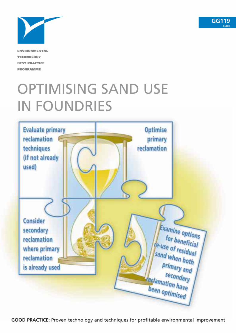
OPTIMISING SAND USEIN FOUNDRIES
GOOD PRACTICE: Proven technology and techniques for profitable environmental improvement
© Crown copyright. First printed March 1998.
This material may be freely reproduced except for sale or advertising purposes.
Printed on paper containing 75% post-consumer waste.
OPTIMISING SAND USE IN FOUNDRIES
This Good Practice Guide was produced by the
Environmental Technology Best Practice Programme
Prepared with assistance from:
The Castings Development Centre
With particular acknowledgement for contributions from:
Hepworth Minerals and Chemicals LtdRichards Engineering IncRugby CementThe University of Nottingham, Department of Civil Engineering

Until recently, UK foundries did not consider the disposal of waste sand to be a major problem.However, the increasing cost and scarcity of good quality virgin sand and escalating landfill costshave forced foundries to pay closer attention to sand management and reclamation.
This Good Practice Guide provides practical advice on the management and reclamation of:
■ chemically bonded sand based on the following binder systems:
- furan;
- alkaline phenolic;
- phenolic urethane;
- resin shell;
- sodium silicate;
■ greensand.
The factors affecting the choice of reclamation technique are discussed and the options available forthe reclamation of each type of sand system summarised in comparative tables.
The cost benefits of sand reclamation are emphasised and examples of the cost savings achievablewith primary and secondary reclamation are described. Action plans applicable to all foundriesseeking to reduce sand use and costs are given.
To remain competitive, foundries are urged to:
■ evaluate primary reclamation techniques (if not already adopted);
■ optimise primary reclamation;
■ consider secondary reclamation where primary reclamation is already used;
■ examine options for beneficial re-use of residual waste sand when both primary andsecondary reclamation have been optimised.
S U M M A R Y
Section Page
1 Why reclaim foundry sand? 11.1 Sand reclamation techniques 11.2 The sand balance diagram 3
2 Reducing operating costs by optimising sand use 62.1 Raw material purchase and disposal 62.2 Sand-to-metal ratios 62.3 Choice of binder systems 72.4 Metal yield 72.5 Cores 82.6 Factors affecting reclamation 82.7 Control tests for reclaimed sand 10
3 Choice of reclamation technique 113.1 Furan bonded sand 123.2 Alkaline phenolic bonded sand 133.3 Phenolic urethane bonded sand 143.4 Resin shell sand 153.5 Sodium silicate bonded sand 163.6 Greensand 17
4 The economic benefits of sand reclamation 194.1 How much could your foundry save with primary reclamation? 204.2 Evaluating the cost benefits of sand reclamation 204.3 Example cost savings 21
5 Action plans 245.1 Actions to reduce sand costs 245.2 Actions to reduce sand use 245.3 Actions to improve waste sand management 255.4 Practical steps for best practice in sand management 25
and reclamation5.5 Actions to improve sand storage 27
6 Beneficial re-use of waste sand 296.1 Possible applications for the re-use of waste sand 29
C O N T E N T S

In the foundry industry, sand is a valuable commodity. It can be reclaimed for return to the sandsystem, reducing the need to buy new sand and to pay ever-increasing waste disposal costs. Manyfoundries in the UK are reducing their operating costs by improved sand management and increaseduse of reclaimed sand.
To give some idea of the scale of the problem, the UK foundry industry currently spends nearly £35 million/year on purchasing over one million tonnes of new sand and disposing of a considerableproportion of this (as used sand) to landfill.
Foundry-quality sand will become more difficult to obtain and therefore more expensive to buy asUK stocks of sand diminish. The post-quarrying costs of improving the mineral to meet foundryacceptance criteria also increase the price of virgin sand. Other factors are also affecting rawmaterial costs. Because of the high capital cost of extraction, some quarries have closed prematurelywithout all the raw material being extracted. This has tended to increase delivery costs because thesand has to be transported further. Controls on sand excavation, eg post-closure landscapingrequirements, have also led to increased costs for quarry operators.
Until recently, the disposal of waste sand was not considered a major problem. However, there arenow fewer licensed landfill sites available for the disposal of controlled wastes. Waste sand thereforehas to be transported greater distances for disposal, resulting in increased haulage costs. Moreover,tighter legislative controls on wastes and waste disposal sites have led to a rapid escalation in disposalcosts. The landfill tax1 has also increased the cost of sending waste sand to landfill sites.
Paying more attention to sand management and increasing sand reclamation will enable foundriesto increase their profits and remain competitive. Table 1 summarises the advantages anddisadvantages of sand reclamation.
Advantages Disadvantages
Reduced purchases of new sand Some binder systems are not fully reclaimable
Lower waste disposal costs Capital outlay required
Decreased binder/catalyst costs More technical controls required
Improved casting quality Additional costs for pollution control, storage,
Foundries’ impact on the environment reduced distribution and blending
May require the use of more expensive binders
Table 1 Advantages and disadvantages of sand reclamation
This Guide describes practical measures to improve sand management and reclamation for foundriesusing chemically bonded sand (furan, alkaline phenolic, phenolic urethane, resin shell and sodiumsilicate) and greensand. Practical measures to improve the management of chemical binder systemsare described in Good Practice Guide (GG104) Cost-effective Management of Chemical Binders inFoundries, available free of charge through the Environmental Helpline on 0800 585794.
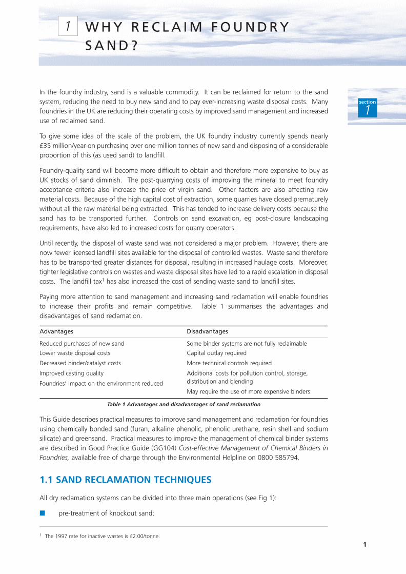
1.1 SAND RECLAMATION TECHNIQUES
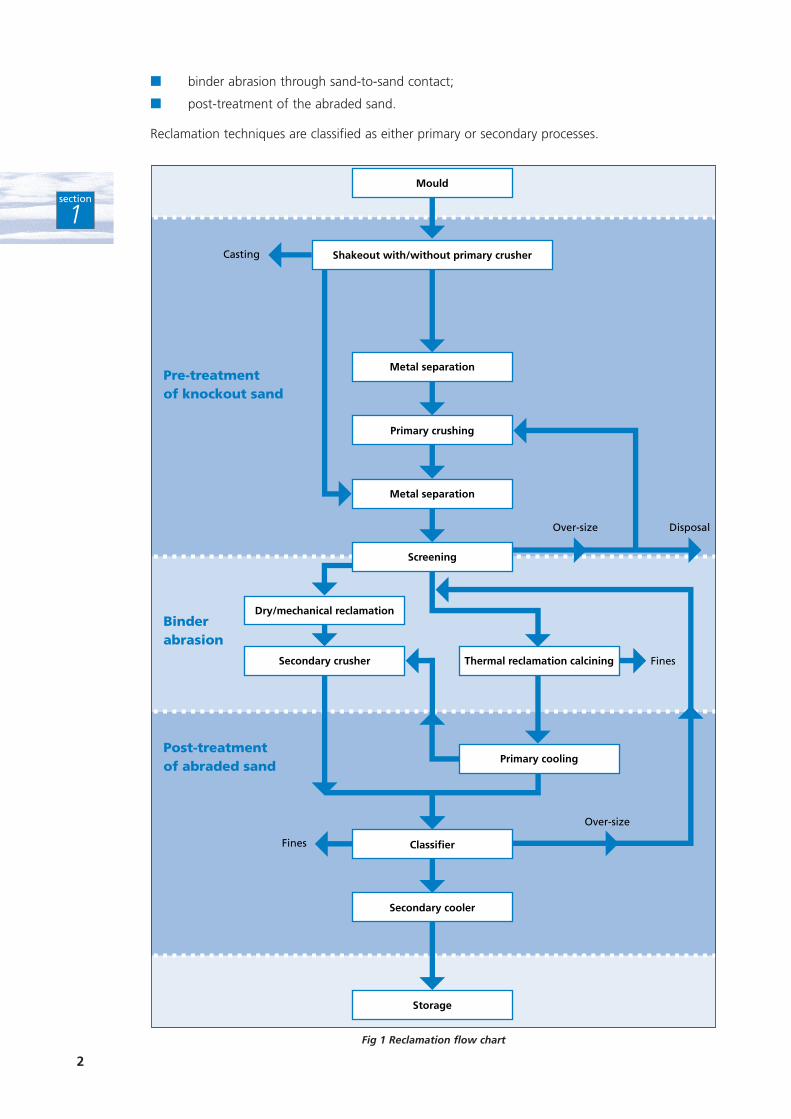
All dry reclamation systems can be divided into three main operations (see Fig 1):
■ pre-treatment of knockout sand;
1
W H Y R E C L A I M F O U N D R YS A N D ?
1
section
1
1 The 1997 rate for inactive wastes is £2.00/tonne.
2
section
1
■ binder abrasion through sand-to-sand contact;
■ post-treatment of the abraded sand.
Reclamation techniques are classified as either primary or secondary processes.
Fig 1 Reclamation flow chart
Mould
Metal separation
Primary crushing
Metal separation
Dry/mechanical reclamation
Secondary crusher Thermal reclamation calcining
Primary cooling
Secondary cooler
Storage
Screening
Shakeout with/without primary crusher
Over-size
Over-size
Fines
Fines
Casting
Disposal
Classifier
Pre-treatmentof knockout sand
Post-treatmentof abraded sand
Binderabrasion
3
section
1
1.1.1 Primary reclamation
Primary reclamation, also known as attrition or particulation, involves breaking down the sand frommoulds or cores to its original grain size. This includes screening the sand, removing tramp metal,and separating and removing fines and over-sized agglomerates. The sand is then cooled beforebeing sent for storage, returned to the sand system or blended with new sand.
At this stage, the sand grains are likely to retain a partial coating of spent binder. This affects theamount of reclaimed sand that can be used to make moulds and, more particularly, cores. New sandtherefore has to be added to ensure that the sand mix produces adequate mould and core strengthand subsequent casting quality. Primary reclaimed sand is not generally of sufficient quality to beused for coremaking without further processing to remove residual binder materials and is thereforeused principally for moulds.
The main primary reclamation techniques are:
■ shot blast;
■ rotating drum;
■ vibration.
1.1.2 Secondary reclamation
Secondary reclamation involves further processing of the previously particulated sand to removeresidual binder. The sand is returned to a quality similar to, or better than, that of new sand.Foundries using secondary reclamation have, in some cases, virtually eliminated the need for newsand.
To remove residual binder, more aggressive techniques are required than for primary reclamation.The main secondary reclamation techniques are:
■ high energy attrition, either:
- pneumatic;
- mechanical;
- centrifugal;
■ wet scrubbing;
■ thermal treatment, usually in a fluidised bed.
Further details of the different reclamation techniques are given in Environmental PerformanceGuide (EG4) Chemically Bonded Sand: Use and Reclamation, available free of charge through theEnvironmental Helpline on 0800 585794. Equipment manufacturers will also be able to provideinformation.
Section 3 indicates the reclamation techniques suitable for use with the six main sand systems.
1.2 THE SAND BALANCE DIAGRAM
There is a considerable difference between the use of 100% reclaimed sand to produce moulds andcores and the achievement of 100% sand reclamation. For a number of reasons, eg sand losses dueto inefficiencies in the sand system, burn-on and the need to remove dust and fines, 100% sandreclamation cannot be achieved. Even with thermal reclamation, dust losses of 5 - 8% can beexpected.
Preparation of a sand balance diagram helps to determine a foundry’s true reclamation rate andpotential for cost savings.
4
section
1
1.2.1 Mechanical reclamation only
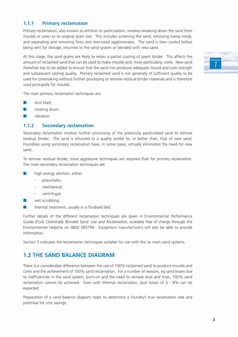
Fig 2 is an example of a sand balance diagram for a foundry using a blend of 70% mechanicallyreclaimed sand and 30% new sand for moulding. The system contains 100 tonnes of sand.
To obtain the necessary core properties, core production requires 10 tonnes of new sand. This leavesa requirement for 90 tonnes of blended sand for moulding purposes.
Fig 2 shows that to achieve a balance, the blended sand for moulding will comprise 63 tonnes ofreclaimed sand and 27 tonnes of new sand. Although mould production uses 70% reclaimed sand,the true reclamation rate is only 63%.
1.2.2 The effect of using new sand for coremaking
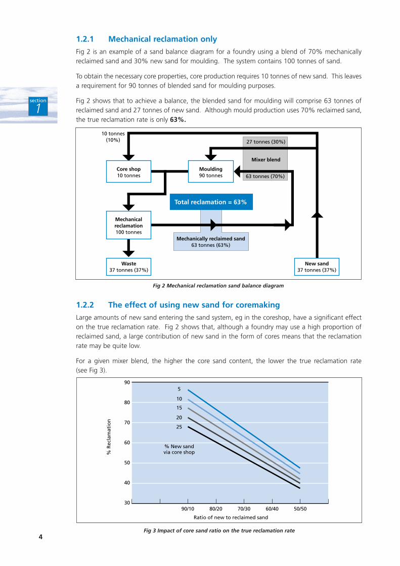
Large amounts of new sand entering the sand system, eg in the coreshop, have a significant effecton the true reclamation rate. Fig 2 shows that, although a foundry may use a high proportion ofreclaimed sand, a large contribution of new sand in the form of cores means that the reclamationrate may be quite low.
For a given mixer blend, the higher the core sand content, the lower the true reclamation rate (see Fig 3).
Fig 2 Mechanical reclamation sand balance diagram
Mechanicalreclamation100 tonnes
Core shop10 tonnes
Moulding90 tonnes
10 tonnes(10%) 27 tonnes (30%)
63 tonnes (70%)
Mechanically reclaimed sand63 tonnes (63%)
Waste37 tonnes (37%)
New sand37 tonnes (37%)
Total reclamation = 63%
Mixer blend
Fig 3 Impact of core sand ratio on the true reclamation rate
90
80
70
60
50
40
3090/10 80/20 70/30
Ratio of new to reclaimed sand
% R
ecla
mat
ion
60/40 50/50
% New sandvia core shop
5
10
15
20
25
5
1.2.3 Thermal/mechanical reclamation
The open loop shown in Fig 2 can be closed by introducing a secondary reclamation process toreclaim the proportion of sand that is currently thrown away. However, to close the loop fully, thissecondary process must meet the following criteria:
■ no degradation of the sand grain size;
■ contamination stabilised to a level at which casting quality will not be adversely affected.
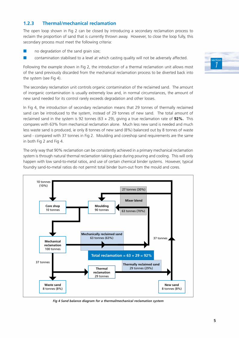
Following the example shown in Fig 2, the introduction of a thermal reclamation unit allows mostof the sand previously discarded from the mechanical reclamation process to be diverted back intothe system (see Fig 4).
The secondary reclamation unit controls organic contamination of the reclaimed sand. The amountof inorganic contamination is usually extremely low and, in normal circumstances, the amount ofnew sand needed for its control rarely exceeds degradation and other losses.
In Fig 4, the introduction of secondary reclamation means that 29 tonnes of thermally reclaimedsand can be introduced to the system, instead of 29 tonnes of new sand. The total amount ofreclaimed sand in the system is 92 tonnes (63 + 29), giving a true reclamation rate of 92%. Thiscompares with 63% from mechanical reclamation alone. Much less new sand is needed and muchless waste sand is produced, ie only 8 tonnes of new sand (8%) balanced out by 8 tonnes of wastesand - compared with 37 tonnes in Fig 2. Moulding and coreshop sand requirements are the samein both Fig 2 and Fig 4.
The only way that 90% reclamation can be consistently achieved in a primary mechanical reclamationsystem is through natural thermal reclamation taking place during pouring and cooling. This will onlyhappen with low sand-to-metal ratios, and use of certain chemical binder systems. However, typicalfoundry sand-to-metal ratios do not permit total binder burn-out from the mould and cores.
section
1
Fig 4 Sand balance diagram for a thermal/mechanical reclamation system
Mechanicalreclamation100 tonnes
Core shop10 tonnes
Moulding90 tonnes
10 tonnes(10%)
Mechanically reclaimed sand63 tonnes (63%)
37 tonnes
37 tonnes
Thermally reclaimed sand29 tonnes (29%)
Total reclamation = 63 + 29 = 92%
Waste sand8 tonnes (8%)
New sand8 tonnes (8%)
Thermalreclamation29 tonnes
27 tonnes (30%)
63 tonnes (70%)
Mixer blend
6
section
2
2.1 RAW MATERIAL PURCHASE AND DISPOSAL
A foundry’s annual consumption of sand and binders can be calculated from its suppliers’ invoices.The amount of waste sand may be more difficult to determine as many foundries handle all wastesin the same way. Segregating waste streams and avoiding the contamination of inactive wastes bygeneral refuse (charged at the higher rate of landfill tax) or hazardous materials classified as specialwaste, will facilitate reclamation and reduce landfill costs.
Sand is generally purchased to replace a similar quantity of sand disposed of as waste. However, thewaste sand also has a potential for reclamation.
It is essential to examine when and how waste sand is generated. Not only will this help you toidentify opportunities to minimise waste, but will also allow you to manage the waste sand properly.In the ideal case, the foundry produces moulds continuously and at the same rate as they are beingknocked out. The system is therefore in equilibrium. In the worst case, eg where large castings areproduced, it can take several days to assemble and cast the mould. At knockout, a surge of sand isproduced which requires storage.
Arrangements should also be made to allow the new sand needed to make up losses to enter thecycle without affecting the reclamation system and potentially displacing sand to waste.
2.2 SAND-TO-METAL RATIOS
Sand-to-liquid metal ratios are a further parameter that can be controlled to optimise sand use andreduce operating costs.
The amount of sand mixed per tonne of metal poured varies for different types of metal anddifferent sizes and shapes of castings. In each case, the amount of sand must be sufficient to ensureadequate mould strength. Once an adequate mould strength has been achieved, there is noadditional benefit in using more sand to create a larger mould.
Although foundries may feel more confident with over-sized moulds, using more sand than isnecessary only increases production costs. Optimising mixed sand (ie sand and binder) consumptionhas many advantages:
■ increased productivity;
■ less sand is required, leading to reduced sand costs;
■ binder costs are reduced because less binder-coated sand is used per casting;
■ emissions to atmosphere from mixing and casting operations are reduced because less sandis mixed for each casting;
■ natural reclamation is higher in thermally-degradable binder systems because the proportionof burnt out sand is greater (see Section 2.6);
■ burn-out makes particulation easier;
■ burn-out results in lower residual binder levels in the reclaimed sand, which allows greateramounts of sand to be re-used.
Any foundry operating with a sand-to-liquid metal ratio in excess of those listed in Table 2 shouldreview its production methods, as there may be scope to reduce sand consumption.
R E D U C I N G O P E R AT I N G C O S T S B YO P T I M I S I N G S A N D U S E
2
Alloy sector Sand-to-liquid metal ratio
Iron up to 4:1
Steel up to 5:1
Copper up to 4:1
Aluminium up to 12:1
Table 2 Typical sand-to-liquid metal ratios in UK foundries
Further details about sand-to-metal ratios are given in Environmental Performance Guide (EG4) Chemically Bonded Sand: Use and Reclamation and Environmental Performance Guide (EG5)Foundry Greensand: Use and Reclamation. Both Guides are available free of charge through theEnvironmental Helpline on 0800 585794.
2.3 CHOICE OF BINDER SYSTEMS
Many foundries use more than one type of binder. Undertaking a review can lead to the use offewer binder systems. This could increase the potential for reclamation, and reduce:
■ the capital tied up in stock;
■ the need for different handling requirements;
■ the need for training in the use of multiple binder systems;
■ labour costs;
■ administrative effort.
The following factors should also be considered:
■ the choice of binder system affects the amount of sand that can be reclaimed;
■ some binder systems are incompatible with others;
■ the base sand used for different binder systems may be of different sieve gradings;
■ the presence of heavy sands, eg chromite tends to segregate in fluidised beds and hoppers.
Good Practice Guide (GG104) Cost-effective Management of Chemical Binders in Foundriesdescribes how foundries can achieve significant cost and other benefits by improving themanagement of their chemical binder systems.
2.4 METAL YIELD
Metal yield - the ratio of the amount of metal melted to the weight of the finished castings - doesnot have a direct effect on sand use. However, an increase in yield may result in fewer moulds beingproduced, which means that less sand is used. Five main factors affect metal yield:
■ quality requirements;
■ choice of mould-box size;
■ the extent of runner and feeder systems;
■ metal shrinkage;
■ scrap casting rate.
Lower metal yields are generally associated with higher integrity products where superior qualitystandards may be required, necessitating a more extensive feeding system. Lower yields, however,may also be indicative of higher scrap rates and excessive feeding systems. In these circumstances,foundries should review process control and mould production methods.
7
section
2
8
section
2
The average metal yields for the main alloy sectors are given in Table 3 which shows that all foundriescould benefit from considering metal yield if this leads to the production of fewer moulds. Binderand new sand purchases - together with the amount of sand processed - provide a check on actualbinder addition levels (as distinct from nominal addition levels). Given the high cost of binders, thiscan result in significant savings.
Sector Average metal yieldChemically bonded sand Greensand
Iron:
grey 69% 68%
spheroidal graphite (SG) 64% 63%
Steel 51% Not applicable
Aluminium 71% 57%
Copper 63% 58%
Table 3 Average metal yields in the main alloy sectors
The range of yields in different foundry sectors are considered in Environmental Performance Guide(EG4) Chemically Bonded Sand: Use and Reclamation and Environmental Performance Guide (EG5)Foundry Greensand: Use and Reclamation.
2.5 CORES
Cores are a critical part of a mould since they become virtually surrounded by liquid metal. As such,they require high-quality materials. Most foundries therefore use new sand for coremaking.
If a foundry produces only a small quantity of cores, this may provide a cost-effective entry point forthe new sand needed to keep the sand system full.
If a foundry uses large quantities of cores or it operates a facing sand practice, primary reclamationalone may lead to a build-up of reclaimed sand that cannot be used. It may therefore beadvantageous to install a secondary reclamation unit to return the waste sand to a quality suitablefor coremaking.
2.6 FACTORS AFFECTING RECLAMATION
A number of factors affect sand reclamation and thus influence the quality of the castings producedwith reclaimed sand. These factors are described below in no particular order of priority.
2.6.1 Type of binder and catalyst
Organic materials are volatilised by the heat generated during casting. For primary reclamation, ameasure of the amount of organic binder remaining in the sand can be obtained by determining theamount of combustible material present. This is obtained in the form of the loss on ignition (LOI)value for the sand. A high LOI indicates a high residual level of binder which, in turn, suggests alow level of binder degradation on casting. The LOI value is controlled by using less binder anddiluting the reclaimed sand with new sand. Although effective, dilution uses increasingly expensiveraw materials.
The chemical composition of the binder system is also important because it may contain elementsassociated with casting defects. Accumulation of elements such as nitrogen, phosphorus, sodiumand sulphur in a reclaimed sand - over a number of cycles - may ultimately exceed acceptable levelsand lead to a fall in compression strength.
9
section
2
2.6.2 Sand grain shape and sieve grading
The more angular the sand grain, the greater the surface area and hence the greater the quantityof residual binder that will adhere to it. Attrition can reduce the overall surface area of the sandgrains, as the abrasion between individual sand grains makes them more rounded.
Most reclamation units incorporate an attrition stage to break down any sand lumps. Grain shapeis thus progressively changed over a number of reclamation cycles. The production of morespherical grains reduces the amount of residual binder in the sand, which lowers the amount ofcombustible material in the sand, and reduces the level of fresh binder required which reducesoperating costs.
Sieve grading indicates the distribution of grain sizes. To avoid the casting problems associated withlarge lumps of sand and fine sand grains (ie less than 70 µm), reclamation plants contain crushing,sieving and classifying units to produce a sand with the required screen distribution. Reclamationthus removes tramp metal, dust and most of the residual binder, and restores the sand to its originalgrain size.
2.6.3 Type of metal poured
The pouring temperature affects the quantity of heat transferred to the sand and thus the amountof binder burnt away. There is less self-reclamation with lower melting point metals such asaluminium, than with iron or steel.
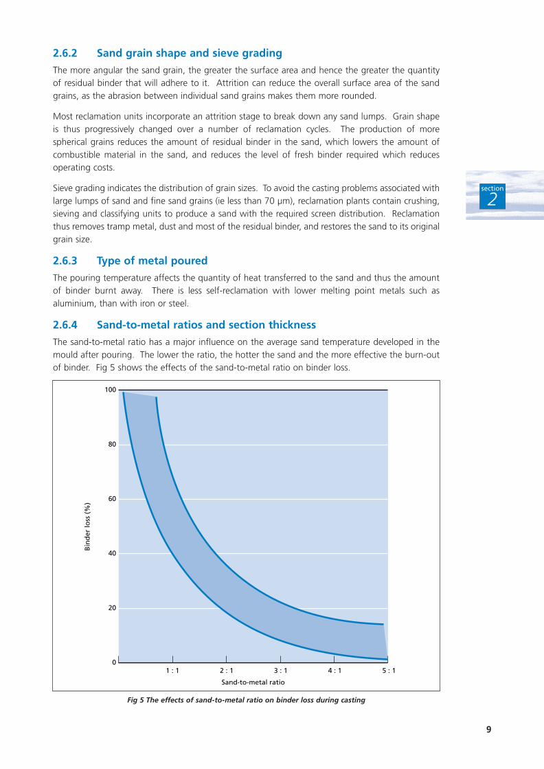
2.6.4 Sand-to-metal ratios and section thickness
The sand-to-metal ratio has a major influence on the average sand temperature developed in themould after pouring. The lower the ratio, the hotter the sand and the more effective the burn-outof binder. Fig 5 shows the effects of the sand-to-metal ratio on binder loss.
Fig 5 The effects of sand-to-metal ratio on binder loss during casting
0
20
40
60
80
100
1 : 1 2 : 1 3 : 1
Sand-to-metal ratio
Bin
der
loss
(%
)
4 : 1 5 : 1
The surface area of the casting and its section thickness also influences the extent of binder removal.The larger the surface area of the casting, the more sand will be brought into contact with hotmetal, and the greater the amount of burn-out of the binder.
2.6.5 Time between metal pouring and shakeout
The longer the delay between pouring and shakeout, the further the heat from the metal canpenetrate into the sand mass. This destroys more of the binder and thus helps to reduce the levelof residual binder to be removed by reclamation.
2.6.6 Sand temperature
Good control of sand temperature is essential for optimum results and consistent performance.Where sand is reclaimed, a cooler classifier should be used to ensure that the temperature of thereturn sand is acceptable. Good Practice Guide (GG104) Cost-effective Management of ChemicalBinders in Foundries explains the benefits of controlling sand temperature.
2.7 CONTROL TESTS FOR RECLAIMED SAND
The properties of the reclaimed sand have a significant influence on the resulting moulds and cores.Regular control testing of the reclaimed sand and/or reclaimed/new sand mix is therefore essential.There are six main control tests for reclaimed sand:
■ mechanical analysis or sieve grading of the reclaimed sand;
■ moisture content of the new sand;
■ loss on ignition (LOI);
■ sand temperature and foundry humidity levels;
■ acidity/alkalinity of the reclaimed sand;
■ specific chemical analysis.
10
section
2
11
section
3
There are a number of options available for reclaiming greensand and the different types ofchemically bonded sand. These choices - together with their advantages and disadvantages - aredescribed in this Section.
The price of reclamation equipment depends on the throughput and complexity of the system. Eachtype of equipment is available in a range of prices starting from £21 000 for a 1 tonne/hour vibrationsystem (1997 prices). Section 4 explains how to evaluate the cost benefits of reclamation and givesexample cost savings.
The Environmental Helpline on 0800 585794 can provide contact details for suppliers of differenttypes of reclamation equipment, from whom detailed information on capital and operating costscan be obtained.
When selecting reclamation equipment, remember to confirm with the manufacturer that you willcontinue to achieve the emission limits specified in your process authorisation.
C H O I C E O F R E C L A M AT I O NT E C H N I Q U E
3
12
section
3
3.1 FURAN BONDED SAND
3.1.1 Primary reclamation
This binder system is almost totally organic and thus destroyed by heat. Many foundries reclaimfuran bonded sand using a simple, low-energy attrition or particulation process, while also takingadvantage of the thermal reclamation that occurs during casting. This mechanical process typicallyachieves 60 - 90% reclamation (average 80%).
Primary reclamation is limited by the build-up of residual resin and catalyst on the sand grains. Thiscauses variations in the loss on ignition (LOI) value, acid demand value, and residual levels of sulphur,nitrogen and dust. In turn, these can lead to casting defects and/or excessive fumes during pouring.
As total binder removal is not achieved, binder addition levels can be reduced by typically 0.15 - 0.20% on rebonding. There is also a proportionate reduction in the amount of catalystneeded. This benefit is also partly due to the general improvement in grain shape, caused by arounding of the sand grains.
3.1.2 Secondary reclamation
There is still considerable potential in the UK foundry industry for the use of secondary reclamationto return the sand to its original state.
Thermal reclamation is the preferred option, unless the binder has been catalysed by phosphoricacid, which cannot be removed by thermal processing. At the optimum operating temperature ofapproximately 800°C, the sand becomes ‘as new’. Exhaust emissions are within the limits specifiedin the relevant Secretary of State’s Process Guidance Notes. The only solid waste is a small amountof inert silica dust.
Wet reclamation is not generally feasible as the furan binder contains only a small amount of water-soluble catalyst.
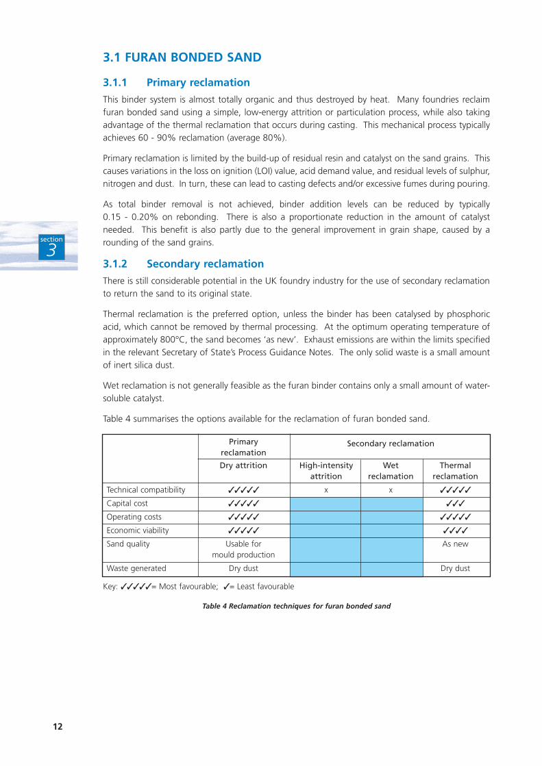
Table 4 summarises the options available for the reclamation of furan bonded sand.
Primary Secondary reclamationreclamation
Dry attrition High-intensity Wet Thermal attrition reclamation reclamation
Technical compatibility ✓✓✓✓✓ x x ✓✓✓✓✓
Capital cost ✓✓✓✓✓ ✓✓✓
Operating costs ✓✓✓✓✓ ✓✓✓✓✓
Economic viability ✓✓✓✓✓ ✓✓✓✓
Sand quality Usable for As newmould production
Waste generated Dry dust Dry dust
Key: ✓✓✓✓✓= Most favourable; ✓= Least favourable
Table 4 Reclamation techniques for furan bonded sand
13
section
3
3.2 ALKALINE PHENOLIC BONDED SAND
The controlling factor in the reclamation of this type of chemically bonded sand is the residualpotassium content in the reclaimed sand. The reduction in strength of the rebonded sand is minimalup to 0.15% residual potassium, but falls rapidly above this level. New sand additions are essentialto ensure acceptable levels of potassium.
In terms of primary reclamation, simple vibratory attrition is now capable of achieving 80 - 85%reclamation.
Secondary reclamation using attrition or dry scrubbing does not offer any additional benefits to thefoundry; more heat and dust are generated and the reduction in residual binder levels is notsignificant.
Until recently, thermal reclamation was problematic as potassium salt residues tended to melt andfrit in the fluidised bed, producing an agglomerated mass. However, use of a proprietary additive -based on china clay or a sugar derivative - with previously attrited sand has overcome this problem.The additive converts potassium salts to a thermally stable form and reduces the level of residualpotassium to an amount that does not affect the bond strength. A further benefit is that thereclaimed sand is suitable for use with other binder systems, eg phenolic urethane.
Although use of an additive has cost implications, these are not significant. Thermal reclamation ofalkaline phenolic bonded sand now offers a technically and economically feasible route to increasingthe use of reclaimed sand.
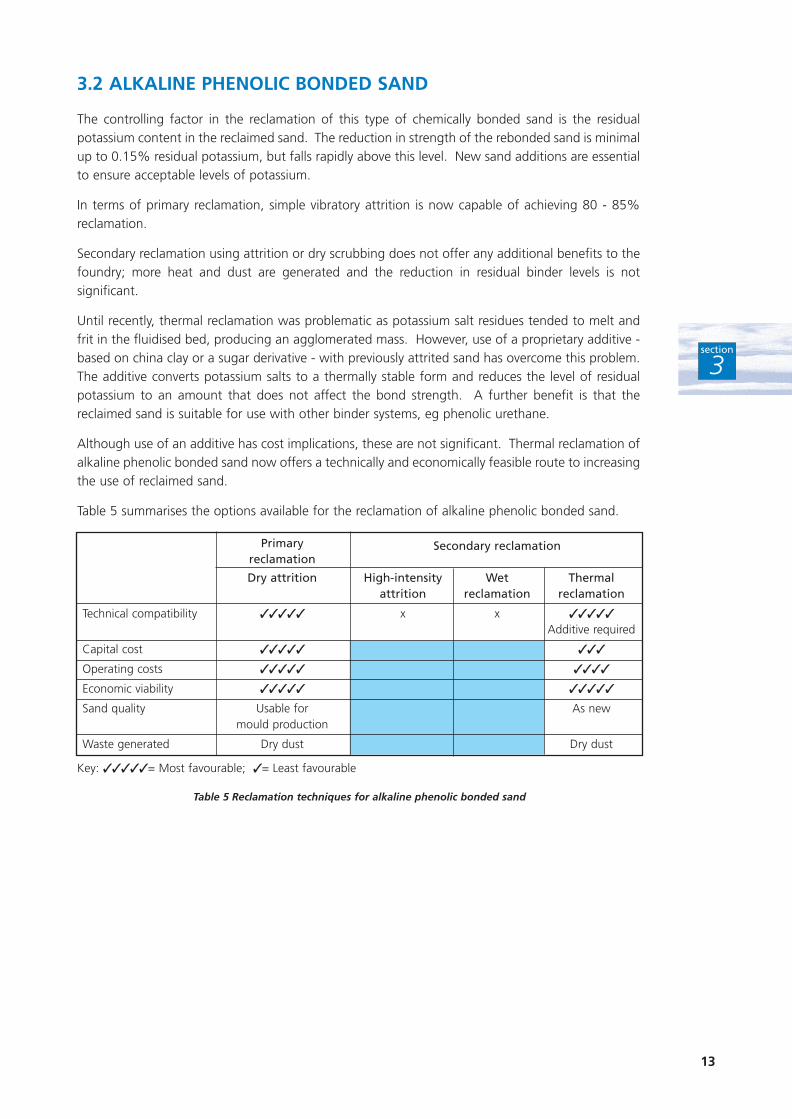
Table 5 summarises the options available for the reclamation of alkaline phenolic bonded sand.
Primary Secondary reclamationreclamation
Dry attrition High-intensity Wet Thermal attrition reclamation reclamation
Technical compatibility ✓✓✓✓✓ x x ✓✓✓✓✓
Additive required
Capital cost ✓✓✓✓✓ ✓✓✓
Operating costs ✓✓✓✓✓ ✓✓✓✓
Economic viability ✓✓✓✓✓ ✓✓✓✓✓
Sand quality Usable for As newmould production
Waste generated Dry dust Dry dust
Key: ✓✓✓✓✓= Most favourable; ✓= Least favourable
Table 5 Reclamation techniques for alkaline phenolic bonded sand

14
section
3
3.3 PHENOLIC URETHANE BONDED SAND
This totally organic binder system poses no major problems for reclamation. The binder decomposeson exposure to heat, so a certain amount of thermal reclamation occurs during casting. Low-energyattrition or particulation is capable of achieving approximately 80% reclamation. This upper limit isdue to the build-up of volatiles in the sand, which requires dilution with new sand.
Wet attrition is not feasible because the binder is insoluble.
Thermal reclamation is viable, provided that any iron oxide present is first removed by magneticseparation. Iron oxide is sometimes added to this binder system to reduce casting defects. Failureto remove iron oxide can result in the production of large quantities of low-melting point materialsduring reclamation. This leads to a loss of refractoriness in the reclaimed sand, causing poor mouldquality.
New sand additions can generally be limited to approximately 8%.
Table 6 summarises the options available for the reclamation of phenolic urethane bonded sand.
Primary Secondary reclamationreclamation
Dry attrition High-intensity Wet Thermal attrition reclamation reclamation
Technical compatibility ✓✓✓✓✓ x x ✓✓✓✓✓
Iron oxide additions mustbe removed
Capital cost ✓✓✓✓✓ ✓✓✓
Operating costs ✓✓✓✓✓ ✓✓✓✓✓
Economic viability ✓✓✓✓✓ ✓✓✓✓✓
Sand quality Usable for As newmould production
Waste generated Dry dust Dry dust
Key: ✓✓✓✓✓= Most favourable; ✓= Least favourable
Table 6 Reclamation techniques for phenolic urethane bonded sand
15
3.4 RESIN SHELL SAND
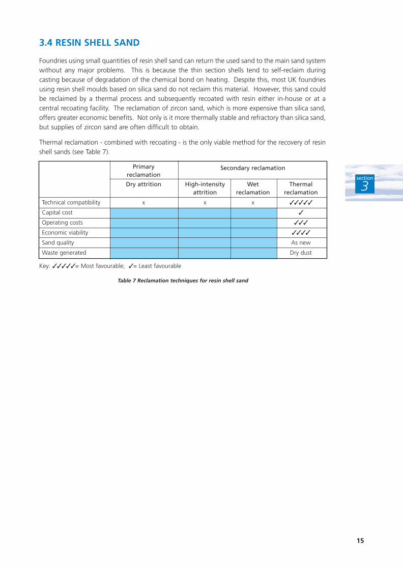
Foundries using small quantities of resin shell sand can return the used sand to the main sand systemwithout any major problems. This is because the thin section shells tend to self-reclaim duringcasting because of degradation of the chemical bond on heating. Despite this, most UK foundriesusing resin shell moulds based on silica sand do not reclaim this material. However, this sand couldbe reclaimed by a thermal process and subsequently recoated with resin either in-house or at acentral recoating facility. The reclamation of zircon sand, which is more expensive than silica sand,offers greater economic benefits. Not only is it more thermally stable and refractory than silica sand,but supplies of zircon sand are often difficult to obtain.
Thermal reclamation - combined with recoating - is the only viable method for the recovery of resinshell sands (see Table 7).
section
3
Primary Secondary reclamationreclamation
Dry attrition High-intensity Wet Thermal attrition reclamation reclamation
Technical compatibility x x x ✓✓✓✓✓
Capital cost ✓
Operating costs ✓✓✓
Economic viability ✓✓✓✓
Sand quality As new
Waste generated Dry dust
Key: ✓✓✓✓✓= Most favourable; ✓= Least favourable
Table 7 Reclamation techniques for resin shell sand
16
section
3
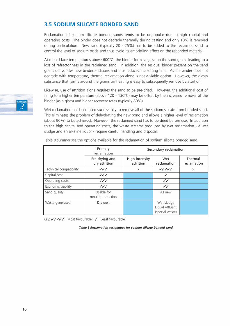
3.5 SODIUM SILICATE BONDED SAND
Reclamation of sodium silicate bonded sands tends to be unpopular due to high capital andoperating costs. The binder does not degrade thermally during casting and only 10% is removedduring particulation. New sand (typically 20 - 25%) has to be added to the reclaimed sand tocontrol the level of sodium oxide and thus avoid its embrittling effect on the rebonded material.
At mould face temperatures above 600°C, the binder forms a glass on the sand grains leading to aloss of refractoriness in the reclaimed sand. In addition, the residual binder present on the sandgrains dehydrates new binder additions and thus reduces the setting time. As the binder does notdegrade with temperature, thermal reclamation alone is not a viable option. However, the glassysubstance that forms around the grains on heating is easy to subsequently remove by attrition.
Likewise, use of attrition alone requires the sand to be pre-dried. However, the additional cost offiring to a higher temperature (above 120 - 130°C) may be offset by the increased removal of thebinder (as a glass) and higher recovery rates (typically 80%).
Wet reclamation has been used successfully to remove all of the sodium silicate from bonded sand.This eliminates the problem of dehydrating the new bond and allows a higher level of reclamation(about 90%) to be achieved. However, the reclaimed sand has to be dried before use. In additionto the high capital and operating costs, the waste streams produced by wet reclamation - a wetsludge and an alkaline liquor - require careful handling and disposal.
Table 8 summarises the options available for the reclamation of sodium silicate bonded sand.
Primary Secondary reclamationreclamation
Pre-drying and High-intensity Wet Thermal dry attrition attrition reclamation reclamation
Technical compatibility ✓✓✓ x ✓✓✓✓✓ x
Capital cost ✓✓✓ ✓
Operating costs ✓✓✓ ✓✓
Economic viability ✓✓✓ ✓✓
Sand quality Usable for As newmould production
Waste generated Dry dust Wet sludgeLiquid effluent(special waste)
Key: ✓✓✓✓✓= Most favourable; ✓= Least favourable
Table 8 Reclamation techniques for sodium silicate bonded sand
17
3.6 GREENSAND
3.6.1 Primary reclamation
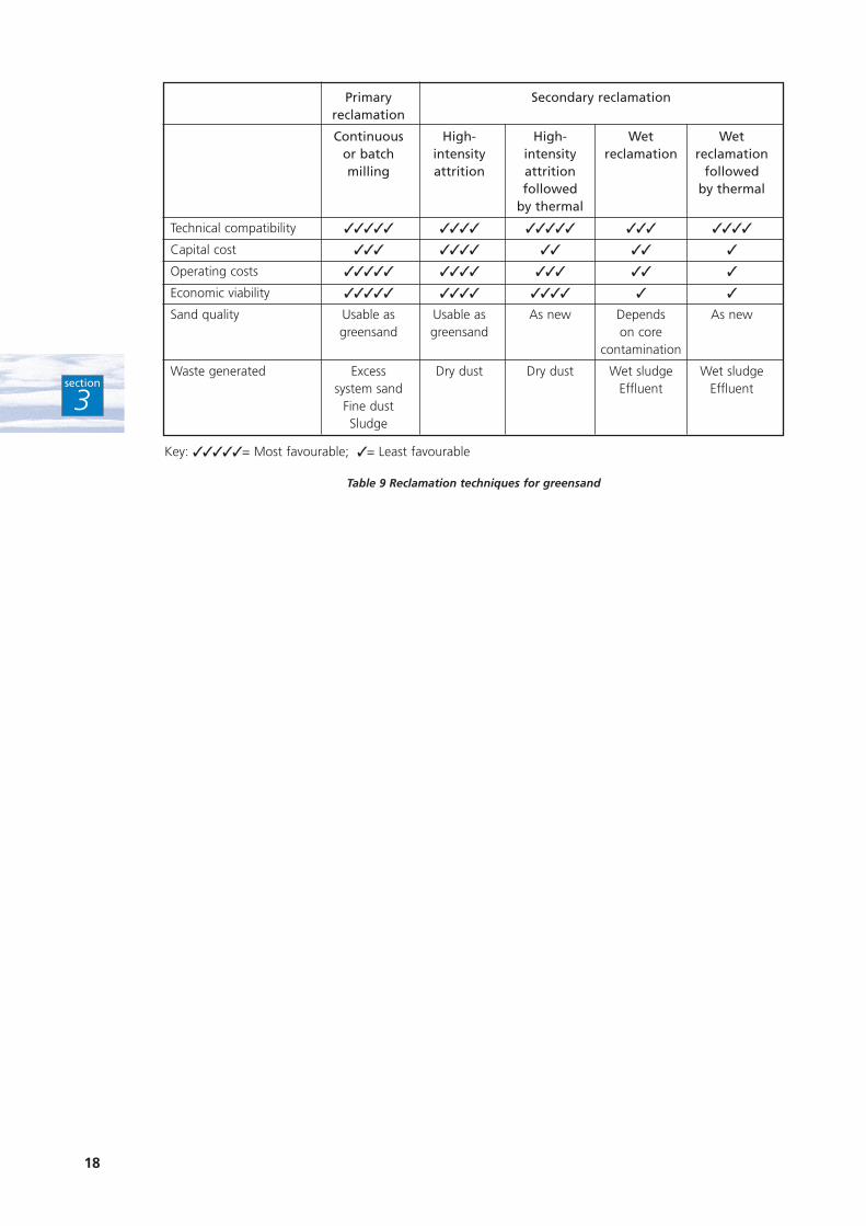
Most greensand foundries have traditionally carried out primary reclamation using batch orcontinuous mills, magnetic separators, rotary screens, etc. However, new sand must be added tothe reclaimed sand to counteract the build-up of ‘dead’ materials (clay and spent carbonaceousmaterials), contaminants and fines in the system. Furthermore, the addition of spent sand fromcores results in an excess of primary reclaimed sand requiring storage.
To increase the use of reclaimed sand and minimise the purchase of new sand, it is possible to usesecondary reclamation to return the sand to a quality as good as, or better than, new sand. Thereclaimed sand can then be used for coremaking. The reclamation process must also be able to dealwith residual chemical binders from the cores (frequently a considerable percentage of the totalspent sand).
3.6.2 Secondary reclamation
The main options available for the secondary reclamation of greensand are high-intensity dryattrition (often combined with fluidised bed calciners) or wet reclamation techniques.
Simple dry attrition is not a suitable method of secondary reclamation for greensand as it is notsufficiently intensive to remove the ‘dead’ clay and coal-dust present in the spent sand.
Wet reclamation is an efficient method of removing ‘live’ clay, coal-dust, coal-dust substitutes andalkaline materials, eg those left over from alkaline phenolic cores. Combining wet reclamation witha calcining treatment at 775°C improves efficiency, but additives are sometimes necessary todeactivate any residual ‘live’ clay and make it easier to remove. In addition to the process’s highcapital and operating costs, the effluent and clay/coal-dust sludge generated have to be monitoredand controlled.
More aggressive attrition processes, eg high-intensity or rotary mechanical scrubbers, are nowavailable. High-intensity attrition tends to leave a residue of clay (up to 0.7%) on the sand grains,thus making them unsuitable for coremaking. However, ways of improving clay removal are beingdeveloped. Rotary mechanical processes and pneumatic attrition are successful in mechanicallystripping the coal-dust, clay and chemical binders from the sand grains. Such reclaimers are oftenpreceded by a fluidised bed calciner operating at 750 - 800°C; this has the advantage of renderingthe clay inactive and removing any residual organic binders from entrained core materials.Subsequent mechanical scrubbing requires less energy and is more efficient. This mechanicalcleaning can be carried out in fluidised beds that also operate as sand coolers.
When the spent sand contains alkaline phenolic core materials, it may be necessary to use additivesin the fluidised bed to prevent fritting of the sand grains. Unless the quantity of fritted particles islarge, this is not a major problem as the particles should be removed in the classification process.However, fritting increases the pH of the sand, which can affect the subsequent bond strength andbench life of the rebonded core sand.
Any thermal reclamation process must be able to take into account variations in the LOI value of thesand mix.
Table 9 summarises available techniques for greensand reclamation.
section
3
18
section
3
Primary Secondary reclamationreclamation
Continuous High- High- Wet Wet or batch intensity intensity reclamation reclamationmilling attrition attrition followed
followed by thermalby thermal
Technical compatibility ✓✓✓✓✓ ✓✓✓✓ ✓✓✓✓✓ ✓✓✓ ✓✓✓✓
Capital cost ✓✓✓ ✓✓✓✓ ✓✓ ✓✓ ✓
Operating costs ✓✓✓✓✓ ✓✓✓✓ ✓✓✓ ✓✓ ✓
Economic viability ✓✓✓✓✓ ✓✓✓✓ ✓✓✓✓ ✓ ✓
Sand quality Usable as Usable as As new Depends As newgreensand greensand on core
contamination
Waste generated Excess Dry dust Dry dust Wet sludge Wet sludge system sand Effluent Effluent
Fine dust Sludge
Key: ✓✓✓✓✓= Most favourable; ✓= Least favourable
Table 9 Reclamation techniques for greensand
19
The primary objective of every foundry is to produce consistently good-quality castings for least cost.The main reason for optimising sand management and installing reclamation equipment is usuallyto reduce operating costs. If the cost benefits of reclamation are significant, any minor technicalcomplications associated with controlling and using the reclaimed sand are generally acceptable.
Sand reclamation produces cost savings for foundries through:
■ reduced purchases of new sand;
■ reduced disposal of spent sand.
These savings have to be offset by the costs of:
■ providing the necessary capital investment;
■ operating the reclamation plant;
■ plant maintenance and repair;
■ any process modifications, eg sand quality, grain size or changing to a different binder systemwith a greater potential for reclamation - these costs are generally low.
To be economically viable, the reclamation process must produce significant savings in annualoperating costs and an acceptable payback on capital investment. For most foundries, the savingson new sand purchase and waste disposal are so large as to outweigh other considerations.
section
4
T H E E C O N O M I C B E N E F I T S O FS A N D R E C L A M AT I O N
4
Upgraded binder system produces extra savings
Having installed a mechanical reclamation plant, J Youle & Co Ltd worked in partnership withits binder supplier to gradually increase the level of sand reclamation. A detailed analysis ofthe sand quality was carried out and resin/hardener rates adjusted to produce optimumperformance. A 70% reclamation level was successfully achieved while reducing resin additionrates from 1.65% to 1.5%. Towards the end of the planned programme, the Companyupgraded its alkaline phenolic binder system to one specifically designed for high reclamationlevels. The type of virgin silica sand was also changed to maintain sand strength. Thesechanges enabled the foundry to increase its reclamation level to 80% while maintaining mouldquality.
The additional costs (new binder system, equipment operation and finance costs) of over£3 500/year were more than offset by cost savings of nearly £25 000/year from a reduced needfor virgin sand and lower disposal costs. The net annual cost savings gave a payback on theCompany’s investment of around 18 months.
For more details, see Good Practice Case Study (GC99) Small Foundry Benefits from Investment in Sand Reclamation, available free of charge through the Environmental Helplineon 0800 585794.
20
section
4
4.1 HOW MUCH COULD YOUR FOUNDRY SAVE WITH PRIMARYRECLAMATION?
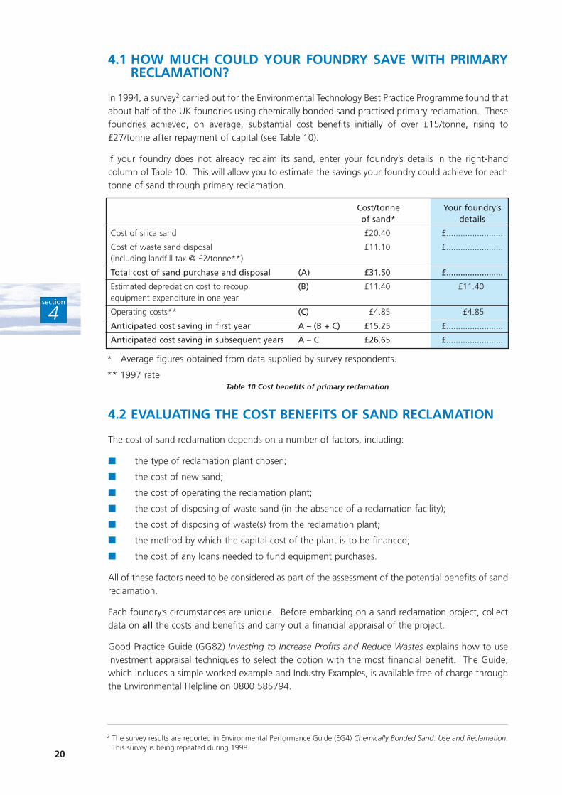
In 1994, a survey2 carried out for the Environmental Technology Best Practice Programme found thatabout half of the UK foundries using chemically bonded sand practised primary reclamation. Thesefoundries achieved, on average, substantial cost benefits initially of over £15/tonne, rising to£27/tonne after repayment of capital (see Table 10).
If your foundry does not already reclaim its sand, enter your foundry’s details in the right-handcolumn of Table 10. This will allow you to estimate the savings your foundry could achieve for eachtonne of sand through primary reclamation.
4.2 EVALUATING THE COST BENEFITS OF SAND RECLAMATION
The cost of sand reclamation depends on a number of factors, including:
■ the type of reclamation plant chosen;
■ the cost of new sand;
■ the cost of operating the reclamation plant;
■ the cost of disposing of waste sand (in the absence of a reclamation facility);
■ the cost of disposing of waste(s) from the reclamation plant;
■ the method by which the capital cost of the plant is to be financed;
■ the cost of any loans needed to fund equipment purchases.
All of these factors need to be considered as part of the assessment of the potential benefits of sandreclamation.
Each foundry’s circumstances are unique. Before embarking on a sand reclamation project, collectdata on all the costs and benefits and carry out a financial appraisal of the project.
Good Practice Guide (GG82) Investing to Increase Profits and Reduce Wastes explains how to useinvestment appraisal techniques to select the option with the most financial benefit. The Guide,which includes a simple worked example and Industry Examples, is available free of charge throughthe Environmental Helpline on 0800 585794.
Cost/tonne Your foundry’s of sand* details
Cost of silica sand £20.40 £........................
Cost of waste sand disposal £11.10 £........................(including landfill tax @ £2/tonne**)
Total cost of sand purchase and disposal (A) £31.50 £........................
Estimated depreciation cost to recoup (B) £11.40 £11.40equipment expenditure in one year
Operating costs** (C) £4.85 £4.85
Anticipated cost saving in first year A – (B + C) £15.25 £........................
Anticipated cost saving in subsequent years A – C £26.65 £........................
* Average figures obtained from data supplied by survey respondents.
** 1997 rateTable 10 Cost benefits of primary reclamation
2 The survey results are reported in Environmental Performance Guide (EG4) Chemically Bonded Sand: Use and Reclamation.This survey is being repeated during 1998.
4.3 EXAMPLE COST SAVINGS
The two examples below show the cost savings and payback achieved by two UK foundries. Theirapplicability to other foundries will, of course, depend on the technical requirements and the levelof reclamation achievable. The examples use the average cost of silica sand and waste sand disposalgiven in Table 10, and assume a landfill tax rate of £2/tonne.
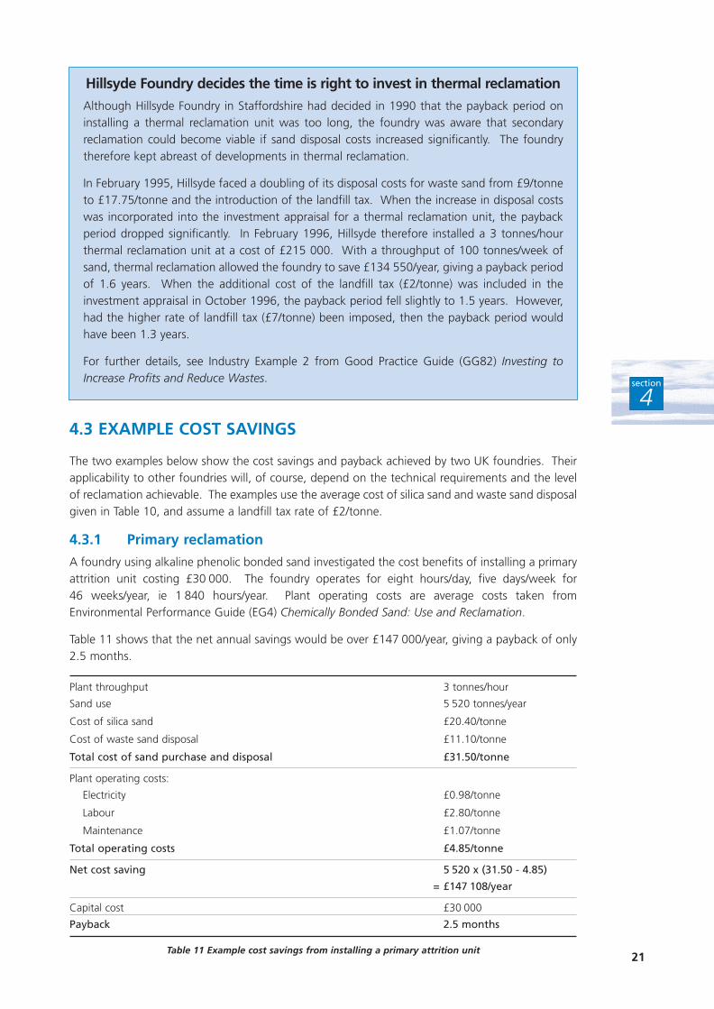
4.3.1 Primary reclamation
A foundry using alkaline phenolic bonded sand investigated the cost benefits of installing a primaryattrition unit costing £30 000. The foundry operates for eight hours/day, five days/week for 46 weeks/year, ie 1 840 hours/year. Plant operating costs are average costs taken fromEnvironmental Performance Guide (EG4) Chemically Bonded Sand: Use and Reclamation.
Table 11 shows that the net annual savings would be over £147 000/year, giving a payback of only2.5 months.
Plant throughput 3 tonnes/hour
Sand use 5 520 tonnes/year
Cost of silica sand £20.40/tonne
Cost of waste sand disposal £11.10/tonne
Total cost of sand purchase and disposal £31.50/tonne
Plant operating costs:
Electricity £0.98/tonne
Labour £2.80/tonne
Maintenance £1.07/tonne
Total operating costs £4.85/tonne
Net cost saving 5 520 x (31.50 - 4.85)
= £147 108/year
Capital cost £30 000
Payback 2.5 months
Table 11 Example cost savings from installing a primary attrition unit21
section
4
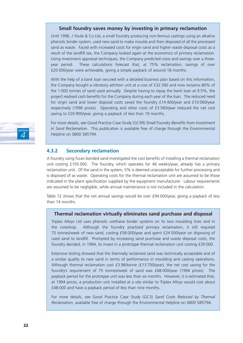
Hillsyde Foundry decides the time is right to invest in thermal reclamation
Although Hillsyde Foundry in Staffordshire had decided in 1990 that the payback period oninstalling a thermal reclamation unit was too long, the foundry was aware that secondaryreclamation could become viable if sand disposal costs increased significantly. The foundrytherefore kept abreast of developments in thermal reclamation.
In February 1995, Hillsyde faced a doubling of its disposal costs for waste sand from £9/tonneto £17.75/tonne and the introduction of the landfill tax. When the increase in disposal costswas incorporated into the investment appraisal for a thermal reclamation unit, the paybackperiod dropped significantly. In February 1996, Hillsyde therefore installed a 3 tonnes/hourthermal reclamation unit at a cost of £215 000. With a throughput of 100 tonnes/week ofsand, thermal reclamation allowed the foundry to save £134 550/year, giving a payback periodof 1.6 years. When the additional cost of the landfill tax (£2/tonne) was included in theinvestment appraisal in October 1996, the payback period fell slightly to 1.5 years. However,had the higher rate of landfill tax (£7/tonne) been imposed, then the payback period wouldhave been 1.3 years.
For further details, see Industry Example 2 from Good Practice Guide (GG82) Investing toIncrease Profits and Reduce Wastes.
22
section
4
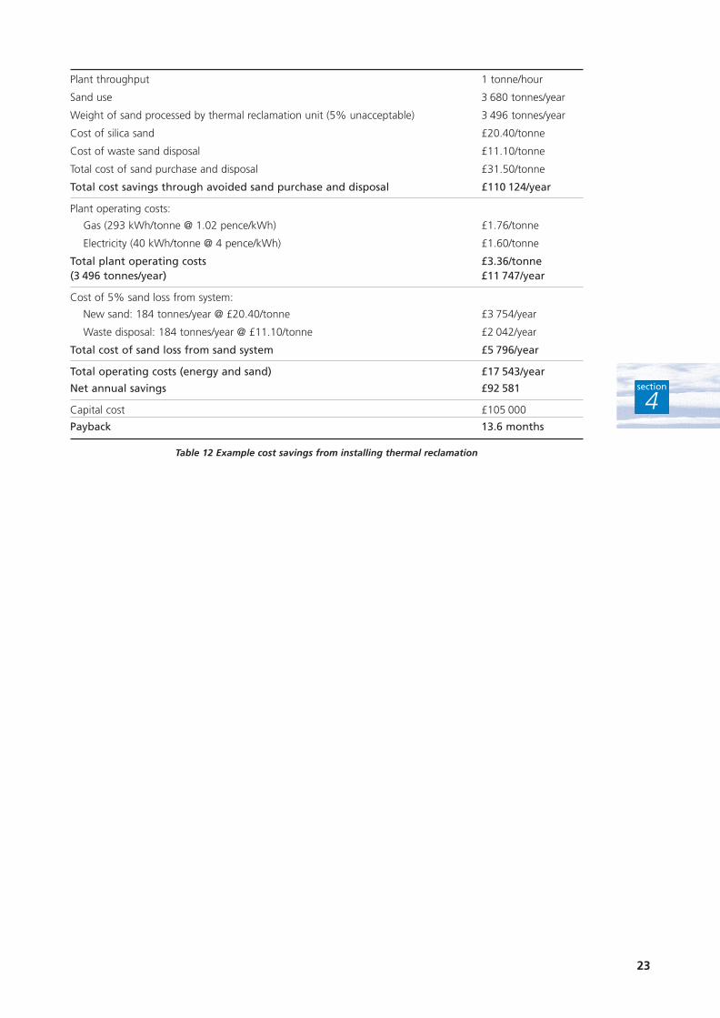
4.3.2 Secondary reclamation
A foundry using furan bonded sand investigated the cost benefits of installing a thermal reclamationunit costing £105 000. The foundry, which operates for 46 weeks/year, already has a primaryreclamation unit. Of the sand in the system, 5% is deemed unacceptable for further processing andis disposed of as waste. Operating costs for the thermal reclamation unit are assumed to be thoseindicated in the plant specification supplied by the equipment manufacturer. Labour requirementsare assumed to be negligible, while annual maintenance is not included in the calculation.
Table 12 shows that the net annual savings would be over £94 000/year, giving a payback of lessthan 14 months.
22
Small foundry saves money by investing in primary reclamation
Until 1996, J Youle & Co Ltd, a small foundry producing non-ferrous castings using an alkalinephenolic binder system, used new sand to make moulds and then disposed of all the processedsand as waste. Faced with increased costs for virgin sand and higher waste disposal costs as aresult of the landfill tax, the Company looked again at the economics of primary reclamation.Using investment appraisal techniques, the Company predicted costs and savings over a three-year period. These calculations forecast that, at 75% reclamation, savings of over£20 000/year were achievable, giving a simple payback of around 18 months.
With the help of a bank loan secured with a detailed business plan based on this information,the Company bought a vibratory attrition unit at a cost of £32 390 and now reclaims 80% ofthe 1 000 tonnes of sand used annually. Despite having to repay the bank loan at 9.5%, theproject realised cash benefits for the Company during each year of the loan. The reduced needfor virgin sand and lower disposal costs saved the foundry £14 400/year and £10 060/yearrespectively (1996 prices). Operating and other costs of £3 560/year reduced the net costsaving to £20 900/year, giving a payback of less than 19 months.
For more details, see Good Practice Case Study (GC99) Small Foundry Benefits from Investmentin Sand Reclamation. This publication is available free of charge through the EnvironmentalHelpline on 0800 585794.
Thermal reclamation virtually eliminates sand purchase and disposal
Triplex Alloys Ltd uses phenolic urethane binder systems on its two moulding lines and in the coreshop. Although the foundry practised primary reclamation, it still required75 tonnes/week of new sand, costing £58 000/year and spent £24 500/year on disposing ofused sand to landfill. Prompted by increasing sand purchase and waste disposal costs, thefoundry decided, in 1994, to invest in a prototype thermal reclamation unit costing £30 000.
Extensive testing showed that the thermally reclaimed sand was technically acceptable and ofa similar quality to new sand in terms of performance in moulding and casting operations.Although thermal reclamation cost £3.96/tonne (£13 700/year), the net cost saving for thefoundry’s requirement of 75 tonnes/week of sand was £68 000/year (1994 prices). Thepayback period for the prototype unit was less than six months. However, it is estimated that,at 1994 prices, a production unit installed at a site similar to Triplex Alloys would cost about£48 000 and have a payback period of less than nine months.
For more details, see Good Practice Case Study (GC3) Sand Costs Reduced by ThermalReclamation, available free of charge through the Environmental Helpline on 0800 585794.
23
section
4
Plant throughput 1 tonne/hour
Sand use 3 680 tonnes/year
Weight of sand processed by thermal reclamation unit (5% unacceptable) 3 496 tonnes/year
Cost of silica sand £20.40/tonne
Cost of waste sand disposal £11.10/tonne
Total cost of sand purchase and disposal £31.50/tonne
Total cost savings through avoided sand purchase and disposal £110 124/year
Plant operating costs:
Gas (293 kWh/tonne @ 1.02 pence/kWh) £1.76/tonne
Electricity (40 kWh/tonne @ 4 pence/kWh) £1.60/tonne
Total plant operating costs £3.36/tonne(3 496 tonnes/year) £11 747/year
Cost of 5% sand loss from system:
New sand: 184 tonnes/year @ £20.40/tonne £3 754/year
Waste disposal: 184 tonnes/year @ £11.10/tonne £2 042/year
Total cost of sand loss from sand system £5 796/year
Total operating costs (energy and sand) £17 543/year
Net annual savings £92 581
Capital cost £105 000
Payback 13.6 months
Table 12 Example cost savings from installing thermal reclamation
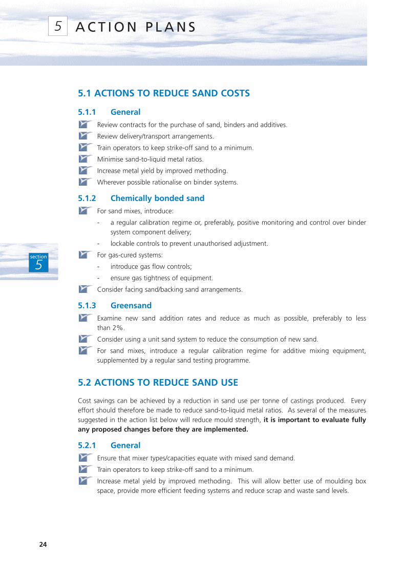
5.1 ACTIONS TO REDUCE SAND COSTS
5.1.1 General
Review contracts for the purchase of sand, binders and additives.
Review delivery/transport arrangements.
Train operators to keep strike-off sand to a minimum.
Minimise sand-to-liquid metal ratios.
Increase metal yield by improved methoding.
Wherever possible rationalise on binder systems.
5.1.2 Chemically bonded sand
For sand mixes, introduce:
- a regular calibration regime or, preferably, positive monitoring and control over bindersystem component delivery;
- lockable controls to prevent unauthorised adjustment.
For gas-cured systems:
- introduce gas flow controls;
- ensure gas tightness of equipment.
Consider facing sand/backing sand arrangements.
5.1.3 Greensand
Examine new sand addition rates and reduce as much as possible, preferably to less than 2%.
Consider using a unit sand system to reduce the consumption of new sand.
For sand mixes, introduce a regular calibration regime for additive mixing equipment,supplemented by a regular sand testing programme.
5.2 ACTIONS TO REDUCE SAND USE
Cost savings can be achieved by a reduction in sand use per tonne of castings produced. Everyeffort should therefore be made to reduce sand-to-liquid metal ratios. As several of the measuressuggested in the action list below will reduce mould strength, it is important to evaluate fullyany proposed changes before they are implemented.
5.2.1 General
Ensure that mixer types/capacities equate with mixed sand demand.
Train operators to keep strike-off sand to a minimum.
Increase metal yield by improved methoding. This will allow better use of moulding boxspace, provide more efficient feeding systems and reduce scrap and waste sand levels.
24
section
5
A C T I O N P L A N S5
5.2.2 Chemically bonded sand
Minimise sand-to-liquid metal ratios by:
- Using shaped boxes that follow casting contours more closely.
- Blocking-in box corners (where appropriate) to reduce the amount of sand required.
- The judicious use of ‘loose pieces’ and inserts to hollow out the mould in non-criticalareas.
- Reviewing wall thickness and, in particular, the amount of sand beneath the casting. Theuse of reinforcing wires or bars may be preferable to excessively thick walls.
- Incorporating lumps of waste sand as a backing material to fill space and reduce binderconsumption. An alternative is to use metal spheres cast with metal that would normallybe pigged. These spheres must, however, be confined to sand away from the pattern face.
5.2.3 Greensand
Consider changing to a unit sand system as this uses less new sand than a facingsand/backing sand approach. However, steel foundries should review casting quality as wellas mixed sand properties.
Use any additives in the most cost-effective manner as additive costs are significant, even inthe relatively small quantities used.
Check the quality of sand at the greensand mixer regularly, either manually in smalloperations or using automatic sensors to check each mix in continuous operations.
5.3 ACTIONS TO IMPROVE WASTE SAND MANAGEMENT
Evaluate primary reclamation techniques (if not already adopted).
Optimise primary reclamation.
Consider secondary reclamation where primary reclamation is already used.
Use the highest amount of reclaimed sand possible in the sand mix.
Ensure hopper capacity is sufficient to enable the maximum use of reclaimed sand.
When both primary and secondary reclamation have been optimised, examine options forbeneficial re-use of the waste sand (see Section 6).
Ensure there is a convenient way to remove waste from the sand system.
Segregate waste sand classified as inactive for the purposes of the landfill tax from generalwaste such as wood, paper and packaging that attracts the higher rate of tax. Any mixedloads of unsegregated wastes will also be charged at the higher rate.
Review waste handling to ensure that materials classified as inactive do not becomecontaminated with hazardous materials, eg many binder chemicals. All of such waste willthen have to be disposed of - at a much higher cost - as special waste.
5.4 PRACTICAL STEPS FOR BEST PRACTICE IN SAND MANAGEMENTAND RECLAMATION
Keep foreign objects and other contaminants out of the sand system as they will ultimatelyclog the distribution system, leading to downtime.
Reduce binder additions to the optimum level, making use of supporting frames if necessary.Computer-controlled binder systems allow foundries to operate at lower binder levels, whilemaintaining adequate mould strength.
25
section
5
If the moulds are large enough, consider facing with a relatively high binder content sand andbacking with a sand with a lower binder level. In this way, the two-thirds of the sand thatreceives the least heat input contains less binder to remove during reclamation. This approachworks best when a zero retention mixer is used.
Consider reducing the overall amount of binder used per mould by filling space well awayfrom the pattern face with lower quality material, eg:
- Place lumps of waste sand (up to 5 cm across) from previous moulds in the corners ofthe moulding box.
- Gather up core butts and other ‘lumps’ from a mechanical attrition unit or even theshakeout and throw this material into the box as the bonded sand is applied.
- Put 3.5 - 7.5 cm steel spheres (cast with surplus metal or pig metal) in the mould. In avibratory shakeout unit, these spheres help break the mould apart and also act as‘hammers’ in breaking up sand lumps on the vibrating deck. Lump reduction is speededup and the spheres can be recycled. However, care should be taken not to ‘over-vibrate’during compaction or the spheres will sink to the parting line.
Reduce sand-to-metal ratios by removing unnecessary sand. This may include:
- ‘cutting corners’, using loose pieces, not moulding the cope to the full height of the box,or using inserts to hollow out the mould in non-critical areas;
- using wires and rods for judicious reinforcement rather than thicker walls created byadding thicker sand sections;
- reviewing the thickness of the bottom mould to avoid the use of deeper drags thannecessary.
When implementing these practices, be sure to add generous radii; sharp corners will concentratestresses - both thermally induced and from handling - causing the mould to crack, sometimesprematurely.
Delay shakeout for as long as practicable to achieve maximum burn-out of the binder; self-reclamation is the most effective of all reclamation techniques.
Consider breaking the moulds in a conveyor, leaving the castings on top of the sand to cooland thus release heat into the sand below. This minimises shakeout damage and helps burnout more binder. However, a way of recovering the ‘burnt’ sand and adequate sand coolingcapacity in the reclamation plant are required.
Do not overload the reclamation unit as all reclamation systems work within a reasonablytight loading range. Use load cells or measure motor current to sense when to add moresand, and then add it incrementally. If necessary, use surge hoppers.
Do not overlook the need for anti-segregation devices in the sand system to maintain boththe sand grain size distribution and minimum binder additions.
Pay particular attention to the classification and de-dusting of sand in the reclamationprocess. Ensure optimum performance by:
- Using a dedicated and properly maintained dust collector.
- Monitoring pressure drops and air flow rates.
- Using control charts to record the waste removed from the dust collector in terms ofweight of dust/tonne of sand processed. Fluctuations and/or trends will reflect operationalchanges and allow corrective action to be taken before a major problem arises.
If you require a reclamation plant with a throughput of more than 5 tonnes/hour, considerinstalling two or more smaller units, running in parallel, rather than one larger one. Inaddition to possible cost advantages, this will allow production to continue in the event of ashutdown in one of the units. It also allows for the operation of a single unit during periodswhen the foundry is operating at less than full capacity.
26
section
5
Pay attention to plant design and installation, eg:
- Install large bolt doors to allow access to the ductwork.
- Ensure that there are aisles that can accommodate the containers needed if the unit hasto be emptied.
- Monitor areas of potential sand build-up in the ductwork, eg low pressure points. Thesecan fill with sand, sometimes causing them to collapse.
Move sand around the foundry carefully, eg:
- use air slides instead of elevators, and pneumatic transporters rather than conveyor belts;
- use dense phase pneumatic sand transporters that do not degrade the sand significantlyas it is moved from the reclamation plant to its point of use;
- design units with fool-proof transfer points to keep sand in the system and off the floor;
- enclose the system to prevent losses and keep work areas clean - in the long run this ischeaper than using brooms and shovels.
5.5 ACTIONS TO IMPROVE SAND STORAGE
Correct storage of sand is important to ensure that the sand supplied to the mixers is of a consistentquality.
5.5.1 General
Keep silos sealed and waterproof to prevent ingress of water. Excessive moisture in sand canresult in delayed strip times, mould distortion on stripping and, in extreme cases, preventionof curing. Phenolic urethane systems are particularly sensitive to these effects.
Protect storage facilities, including internal hoppers, from contamination by foreign objectsthat may obstruct the flow. Any delay in detecting contamination can lead to a productionrun of sub-standard moulds or cores.
Check the effectiveness of the dust removal system by measuring the quantity collected.Delivered sand contains about 0.5% dust, so about 5 kg of dust should be collected for eachtonne supplied.
5.5.2 Measures to minimise segregation
Whenever sand is moved or handled, there is the potential for segregation to occur. The wider thegrain size distribution within the sand, the more pronounced will be the effect. This is one of thereasons why a narrow spread in grain size is recommended.
Where segregation does occur, the effect on mould and core quality can be considerable. Becausethe sand discharged from the silo will vary in particle size distribution, the effectiveness of binderadditions will change. Finer sands require higher addition rates. Coarse sand is more prone topenetration and erosion by molten metal.
The greatest segregation problems occur where small volumes of sand are discharged, as is the casewith continuous mixers and small batch mixers. With a batch mixer, the result will be the productionof an occasional bad batch of sand. With continuous mixers, the result will be a striated mould orcore, containing layers of strong and weak sand.
Filters are often positioned on top of silos to enable the collected dust to be discharged directly backinto the silo, eliminating the need for handling and disposal. However, this practice creates a majorsegregation problem as a layer of fines is deposited in the silo every time the filter is shaken down.To avoid segregation, filters should either be positioned below the silo or be designed to permitdischarge to a dust waste collection bin.
27
section
5
Hopper design
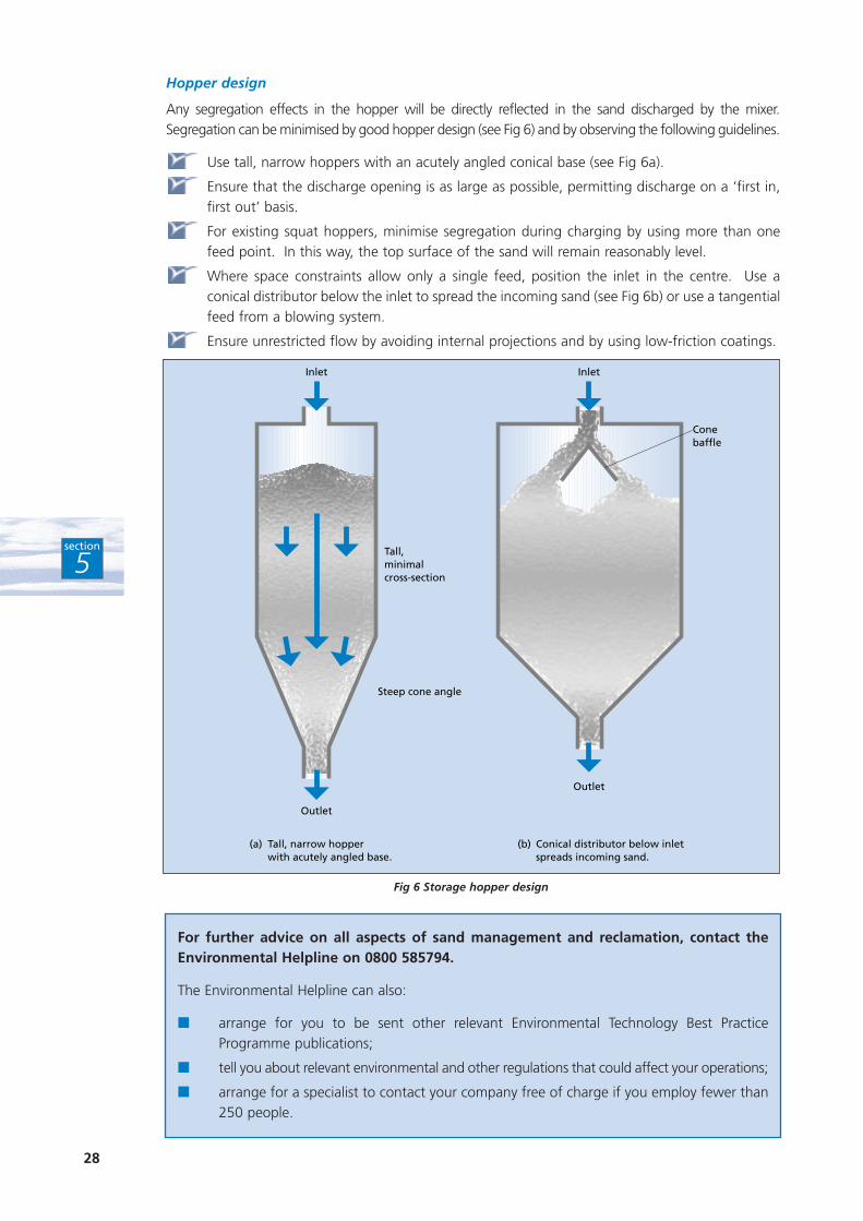
Any segregation effects in the hopper will be directly reflected in the sand discharged by the mixer.Segregation can be minimised by good hopper design (see Fig 6) and by observing the following guidelines.
Use tall, narrow hoppers with an acutely angled conical base (see Fig 6a).
Ensure that the discharge opening is as large as possible, permitting discharge on a ‘first in,first out’ basis.
For existing squat hoppers, minimise segregation during charging by using more than onefeed point. In this way, the top surface of the sand will remain reasonably level.
Where space constraints allow only a single feed, position the inlet in the centre. Use aconical distributor below the inlet to spread the incoming sand (see Fig 6b) or use a tangentialfeed from a blowing system.
Ensure unrestricted flow by avoiding internal projections and by using low-friction coatings.
28
section
5
Fig 6 Storage hopper design
Inlet Inlet
Outlet
Outlet
Tall,minimalcross-section
Steep cone angle
Conebaffle
(a) Tall, narrow hopper with acutely angled base.
(b) Conical distributor below inletspreads incoming sand.
For further advice on all aspects of sand management and reclamation, contact theEnvironmental Helpline on 0800 585794.
The Environmental Helpline can also:
■ arrange for you to be sent other relevant Environmental Technology Best PracticeProgramme publications;
■ tell you about relevant environmental and other regulations that could affect your operations;
■ arrange for a specialist to contact your company free of charge if you employ fewer than250 people.
Even after primary and secondary reclamation has been optimised, a foundry may still be left withsome waste sand. However, the beneficial re-use of waste sand and other foundry by-products isattracting increasing interest in the UK.
Arrangements for beneficial re-use vary according to the foundry’s location and circumstances, theparticular by-product, availability, and the volume involved. The main types of arrangement are:
■ one-to-one, ie an agreement between the foundry and a single local user;
■ many-to-one, ie material is collected by a large end user from a number of foundries;
■ all-for-one, ie co-operation between a group of foundries in an area with a highconcentration of foundries, to supply one or more users.
The various applications for the re-use of waste sand are increasingly providing ways in whichfoundries - small as well as large - can reduce their waste disposal costs and achieve other benefits.Other foundry by-products, eg metallic slags and spent refractories, may also be suitable forbeneficial re-use.
6.1 POSSIBLE APPLICATIONS FOR THE RE-USE OF WASTE SAND
6.1.1 Waste sand re-use in the manufacture of asphalt
Both chemically bonded sand and greensand can be used in the manufacture of hot rolled asphalt(HRA) and macadam. The following Case Study describes the savings made by a greensand foundryand an asphalt manufacturer in a recent collaborative venture.
29
section
6
B E N E F I C I A L R E - U S E O FW A S T E S A N D
6
Waste sand sets scene for profitable partnership
Precision Disc Castings Ltd (PDC), a greensand foundry producing brake discs for theautomotive industry, uses recycled sand to make moulds. However, PDC still has to buyapproximately 10 000 tonnes/year of virgin sand to make cores because the recycled sand isnot of suitable quality. To maintain the balance of the sand system, an equivalent amount ofused sand, fines and dust was sent to landfill, at a cost of around £100 000/year. However,when PDC examined the possibility of installing a sand reclamation system, it found that thisoption was not economic for its site.
PDC therefore approached a local company, Tarmac Quarry Products Ltd, with a proposal toreplace part of the fine aggregate used in asphalt manufacture with spent greensand.Following a feasibility study and operational testing, full-scale production of asphalt usingfoundry greensand began in March 1997. Minor modifications were necessary at both plants.Tests have shown that the quality of Tarmac’s products is unaffected by using foundrygreensand and that the products meet all relevant BSI standards.
Both companies have achieved significant net cost savings, with reduced waste sand disposalcosts for PDC and reduced raw material costs for Tarmac. In addition, there are environmentalbenefits through a reduced need for quarrying, landfill and raw material transportation. Table 13shows the savings, costs and payback achieved by PDC and Tarmac re-using 9 000 tonnes ofgreensand per year.
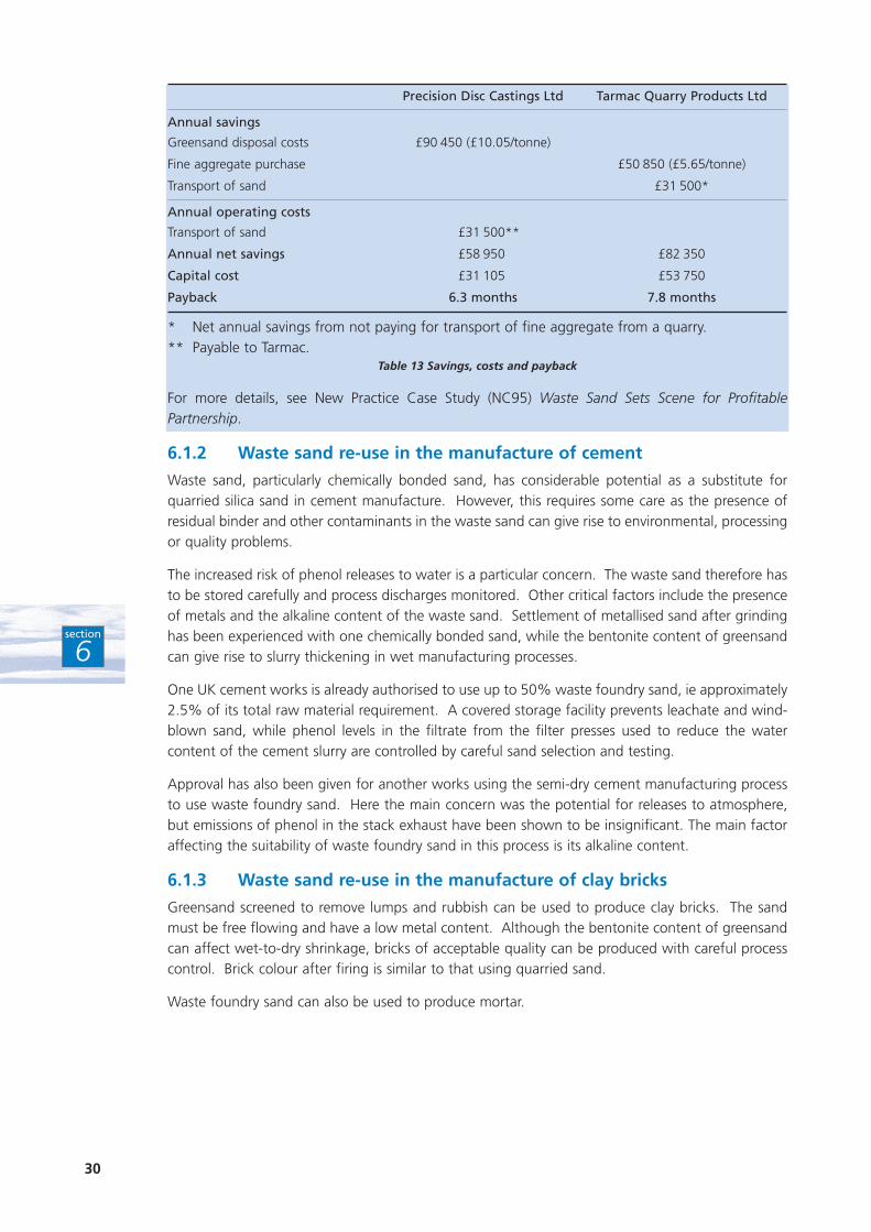
Precision Disc Castings Ltd Tarmac Quarry Products Ltd
Annual savings
Greensand disposal costs £90 450 (£10.05/tonne)
Fine aggregate purchase £50 850 (£5.65/tonne)
Transport of sand £31 500*
Annual operating costs
Transport of sand £31 500**
Annual net savings £58 950 £82 350
Capital cost £31 105 £53 750
Payback 6.3 months 7.8 months
* Net annual savings from not paying for transport of fine aggregate from a quarry.** Payable to Tarmac.
Table 13 Savings, costs and payback
For more details, see New Practice Case Study (NC95) Waste Sand Sets Scene for ProfitablePartnership.
6.1.2 Waste sand re-use in the manufacture of cement
Waste sand, particularly chemically bonded sand, has considerable potential as a substitute forquarried silica sand in cement manufacture. However, this requires some care as the presence ofresidual binder and other contaminants in the waste sand can give rise to environmental, processingor quality problems.
The increased risk of phenol releases to water is a particular concern. The waste sand therefore hasto be stored carefully and process discharges monitored. Other critical factors include the presenceof metals and the alkaline content of the waste sand. Settlement of metallised sand after grindinghas been experienced with one chemically bonded sand, while the bentonite content of greensandcan give rise to slurry thickening in wet manufacturing processes.
One UK cement works is already authorised to use up to 50% waste foundry sand, ie approximately2.5% of its total raw material requirement. A covered storage facility prevents leachate and wind-blown sand, while phenol levels in the filtrate from the filter presses used to reduce the watercontent of the cement slurry are controlled by careful sand selection and testing.
Approval has also been given for another works using the semi-dry cement manufacturing processto use waste foundry sand. Here the main concern was the potential for releases to atmosphere,but emissions of phenol in the stack exhaust have been shown to be insignificant. The main factoraffecting the suitability of waste foundry sand in this process is its alkaline content.
6.1.3 Waste sand re-use in the manufacture of clay bricks
Greensand screened to remove lumps and rubbish can be used to produce clay bricks. The sandmust be free flowing and have a low metal content. Although the bentonite content of greensandcan affect wet-to-dry shrinkage, bricks of acceptable quality can be produced with careful processcontrol. Brick colour after firing is similar to that using quarried sand.
Waste foundry sand can also be used to produce mortar.
30
section
6

6.1.4 Waste sand re-use as aggregate in road construction
Use of waste foundry sand as a substitute for natural aggregate in road construction has a numberof economic and environmental benefits. However, sand is not a conventional road pavementconstruction material and requires some treatment to achieve acceptable mechanical properties.Sand lacks the stiffness and strength of conventional crushed aggregate and, if it gets wet, will tendto become unstable (visible as rutting in the road pavement).
Strategies for using waste foundry sand in road pavement construction usually involve washing toremove fines and adding a small amount of binder, eg cement or cement kiln dust. Use of foundrysand tends to be restricted to lower pavement levels where the stress is less and to areas where sub-drainage can be provided. Contamination of surface water and groundwater from substancesleached from the waste sand has been a concern although limited experience suggests that it is nota problem. Use of binders to reduce permeability as well as to increase mechanical strength isregarded as the optimum treatment method.
6.1.5 Waste sand re-use in ceramic tile production
Waste foundry sand is one of a range of industrial wastes suitable for use in a new ceramic tiletechnology developed in Italy. Savings in raw material costs of over 50% are claimed compared tothe cost of conventional clay materials for ceramic tile production. Wear-resistant floor tiles withspecifications equivalent to porcelain are now available.
6.1.6 Waste sand re-use in horticulture
Waste sand has a number of potential uses in horticultural applications, eg as a component ofpotting compost, as a top dressing to promote plant growth, and for landscaping.
The main barrier to the use of waste foundry sand in horticultural applications is concern aboutmetals and other contaminants that could affect plant growth or enter the food chain. However,preliminary results from experiments in the UK suggest that use of greensand does not adverselyaffect the growth of five indicator crops, ie tomatoes, French beans, maize, barley and oilseed rape.The pH or contaminants present in the greensand may be responsible for the slightly slowergermination rates and initial plant growth observed in these experiments compared to a control soil.The nutrient content (phosphorus, potassium and magnesium) of waste sand proved beneficial togrowth and levels of metals in these experiments were not regarded as a problem. Experiments arealso being performed using furan bonded sand, resin shell sand and alkaline phenolic bonded sand.
In the USA, waste sand has been successfully used as a plant growth media for nursery productionof roses, trees, shrubs and garden annuals. A mixture of 60% top soil, 30% foundry sand and 10%composted garden waste has reportedly produced better results than standard field soil. Researchalso found that greenhouse geraniums grow as well, or better, in potting mixtures containing wastefoundry sand than in control mixtures. Tests indicate that better plant growth is obtained withmixtures of 50% soil and 50% foundry sand than with 100% foundry sand.
Landscaping applications generally use greensand. However, large volumes of waste sand - freefrom rubbish and metals - are required. Phenol and metal leaching are particular problem areas.
The demand for waste foundry sand for top dressing and other horticultural applications can beseasonal.
31
section
6
6.1.7 Waste sand re-use to improve soil drainage
Foundry greensand is currently being evaluated in the USA as a method of permanently modifyingthe surface texture of poorly drained agricultural soils. Excess surface water on poorly drainedfarmland with a high clay content often leads to delays in spring planting, with resulting problemsat harvest time. The potential exists to use large amounts of spent foundry sand to reduce the claycontent of such soils from 28 - 40% to about 25%. This would enable crop planting to startsignificantly earlier.
Crop yields and the metal content of plants grown on sample plots were similar to those from untreatedcontrol plots. Experiments to determine the optimum amount of sand that can be applied are currentlybeing performed. Sand will be applied over a number of years to alter soil properties gradually.
Application to the fields can be carried out directly from flat-bed trucks and no prior processing ofthe waste sand is required.
6.1.8 Other opportunities to re-use waste foundry sand
These include:
■ as hardcore or backfill;
■ concrete blocks;
■ landfill permanent lining and daily cover;
■ roofing felt;
■ glass wool production;
■ waste vitrification.
32
section
6

The Environmental Technology Best Practice Programme is a joint Department of Trade and Industry
and Department of the Environment, Transport and the Regions programme. It is managed by
AEA Technology plc through ETSU and the National Environmental Technology Centre.
The Programme offers free advice and information for UK businesses and promotes
environmental practices that:
■ increase profits for UK industry and commerce;
■ reduce waste and pollution at source.
To find out more about the Programme please call the Environmental Helpline on freephone
0800 585794. As well as giving information about the Programme, the Helpline has access to
a wide range of environmental information. It offers free advice to UK businesses on technical
matters, environmental legislation, conferences and promotional seminars. For smaller
companies, a free counselling service may be offered at the discretion of the Helpline Manager.
FOR FURTHER INFORMATION, PLEASE CONTACT THE ENVIRONMENTAL HELPLINE
0800 585794e-mail address: [email protected]
world wide web: http://www.etsu.com/etbpp/