environmental electromagnetic fields: interference with...
TRANSCRIPT

Environmental electromagnetic fields: interference with cardiac pacemakers and implantable cardioverter-defibrillators
People and WorkResearch Reports 103
Maria Tiikkaja
Environmental electrom
agnetic fields: interference with cardiac pacem
akers and implantable cardioverter-defibrillators
Tiikkaja M.
The risk of electromagnetic interference (EMI) with cardiac pacemakers and implantable cardioverter-defibrillators (ICDs) is of increasing concern in occupational environments. The number of workers with a pacemaker or ICD is growing rapidly. Knowledge is still insufficient concerning sources of EMI and the susceptibility of pacemakers and ICDs to electromagnetic fields (EMFs). In workplaces with strong EMFs, employees are often required to change tasks or retire after receiving a pacemaker/ICD. This study investigates the occurrence of EMI with pacemakers and ICDs in different magnetic fields and occupational environments and estimates potential EMF risks for an employee returning to work after a pacemaker/ICD implantation.
103
ISBN 978-952-261-418-6
Orders:Finnish Institute of Occupational HealthTopeliuksenkatu 41 a AFI-00250 HelsinkiFinland
Fax +358-9 477 5071E-mail [email protected]
ISBN 978-952-261-418-6 (paperback)ISBN 978-952-261-419-3 (PDF)
ISSN-L 1237-6183ISSN 1237-6183
Cover picture: Maria Tiikkaja
VPVP
VP
VPVP
VP( VS ) ( VS ) ( VS ) ( VS ) VS VS VS ( VS ) ( VS ) ( VS ) ( VS ) VS ( VS ) ( VS ) ( VS ) ( V VS VS VS VS ( VS ) ( VS ) ( VS ) ( VS ) ( VS ) ( VS ) VS ( VS ) ( VS ) ( VS ) ( VS ) ( VS ) ( VS ) ( VS ) ( VS ) ( VS ) ( VS ) VS VS VS VS ( VS ) VS VS VS VS

People and Work
Editor in chief Harri Vainio
Scientific editors Irja Kandolin Timo Kauppinen Kari Kurppa Anneli Leppänen Hannu Rintamäki Riitta Sauni
Editor Virve Mertanen
Address Finnish Institute of Occupational Health Topeliuksenkatu 41 a A FI-00250 Helsinki Tel. +358-30 4741 Fax +358-9 477 5071 www.ttl.fi
Layout Mari Pakarinen / Juvenes Print Cover picture Maria Tiikkaja
ISBN 978-952-261-418-6 (paperback) ISBN 978-952-261-419-3 (PDF) ISSN-L 1237-6183 ISSN 1237-6183
Press Suomen Yliopistopaino Oy – Juvenes Print, Tampere 2014

Environmental electromagnetic fields: interference with cardiac pacemakers and implantable cardioverter-defibrillators
Maria Tiikkaja
People and Work Research Reports 103
Finnish Institute of Occupational Health Helsinki 2014

Maria Tiikkaja
author’s address: Finnish institute of Occupational HealthSafety of Technologies and ProtectionTopeliuksenkatu 41 a a00250 Helsinki, Finlandemail: [email protected]
Supervisors: research Professor Maila Hietanen, PhD Finnish institute of Occupational Health Safety of Technologies and Protection Topeliuksenkatu 41 a a 00250 Helsinki, Finland email: [email protected]
Professor jukka juutilainen, PhD University of Eastern Finland Department of Environmental Science P.O. Box 1627 70211 kuopio, Finland email: [email protected]
Reviewers: associate Professor kjell Hansson Mild, DSc (Tech.) Umeå University Department of radiation Sciences SE-901 87 Umeå, Sweden email: [email protected]
research Professor kari jokela, DSc (Tech.) STUk-radiation and Nuclear Safety authority PL 14 00881 Helsinki, Finland email: [email protected] Opponent: Professor Fabriziomaria Gobba, MD, PhD University of Modena and reggio Emilia Department of Public Health Sciences Via Campi 287 41125 Modena, italy email: [email protected]

3
AbstrAct
BackgroundThe risk of electromagnetic interference (EMI) to implanted cardiac rhythm devices such as pacemakers and cardioverter-defibrillators (ICDs) is causing increasing concern and problems in occupational environ-ments. As the mean age of people receiving their first pacemaker or ICD is falling, the number of working-age people with these devices is growing. A major concern in workplaces is that all possible sources of EMI are not yet fully known.
The aims of this study were to find threshold magnetic field intensi-ties for EMI with several commonly-used pacemaker and ICD models tested in vitro and to evaluate in vivo the susceptibility of pacemakers and ICDs to controlled electromagnetic fields (EMFs) generated in the laboratory. Volunteers with a pacemaker or ICD were also exposed to EMFs emitted by some electromagnetic applications found in real work environments in order to detect possible pacemaker/ICD malfunction. In addition, a case of an ICD EMI caused by a laptop computer was investigated.
Materials and methodsSixteen pacemakers and 17 ICDs were exposed in vitro to magnetic fields with the frequency range of 2 Hz to 1 kHz produced by a computer-controlled Helmholtz coil system. The magnetic fields used varied in intensity and had sinusoidal, pulse, ramp, and square waveforms. The highest exposure levels were chosen to comply with the occupational exposure reference levels for sinusoidal magnetic fields given by the Inter-national Commission on Non-Ionizing Radiation Protection (ICNIRP)

4
abstract
in 1998. For non-sinusoidal waveforms the peak values were derived from these reference levels.
Eleven volunteers with a pacemaker and 13 with an ICD were ex-posed in vivo to different magnetic fields with frequencies from 2 to 200 Hz using similar waveforms and exposure system as in the in vitro tests. The magnetic flux densities ranged up to 300 µT. The volunteers were also exposed to EMFs emitted by an electronic anti-theft gate, an induction hob, and a metal inert gas (MIG) welding machine. All in vivo tests were performed with bipolar sensing configurations of the pacemakers tested. The pacemakers were tested with two programmed pacing settings: the basic rate programmed low enough to favour the subject’s intrinsic rhythm and high enough to result in 100% pacing. Three of the pacemakers were also tested with unipolar sensing settings. The unipolar pacemakers were programmed to pace with a rate higher than the subject’s intrinsic rhythm. Eleven volunteers with a pacemaker were exposed to EMFs near two mobile phone base stations, in an electric commuter train, and under high voltage transmission lines. In these tests, all pacemakers were programmed to normal clinically selected settings with bipolar sensing and pacing configurations. A case of an ICD EMI with a laptop computer was replicated with the same volunteer and computer.
ResultsMalfunctions caused by the external magnetic fields occurred in six of the pacemakers and 11 of the ICDs tested in vitro. In most exposure situations, there was no EMI with the pacemakers or ICDs at magnetic field levels below the ICNIRP occupational safety limits. However, some frequencies using ramp or square-waveforms interfered with the function of the pacemakers even at levels below ICNIRP limits for public exposure. No EMI occurred with the ICDs below these limits. The occurrence of EMI depended greatly on the waveform, frequency, and intensity of the magnetic field. With the pacemakers, also the sensing configuration affected the occurrence of malfunctions. The pacemakers with unipolar sensing were more susceptible to interference than bipolar ones. In ad-dition, magnetic fields perpendicular to the pacemaker generator and its electrode loops were more likely to cause EMI than parallel ones.

5
abstract
None of the ICDs or pacemakers tested with bipolar sensing set-tings experienced interference in any of the in vivo exposure situations. The three pacemakers tested with unipolar settings were affected by the magnetic fields of the Helmholtz coil, and one of them also by the EAS gate and the welding cable. The induction hob did not interfere with any of the unipolarly programmed pacemakers. The laptop computer EMI with an ICD was successfully replicated in the laboratory. The conversion of the ICD to magnet mode was found to be due to the static magnetic field produced by the hard disk of the laptop computer.
ConclusionPacemakers programmed with unipolar sensing configurations can cause danger to their users in environments with high EMFs, and should be avoided whenever possible. Laptop computers, positioned above an ICD, can cause EMI with the ICD. This interference may convert the ICD to magnet mode which is dangerous because it, temporarily or permanently, stops all tachyarrhythmia detections and therapies on most ICD models.
In the majority of workplaces, EMI with cardiac pacemakers or ICDs is unlikely. Magnetic fields with intensities as high as those used in this study are rare even in industrial working environments. However, an individual risk assessment shall be carried out when an employee returns to work after a pacemaker or ICD implantation.

6
tiivistelmä
Ihmiseen asennettujen sydäntahdistimien riski häiriintyä sähkömag-neettisissa kentissä huolestuttaa ja aiheuttaa ongelmia erilaisissa työym-päristöissä. Koska tahdistimia asennetaan yhä nuoremmille henkilöille, työvoiman ikääntyessä yhä useammalla työntekijällä on tahdistin. Työpaikkojen suuri huolenaihe onkin, ettei kaikkia mahdollisia sähkö-magneettisen häiriön lähteitä vielä tunneta täysin.
Tässä tutkimuksessa pyrittiin määrittämään magneettikentän voimak-kuuden kynnysarvot useiden yleisesti käytettyjen hitaansykkeentahdisti-mien (bradycardia pacemaker) ja rytmihäiriötahdistimien (implantable cardioverter-defibrillator, ICD) sähkömagneettisille häiriöille laboratorio-olosuhteissa. Lisäksi arvioitiin koehenkilöiden tahdistimien herkkyyttä erilaisille laboratoriossa tuotetuille magneettikentille. Koehenkilöitä altistettiin myös todellisissa työympäristöissä käytettävien laitteiden aiheuttamille sähkömagneettisille kentille. Lisäksi tutkittiin tapausta, jossa kannettava tietokone aiheutti häiriötä rytmihäiriötahdistimen toiminnassa.
Kokeessa 16 hitaansykkeen- ja 17 rytmihäiriötahdistinta upotettiin ihmisen kudosten sähköfysiologisia ominaisuuksia vastaavaan suola-liuokseen ja altistettiin erilaisille magneettikentille taajuusalueella 2 Hz–1 kHz. Magneettikentät tuotettiin tietokoneohjatulla kelasysteemillä ja ne vaihtelivat voimakkuudeltaan sekä aaltomuodoltaan. Voimakkuudeltaan korkeimmat altistustasot valittiin yhtä suuriksi kuin Kansainvälisen ionisoimattoman säteilyn komission (International Commission on Non-Ionizing Radiation Protection, ICNIRP) vuonna 1998 vahvistamat työntekijöiden altistumisen viitearvot sinimuotoisille magneettikentille. Muille kun siniaaltokentille johdettiin painotetut huippuarvot näistä viitearvoista.
7
tiivistelmä
Testeihin osallistui 11 koehenkilöä, joilla oli hitaansykkeentahdistin ja 13 henkilöä, joilla oli rytmihäiriötahdistin. Heidät altistettiin 2–200 Hz taajuisille magneettikentille eri magneettivuon tiheyksillä aina 300 µT asti. Altistussysteemi ja aaltomuodot olivat samat kuin pelkkien tah-distimien testauksissa. Koehenkilöt altistettiin myös varashälytinportin, induktiolieden ja MIG-hitsauskaapelin aiheuttamille sähkömagneettisille kentille. Kaikki koehenkilötestit suoritettiin hitaansykkeentahdistimien tunnistuksen ollessa kaksinapaista.
Hitaansykkeentahdistimet testattiin käyttämällä kahta eri tahdistus-asetusta. Ensin tahdistuksen sykeraja ohjelmoitiin riittävän alas, jolloin tahdistin ei tahdistanut sydäntä lainkaan testien aikana. Seuraavaksi tahdistusraja ohjelmoitiin riittävän ylös, jolloin tahdistin tahdisti sydän-tä koko ajan testien aikana. Kolme hitaansykkeentahdistinta testattiin lisäksi myös tunnistukseltaan yksinapaisina. Yksinapaisina testattaessa tahdistimet oli ohjelmoitu tahdistamaan koehenkilön sydäntä koko ajan.
Tutkimuksessa 11 hitaansykkeentahdistimen käyttäjää altistettiin sähkömagneettisille kentille kahden matkapuhelinten tukiaseman lä-heisyydessä, sähköjunassa ja suurjännitejohtojen alla. Näiden testien aikana tahdistimien asetuksia ei muutettu, vaan kaikki tahdistimet olivat ohjelmoituna normaaleille kliinisille asetuksilleen tunnistuksen ja tahdistuksen ollessa kaksinapaisia. Yhden koehenkilön havaitsema rytmihäiriötahdistimen häiriintymistilanne kannettavan tietokoneen läheisyydessä toistettiin saman koehenkilön ja tietokoneen kanssa.
Ulkoisten magneettikenttien aiheuttamia toimintahäiriöitä esiintyi kuudessa hitaansykkeentahdistimessa ja 11 rytmihäiriötahdistimessa, kun laitteet testattiin suolaliuoksessa. Suurimmassa osassa altistustilanteita sähkömagneettisia häiriöitä ei havaittu magneettikentän voimakkuuksien ollessa työntekijöille tarkoitettujen ICNIRP:n viitearvojen alapuolella. Kuitenkin joillain taajuuksilla hitaansykkeentahdistimet häiriintyivät jopa väestön altistumiselle asetettujen viitearvojen alapuolella käytettäessä nopeita kentänvoimakkuuden muutoksia sisältäviä ramppi- tai kantti-aaltoja. Rytmihäiriötahdistimilla ei havaittu toimintahäiriöitä väestön viitearvojen alapuolella.
Sähkömagneettisten häiriöiden esiintyminen riippui suuresti käy-tetyn magneettikentän aaltomuodosta, taajuudesta ja voimakkuudesta. Hitaansykkeentahdistimilla myös tunnistuksen napaisuus vaikutti häiriöiden ilmaantumiseen. Yksinapaiseen tunnistukseen ohjelmoidut

8
tiivistelmä
hitaansykkeentahdistimet olivat herkempiä häiriöille kuin kaksinapaisen tunnistuksen laitteet. Lisäksi sähkömagneettisten häiriöiden todennäköi-syys oli suurempi tahdistinsysteemin (generaattorin ja elektrodijohtojen) muodostaman pinta-alan ollessa kohtisuoraan magneettikenttää vastaan kuin tahdistinsysteemin kanssa samansuuntaisissa kentissä.
Koehenkilöillä tehdyissä kokeissa yksikään rytmihäiriötahdistimista tai kaksinapaisen tunnistuksen hitaansykkeentahdistimista ei häiriinty-nyt missään altistustilanteessa. Kaikki kolme yksinapaisella tunnistuk-sella varustettua hitaansykkeentahdistinta häiriintyivät laboratoriossa tuotetuissa magneettikentissä ja yksi niistä lisäksi varashälytinportin ja hitsauskaapelin läheisyydessä. Induktioliesi ei aiheuttanut häiriöitä yhteenkään yksinapaiseen tahdistimeen. Kannettavan tietokoneen aiheuttama sähkömagneettinen häiriö rytmihäiriötahdistimen toimin-nassa pystyttiin toistamaan laboratoriossa. Tahdistimen siirtyminen magneettitilaan johtui tietokoneen kovalevyn aiheuttamasta staattisesta magneettikentästä.
Tunnistukseltaan yksinapainen ohjelmointi hitaansykkeentahdisti-missa voi aiheuttaa vaaraa ympäristöissä, joissa on voimakkaita sähkö-magneettisia kenttiä. Siksi sitä tulisi välttää aina kun mahdollista. Kan-nettavan tietokoneen käyttö makuuasennossa rytmihäiriötahdistimen päällä aiheutti sähkömagneettista häiriötä tahdistimen toimintaan. Tämä häiriö saattaa siirtää rytmihäiriötahdistimen magneettitilaan, jolloin suu-rimmassa osassa tahdistinmalleista kaikki tahdistimen rytmihäiriöiden tunnistukset ja hoidot loppuvat hetkellisesti tai pysyvästi.
Tässä tutkimuksessa käytetyt varsin suuret magneettikenttien voimak-kuudet ovat harvinaisia jopa teollisissa työympäristöissä. Suurimmassa osassa työpaikoista sydäntahdistimien sähkömagneettinen häiriintyminen on epätodennäköistä. Kuitenkin sydäntahdistimen asennuksen jälkeen on aina tärkeää tehdä yksilöllinen riskinarviointi ennen työntekijän paluuta työtehtäviinsä.

9
list of AbbreviAtions
AAI Atrial sensing and pacingAC Alternating currentAMS Auto mode switchATP Anti-tachycardia pacingbpm Beats per minuteCENELEC European Committee for Electrotechnical Standardiza-
tion (Comité Européen de Normalisation Electrotech-nique)
CRT-D Cardiac resynchronizing therapy implantable cardioverter-defibrillator (biventricular ICD)
CRT-P Cardiac resynchronizing therapy pacemaker (biventricular pacemaker)
DC Direct currentDDD Dual chamber (atrial and ventricular) sensing and pacing
with atrioventricular synchronyDDDR DDD, with a sensor that records a demand for higher
cardiac output and can adjust the heart rate accordinglyDDI Dual chamber (atrial and ventricular) sensing and pacing
without atrium synchronous ventricular pacingDOO Asynchronous atrioventricular sequential pacing (noise
mode)EAS Electronic article surveillanceEC European CouncilECG ElectrocardiographyEGM ElectrogramEMF Electromagnetic field

10
list of AbbreviAtions
EMI Electromagnetic interferenceEN European NormEU European UnionGSM Global System for Mobile CommunicationsFDA Food and Drug Administration of the United StatesICD Implantable cardioverter-defibrillatorICNIRP International Commission on Non-Ionizing Radiation
Protectionin vitro tests Tests performed with an explanded or demo-device pace-
maker/ICD without a human body, using a phantom or body simulator
in vivo tests Volunteer tests performed with an implanted pacemaker/ICD
LVAD Left ventricular assist deviceMIG Metal inert gas (welding)MRI Magnetic resonance imagingNaCl Sodium ChlorideNMES Neuromuscular electric stimulationNMT Nordic Mobile TelephoneRF Radio frequency (100 kHz–300 GHz)RFID Radiofrequency identification readerrms Root-mean-squareRNS Repetitive nerve stimulationRV Right ventricleSAR Specific absorption rateSD Standard deviationSSI Either AAI or VVISSIR Either AAIR or VVIRTENS Transcutaneous electric nerve stimulationTETRA Terrestrial Trunked RadioUMTS Universal Mobile Telecommunication SystemU.S. The United StatesVDD Dual chamber (atrial and ventricular) sensing and ven-
tricular pacingVF Ventricular fibrillationVP Ventricular pacingVS Ventricular sensing

11
list of AbbreviAtions
VT Ventricular tachycardiaVVI Ventricular sensing and pacingVVIR VVI with a sensor that records a demand for higher
cardiac output and can adjust the heart rate accordinglyWHO World Health OrganizationWLAN Wireless local area network

12
list of symbols
A AmpereB Magnetic flux density, in Tesla [T] (1 µT = 10-3 mT =
10-6 T)Bpub ICNIRP reference level for public exposure to sinusoidal
magnetic fields or the maximum peak limit for public exposure to non-sinusoidal magnetic fields, in per cent [%].
Bocc ICNIRP reference level for occupational exposure to sinusoidal magnetic fields or the maximum peak limit for occupational exposure to non-sinusoidal magnetic fields, in per cent [%].
Brms Root-mean-square value of magnetic flux density, in Tesla [T]
c Velocity of light, in metre per second [m/s] (2.998 x 10⁸ m/s in vacuum)
E Electric field strength, in Volt per metre [V/m]f Frequency, in Hertz [Hz]H Magnetic field strength, in Ampere per metre [A/m]J Jouleλ Wavelength, in metre [m]µ Magnetic permeability, in Henry per metre [H/m] (1.26
x 10-6 H/m in vacuum)SAR Specific absorption rate, in Watt per kilogramme [W/kg]V VoltW Watt

13
AcknoWlEdgEMEnTs
This work was carried out at the Finnish Institute of Occupational Health, Helsinki and it was supported financially by the Finnish Work Environment Fund, which I acknowledge gratefully.
I wish to express my deepest gratitude to my principal supervisor Research Professor Maila Hietanen for her guidance, support and friend-ship over the years. I want to thank you for giving me this opportunity and believing in my ability to see it through. I would also like to thank my supervisor Professor Jukka Juutilainen for his advice and support especially during the writing process of the original publications and the thesis.
I am very grateful to the official reviewers of this thesis, Research Professor Kari Jokela and Associate Professor Kjell Hansson Mild for their interest and constructive comments to my manuscript.
In addition, I want to thank my colleague Docent Tommi Alanko for his continuous help and especially his patience and optimism dur-ing this and other work projects. I also wish to express my gratitude to my other co-authors Aapo Aro MD, PhD, Professor Juha Hartikainen, Harri Lindholm MD, PhD, Heli Sistonen MHc, and Professor Lauri Toivonen for their valuable contributions to the original publications. Without your medical expertise and significant collaboration it would not have been possible to conduct this work. This work has been done in collaboration with the Department of Cardiology of the Helsinki University Central Hospital which I acknowledge gratefully. Pacemaker manufacturers Medtronic, St. Jude Medical, and WL-Medical (represent-ing Boston Scientific) and other participant companies are also gratefully acknowledged for consultation and equipment resources. I wish to thank the volunteers who participated in this study. I also want to thank Alice

14
ACKNOWLEDGEMENTS
Lehtinen for the language revision of the original publications included in this theses.
I want to thank my superiors Carita Aschan PhD and Docent Timo Tuomi at the Finnish Institute of Occupational Health for the opportu-nity to work in the field of occupational health and safety. I have really enjoyed these years and hope there will be many more to come. I am also grateful to my co-workers in the Safety of Technologies and Protection team as well as in other parts of our institute. You have made the working athmosphere inspiring and fun and I thank you for that.
I want to sincerely thank my family and friends for all the support and love they have given me during this process. I hope you know how much you mean to me. Especially, I wish to thank my parents Liisa and Veijo, who believed in me and encouraged me to study from an early age to this day and beyond it. Kiitos Äiti ja Isä rakkaudestanne ja kan-nustuksestanne, ilman niitä tätä väitöskirjaa ei olisi koskaan tullut.
Finally, I owe my heartfelt thanks to my husband Timo for his never-ending support, love and understanding. For being my rock even at the most stressful times. You are my love.
Helsinki, March 2014
Maria Tiikkaja

15
contents
aBSTraCT .................................................................... 3
TiiViSTELMä ................................................................ 6
LiST OF aBBrEViaTiONS ................................................ 9
LiST OF SyMBOLS ......................................................... 12
aCkNOwLEDGEMENTS ................................................... 13
LiST OF PUBLiCaTiONS .................................................. 17
1 iNTrODUCTiON ......................................................... 18
2 LiTEraTUrE rEViEw .................................................. 292.1 In vitro laboratory studies using Helmholtz coil ......... 292.2 In vivo laboratory studies using Helmholtz coil .......... 312.3 Studies with real sources of EMFs ............................ 31
2.3.1 Non-medical environment .............................. 312.3.2 Medical environment ..................................... 40
2.4 Case reports ........................................................ 46
3 aiMS OF THE STUDy ................................................... 49
4 METHODS ................................................................. 504.1 In vitro studies ..................................................... 50
4.1.1 Exposure setup in laboratory tests .................. 504.1.2 Pacemaker tests ........................................... 534.1.3 iCD tests ..................................................... 54
4.2 In vivo studies ...................................................... 544.2.1 Laboratory tests ........................................... 574.2.2 Electronic article surveillance (EaS) gate, induction hob, and MiG-welding machine ......... 594.2.3 Two mobile phone base stations, electric commuter train, overhead 400 kV high voltage transmission lines ......................................... 624.2.4 Laptop-computer .......................................... 63

16
contents
5 rESULTS ................................................................... 645.1 In vitro studies ..................................................... 64
5.1.1 Pacemaker tests ........................................... 645.1.2 iCD tests ..................................................... 68
5.2 In vivo studies ...................................................... 695.2.1 Laboratory tests ........................................... 695.2.2 Electronic article surveillance (EaS) gate, induction hob and MiG-welding machine .......... 715.2.3 Two mobile phone base stations, electric commuter train, overhead 400 kV high voltage transmission lines ......................................... 725.2.4 Laptop-computer .......................................... 72
6 DiSCUSSiON ............................................................. 73
7 CONCLUSiONS ........................................................... 77
8 rEFErENCES ............................................................. 79
OriGiNaL PUBLiCaTiONS ............................................... 91

17
list of publicAtions
I Tiikkaja M, Alanko T, Lindholm H, Hietanen M, Hartikainen J and Toivonen L. Experimental study on malfunction of pacemak-ers due to exposure to different external magnetic fields. Journal of Interventional Cardiac Electrophysiology 2012;34:19–27.
II Tiikkaja M, Alanko T, Lindholm H, Hietanen M, Toivonen L and Hartikainen J. Interference of low frequency magnetic fields with implantable cardioverter-defibrillators. Scandinavian Cardiovascular Journal 2012;46:308–314.
III Tiikkaja M, Aro A, Alanko T, Lindholm H and Hietanen M. In-appropriate implantable cardioverter-defibrillator magnet-mode switch induced by a laptop computer. Pacing and Clinical Electro-physiology 2012;35:e177–e178.
IV Tiikkaja M, Aro A L, Alanko T, Lindholm H, Sistonen H, Har-tikainen J E K, Toivonen L, Juutilainen J and Hietanen M. Elec-tromagnetic interference with cardiac pacemakers and implantable cardioverter-defibrillators from low-frequency electromagnetic fields in vivo. Europace 2013;15:388–394.
V Tiikkaja M, Aro A L, Alanko T, Lindholm H, Sistonen H, Harti-kainen J E K, Toivonen L, Juutilainen J and Hietanen M. Testing of common electromagnetic environments for risk of interfer-ence with cardiac pacemaker function. Safety and Health at Work 2013;4:156–159.

18
1 InTRoducTIon
The number of people with an implanted cardiac pacemaker or cardio-verter-defibrillator (ICD) is increasing as a consequence of the expanding indications for pacemaker/ICD treatment. At the same time, concern is growing with regard to electromagnetic compatibility of these devices. In Finland, over 900 pacemakers/ICDs per million citizens are implanted annually, and globally more than one million pacemakers and 300 000 ICDs were implanted in 2009 [Annila 2010; Mond and Proclemer 2011]. Although many studies have been carried out concerning electromagnetic interference (EMI) of pacemakers and ICDs, it is not fully known how susceptible they really are to different external electromagnetic fields (EMFs). In workplaces with EMFs high enough to possibly interfere with pacemakers/ICDs, employees receiving active implanted cardiac devices are often required to change tasks or retire. These options may be expensive for the employer and for the society, as well as undesir-able for the employee, especially in case of a young person. Therefore, minimizing the health risks arising from EMI in work environments is an economical and occupational safety challenge.
The new European EMF directive (2013/35/EU) has adapted the previous directive (2004/40/EC) in requiring employers to consider the health and safety of workers at particular risk [European Parliament and Council 2004; European Parliament and Council 2013]. Workers with a pacemaker or an ICD belong to this group. Currently, safety provisions for workers with a pacemaker/ICD exposed to EMFs are poorly understood.
Electromagnetic fieldsElectromagnetic fields, emitted by electrical devices and applications, can potentially disturb the function of active implanted cardiac devices.

19
1 introduction
EMFs are a part of the non-ionizing radiation spectrum, including static electric and magnetic fields (0 Hz) and time-varying EMFs varying from 1 Hz to 300 GHz.
EMFs are characterized by their frequency (f ) and wavelength (λ), with units of hertz [Hz] and metre [m], respectively. These two quanti-ties are related by the velocity of light (c):
f = c/λ
Magnetic fields are generated around moving charges and are character-ized by two quantities: the magnetic field strength (H) expressed in am-pere per metre [A/m] and the magnetic flux density (B) in units of tesla [T]. H and B are related by the magnetic permeability of the medium (µ):
B = µH
Electric charges produce an electric field around them even without flowing currents. The strength of an electric field (E) is expressed in volt per metre [V/m] [Hietanen et al. 2002].
Interaction mechanisms of EMFs with a human body depend on the frequency content of the fields. Static (0 Hz) magnetic fields have electrodynamical and magnetomechanical effects on the body. Elec-trodynamical interactions with moving conductive tissue (e.g. cardiac contraction) induce electric fields and currents inside the body, whereas magnetomechanical interactions result in torques and forces on magnetic materials. In addition, static magnetic fields can affect electronic spin states of reaction intermediates. Static electric fields do not penetrate the body, but they can induce surface charges on conducting objects which may result in currents through the body when in contact with a grounded person [Hietanen et al. 2002; WHO 2006].
Time-varying, extremely low frequency (1 Hz–100 kHz) magnetic fields induce electric fields and circulating electric currents in the body, whereas electric fields with these frequencies produce a surface charge, which results in induced currents in the body [WHO 2007].
Radiofrequency (RF) electric and magnetic fields (100 kHz–300 GHz) are coupled into cells and tissues, and energy is deposited or
20
1 introduction
absorbed in the biological system. Some effects may result from the induced fields and currents, but these mainly are associated with an elevation of tissue temperature from RF energy absorbed in biological systems. The generally accepted dosimetric quantity for RF exposure is specific absorption rate (SAR), with units of watt per kilogramme [W/kg], which quantifies the energy transfer to the body per units of time and mass [ICNIRP and WHO 1999; Hietanen et al. 2002; Lin 2007 ].
International reference levels for the exposure to EMFs have been established by the International Commission on Non-Ionizing Radia-tion Protection (ICNIRP). The reference levels are frequency dependent below the frequency of 3 kHz, and they have been derived separately for general public and occupational exposure. At the power frequency of 50 Hz, the newest ICNIRP reference levels for public exposure are 200 µT (magnetic field) and 5 kV/m (electric field). Respectively, the reference levels for occupational exposure are 1 mT and 10 kV/m at 50 Hz [ICNIRP 2010]. The first test series of this study was, however, carried out before these new guidelines were published, so that the valid older reference levels for general public and occupational exposure were applied. The old reference levels at 50 Hz for general public exposure were 100 µT and 5 kV/m, and for occupational exposure 500 µT and 10 kV/m, respectively [ICNIRP 1998].
Pacemakers and implantable cardioverter-defibrillators (ICDs)Bradycardia pacemakers are used to treat too low intrinsic heart rhythm. The pacemaker restores delayed or absent contraction of the heart. An artificial stimulus given by the pacemaker (duration of 0.4–1 ms, voltage of 2–5 V) activates the heart to contract locally and diffusing the whole myocardium. When the patient’s intrinsic heart rate decreases below the programmed base rate of the pacemaker, it starts to pace the heart at a set pacing rate. The aim is to repair the deprivations of the spontaneous rhythm by restoring the normal heart rate alternation and the cooperation of the ventricles and atriums without disturbing the heart’s own activity. A heart rate that is too low can lead to sudden loss of consciousness. A decreasing heart rate can also trigger sudden life threatening arrhythmias, such as ventricular fibrillation (VF). A continuous low heart rate can weaken the state of consciousness and lead to heart failure. When the intrinsic heart rate is higher than the pacemaker’s programmed base rate,

21
1 introduction
the pacemaker senses the intrinsic action and follows it without pacing the heart unnecessarily. In some cases, the pacemaker helps the heart rate to correctly adjust to physical effort [Allen 2006; Toivonen 2008].
The most common indications to pacemaker implantation are electric conductivity problems in myocardia (atrioventricular block), dysfunction in the sinus node (sick sinus syndrome), and reflex induced difficult bradycardias. The need of the pacemaker treatment is defined by the symptoms caused by the bradycardia, the danger of asystole, and bradycardia induced susceptibility for tachyarrhythmias. Bradycardia pacemakers can be divided into three different operating types: ven-tricular pacemakers (VVI), which sense and pace the ventricle/ventricles, atrial pacemakers (AAI), which sense and pace the atrium/atriums, and physiological pacemakers (DDI, VDD, DDD), which maintain atrio-ventricular collaboration. Bradycardia pacemakers can also be classified as single-chamber and dual-chamber devices. Single-chamber pacemakers contain one electrode lead attached to the right atrium or ventricle. In dual-chamber devices, one electrode is located to the right atrium and one to the right ventricle. A dual-chamber pacemaker may also have only one electrode lead which senses the activity between the right atrium and ventricle but paces only the right ventricle [Bernstein et al. 1987; Bernstein et al. 2002; Allen 2006; Parikka 2008A; Toivonen 2008].
A bradycardia pacemaker consists of a power generator with one or more electrode leads attached to it. The metallic generator case (approx. 20 g) contains a power source, usually a lithium-iodine battery, and a microprocessor which controls the pacing feature and can be programmed externally. It can also include a detector that adjusts the heart rate to comply with the patient’s state of physical effort (rate-adaptive pacemak-ers) when the heart’s own rate adjuster does not work. The electrode leads are led to the heart trough one or more veins, and they pass the sensing information from the heart to the pacemaker and the pacing impulses from the pacemaker to the correct spot in the heart. The pacemaker generator is usually implanted to the right pectoral side of the body, underneath the collar bone. Sometimes it can also be implanted to the left pectoral side or very rarely in the abdomen [Allen 2006; Hartikainen 2008; Toivonen 2008].
Bradycardia pacemakers can be programmed to operate as unipolar or as bipolar settings. A unipolar pacemaker has only one electrode tip

22
1 introduction
in the end of the lead which acts as a negative pole during the pacing and the generator case itself acts as an another electrode, the positive pole, or vice versa. A bipolar pacemaker has two electrode tips in the end of the lead, approximately 1–2 cm from each other [Toivonen 2008].
An implantable cardioverter-defibrillator (ICD) is used to treat life-threatening ventricular arrhythmias when pharmaceutical treatment has proven to be insufficient. It is most often implanted in a patient who suffers from long term ventricular tachycardia (VT) or has survived ventricular fibrillation (VF). ICD-treatment has become more common also in the treatment of other heart diseases which contains a risk of sudden death, such as coronary artery disease, heart failure, and inheritable arrhythmia and myocardial diseases. An ICD is often implanted in a patient who has been resuscitated from VT or VF because their recurrence probability without treatment is high. Approximately one in every four patients the ventricular arrhythmia experiences a recurrence during the next year [Hui-kuri and Raatikainen 2008; Pakarinen and Toivonen 2010].
The function of the ICD is based on the sensing of the heart’s intrin-sic rhythm and on the treatment of possible arrhythmias. The ICD can also act as a bradycardia pacemaker and treat bradycardia arrhythmias. When an ICD senses a dangerous tachyarrhythmia it starts to treat the heart with anti-tachycardia pacing (ATP). In ATP the ICD paces the heart at a rate higher than the intrinsic tachycardia rate. More than 90% of the common tachycardias stop with ATP treatment. If the heart rate does not change back to normal, the ICD gives a low energy (5–10 J) cardioversion shock to the heart, timing it to comply with the heart’s own rate. When it is not possible to time the shock with the ventricle’s contraction, the ICD gives the heart high energy (28–42 J) defibrillation therapy. Defibrillation is used to treat VF and high rate VT. More than 95% of the VFs revert to sinus rhythm with ICD treatment; however, sometimes the ICD needs to defibrillate the heart several times. The ICD treatment increases the life expectancy of many patients and improves their quality of life. The risk of sudden death due to cardiac reasons decreases 50–60% with ICD teratment compared to pharmaceutical treatment. In addition, when used as preventative treatment of high risk patients, ICD treatment reduces the overall death rate with 20% when compared to pharmaceutical treatment [Allen 2006; Huikuri and Raatikainen 2008].

23
1 introduction
Pacemakers can be complemented with a function to treat heart failure. These devices are called as biventricular pacemakers with cardiac resynchronizing therapy (CRT-P). They can also be combined with defibrillation to resynchronize the ICD (CRT-D). Biventricular pace-makers are used to restore the beating force and synchrony of a heart that beats ineffectively. Heart failure is an outcome of a heart disease that has led to the failure of the heart muscle. The heart cannot pump enough blood to the body due to decrease in the left ventricle’s ability to contract. Disturbances in atrioventricular conductivity, in conductivity between the ventricles, and in conductivity inside the left ventricle are common. Biventricular pacemaker treatment enhances quality of life and the physical capacity of patients with severe heart failure. Biventricular pacemaker treatment has been estimated to reduce the secondary end point death rate from any cause of heart failure patients by 24–36% and their death rate due to heart failure by 34–40% [Bristow et al. 2004; Pakarinen 2008; Parikka 2008B; Pakarinen and Toivonen 2010].
Electromagnetic interference with pacemakers/ICDsElectromagnetic interference with a pacemaker/ICD caused by external EMFs is usually temporary, and the device returns to its normal operation after the field disappears. However, contact currents, electric shocks and strong magnetic fields, such as those emitted by MRI equipment, can permanently harm or even terminate the pacemaker’s/ICD’s operation. The occurrence of EMI in device function is affected by the character-istics of the external field. In addition to the intensity of the field, also its frequency, waveform, modulation and direction contribute to the occurrence, type and severity of the possible EMI [Pinski and Trohman 2002A; Sweesy et al. 2004; Hocking and Hansson Mild 2008].
Different pacemakers and ICDs react differently to external EMFs and all electric applications can be sources of EMI. However, modern pacemakers and ICDs are able to deal with most of the external EMFs in a way that they do not cause danger to the device itself or to its wearer. In addition, most of the electric devices emit EMFs that are too weak to affect the pacemaker/ICD function. However, every pacemaker and ICD should be considered individually when assessing its risk to experience EMI in different situations. Even pacemakers/ICDs with the same model and programmed settings can be affected differently. The pacemaker pa-

24
1 introduction
tient’s dependency on the pacemaker and his/her heart illness as well as the pacemaker/ICD model and settings define the severity and consequences of the interference. Modern pacemakers and ICDs have been found to be quite well shielded against external high frequency EMFs and the main concern is low frequency fields, especially low frequency magnetic fields.
The individually programmed parameters of pacemakers/ICDs affect their susceptibility to EMI. The sensitivity and polarity settings of the pacemaker are the main factors. The more sensitive the pacemaker is to the electric signals of the heart, the more sensitive it is also to external electromagnetic disturbances. It also interprets the external signals as arrhythmias more easily when programmed to low detection rates for arrhythmias [Pinski and Trohman 2002A; Sweesy et al. 2004].
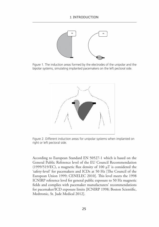
Unipolar bradycardia pacemaker systems have been found to be more susceptible to external EMFs than bipolar pacemakers [Toivonen et al. 1991; Wilke et al. 1998; Trigano et al. 2005B; Gwechenberger et al. 2006; Della Chiara et al. 2007]. In ICD devices the electrode leads are always bipolar. Interaction between the pacemaker and magnetic field can be caused by the loop, formed by the electrode parts of the lead, and the voltage induced between them. The area of the loop depends on the con-figuration of the lead. A bipolar lead has two electrodes near each other (1–2 cm) inside the heart, forming a small loop between them, whereas in a unipolar system, the area formed between the two poles is much larger. In addition, the induction area of the unipolar system depends on the size of the person. Being of a large size increases the induction area and thus adds the possibility of EMI. The induction areas formed by the unipolar and the bipolar electrode leads when the pacemaker is implanted to the left pectoral side of the body are presented in Figure 1. When the pacemaker is programmed to unipolar sensing settings, the site of the implantation is quite important. The induction area is much larger when a unipolar pacemaker is implanted to the left pectoral side instead of the right side. The induction areas of a unipolar pacemaker are presented in Figure 2. In addition, external magnetic fields can induce currents into the tissue around the pacemaker/ICD and hence lead to occurrence of EMI [Shah and Ellenbogen 2001; Irnich 2002; Irnich and Bernstein 2006; Della Chiara et al. 2007].
25
1 introduction
Figure 1. The induction areas formed by the electrodes of the unipolar and the bipolar systems, simulating implanted pacemakers on the left pectoral side.
Figure 2. Different induction areas for unipolar systems when implanted on right or left pectoral side.
According to European Standard EN 50527-1 which is based on the General Public Reference level of the EU Council Recommendation (1999/519/EC), a magnetic flux density of 100 µT is considered the ‘safety-level’ for pacemakers and ICDs at 50 Hz [The Council of the European Union 1999; CENELEC 2010]. This level meets the 1998 ICNIRP reference level for general public exposure to 50 Hz magnetic fields and complies with pacemaker manufacturers’ recommendations for pacemaker/ICD exposure limits [ICNIRP 1998; Boston Scientific, Medtronic, St. Jude Medical 2012].

26
1 introduction
EMI in pacemakers and ICDs can be mainly divided into malfunc-tions in either the sensing or pacing features. Other malfunctions, such as heating of the electrodes due to exposure to strong RF fields or complete electrical reset of the device, are rarer. Possible malfunctions to pacemaker/ICD function due to EMI are listed below [Shah and Ellenbogen 2001; Luechinger et al. 2002; Pinski and Trohman 2002A; Rasmussen et al. 2002; Hauser and Kallinen 2004; Kolb et al. 2004; Sweesy et al. 2004].
• Reversion to noise mode This is a common response of a pacemaker/ICD to external EMFs.
It results from algorithms in the microprocessor of the device, designed to protect its function. Reversion to noise mode usually leads to asynchronous pacing, depending on the settings of device manufacturer. Its purpose is to prevent inappropriate inhibition of pacemaker output from sensed noise. The noise mode can be pro-grammed individually beforehand and the pacemaker/ICD usually returns to its normal mode when the external field disappears.
• Pacing inhibition, e.g., complete or intermittent loss of pacing The pacemaker interprets an external signal as intrinsic heart activity
(oversensing) and stops the pacing, even in the absence of any int-rinsic rhythm. Long-term malfunctions of complete loss of pacing are rare because of the protecting algorithms of the pacemaker but short term malfunctions are common.
• Triggering of fast or premature pacing Atrial oversensing of a dual-chamber pacemaker or ICD can trigger
ventricular pacing at (or near) the upper tracking limit. Alternative-ly, automatic mode switching (AMS) can occur if it is enabled. The most common automatically swithed mode is ventricular pacing. Atrial or ventricular pacing during inappropriate AMS can lead to asynchronous atrial pacing in DDI mode and asynchronous ventricular pacing in VVI mode, respectively. It can also lead, though very rarely, to arrhythmias and pacemaker syndrome. In some pacemakers, triggering of the noise reversion mode is also possible. More rarely, EMI can induce rapid pacing via some other mechanisms.

27
1 introduction
• False arrhythmia detection in ICDs The ICD interprets external signal as ventricular tachycardia (VT)
or -fibrillation (VF) and treats it with ATP or by giving a high voltage therapy shock.
• Activation of the magnetic switch The magnetic switch (Reed switch) of a pacemaker or an ICD
usually closes when external static magnetic field reaches 1–3 mT and induces temporary asynchronous pacing. It blocks the interpretation and treatment of tachyarrhythmias in most ICDs. Normal operation usually returns after the magnetic field disap-pears. However, in some ICD models, after few tens of seconds, the magnetic switch stays closed until reprogramming of the device. Many new devices have an alarm sound to indicate that the switch is closed or the function is inhibited.
• Electric reset Strong external interference can induce a high voltage peak into
the pacemaker/ICD electrode lead system and cause a transition to reset mode. In reset mode, the pacemaker functions only with basic factory preset settings. The reset mode does not convert back when EMFs disappear and reprogramming of the device is needed to restore its normal function.
• Dangerous heating of the electrode tips Heating of the electrode tips can cause burns to the electrode-tissue
junction which can increase the pacing threshold and render the pacemaker unable to pace the heart. This is a very rare malfunction but it can happen due to strong RF-fields such as used in MRI.
• Damage to the electric components Permanent damage of the pacemaker/ICD due to strong EMI can
affect its function and even terminate it, leading to replacement of the device. However, this kind of damage is very rare.
• External signal is interpreted as a programming signal Very rarely an external signal can be interpreted as a programming
signal, leading to reprogramming of the device.

28
1 introduction
Another type of EMI with pacemakers and ICDs is telemetry interfer-ence. EMFs can be interpreted as monitoring or programming telemetry signals and thus effect the telemetry process. Telemetry interference can be clinically significant, especially because pacemaker/ICD treatment is moving toward remote monitoring and programming [Thaker et al. 2008].
29
2 lITERATuRE REvIEW
This literature review focuses on experimental studies and case reports presenting results that show electromagnetic interference with pacemakers/ICDs, ruling out temporary interference with device programming telem-etry and EMI from ionizing radiation. In addition, the articles considered here have been published mainly during the past 15 years. Older reports were discarded due to developed techniques of the pacemakers and ICDs.
In this literature review, the Pubmed database was used to track suit-able publications concerning pacemaker/ICD EMI. For some sources of EMI, such as MRI, great amounts of publications were found and only some of them could be included to this review due to its limited size.
2.1 In vitro laboratory studies using Helmholtz coil
This chapter reviews in vitro studies conducted in laboratory settings using a Helmholtz coil to generate magnetic fields and a body phantom to simulate real implantation of a pacemaker or an ICD. In vitro and in vivo studies on EMI from real-life electric devices and applications are reviewed in Chapter 2.3. In addition, this chapter describes different simulators of human body and tissues used in in vitro studies on EMI in pacemakers/ICDs.
The in vitro tests reviewed here are real experimental studies on pace-maker/ICD EMI using Helmholtz coil systems. Articles mainly present-ing new test protocols or their validation were excluded from the review. Also studies where EMI test signals were applied to the pacemaker/ICD input were excluded.

30
2 literature review
Only one of this kind of in vitro interference study using Helmholtz coils to produce magnetic fields in laboratory settings was found. Della Chiara et al. investigated one pacemaker with different programmed modes and settings using sinusoidal, 50 Hz magnetic fields up to 2 mT. In addition, the tests were repeated with three different pulsed fields us-ing the sinusoidal frequency of 50 Hz. With continuous waves, standard asynchorous pacing was observed with a minimum magnetic flux density of 42 µT when atrium (sensing and pacing) and ventricle (only pacing) were unipolar. When atrial sensing was bipolar and pacing unipolar with unipolar ventricle, irregular asynchronous pacing was observed with a minimum field of 950 µT. With pulsed waves and totally unipolar set-tings, atrial tracking, where a falsely sensed atrial signal drives ventricle pacing, was observed at a minimum field of 13 µT. Random inhibition of the pacemaker was observed at a minimum of 11 µT, and complete inhibition at a minimum of 38 µT. With pulsed waves and bipolar atrium and unipolar ventricle, complete pacemaker inhibition and random or standard asynchronous pacing was observed with a minimum magnetic flux density of 35 µT [Della Chiara et al. 2007].
Several phantoms or body simulators, in which a pacemaker/ICD has been immersed in saline or gelatin during EMI tests, have been de-scribed in the literature. One of them has been used in in vitro tests using Helmholtz coils, mentioned above. Some of the simulators described here have been presented in studies that are not reviewed in this literature review. For example, an electrically inactive, real size, whole body model was presented by Gustrau et al. [Gustrau et al.2002]. A similar whole body mannequin was used by Korpinen et al. [Korpinen et al. 2012]. An electrically passive, real size, torso phantom was used by Gwechen-berger et al. [Gwechenberger et al. 2006]. Different size human trunk simulators, for example, cylindrical and cubical tanks with or without heartbeat simulators have also been used [Bassen et al. 1998; Miller et al. 1998; Wilke et al 1998; Barbaro et al. 1999; Tri et al. 2004; Kainz et al. 2005; Irnich and Bernstein 2006; Brand et al. 2007; Dubner et al. 2007; Bassen 2008; Seidman et al. 2010; Gomez et al. 2013; Weyer et al. 2012]. More complex phantoms with chambers simulating atriums and ventricles of the heart, as well as physiological, electrical and anatomical features of the heart using heartbeat simulators, have been introduced [Angeloni et al. 2003; Fukuta et al. 2005; Della Chiara et al. 2007]. In

31
2 literature review
addition, some in vitro tests were conducted in air, without a phantom [Garofalo et al. 2002; Kainz et al. 2005; Jilek et al. 2010].
2.2 In vivo laboratory studies using Helmholtz coil
In vivo EMI studies conducted in laboratory settings using Helmholtz coil to produce magnetic fields are reviewed in this chapter. Only two studies could be found.
Trigano et al. performed 250 tests to 245 pacemaker patients using 50 Hz magnetic fields with a maximum flux density of 100 µT. EMI was observed in four of the 250 tests. A mode switch occurred with three of the pacemakers tested as unipolar settings leading to transient asynchronous pacing in two pacemakers and to pacing inhibition result-ing in complete atrioventricular block in one of the pacemakers. With the fourth interfered pacemaker (bipolar) transient ventricular pacing with a shorter than programmed atrioventricular delay was observed [Trigano et al. 2005B].
The other in vivo study utilizing Helmholtz coil was published by Frank et al. Sixty pacemaker patients were exposed to 50 µT magnetic fields with frequencies of 50 Hz and 60 Hz. All of the pacemakers were reprogrammed to unipolar settings and highest sensitivities that did not induce muscular inhibition while moving. Transient reversion to noise mode was observed in six, transient acceleration due to atrial detection of interference in three, and T wave detection by the ventricular lead in one of the pacemakers tested [Frank et al. 2003].
2.3 studies with real sources of EMFs
2.3.1 non-medical environment
In this chapter, studies on real-life sources of EMFs that have been found to cause EMI with pacemakers and ICDs are reviewed.

32
2 literature review
Electronic article surveillance (EAs) systems
Electronic article surveillance (EAS) systems are used for example in stores, museums, and libraries to prevent thefts. They are commonly walkthrough gates that are installed in the vicinity of cash desks or exits of the stores. The gates usually involve coils that generate a magnetic field and a field receiving component that detects magnetic tags brought to the field. EAS systems can be in four frequency ranges: 1) non-linear magnetic (10 Hz–20 kHz, continuous wave at specific frequency), 2) resonant inductive or acoustomagnetic (20–235 kHz, pulses at specific frequency), 3) resonant radio frequency (1–20 MHz, sweeps through a frequency band), and 4) non-linear microwave (0.8–2.5 GHz, pulsating waves) [ICNIRP and WHO 1999; Bolte and Pruppers 2006].
Mugica et al. investigated 204 pacemaker patients with an acousto-magnetic and a magnetic audio frequency EAS system, emitting inter-mittent 58 kHz and continuous 73 Hz signals. EMI occurred with 17% of the pacemakers, with both unipolar and bipolar lead configurations, appearing in false under- and oversensing, and mode disruptions. Over twice as many malfunctions occurred with the acoustomagnetic system as with the magnetic audio frequency system [Mugica et al. 2000]. Similarly, in a study by McIvor et al, 50 pacemaker patients were tested with two magnetic audio frequency, three swept radiofrequency, and one acoustomagnetic EAS systems. One magnetic audio frequency system interfered with 4%, the swept radiofrequency systems with 0%, and the acoustomagnetic system with 96% of the unipolar and bipolar pace-makers tested. Detected malfunctions were asynchronous pacing, atrial and ventricular oversensing leading to ventricular tachycardia detection and pacing inhibition and EMI induced pacing [McIvor et al. 1998]. However, Wilke et al. tested 53 pacemakers (unipolar and bipolar) in vivo and nine pacemakers (all unipolar) in vitro with antitheft device transmitting pulsed 120 kHz magnetic fields. They found no EMI with the pacemakers tested in vivo but pacemaker inhibition with all the pacemakers tested in vitro [Wilke et al. 1998]. In addition, Groh et al. investigated EAS systems and ICDs by testing 169 ICD patients with one pulsed acoustomagnetic system and two different electromagnetic systems. Three of the 169 ICDs tested with acoustomagnetic systems showed inappropriate tachyarrhythmia detection likely to result in ICD

33
2 literature review
therapy shocks. Some 126 of the ICDs were also tested with pacing fea-ture on and 19 experienced EMI. Seven of them experienced a clinically relevant malfunction: oversensing leading to intermittent or complete loss of pacing. These malfunctions occurred with five of the ICDs when they were tested with the acoustomagnetic system and with two of the ICDs while tested with one of the electromagnetic systems [Groh et al. 1999].
Induction hobs
Induction hobs are commonly used in modern households and industrial kitchens. The operation of an induction hob is based on the magnetic field induced energy to a metallic pan on the plate. An induction coil under the ceramic surface of the hob generates magnetic field, which induces eddy currents to the pan leading to generate heat. The operation frequencies of the induction hobs are in the range of 20–50 kHz, with powers of some kilowatts [ICNIRP and WHO 1999].
Frank et al. tested 60 patients with a unipolar, dual chamber pace-maker using an induction hob operating with frequencies from 20 kHz to 50 kHz. They found EMI with one pacemaker which shifted out of its special programme during the tests, but maintained its standard programme [Frank et al. 2003]. Hirose et al. used four different kinds of unipolar pacemakers to perform in vitro inhibition and asynchronous pacing tests near an induction oven operating with frequencies of 25 kHz and 34 kHz. 32 cm was found to be the maximum distance above the induction hob up to which pacemaker inhibition occurred. The maximum distance above the hob up to which asynchronization occurred was found to be 34 cm [Hirose et al. 2005].
Welding equipment
Welding is a technique to join metal pieces together by heating the metal and bringing the components together. In addition to gas and laser welding, several types of electric welding processes are used in different industry sections: arc welding (for example MIG), resistance welding, high frequency resistance welding, and electron beam welding. Arc weld-ing involves striking an electric arc between an electrode and a workpiece to melt the materials to be joined using direct, pulsating direct, and

34
2 literature review
alternating current. The AC frequency is usually the mains frequency of 50 Hz but higher frequencies can also be used. The electric current used in arc welding varies from 50 A to 1 kA depending on the process and the metal. Resistance welding uses short periods of current across the gap between the two components pressed firmly together. High frequency resistance welding does not use mains frequency but frequencies above 100 kHz. In addition, the electron beam welding process uses EMFs to heat the metal with an electron gun in vacuum and is, thus, mechanized [Hietanen et al. 2002; Bolte and Pruppers 2006].
No scientific studies on pacemaker/ICD EMI during electric weld-ing could be found from the literature published over the past 15 years. However, electric and especially arc welding can be considered a potential source of clinically significant EMI with pacemaker and ICD function.
Mobile phones and base stations
Wireless telecommunication contains signal transmission between mo-bile telephones and fixed base stations. Old, analogue mobile phones (for example, Nordic Mobile Telephone (NMT)) transmit continuous frequency-modulated sinusoidal carrier signal having the same maxi-mum and average powers. Studies about analogue mobile phones are left out of this literature survey due to their outdated results. At present, the most commonly used mobile phones are digital systems based on the harmonized Global System for Mobile Communications (GSM) transmitting pulsed signals consisting of short carrier wave bursts. GSM phones operate at frequencies of 900 and 1 800 MHz with the maximum peak power of its output signal 2 W (for 900 MHz) and 1 W (for 1 800 MHz) and the maximum time-average power of 1/8 of the peak power. Other common digital systems include the Terrestrial Trunked Radio (TETRA) used by the police and other emergency personnel. TETRA operates at around 400 MHz and its maximum peak power output is 30 W. The Universal Mobile Telecommunication System (UMTS), the third generation mobile communication system, operates at frequencies of 1 900–2 200 MHz [Hietanen et al 2002].
Mobile phones have been a fairly common source of EMI with older pacemaker models [Altamura et al. 1997; Hayes et al. 1997; Bassen et al. 1998; Barbaro et al. 1999]. Altamura et al. found pacemaker interfer-

35
2 literature review
ence in 21.5% of 200 in vivo tested, mostly unipolar pacemakers, when exposed to GSM mobile phones. Some 18% of the pacemakers tested experienced inhibition, 5.4% of the 72 pacemakers in which it was pos-sible to perform mode switch test switched into asynchronous pacing mode, 9.4% of the 74 pacemakers with DDD/VDD mode experienced synchronization by EMI [Altamura et al. 1997]. Hayes et al. studied GSM EMI with 980 pacemaker patients and reported the incidence of interference to be 23.7%. Both unipolar and bipolar pacemakers were reported to experience tracking interference sensed on the atrial channel, noise reversion or asynchronous pacing, and ventricular inhibition as the most common types of EMI. In addition, atrial inhibition, ventricular safety pacing, undersensing, and rate-adaptive sensor-driven pacing were also seen, although, less commonly [Hayes et al. 1997]. EMI between digital mobile phones and ICDs was tested in vitro by Bassen et al. Three ICDs were tested with two phones and all of them experienced pacing inhibition with one or two of the phones leading in three out of four cases to inappropriate ICD shock [Bassen et al. 1998]. In ad-dition, Barbaro et al. tested ICDs with GSM phones both in vitro and in vivo. Four out of six ICDs tested in vitro in air experienced pacing inhibition, electrical reset, and false VT and VF detection. No EMI was observed during the in vitro tests in saline. During the in vivo tests, three out of 13 pacemakers tested, all of the same model and in DDD mode showed ventricular triggering with the interfering signal at the upper rate [Barbaro et al. 1999].
Newer pacemaker and ICD models are more resistant to RF EMFs and thus interference from digital mobile phones does not pose a great risk today [Chiladakis et al. 2001; Elshershari et al. 2002; Tandogan et al. 2005A; Ismail et al. 2010]. Some reports about the mobile phone EMI particularly with unipolar pacemakers, but also with bipolar de-vices, can, however, be found after the year 2000 [Hekmat et al. 2004; Tandogan et al. 2005B; Trigano et al. 2005A]. Hekmat et al. found two out of 100 pacemakers tested in vivo to experience pacing inhibition with a GSM mobile phone. The same effects were seen with both unipolar and bipolar lead configuration [Hekmat et al. 2004]. Tandogan et al. tested 679 pacemaker patients using both unipolar and bipolar lead po-larity with every pacemaker tested. Of the pacemakers tested 5.5% were adversely affected showing malfunctions of conversion to asynchronous

36
2 literature review
mode, inhibition, and ventricular triggering. When the lead polarity was unipolar, the rate of malfunctions was higher and the effects more significant when compared to the bipolar configuration [Tandogan et al. 2005B]. Trigano et al. found oversensing leading to irregular and rapid ventricular pacing or to transient, inappropriate safety pacing in four out of 330 tests performed on 158 pacemaker patients with digital mobile phones and pacing inhibition leading to presyncope in one of the tests. All but one of the malfunctioned pacemakers had a bipolar lead configuration [Trigano et al. 2005A].
Most of the adverse effects found in pacemaker/ICD function caused by exposure to the RF EMFs of digital cellular phones have occurred while the phone has been positioned directly above the pacemaker/ICD or at a short distance from it.
The operation of mobile phones is based on the radio signal transfer between the phone and antennas of a base station. Mobile phones are connected to the nearest base station by two separate radio links: the uplink from the phone to the base station transmitting speech of the caller, and the downlink from the base station to the phone transmitting speech of the respondent. The coverage cell of a base station is ideally hexagonal and ranges from 1 to 35 km, but can vary in size. It contains several transmitters, whose outputs are combined and fed to the anten-nas. The typical output power of a single transmitter is between 10 and 40 W. The base station antennas are normally located in towers and on the roofs and ceilings of buildings [Hietanen et al. 2002].
Mobile phone base stations have not been reported to cause EMI with pacemakers or ICDs. However, because the EMFs emitted by base stations are similar to those emitted by mobile phones, it is possible that they can also interfere with pacemaker function [Alanko et al. 2008, Toivonen et al. 2009]. This may happen in some specific situations when a pacemaker is in the close vicinity of a base station antenna, for instance when a maintenance worker with a pacemaker installs or maintains the antenna with his/her chest close to an active transmitter.
Electric trains
In most of the European countries, 50 Hz is the operating frequency used by electric trains with AC overhead voltage supply between 10 and 30

37
2 literature review
kV. The magnetic fields inside the cabins vary greatly due to variations in the speed and the load carried by the train [Hietanen et al. 2002]. No published reports were found about possible EMI with pacemakers in electric trains. However, one study has been published about the risk of EMI with implanted arrhythmia devices in magnetically levitated linear motor car train. No interference either with pacemakers or with ICDs was observed in the study [Fukuta et al. 2005].
High voltage transmission lines
High voltage transmission lines produce quite high electric and mag-netic fields in the surrounding area and below the lines. Under 400 kV power lines, the magnetic flux density is 10–15 µT and the electric field strength 6–10 kV/m. The corresponding values under 765 kV lines are 30–40 µT and 10–12 kV/m. EMFs generally decrease to background strengths at distances of 50 to 100 m, depending on the line design and current [Hietanen et al. 2002].
EMFs emitted by overhead power lines have been reported to cause EMI with pacemakers. Korpinen et al. tested in vitro 31 unipolar pace-makers under 400 kV power lines. In addition, 11 of the pacemakers were also tested with bipolar lead configuration. During the tests, one pacemaker experienced atrial high rate episode when programmed with unipolar settings. Minor disturbances were also seen in a few other pace-makers tested [Korpinen et al. 2012].
Permanent magnets
Devices that contain permanent magnets emit static magnetic fields (0 Hz). Static magnetic fields produced by, for example, headphones, and small neodymium magnets have been shown to cause EMI with pacemak-ers and ICDs [Wolber et al. 2007; Ryf et al. 2008; Lee et al. 2009]. EMI can occur when the magnetic switch of a pacemaker or an ICD is affected by a static magnetic field. In pacemakers and ICDs, Reed switches are typically closed by 1.0–3.0 mT magnetic fields and reopen at 0.7–1.0 mT, depending on the device model [Luechinger et al. 2002; Kolb et al. 2004]. In recent years, Hall sensors and semiconductor magnetic switches are more and more used. In them, opening and closure of the switch oc-

38
2 literature review
cur at the same field strengths. The closure of a magnet switch results in temporary asynchronous pacing in pacemakers. In most ICDs it results in temporary suspension of tachyarrhythmia detection, leaving bradycardia pacing function unaffected [Wolber et al. 2007]. However, although usually the ICD conversion to magnet mode due to static magnetic field is only a temporary effect, the effects can be permanent in some makes of ICDs. With certain programming in some ICD models, arrhythmia detection and therapy can be permanently deactivated in 30 seconds by a magnet [Rasmussen et al. 2002; Hauser and Kallinen 2004].
Wolber et al. tested 41 pacemaker patients and 29 ICD patients with two spherical magnets: a necklace made of 45 spherical magnets, and a magnetic name tag all made from neodymium-iron-boron. EMI was ob-served in all the pacemakers and ICDs tested. The maximum distance at which EMI occurred was 3 cm [Wolber et al. 2007]. Ryf et al. investigated one sample pacemaker in vitro with different kinds of magnets made from the same compounds with nickel coating, one levitation toy magnet, and one conventional ferrite office magnet. Pacemaker function was found to suffer interference at distances from 1 cm to 24 cm depending on the magnet tested [Ryf et al. 2008]. Portable headphones were found to induce clinically significant EMI in pacemakers and ICDs in a study by Lee et al. Some 45 patients with a pacemaker and 55 with an ICD were tested with eight different portable headphones resulting in clinically significant EMI observed in 9/45 of the pacemakers and 21/55 of the ICDs. The most common effect was magnet response characterized in all nine pacemakers by asynchronous pacing and in ICDs by audible sounding of the magnet alarm and inhibition of tachyarrhythmia detection [Lee et al. 2009].
other non-medical sources of EMI: digital media players, Metal detectors, and Radiofrequency identification (RFId) systems
Several other kinds of electric devices have also been studied and found to cause EMI with pacemakers and ICDs. Digital media players are a format for portable music and are commonly carried in a shirt pocket. Thaker et al. tested four types of media players with 100 pacemaker patients and found that 19% of the pacemakers tested experienced inter-ference during the tests, regardless of their lead configuration (unipolar vs. bipolar) [Thaker et al. 2008].
39
2 literature review
Handheld and walk-through metal detectors are used in security applications at, for example, airports and official buildings. Metal detec-tors sense disturbances in magnetic field when a metallic object enters its detection zone. The transmitted field creates an eddy-current in the metallic object that generates an opposing field [Bolte and Pruppers 2006]. Walk-trough detectors operate with continuous sinusoidal sig-nals at one or more frequencies (630 Hz–7.375 kHz) or with pulsating signals at low-frequencies (89–909 Hz) and handheld detectors usually with unmodulated sinusoidal signals of 13 kHz–1.9 MHz [ICNIRP 2004]. Kainz et al. tested in vitro a security system simulator with four unipolar pacemakers and compared the results with tests using two actual walk through metal detectors. Both, the simulator and the actual detectors were observed to cause EMI with the pacemakers resulting in partial atrial and intermittent ventricular inhibition, as well as full atrial inhibition and ventricular pulse tracking [Kainz et al. 2005].
Radiofrequency identification (RFID) systems are used to locate, identify, and track objects. They consist of transponder tags and an inter-rogator reader. Tags can be inserted in or attached to products like cards, badges, or labels and readers read and write information to them. Readers range from large portal antennas, to desktop pad workstations, and to small handheld portable readers. RFID systems operate at many different frequencies: low-frequency RFID (125–135 kHz), high-frequency RFID (13.56 MHz), active 433 MHz RFID, ultra high-frequency (915 MHz) RFID, and microwave (2.45 GHz) RFID [ICNIRP 2004; Seidman et al. 2010]. Seidman et al. reported significant malfunctions in both pacemakers and ICDs when exposed to EMFs emitted by passive RFID systems. Some 67% of the 15 pacemakers tested in vitro experienced interference at a maximum distance of 60 cm from low frequency (134 kHz) RFID and 6% of them at a maximum distance of 22.5 cm from high frequency (13.56 MHz) RFID. Respectively, 47% of the 15 ICDs tested in vitro experienced EMI at a maximum distance of 40 cm from low frequency RFID and 1% at a maximum distance of 7.5 cm from high frequency RFID [Seidman et al. 2010].

40
2 literature review
2.3.2 Medical environment
Medical environments are among the most likely places for EMI to occur with pacemakers and ICDs. However, patients with a pacemaker or ICD may also require treatment and diagnostics with devices that introduce strong electric currents inside the body or emit high-intensity electromagnetic fields. Some of the most common sources of EMI in medical settings are presented in this chapter.
Magnetic Resonance Imaging
Magnetic resonance imaging (MRI) is a widely used technology for di-agnostics as it provides great advantages in soft-tissue imaging compared to other available imaging systems. It poses, however, hazards to patients with a pacemaker or an ICD [Pinski and Trohman 2002B; Nair and Roguin 2005; Götte et al. 2010]. MRI uses static magnetic fields that cause attractive forces on ferromagnetic components, radiofrequency fields (10–100 MHz) that can cause heat damage, and gradient magnetic fields that can induce electrical currents in the pacemaker/ICD [Hietanen et al. 2002; Roguin et al. 2008]. In addition, combination of these fields can alter the function of pacemakers/ICDs and cause electrical reset or damage to the device or to its leads [Roguin et al. 2008].
Several studies have reported problems in pacemaker/ICD function during MRI scans and not all of them could be reviewed here. For exam-ple, Heatlie and Pennell presented five patients with a bipolar pacemaker undergoing six cardiovascular MRI scans using a 0.5 T scanner. In one case, the pacemaker began pacing at maximum tracking rate [Heatlie and Pennell 2007]. In a study of Naehle et al., 18 patients with an ICD un-derwent an MRI examination with a 1.5 T scanner. In two of the ICDs, oversensing of RF noise as VF was detected. A statistically significant decrease in battery voltage after the scans was observed in 16 of the ICDs tested (no data was available for two ICDs). Later follow up showed a full recovery of battery voltage after 4 of 16 MRI examinations [Naehle et al. 2009]. Gimbel et al. studied seven ICD patients undergoing eight MRI scans at 1.5 T. One of the ICDs tested experienced a power reset during a lumbar spine scan [Gimbel et al. 2005].

41
2 literature review
The U.S. Food and Drug Administration (FDA) database reports several deaths associated with MRI scans of patients with a pacemaker in the 1980s and 90s [CDRH Working group 1997]. In addition, Martin and Sandler reported at least 17 supposed MRI associated deaths world-wide among patients with pacemakers by 2007 [Martin and Sandler 2007]. However, ‘MRI-safe’ pacemakers and ICDs are being developed and tested [Sutton et al. 2008; Forleo 2010; Jung et al. 2011; Wilkoff et al. 2011]. With appropriate precautions and careful monitoring, MRI can be considered to be relatively safe to patients who are not pacemaker dependent [Gimbel et al. 2005; Gimbel 2008; Roguin 2008; Naehle et al. 2009; Naehle et al. 2011; Zikria et al. 2011].
Electrocautery
Electrocautery is an electrosurgical technique that promotes hemostasis by heating a metal instrument without any current passed in the body [Pinski and Trohman 2002B]. The term ‘electrocautery’ can also be used when referring to electrosurgery. With this definition it uses a knife to cut and coagulate tissue with radiofrequency current. The generated RF currents can be interpreted by a pacemaker or ICD as an intracardiac signal. Electrocautery can also deliver a large amount of energy to the body, which can damage the pacemaker circuitry or myocardium at the pacemaker electrode-tissue interface [Shah and Ellenbogen 2001; Yerra and Reddy 2007; Dyrda and Khairy 2008]. At least one study after the year 2000 has reported minor EMI with pacemakers and ICDs during electrocautery [Cheng et al. 2008]. Cheng et al. studied 57 ICD and 35 pacemaker patients who underwent non-cardiac surgical or endoscopic electrocautery. As a result, minor changes in lead parameters were noted, in addition to, three cases (two pacemakers, one ICD) of atrial mode switch episodes, and two cases (both pacemakers) of inappropriate sens-ing of ventricular noise [Cheng et al. 2008].
Electrical nerve and Muscle stimulation
Transcutaneous electrical nerve stimulation (TENS) is used to treat acute and chronic musculoskeletal pain. It is a noninvasive technique that consists of electrodes placed on the skin trough which rectangular

42
2 literature review
electric pulses are conducted to the body with a low frequency of 20–110 Hz [Pinski and Trohman 2002B].
Studies on TENS treatment have reported cases of inhibition of pacemaker function as well as sensing of inappropriate arrhythmias by ICDs [Holmgren et al. 2008; Carlson et al. 2009]. In a study by Carlson et al, 27 patients with a unipolar or bipolar pacemaker were tested us-ing TENS. Of the pacemakers tested 81% experienced EMI resulting in inhibition of one or more pacemaker signal [Carlson et al. 2009]. Holmgren et al. tested 30 ICD patients with TENS treatment. Some 27% of the ICDs experienced false VT/VF interpretations, 47% had premature ventricular extra beats, and 16% experienced others kinds of interactions: interpretations as noise, undersensing, and loss of telemetry connection [Holmgren et al. 2008].
Cronin et al. studied 2 and 50 Hz repetitive nerve stimulation (RNS) in 10 patients with an ICD and four with a pacemaker. In two subjects with an ICD, EMI was observed as noise. Two of the four pacemakers were tested only with bipolar sensing configurations and two with bipolar and unipolar configurations. Three of the pacemakers were observed to experience EMI. Only one pacemaker with bipolar sensing experienced a slight increase in paced ventricular rate due to atrial oversensing. How-ever, both of the unipolarly programmed pacemakers detected transient inhibition of ventricular pacing [Cronin et al. 2013].
Neuromuscular electric stimulation (NMES) is used to prevent atro-phy of immobilized muscles, for example to maintain leg muscle strength in patients with severe heart failure. These patients with heart failure, however, often also have a cardiac ICD. Crevenna et al. subjected eight patients with an ICD to NMES of the neck and shoulder and to the thighs. Inappropriate ventricular sensing was observed in two of the ICDs tested during stimulation of the neck and in two during thigh stimula-tion, and false atrial sensing was seen in two of the four dual chamber ICDs tested during stimulation of the neck [Crevenna et al. 2003].
Wireless capsule Endoscopy
Wireless video capsule endoscopy is a noninvasive diagnostic technique, which enables visualization of the mucosa of the intestine without ra-diation or traditional endoscopy [Yerra and Reddy 2007]. The system

43
2 literature review
consists of a capsule that contains a camera, lights, antenna, power source, and a telemetry transmitter. The swallowed capsule transmits data at radio frequency to an external recorder [Dubner et al. 2007]. This signal can, according to some studies, potentially interfere with pacemaker/ICD function [Dubner et al. 2005; Dubner et al. 2007]. Dubner et al. observed reversion to noise mode forcing asynchronous behavior with four of the pacemakers of 100 patients tested during wireless endoscopy. All of the four pacemakers experiencing interference were programmed as bipolar sensing settings [Dubner et al. 2005]. The same group also tested ICDs, both in vitro and in vivo, during wireless endoscopy. One of six ICDs tested in vitro experienced oversensing and delivery of an inappropriate therapy, whereas all six ICDs tested in vivo showed no traces of EMI [Dubner et al. 2007].
left ventricular Assist devices
Left ventricular assist devices (LVADs) are cardiac assist devices that are used to treat heart failure as destination therapy or bridge to heart trans-plantation. LVADs are mechanical pumps that take over the function of the damaged ventricle and restore normal hemodynamics and end-organ blood flow [Goldstein et al. 1998]. Simultaneous use of LVADs and pacemakers/ICDs has triggered EMI between the devices [Foo et al. 2009; Oswald et al. 2009; Ambardekar et al. 2010].
Oswald et al. reviewed 46 ICDs implanted in LVAD recipients. Four of the 46 ICDs had to be replaced immediately after implantation of the LVAD due to complete and irreversible loss of telemetry between an ICD and a programming device [Oswald et al. 2009]. In a review of 15 patients with a pacemaker or an ICD who subsequently had implanta-tion of a LVAD by Foo et al., changes in lead parameters were observed after LVAD implantation: trend of decreased sensing of the intracardiac electrogram from the right ventricular (RV) lead, increase in RV lead stimulation thresholds, and changes in RV lead impedance. Three of the 15 patients had a significant increase in ventricular tachyarrhythmia episodes post-LVAD as compared to pre-LVAD. One ICD experienced ventricular oversensing leading to inappropriate defibrillation therapy [Foo et al. 2009]. Complying with these results, Ambardekar et al. studied 31 ICD patients implanted with a LVAD and found significant post-

44
2 literature review
LVAD changes in RV lead parameters: decrease in sensing amplitude and impedance, and increase in capture threshold [Ambardekar et al. 2010].
Radiofrequency catheter Ablation
Radiofrequency catheter ablation is used for treatment of supraventricular and ventricular arrhythmias. It produces 400–500 kHz signals between RF catheter tip and a large indifferent electrode usually placed on the patient’s thigh [Misiri et al. 2012].
In a study by Lakkireddy et al., of 86 patients that underwent RF ablation of atrial fibrillation, pacemaker atrial-lead dislodgement was noted in two patients [Lakkireddy et al. 2005]. Burke et al. investigated 107 patients with pacemakers and defibrillator ventricular lead systems undergoing RF atrio-ventricular junction ablation and compared the effects of RF current on ventricular lead systems. Both the pacemaker and defibrillator leads (previously implanted or temporary) showed an increase in ventricular pacing voltage thresholds, many of them requiring device reprogramming or lead revision [Burke et al. 2001]. However, Sadoul et al. observed pacemaker inhibition, reset to backup mode, noise mode behavior, tachycardia detection, erratic behavior, oversensing, loss of ventricular capture, or increase in ventricular threshold in 53% of the 38 (mainly unipolar) pacemakers tested during RF catheter ablation. Three devices resetting to backup mode required reprogramming to obtain normal operation [Sadoul et al. 1997].
Electric dental equipment
Electronic dental equipment items are sources of low-intensity EMFs and have been studied as possible sources of pacemaker/ICD EMI. Fourteen electric dental devices were tested in vitro for possible interfer-ence with two pacemakers, one unipolar and one bipolar, by Miller et al. Atrial and ventricular pacing were inhibited in both pacemakers by EMI caused by an electrosurgical unit, an ultrasound bath cleaner, and two magnetorestrictive ultrasonic scalers [Miller et al. 1998]. Brand et al. tested in vitro ten different electrical dental devices with three ICDs. An ultrasound bath cleaner was found to cause false detection of ventricu-lar noise in two of the ICDs tested [Brand et al. 2007]. Garofalo et al.

45
2 literature review
tested in vitro effects of five apex locators on the function of a unipolar pacemaker. One of the apex locators tested was observed to cause pac-ing inhibition in the pacemaker [Garofalo et al. 2002]. Six electronic apex locators were tested, also in vitro, with one unipolar pacemaker by Gomez et al. One apex locator was found to cause EMI with the pace-maker detected as false heart activity [Gomez et al. 2013]. Roedig et al. tested nine electronic dental devices in vitro with two pacemakers and two ICDs. EMI occurred with three of the devices: pacing inhibition was observed in both pacemakers and in one of the ICDs during operation of the battery-operated composite curing light, the use of the ultrasonic scaler interfered with the pacing of one of the pacemakers and both of the ICDs, and the operation of the ultrasonic cleaning system interfered with both of the pacemakers [Roedig et al. 2010].
other medical sources of EMI: lithotripsy, Magnetic drapes, Magnetic navigation systems, and Hyfrecators
Some other medical applications have also been observed to cause EMI with pacemakers/ICDs. Extracorporeal shock wave lithotripsy is used to noninvasively disintegrate urinary tract calculi and gall bladder stones [Dyrda and Khairy 2008]. During the treatment, the patient lies in a water bath and multiple hydraulic shocks are generated underwater and focused on the calculi by an ellipsoid metal reflector. Pacemakers and ICDs can be subject to EMI from the spark gap and mechanical damage from the hydraulic shock wave [Pinski and Trohman 2002B]. Electric reset of one ICD, out of four tested during shock wave lithotripsy treat-ment was reported by Chung et al. [Chung et al. 1999].
Sterile magnetic drapes are used during surgery to hold metal instru-ments on the sterile field. Zaphiratos et al. tested 50 pacemaker patients with a magnetic drape containing 70 removable magnets placed over the pacemakers. Asynchronous pacing due to activation of the magnetic switch the pacemakers was observed with 94% of the pacemakers, and in 54% of these pacemakers, EMI ceased when the drape was pulled 3 cm caudally and at 15 cm, no pacemaker experienced EMI [Zaphiratos et al. 2013].
A magnetic catheter navigation system, which is used for remote mapping and ablation, works with 80 mT static magnetic field and ap-plies time-dependent field gradients. It allows remote directing of cath-

46
2 literature review
eters and guide wires in the cardiovascular system. Jilek et al. tested 77 pacemakers and 44 ICDs in vitro with one magnetic navigation system at its minimal magnet to magnet distance using a maximum of 0.1 T magnetic field. EMI was observed in six pacemakers tested resulting in reprogramming to a power-on-reset mode in five and abnormal variance of battery status in one pacemaker [Jilek et al. 2010].
Hyfrecators are commonly used in office based dermatologic surgery for hemostasis or destruction. A hyfrecator emits low-power high-frequency current pulses to the patient through a hand held electrode [Weyer et al. 2012]. Weyer et al. tested three pacemakers and three ICDs in vitro by exposing them to EMFs of two common hyfrecator units. None of the ICDs tested were affected by the hyfrecators. However, atrial inhibition and full inhibition of pacing was observed in the pacemakers in very close proximity to the hyfrecators [Weyer et al. 2012].
2.4 case Reports
Numerous cases of EMI with pacemakers and ICDs have been reported. Reports include cases of device malfunction from incorrectly grounded electric devices and systems, radiated EMFs, and medical applications. Some other devices, such as Taser stun gun and arc welding equipment, have been reported to cause EMI in real life situations [Haegeli et al. 2006; Trigano et al. 2006; Cao et al. 2007]. Energy delivery by a Taser stun gun was interpreted as VF by an ICD resulting in charging for VF therapy. The charged current, however, was diverted after the Taser energy delivery was finished [Haegeli et al. 2006]. Respectively, Cao et al. presented a report about high ventricular rate episodes stored in a bipolar pacemaker during an energy delivery by a Taser stun gun [Cao et al. 20074]. Trigano et al. reported a case of EMI with bipolar pacemaker by arc welding, stored as inappropriate atrial tachycardia leading to brief asynchronous ventricular pacing [Trigano et al. 2006].
Most of the published case reports describe situations where conduct-ing an electric current through the body of a pacemaker/ICD wearer has triggered EMI. There are, however, a few reported cases of EMI resulting from radiated EMFs. For example, electric article surveillance (EAS) systems used in stores have caused inappropriate ventricular

47
2 literature review
tachyarrhythmia detection and therapy shocks with ICDs [Mathew et al 1997; Santucci et al. 1998; Gimbel and Cox 2007; Koneru et al. 2011]. Gimbel and Cox also reported about loss of pacing in a single chamber pacemaker, and McIvor and Sridhar about rapid ventricular pacing due to atrial oversensing in a dual chamber pacemaker due to exposure to EMFs emitted by EAS systems [McIvor and Sridhar 1998; Gimbel and Cox 2007]. In addition, an induction heating rice cooker has been re-ported to cause EMI with a bipolar pacemaker [Nagatomo et al. 2009]. Additionally, a reproducible oversensing case of a pacemaker with an iPod placed approximately 5 cm above it was reported by Patel et al. The pacemaker registered high atrial and ventricular rates regardless of the atrial and ventricular sensitivity and pacing mode polarity (unipolar vs. bipolar) [Patel et al. 2007]. In addition, unintentional ICD magnet mode switches due to magnets in a decorative brooch and inside jacket pockets have been reported [Li 2007; Beirnart et al. 2011].
Inappropriate ICD shocks due to current leaks from malfunctioning or insufficiently grounded electrical systems have been reported to occur in swimming pools and while taking a shower [Manolis et al. 2000; Garg et al. 2002; Lee et al. 2002; Fernengel et al. 2007; Pai et al. 2008; Spurrell et al. 2008]. Conducted currents due to wet hands or hands in the water have been reported to trigger ICD shocks also with a power drill, washing machine, and submersible fish pond pump [Vlay 2002; Chan and Ho 2005]. Even a rare case of a lightning induced ICD shock while taking a shower has occured [Anderson et al. 2012]. Some cases have been reported about ICD shocks when touching a washing machine with dry hands [Sabaté et al. 2001; Kolb et al. 2002; Chongtham et al. 2007]. Other re-ported cases about non-medical sources of current leaks that have caused EMI with ICDs are, for example, a household lamp, refrigerator, kitchen stove, sewing machine, radio alarm clock, hydro-massage bath, percussion drill, electric pruner, and electrically powered watering system [Kolb et al. 2001; Al Khadra et al. 2006; Occhetta et al. 2006].
Several cases of EMI between medical applications and pacemak-ers/ICDs have been reported. These reports are mainly focused on pacemaker/ICD malfunction due to conducted currents from surgical electrocautery as well as from electronic nerve and muscle stimulation. Electrocautery has been reported to induce inappropriate pacemaker rate responses resulting in rapid ventricular pacing or an abrupt onset
48
2 literature review
of bradycardia followed by brief asystole [Wong and Middleton 2001; Wilson et al. 2006; Abdelmalak et al. 2011]. Two reports introduce cases of complete pacemaker failure during electrocautery leading in one case to immediate asystole and in both cases to pacemaker replacement [Ner-cessian et al. 1998; Peters and Gold 1998]. EMI during electrocautery has also caused false sensing of ventricular tachyarrhythmia by an ICD. However, therapy was averted because the interference noise stopped before the charging period of the ICD was finished. [Casavant et al. 1998]. Transcutaneous electrical nerve stimulation has been reported to lead to inappropriate ICD shocks, and peripheral nerve stimulation has resulted in complete inhibition of a unipolar pacemaker [Philbin et al. 1998; Vlay 1998; Pyatt et al. 2003; Siu et al. 2005; Occhetta et al. 2006; Engelhardt et al. 2007]. Inappropriate ICD shocks have also been received during electronic muscle stimulation treatments [Glotzer et al. 1998; Kolb et al. 2001].
A magnetic catheter navigation system has been reported to induce EMI with a bipolar pacemaker, triggering an electrical reset of the pace-maker and causing ineffective pacing [Kolb et al. 2007]. Implanted left ventricular assists, have been reported to cause complete failure to inter-rogate an ICD, leading to its replacement or reimplantation [Cowger Matthews et al. 2007; Bakhtiary et al. 2008; Mehta et al. 2008]. Reddy et al. reported a similar case of total failure in interrogation of a pacemaker when implanted in a patient with a LVAD [Reddy et al. 2012]. Two separate cases of EMI induced ICD therapies immediately after LVAD placements have been published by Labedi et al. [Labedi et al. 2013].
Another source of pacemaker/ICD EMI with medical applications has been reported to be magnetic resonance imaging. A 0.5 T MRI caused the complete loss of ICD programmability and corrupted a major portion of the device memory leading to the need for ICD replacement [Fiek et al. 2004]. 1.5 T imaging has been reported to trigger a biventricular ICD to falsely detect ventricular fibrillation and 3 T imaging to trigger a bipolar pacemaker to revert to ‘back up mode’ causing pacemaker inhibition and asystole with a pacemaker dependent patient [Gimbel 2009; McIntyre et al. 2010].

49
3 AIMs oF THE sTudy
Electromagnetic interference between electrical appliances and cardiac pacemakers/ICDs has been a challenge to researchers and physicians for decades. Knowledge of the magnitude of the risk associated with different electric devices is still incomplete. The aim of this study was to investigate the occurrence of EMI with different models of pacemakers and ICDs, both in vitro and in vivo.
In addition, the new EMF Directive (2013/35/EU) requires precau-tion and actions by the employer to ensure a safe working environment for the employees with a pacemaker/ICD. The purpose of this study was to estimate potential health risks for an employee who is returning to work after the implantation of a pacemaker/ICD, resulting from EMFs in the work environment. The lack of knowledge about the risks of EMFs can lead to hazardous situations in workplaces.
The specific aims of this study were as follows:
1. to investigate the susceptibility of pacemakers and ICDs to external electromagnetic fields, especially to low frequency magnetic fields.
2. to determine threshold levels for interference: do they differ bet-ween different pacemaker/ICD models when tested in vitro?
3. to evaluate the occurrence of EMI with pacemakers and ICDs caus-ed by common environmental and occupational sources of EMFs.
4. to clarify a rare case of EMI with an ICD, induced by a laptop computer.

50
4 METHods
4.1 In vitro studies
4.1.1 Exposure setup in laboratory tests
EMI between low frequency magnetic fields and pacemakers/ICDs was tested using a Helmholtz coil system to create magnetic fields. The coil system consisted of two coils with 17 turns and a radius of 37 cm. The distance between the two coils was also 37 cm. The test setup was com-puter controlled using a graphical programming environment (Agilent VEE 7.5, Agilent Technologies, Inc., Santa Clara, CA, USA), a power amplifier (Kepco 20-20 Bipolar Power Amplifier, Kepco, Inc., Flushing, NY, USA), and a waveform generator (33220A Function Generator/Arbitrary Waveform Generator, Agilent Technologies, Inc., Santa Clara, CA, USA). The current was recorded using a current meter equipped with a current shunt (Agilent 34411A Digital Multimeter and 34330A 30 A Current Shunt, Agilent Technologies, Inc., Santa Clara, CA, USA). A schematic figure of the test setup is presented in Figure 1 of Article II.
The phantom used was a plastic box (29 cm x 22.5 cm x 5.5 cm) filled with physiological 0.9% NaCl solution. 0.9% NaCl solution was chosen to simulate the electrophysiological properties of human tissue. NaCl solution with different concentrations has been commonly used in many published in vitro studies [Bassen et al. 1998; Miller et al. 1998; Wilke et al. 1999; Barbaro et al. 1999; Gustrau et al. 2002; Angeloni et al. 2003; Tri et al. 204; Fukuta et al. 2005; Kainz et al. 2005; Gwechen-berger et al. 2006; Brand et al. 2007; Della Chiara et al. 2007; Dubner et al. 2007; Bassen 2008; Seidman et al. 2010; Korpinen et al. 2012; Gomez et al. 2013]. The phantom with a single chamber pacemaker is presented in Figure 2 of Article I. The pacemaker/ICD under a test was

51
4 methods
X
Z Y
immersed in the solution and its electrode leads were arranged to match the worst-case scenario i.e., the loops formed by the leads were as large as possible and aligned to simulate the implanted pectoral left side position. This arrangement was important only when testing unipolar bradycardia pacemakers. With bipolar pacemakers and ICDs the arrangement of the lead loops does not affect the induction area. The distance between the pacemaker/ICD generator and the tip of the lead attached to the heart was circa 22 cm. This has been reported by Irnich to be the maximum distance between the generator and the tip and it forms an induction area of 190 cm2 with unipolar pacemaker system [Irnich 2002]. With bradycardia pacemakers the lengths of the leads used were 54, 58, and 59 cm. With ICDs the defibrillation leads were 65 and 65 cm long, and the atrial and ventricular leads were 54, 58, and 59 cm, respectively. The additional lengths of the leads were looped under the pacemaker/ICD generator case, as often done in real life implantations. Therefore, the total loop areas were approximately 204, 210, and 213 cm2 with bradycardia pacemakers and with unipolar systems. In case of multiple electrode leads, the leads were arranged so that the electrode tips didn’t touch each other in the phantom.
The phantom was placed between the two coils in the Helmholtz coil system during the tests. The measurements were conducted in three orthogonal directions between the coils: one with the magnetic field perpendicular to the pacemaker/ICD and two with the fields parallel to the device. Figure 3 shows the magnetic field directions.
Figure 3. Three orthogonal magnetic field directions (X,Y,Z) applied to pace-maker/ICD.

52
4 methods
The pacemakers/ICDs were exposed to AC magnetic fields of four different waveforms: sine, pulse, ramp, and square-waves with frequen-cies at a range of 2 Hz–1 kHz. The pulse width and edge time of the pulse waves were 0.1 ms and 5 ns. The rise and fall times for ramp waves were 1/(2f ), where f is the frequency of the wave. For square waves the rise/fall time is defined to be less than 13 ns in the specifications of the function generator. For sinusoidal fields, the exposure intensities used started approximately from the 1998 reference levels for occupational exposure given by the International Commission on Non-Ionizing Radiation Protection (ICNIRP) [ICNIRP 1998]. For non-sinusoidal waveforms the peak limits were determined with a magnetic field meter (Narda ELT 400, Narda Safety Test Solutions, Pfullingen, Germany). The magnetic field meter used operates at a frequency range of 1 Hz to 400 kHz and provides flat frequency response with field strength meas-urements. It uses the ICNIRP reference levels and peak limits derived from them for public and occupational exposure which correspond to the biological effects of the EMFs on humans. At frequencies below 50 Hz, the highest sine-wave field levels were lower due to the limitations of the exposure equipment. At frequencies of 500 Hz and 1 kHz, the highest sine-wave levels used were little higher than the ICNIRP refer-ence levels for occupational exposure. These exposure levels were chosen because they represent the safety-limits of a healthy worker and should not be exceeded in workplaces. The highest magnetic field flux densities used for every waveform and frequency are presented in Table 1.

53
4 methods
During the tests, the magnetic field intensities were decreased with each pacemaker/ICD until no interference occurred. The magnetic field in-tensities were calculated using the analytical formula for Helmholtz coil and also measured with the field meter. All the tests were conducted in a laboratory that was electromagnetically shielded against external fields.
4.1.2 Pacemaker tests
Sixteen pacemakers from three manufacturers, Medtronic (Medtronic Inc., Minneapolis, MN, USA), Boston Scientific (Boston Scientific, Natick, MA, USA), and St. Jude Medical (St. Jude Medical, Sylmar, CA) were tested. Fourteen of the 16 pacemakers were explanted devices and two of them were demo pacemakers. All of the pacemakers tested were programmed to the highest programmable sensitivity settings varying from 0.1 mV to 1.0 mV and to the lowest possible arrhythmia detection
f (Hz) Sine-wave Pulse-wave Ramp-wave Square-wave
Brms (mT)
Bocc (%)
Brms (mT)
Bocc (%)
Brms (mT)
Bocc (%)
Brms (mT)
Bocc (%)
2 580 1 160 100 170 100 230 100
5 580 7 41 100 130 100 230 100
10 580 20 12 100 130 100 220 100
25 580 60 8 100 120 100 200 100
50 500 100 11 100 110 100 180 100
60 410 100 - - 100 100 170 100
80 300 100 - - 99 100 160 100
100 240 100 14 100 95 100 150 100
500 58 120 - - 45 100 66 100
1000 39 110 - - 28 100 39 100
Brms is the calculated root-mean-square value of magnetic flux density.Bocc refers to the ICNIRP 1998 reference level for occupational exposure to sinusoidal magnetic fields or the maximum peak limit for occupational exposure to non-sinusoidal magnetic fields. The values in the column give the used magnetic field as percentage of Bocc.
Table 1. Maximum magnetic flux densities used in in vitro tests.

54
4 methods
rates. Ventricular and atrial high rate arrhythmia detection rates varied from 60 bpm to 180 bpm, depending on the pacemaker model. Auto mode switch (AMS) detection/base rate was programmable in three of the pacemakers tested and in those it was programmed to be 75–140 bpm. All of the pacemakers tested had the lower or basal rate programmed as 40 bpm and the operation modes used were SSI (6), SSIR (3), DDDR (4), and DDD (3). The models, modes, and most significant programmed parameters of the pacemakers tested are shown in Table 2 of Article I.
In most of the pacemakers tested, the electrode lead configurations were bipolar. Only in three pacemakers was the atrial sensing and pacing programmed as unipolar and in two pacemakers the ventricular sensing as bipolar and pacing as unipolar. The sensing and pacing polarities of each pacemaker tested are presented in Table 2 of Article I.
4.1.3 Icd tests
The ICDs tested, like the pacemakers, were explanted or demo devices and they were from the same three manufacturers as the pacemakers tested. Seventeen ICDs of 13 different models were tested and are pre-sented in Table II of Article II. The devices were programmed to operate with the highest programmable sensitivity settings (0.15–0.2 mV) and in DDD (5), DDDR (1), VVI (10), and VVIR (1) modes. The VT detec-tion rates were programmed to lowest programmable rate, varying from 90 bpm to 130 bpm and the VF detection rates ≥182 or 180 bpm. Also the detection rates for atrial episodes: mode switch and atrial tachycardia were programmed to lowest programmable rate, varying from 120 bpm to 180 bpm. The lower rate for pacing was programmed to 40 bpm with all of the ICDs tested.
4.2 In vivo studies
All the volunteers included in this study were recruited from the Pace-maker Clinic of Helsinki University Hospital. The criteria for participa-tion were the person’s age (only working-aged volunteers) and the nature of heart disease (only clinically stable volunteers). The volunteers had a pacemaker or ICD from one of the three manufacturers: St. Jude Medi-cal, Boston Scientific, or Medtronic.

55
4 methods
The first group of volunteers underwent laboratory tests and tests with an electronic article surveillance gate, induction hob, and MIG-welding equipment. This group consisted of 11 volunteers with a bradycardia pacemaker and 13 with an ICD. The models and operating modes of the pacemakers and ICDs tested in the first group are presented in Tables 1 and 2 of Article IV.
Prior to the tests, the sensitivities of the bradycardia pacemakers were programmed as 1.0 mV for the ventricle and 0.18–0.5 mV for the atrium. Ventricular/atrial high rate or mode switch detection rates were programmed as 175–190 bpm. All the pacemakers were tested with two pacing settings in order to better detect possible episodes of undersens-ing, oversensing, or mode switch. Firstly, the base rate of the pacemaker was programmed low enough (30–50 bpm) to favour the volunteer’s intrinsic rhythm. Secondly, the base rate was programmed high enough (60–90 bpm) to result in 100% pacing. Bipolar settings were used in all the pacemakers tested.
One pacemaker from each manufacturer was chosen to be tested also with unipolar sensing settings. These pacemakers were the ones of the volunteers 3, 5, and 8 presented in Article IV. The unipolar pacemakers were programmed to pace the heart with a rate higher than the volunteer’s intrinsic rhythm (base rates 75, 80, and 90 bpm) operating in modes DDD, VVI, and DDD, respectively. All the three pacemakers were programmed to have a ventricular sensitivity of 1.0 mV. In addition, the two physiological (DDD) pacemakers were programmed to have atrial sensitivity of 0.5 mV and atrial/ventricular tachycardia detection rate of 180 bpm.
The ICDs in the first group were tested only once with base rates 30–60 bpm. Their sensitivities were set at 0.3–0.6 mV for the ventricle and 0.2 mV for the atrium. The VT detection rates were set at 120–150 bpm and VF detection rates to 200–300 bpm. The VT detection was programmed to monitor possible tachyarrhythmia and possible shock therapies resulting from false detection of VT were disabled.
Real-time electrocardiography (ECG) was used to monitor the volunteers of the first group during the tests in order to immediately discover possible EMI in the pacemaker/ICD function and changes in the volunteer’s heart activity. The stored electrogram (EGM) recordings of each device were analysed after the tests in order to find out possible inappropriate episodes in the function of the device.

56
4 methods
The second group of volunteers consisted of 11 patients with a bradycardia pacemaker. Some of the volunteers were participants of the first group. The second group of volunteers underwent tests using two mobile phone base stations, an electric commuter train, and overhead high voltage transmission lines.
The models, modes, base rates, and sensitivities of the pacemakers tested in the second group are shown in Table 1 of Article V. In all the pacemakers, normal clinical programming with bipolar configuration was maintained and the pacemakers were only interrogated prior to the tests. Atrial tachycardia and ventricular high rate detections were on in eight of the pacemakers, with detection rates of 170–225 bpm. All of the six physiological pacemakers (DDD) had a mode switch feature on, with auto mode switch base rate of 40–90 bpm.
Each volunteer in the second group underwent an ambulatory three-channel ECG recording during the tests. The beginning of every exposure was labeled with trigger button of the ECG recorder. This made it possible to link the exposure and the corresponding sections in the ECG. After the exposures, the ECG recordings were analysed and all the pacemakers were interrogated again in order to find out possible malfunctions due to EMI.
The third volunteer test was a case study concerning a reported inci-dent by one of the volunteers with an ICD. The person had been lying on the bed while using a laptop computer on his chest, right above the ICD. The ICD started to produce a beeping sound indicating that it had gone into magnet mode, blocking all possible tachyarrhythmia detec-tions and therapies. After learning about this incident, it was decided to replicate the situation. The ICD was a Medtronic Marquis VR 7230 and it was programmed to ventricular pacing and sensing (VVI) mode with a lower rate of 30 bpm. The VT detection was programmed to monitor possible tachyarrhythmia on a zone of 188–207 bpm and VF detection to 207 bpm with 30-J therapy. Due to the possibility of an inappropriate shock due to the magnetic field of the laptop’s hard disk or the WLAN used, the VF therapies were turned off during the test, leaving only the detection on. ECG was monitored during the test.
The study design was approved by the Coordinating Ethics Commit-tee of the Hospital District of Helsinki and Uusimaa. All volunteers were fully informed in writing of the study and gave their written consent prior to the study.

57
4 methods
4.2.1 laboratory tests
The laboratory tests were conducted with the same test set-up that was used in the in vitro tests, but the Helmholtz coil was different. The coil consisted of two identical coils with 25 turns and a radius of 54 cm. The distance between the two coils was 57 cm. During the tests, the volunteers of the first group sat between the coils with his/her chest in the middle of the coils. The magnetic field was parallel to the chest-back axis of the volunteers.
Three different magnetic field exposure set-ups with varying wave-forms, frequencies, and intensities were used to test EMI with the pace-makers and ICDs of the first volunteer group. In every exposure set-up the duration of an exposure to a specific magnetic field was 10 s, followed by a rest of 10 s after each exposure. The Exposure Set-up I (Table 2) was chosen to comply with European Standard EN 50527-1, according to which pacemakers and ICDs are expected to work uninfluenced when magnetic flux density does not exceed 100 µT at 50 Hz [CENELEC 2010]. The percentages of occupational and public exposure reference levels relate to the guidelines given by the ICNIRP in 1998 for sinusoi-dal magnetic fields [ICNIRP 1998]. The peak limits for non-sinusoidal waveforms were derived from the corresponding ICNIRP reference levels. The exposure levels used were chosen to be less than the ICNIRP 1998 reference levels for occupational exposure which represented the safety limits before the new ICNIRP reference levels in 2010 [ICNIRP 2010]. EMFs higher than these reference levels were not allowed even for healthy workers, and possible risks would have increased if higher exposure levels had been used.

58
4 methods
The Exposure Set-ups II and III (Table 3) were chosen to be consistent with the waveforms and frequencies that were found to cause most of the EMI in in vitro studies of Articles I and II.
f (Hz)
Sine-wave Pulse-wave Ramp-wave Square-wave
Brms (µT)
Bocc/Bpub (%)
Brms (µT)
Bocc/Bpub (%)
Brms (µT)
Bocc/Bpub (%)
Brms (µT)
Bocc/Bpub (%)
2 110 0.22/1.1 3.5 35/170 100 47/230 100 27/140
5 100 1.3/6.3 1.9 35/170 100 47/240 100 26/130
10 100 4.0/20 2.5 35/170 100 47/230 100 28/140
25 98 9.8/49 3.7 35/170 97 53/260 96 31/150
50 95 20/99 4.8 35/170 95 61/310 95 38/190
60 95 23/110 5.0 35/170 95 64/320 95 41/200
100 94 38/190 5.6 35/170 94 77/380 94 50/250
200 93 75/370 6.1 35/170 67 79/400 94 75/370
Brms is the measured root-mean-square value of magnetic flux density.Bocc/Bpub refers to the ICNIRP 1998 reference levels for occupational and public exposure to sinusoidal magnetic fields or the maximum peak limits for occupational and public exposure to non-sinusoidal magnetic fields. The values in the column give the magnetic field used as a percentage of Bocc and Bpub.
Table 2. Maximum magnetic flux densities used in Exposure Set-up I of the in vivo tests.

59
4 methods
Exposure Set-up I was used to test all of the volunteers of the first group with bipolar bradycardia pacemakers and ICDs. Five of the volunteers were also tested with Exposure Set-up II and 12 with Exposure Set-up III. The three unipolarly programmed pacemakers were tested only with Exposure Set-up III with unipolar settings.
4.2.2 Electronic article surveillance (EAs) gate, induction hob, and MIg-welding machine
All the volunteers of the first group with a pacemaker or ICD underwent interference tests with an EAS gate, induction hob, and MIG-welding equipment.
f (Hz) Waveform Exposure set-up II Exposure set-up III
Brms (µT) Bocc/Bpub (%) Brms (µT) Bocc/Bpub (%)
25 sine 170 17/85 300 30/150
50 sine 170 35/170 240 50/250
60 sine 170 41/200 220 53/260
100 sine 160 66/330 160 65/320
2 ramp 160 74/370 160 74/370
5 ramp 170 76/380 160 76/380
10 ramp 160 74/370 160 74/370
25 ramp 140 74/370 130 74/370
2 square 180 47/240 290 75/380
5 square 180 45/230 300 75/380
10 square 180 47/240 280 76/380
25 square 170 56/280 230 76/380
50 square 170 67/340 190 75/370
60 square 170 72/360 170 75/380
Brms is the measured root-mean-square value of magnetic flux density.Bocc/Bpub refers to the ICNIRP 1998 reference levels for occupational and public exposure to sinusoidal magnetic fields or the maximum peak limits for occupational and public exposure to non-sinusoidal magnetic fields. The values in the column give the magnetic field used as a percentage of Bocc and Bpub.
Table 3. Maximum magnetic flux densities used in Exposure Set-ups II and III of the in vivo tests.

60
4 methods
The EAS gate used in the tests was a Sensormatic AMS-1080 acou-stomagnetic gate (Sensormatic Electronics Corporation, Boca Raton, FL, USA), operating at a frequency of 58 kHz (±200 Hz). In the test protocol, the volunteer first walked past the gate four times at normal speed and at a distance of 10–20 cm. After that he/she stood in front of the gate for 1 min, with his/her chest almost touching it.
In front of the EAS gate, at the height of 140 cm, the measured root-mean-square (rms) value of the magnetic flux density was 23 µT and the peak value was 210 µT. These values correspond 2590% of the peak limit derived from the ICNIRP 1998 reference levels for public exposure and 660% for occupational exposure. At the distance of 20 cm from the surface of the gate and at the same height, the rms value of the magnetic flux density was 10 µT and the peak value 83 µT. These values correspond 1000% of the peak limit derived from the ICNIRP 1998 reference levels for public exposure and 260% for occupational exposure. Figure 4 shows an oscilloscope picture of the waveform emitted by the EAS gate measured at the hight of 140 cm and with the distance of 20 cm from the gate.
Figure 4. An example of the waveform emitted by the EAS gate used in the in vivo tests as shown in the oscilloscope. The voltage (mV) axes are in arbitrary units.
0,09 0,239 0,389 0,538 0,688 0,837 0,986 1,136 1,285 1,435 1,584
180,7 180,7 mV mV 143,3 143,3
106,0 106,0
68,62 68,62
31,27 31,27
-6,082 -6,082
-43,43 -43,43
-80,79 -80,79
-118,1 -118,1
-155,5 -155,5
-192,8 -192,8
90,34 mV 71,66
52,99
34,31
15,64
-3,047
-21,72
-40,39
-59,07
-77,75
-96,42
x1,0 x1,0 x1,0s

61
4 methods
The induction hob used was a UPO A420014 (UPO, Lahti, Finland) household cooktop/oven, equipped with four cooking plates. During the tests, both front cooking plates were set at maximum heating power, with the boost function on. Two pots filled with water were placed on the front cooking plates. During the first phase of the test protocol, the volunteer stood in front of the cooktop for 1 min. In the second phase, the volunteer held the handles of one of the pots standing in front of the hob for 1 min. Thirdly, the volunteer lifted one of the pots to a cooking plate at the back of the hob, then stayed in front of the hob for 1 min.
The main operating frequency of the hob was 48 kHz. The magnetic flux density in front of the hob was 2 µT (corresponding 10% of the peak limit derived from the ICNIRP 1998 reference levels for public exposure and 7% of the corresponding limit for occupational exposure) at 40 cm above the cooking plates. The magnetic flux density was 3 µT (corresponding 130% of the peak limit derived from the ICNIRP 1998 reference levels for public exposure and 30% of the corresponding limit for occupational exposure) directly above the plates at a height of 35 cm while one of the pots was being lifted. During the lifting, most of the volunteers had to lean above the hob, so that their pacemaker/ICD was right above the cooking plate which still remained at the maximum heating power for few seconds after the removal of the pot.
Possible EMI with the pacemakers/ICDs of the volunteers of the first group was also tested with a Migatronic Automig 250 XE metal inert gas (MIG) -welding machine (Migatronic, Leicestershire, UK). The volunteers stood close to the welding cable for four few-second welding periods. The distance between the pacemaker/ICD and the cable was 40 cm for six of the volunteers and 20 cm for eighteen volunteers.
Magnetic flux densities were measured during each welding period. The mean value of the magnetic flux density, at the distance of 40 cm, was 30 µT, with a standard deviation (SD) of 8 µT. At the distance of 20 cm it was 93 µT with a SD of 29 µT, respectively. An oscilloscope picture of the waveform emitted by the welding cable is presented in Figure 5.

62
4 methods
Figure 5. An example of the waveform emitted by the welding cable used in the in vivo tests as shown in the oscilloscope. The voltage (mV, V) axes are in arbitrary units.
The pacemakers of three volunteers (3, 5, and 8) were also tested with unipolar sensing configuration. The tests with the welding cable were made at a distance of 20 cm between the cable and the pacemakers. The mean value of the magnetic flux density in these tests was 98 µT, with a SD of 20 µT.
4.2.3 Two mobile phone base stations, electric commuter train, overhead 400 kv high voltage transmission lines
The bradycardia pacemakers of the second volunteer group were exposed to EMF emitted by two mobile phone base stations, an electric commuter train and 400 kV high voltage transmission lines.
Two small indoor pico-size GSM base station transmitters, located next to each other on the wall, were tested for possible EMI with the pacemakers. The volunteers stood in front of the antennas for 30 seconds so that the distance between his/her pacemaker and the base stations was approximately 50 cm. The electric field measured at that point was 16 V/m.
1,133 1,133 V V 0,928 0,928
0,723 0,723
0,518 0,518
0,313 0,313
0,108 0,108 -0,097 -0,097
-0,301 -0,301
-0,506 -0,506
-0,711 -0,711
-0,916 -0,916
566,5 1,133 mV V464,0 0,928
361,6 0,723
259,1 0,518
156,7 0,313
54,19 0,108
-48,28 -0,097
-150,7 -0,301
-253,2 -0,506
-355,7 -0,711
-458,1 -0,916
x1,0 x1,0x1,0 x1,0s10,32 12,24 14,17 16,1 18,03 19,96 21,88 23,82 25,75 27,68 29,61

63
4 methods
The tests in electrically powered commuter train were conducted in two parts: first the volunteer sat on a bench attached to a thyristor cabinet while the train accelerated twice, then the volunteer stood in the hallway of the train, leaning against the thyristor cabinet while the train accel-erated once. The magnetic flux density in the train was approximately 170 µT measured above a bench attached to a thyristor cabinet while the train accelerated. The highest temporal magnetic flux density next to the thyristor cabined in the hallway was also measured approximately 170 µT. The field levels at the two test sites varied slightly between the tests depending on the train’s level of acceleration. In Finland, electric trains use a 25 kV/50 Hz voltage, and the engines of the trains use an electric current varying from 300 to 600 A, depending on the driving speed. During acceleration the current can reach almost 1000 A [Jokela et al. 2006].
The EMI tests with 400 kV transmission lines were conducted while the volunteers walked around under the lines. The national grid company provided the details of the currents and voltages of the power lines at the time of the tests. These details were used to analytically calculate the magnetic and electric fields under the transmission lines. In all positions, the magnetic and electric field levels were less than 3 µT and 4 kV/m, respectively.
4.2.4 laptop-computer
To replicate the situation that caused interference, the same laptop com-puter (Hewlett-Packard eliteBook, Compaq 6930p, Hewlett-Packard Company, Palo Alto, CA, USA) was placed on the subject’s chest. The hard disk was located in the left corner, inside the computer, so that when using the computer in a lying position, the hard disk was situated right above the ICD. The magnetic flux density measured on the surface of the laptop casing closest to the hard disk was 3 µT for the time varying (AC) field and 11 mT for the static (DC) field. The situation was repeated with a wireless local area network (WLAN) connection activated.

64
5 results
5.1 In vitro studies
5.1.1 Pacemaker tests
EMI was registered in six of the 16 pacemakers tested. The pacemakers tested and their models, modes, and the most relevant settings are pre-sented in Table 2 of Article I. Three of the six devices that experienced EMI during the tests malfunctioned only with sine-wave magnetic fields. These pacemakers were all programmed with bipolar sensing and pacing settings. Two of the pacemakers that suffered interference malfunctioned with pulse, ramp, and square-waves, and one with sine, ramp, and square-waves. These devices were the three pacemakers that were programmed with unipolar atrial sensing and pacing settings. All of the three unipolar pacemakers that malfunctioned exhibited EMI from magnetic fields below the ICNIRP 1998 peak limits for general public exposure [ICNIRP 1998]. EMI in three bipolar pacemakers occurred only well above the ICNIRP reference levels for general public exposure [ICNIRP 1998]. The interference thresholds for each malfunctioned pacemaker are shown in Table 4.

65
5 results
Wav
efo
rmf
(Hz)
pac
emak
er
“B2”
(b
ipo
lar
sen
sin
g a
nd
p
acin
g)
pac
emak
er
“B4”
(un
ipo
lar
atri
al a
nd
b
ipo
lar
ven
tric
ula
r se
nsi
ng
an
d
pac
ing
)
pac
emak
er
“B5”
(bip
ola
r se
nsi
ng
an
d
pac
ing
)
pac
emak
er
“B6”
(un
ipo
lar
atri
al a
nd
b
ipo
lar
ven
tric
ula
r se
nsi
ng
an
d
pac
ing
)
pac
emak
er
“C1”
(bip
ola
r se
nsi
ng
an
d
pac
ing
)
pac
emak
er
“C2”
(un
ipo
lar
atri
al
and
bip
ola
r ve
ntr
icu
lar
sen
sin
g a
nd
p
acin
g)
Brm
s (µ
T)B
occ/B
pu
b
(%)
Brm
s (µ
T)B
occ/B
pu
b
(%)
Brm
s (µ
T)B
occ/B
pu
b
(%)
Brm
s (µ
T)B
occ/B
pu
b
(%)
Brm
s (µ
T)B
occ/B
pu
b
(%)
Brm
s
(µT)
Bo
cc/B
pu
b
(%)
Sine
-wav
es25
450
45/2
3054
054
/270
5041
082
/410
450
90/4
50
6036
086
/430
260
62/3
10
100
140
56/2
80
Puls
e-w
aves
212
080
/110
104.
595
/470
257.
895
/470
7.8
95/4
70
5010
95/4
708.
379
/390
100
1179
/390
8.7
63/3
10
Tab
le 4
. Th
e re
sult
s o
f th
e in
vit
ro p
acem
aker
tes
ts. I
nte
rfer
ence
th
resh
old
s o
f th
e p
acem
aker
s th
at e
xhib
ited
m
alfu
nct
ion
s at
ICN
IRP
1998
ref
eren
ce le
vels
or
der
ived
pea
k lim
its
for
occ
up
atio
nal
exp
osu
re o
r b
elo
w
them
, rep
rese
nti
ng
th
e fi
eld
s in
wh
ich
mal
fun
ctio
ns
did
no
t ap
pea
r. Th
e p
acem
aker
“co
des
” ar
e fr
om
Tab
le 2
o
f A
rtic
le I.
Con
tiunu
es o
n ne
xt p
age.
..
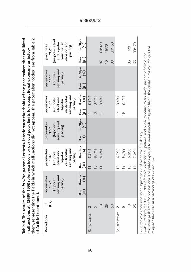
66
5 results
Wav
efo
rmf
(Hz)
pac
emak
er
“B2”
(b
ipo
lar
sen
sin
g a
nd
p
acin
g)
pac
emak
er
“B4”
(un
ipo
lar
atri
al a
nd
b
ipo
lar
ven
tric
ula
r se
nsi
ng
an
d
pac
ing
)
pac
emak
er
“B5”
(bip
ola
r se
nsi
ng
an
d
pac
ing
)
pac
emak
er
“B6”
(un
ipo
lar
atri
al a
nd
b
ipo
lar
ven
tric
ula
r se
nsi
ng
an
d
pac
ing
)
pac
emak
er
“C1”
(bip
ola
r se
nsi
ng
an
d
pac
ing
)
pac
emak
er
“C2”
(un
ipo
lar
atri
al
and
bip
ola
r ve
ntr
icu
lar
sen
sin
g a
nd
p
acin
g)
Brm
s (µ
T)B
occ/B
pu
b
(%)
Brm
s (µ
T)B
occ/B
pu
b
(%)
Brm
s (µ
T)B
occ/B
pu
b
(%)
Brm
s (µ
T)B
occ/B
pu
b
(%)
Brm
s (µ
T)B
occ/B
pu
b
(%)
Brm
s
(µT)
Bo
cc/B
pu
b
(%)
Ram
p-w
aves
211
8.3/
4111
8.3/
41
510
8.4/
4110
8.4/
41
1011
8.4/
4111
8.4/
4187
64/3
20
2519
16/7
9
5033
30/1
50
Squa
re-w
aves
215
6.7/
3319
8.4/
41
515
6.7/
3319
8.4/
41
1015
6.8/
3336
16/8
1
2514
7.0/
3466
33/1
70
Brm
s is
the
calc
ulat
ed r
oot-
mea
n-sq
uare
val
ue o
f m
agne
tic f
lux
dens
ity.
Bocc/B
pub
refe
rs t
o th
e IC
NIR
P 19
98 r
efer
ence
leve
ls f
or o
ccup
atio
nal a
nd p
ublic
exp
osur
e to
sin
usoi
dal m
agne
tic f
ield
s or
the
m
axim
um p
eak
limits
for
occ
upat
iona
l and
pub
lic e
xpos
ure
to n
on-s
inus
oida
l mag
netic
fie
lds.
The
val
ues
in t
he c
olum
n gi
ve t
he
mag
netic
fie
ld u
sed
as a
per
cent
age
of B
occ a
nd B
pub .
Tab
le 4
. Th
e re
sult
s o
f th
e in
vit
ro p
acem
aker
tes
ts. I
nte
rfer
ence
th
resh
old
s o
f th
e p
acem
aker
s th
at e
xhib
ited
m
alfu
nct
ion
s at
ICN
IRP
1998
ref
eren
ce le
vels
or
der
ived
pea
k lim
its
for
occ
up
atio
nal
exp
osu
re o
r b
elo
w
them
, rep
rese
nti
ng
th
e fi
eld
s in
wh
ich
mal
fun
ctio
ns
did
no
t ap
pea
r. Th
e p
acem
aker
“co
des
” ar
e fr
om
Tab
le 2
o
f A
rtic
le I
(co
nti
nu
ed).

67
5 results
Two of the three bipolar pacemakers that malfunctioned, INSIGNIA I AVT VDD 0882 and PULSAR MAX II DR DDDR 1280, exhibited false ventricular tachycardia detections and atrial tachycardia detections/responses. The third bipolar pacemaker, ZEPHYR XL DR5826, experi-enced mode switch episodes. An example of INSIGNIA’s false detection of ventricular tachycardia is shown in Figure 6.
Figure 6. Ventricular tachycardia detection leading to complete loss of pac-ing with pacemaker INSIGNIA I AVT VDD 0882, using sine wave with 50 Hz and 500 µT (= 100% of the ICNIRP’s 1998 reference level for occupational exposure). (VP = ventricular pacing, VS = ventricular sensing)
Two of the three unipolar pacemakers showing malfunctioning were of the same model, PULSAR MAX II DR DDDR 1280, and programmed in the same way. They experienced EMI, atrial tachycardia detection and response, quite similarly. The third unipolar pacemaker, VICTORY XL DR 5816, experienced mode switch episodes and with almost completely different magnetic fields than the other two unipolar pacemakers that malfunctioned.
Most of the EMI occurred when the pacemaker (generator case and the area formed by its electrode leads) was perpendicular to the external magnetic field, e.g., the magnetic field was applied from direction z as
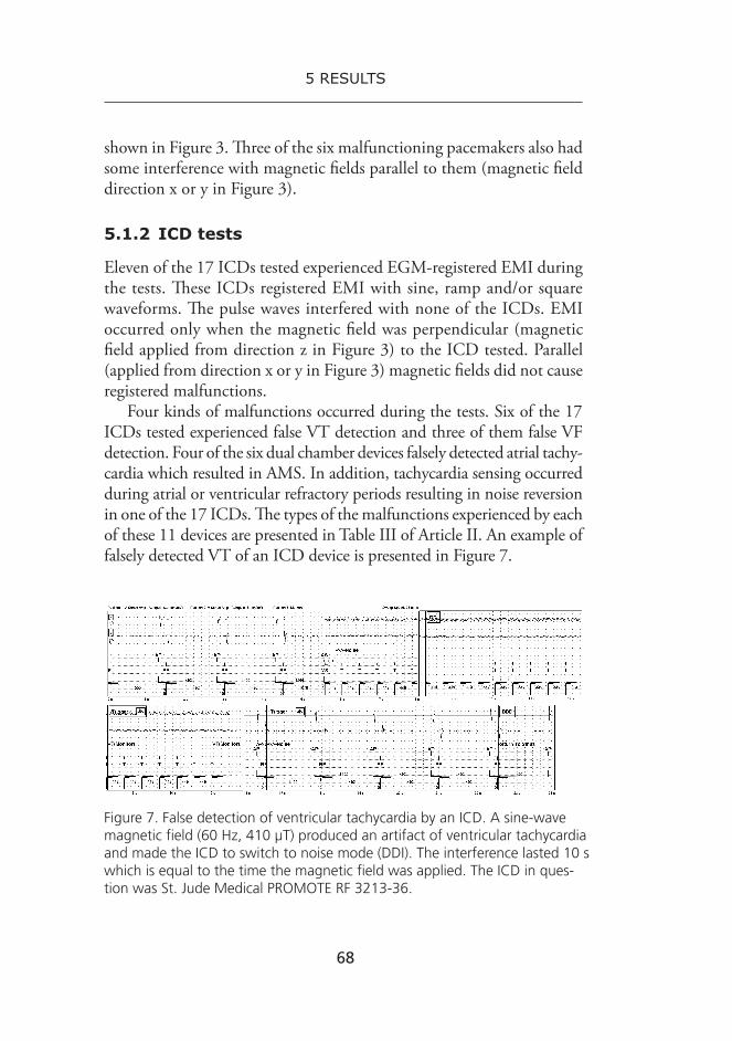
68
5 results
shown in Figure 3. Three of the six malfunctioning pacemakers also had some interference with magnetic fields parallel to them (magnetic field direction x or y in Figure 3).
5.1.2 ICD tests
Eleven of the 17 ICDs tested experienced EGM-registered EMI during the tests. These ICDs registered EMI with sine, ramp and/or square waveforms. The pulse waves interfered with none of the ICDs. EMI occurred only when the magnetic field was perpendicular (magnetic field applied from direction z in Figure 3) to the ICD tested. Parallel (applied from direction x or y in Figure 3) magnetic fields did not cause registered malfunctions.
Four kinds of malfunctions occurred during the tests. Six of the 17 ICDs tested experienced false VT detection and three of them false VF detection. Four of the six dual chamber devices falsely detected atrial tachy-cardia which resulted in AMS. In addition, tachycardia sensing occurred during atrial or ventricular refractory periods resulting in noise reversion in one of the 17 ICDs. The types of the malfunctions experienced by each of these 11 devices are presented in Table III of Article II. An example of falsely detected VT of an ICD device is presented in Figure 7.
Figure 7. False detection of ventricular tachycardia by an ICD. A sine-wave magnetic field (60 Hz, 410 µT) produced an artifact of ventricular tachycardia and made the ICD to switch to noise mode (DDI). The interference lasted 10 s which is equal to the time the magnetic field was applied. The ICD in ques-tion was St. Jude Medical PROMOTE RF 3213-36.

69
5 results
All recorded malfunctions of the ICDs occurred above the ICNIRP reference levels for general public or above peak levels derived from them [ICNIRP 1998]. The interference threshold levels that did not cause EMI with any of the ICDs tested are presented in Table 5.
f (Hz) Sine-wave Ramp-wave Square-wave
Brms (µT)
Bocc/Bpub (%) Brms (µT)
Bocc/Bpub (%) Brms (µT)
Bocc/Bpub (%)
2 83 65/320 140 65/320
5 41 33/160 70 33/160
10 570 23/110 45 33/160 70 33/160
25 390 39/200 74 64/320 140 68/340
50 180 36/180 99 91/450 120 67/330
60 170 41/200 95 89/440 110 67/330
80 160 51/260 87 85/420 100 66/330
100 180 72/360 95 65/330
Brms is the calculated root-mean-square value of magnetic field flux density.Bocc/Bpub refers to the ICNIRP 1998 reference levels for occupational and public exposure to sinusoidal magnetic fields or the maximum peak limits for occupational and public exposure to non-sinusoidal magnetic fields. The values in the column give the magnetic field used as a percentage of Bocc and Bpub.
Table 5. The results of the in vitro ICD tests. Interference threshold levels for the ICDs that exhibited malfunctions at ICNIRP 1998 reference levels or derived peak limits for occupational exposure or below them, representing the fields in which malfunctions did not appear with any of the ICDs tested.
5.2 In vivo studies
5.2.1 laboratory tests
The laboratory tests, conducted with the volunteers of the first group, did not lead to any detected EMI between the magnetic fields and bipolar pacemakers or ICDs.

70
5 results
However, all of the three pacemakers of volunteers 3, 5, and 8, pro-grammed with unipolar sensing settings experienced EMI in Exposure Set-up III. The unipolar pacemaker of Volunteer 3 experienced intermit-tent and complete ventricular pacing at maximum tracking rate due to inappropriate atrial sensing during exposure to 25 Hz sine waves and to ramp and square waves at 2 and 5 Hz. These malfunctions were ob-served in the ECG. The unipolar pacemaker of Volunteer 5 experienced intermittent or complete loss of pacing due to inappropriate ventricular sensing during exposure to 25 and 50 Hz sine waves, 2, 5, 10, and 25 Hz ramp waves and 2, 5, and 10 Hz square waves. Ventricular tachycar-dia detections were also found in the stored EGM recordings. One of these VT detections is presented in Figure 8. The unipolar pacemaker of Volunteer 8 experienced EMI during the whole exposure in Exposure Set-up III. Complete or intermittent loss of pacing due to inappropriate ventricular sensing was found in the ECG during every exposure period in Exposure Set-up III. These were seen as inappropriate AMS episodes, reversions to noise mode, and detections of high ventricular rate in stored EGM. One of these noise mode reversions is presented in Figure 9.
Figure 8. Inappropriate ventricular tachycardia detection and complete loss of pacing stored in EGM due to inappropriate ventricular sensing in Expo-sure Set-up III with the unipolarly programmed pacemaker of Volunteer 5.

71
5 results
Figure 9. Stored EGM showing inappropriate atrial and ventricular sensing episode resulting first in loss of pacing and then causing reversion to noise mode (DOO pacing) and an inappropriate AMS episode during Exposure Set-up III with the pacemaker of Volunteer 8 programmed to unipolar sens-ing settings.
5.2.2 Electronic article surveillance (EAs) gate, induction hob and MIg-welding machine
No malfunctions were detected in the bipolar pacemakers or ICDs of the first group of volunteers during the tests with the EAS gate, induction hob or welding cable.
However, the pacemaker of Volunteer 8 experienced EMI with the EAS gate and the welding cable when programmed with unipolar sens-ing settings. The ECG showed inappropriate atrial sensing, resulting in ventricular pacing at the maximum tracking rate, when the volunteer was walking past the EAS gate. However, this did not happen when the volunteer stood in front of the gate for 1 min. During exposure to the welding cable, the pacemaker of Volunteer 8 sensed atrial signals inap-propriately, resulting first in ventricular pacing at maximum tracking rate and later in an AMS episode seen in the stored EGM. The volunteer also reported a heavy feeling in her chest. Due to the subjective feelings of the volunteer, the test was discontinued after two welding periods. The maximum magnetic flux densities measured during these two welding periods were 130 and 100 µT.
The unipolarly programmed pacemakers of Volunteers 3 and 5 did not experience any malfunction during the tests with the EAS gate, induction hob or welding cable. The unipolar pacemaker of Volunteer 8 also functioned flawlessly during the induction hob test.

72
5 results
5.2.3 Two mobile phone base stations, electric commuter train, overhead 400 kv high voltage transmission lines
During the exposure to the mobile phone base stations, commuter train, and transmission lines, none of the pacemakers of the second group of volunteers experienced EMI that could be observed from the continuous ECG recordings or from the stored EGMs.
5.2.4 laptop-computer
The ICD tested experienced EMI soon after the laptop-computer was placed on the chest of the volunteer. The ICD started to make the beeping sound and went into magnet mode. This malfunction occurred without any network connections on. When the experiment was repeated with a WLAN connection, the result was the same. As EMI occurred also without the WLAN connection, it was concluded that it was caused by the static magnetic field generated by the hard disk of the laptop. After the laptop was moved away from the ICD, the beeping stopped and the ICD returned to its normal mode. The conversion to magnet mode is the expected response of an ICD when a sufficiently large permanent magnet is situated above it.
73
6 dIscussIon
Studies testing electromagnetic interference in pacemakers and ICDs have usually focused on a specific application, such as mobile phones, EAS gates or medical equipment. Studies with low frequency magnetic fields (excluding power line frequencies 50/60 Hz) are rare. Many stud-ies have focused on sinusoidal waveforms and have seldom considered pulsed waves, although often the fields in industrial workplaces are non-sinusoidal. However, there is a lack of knowledge of pacemaker/ICD EMI in low frequency magnetic fields and especially with non-sinusoidal waveforms. This study tried to give insight into possible EMI in these conditions and with some common occupational applications.
With the pacemakers tested in vitro, the malfunctions found were inap-propriate detections of atrial and ventricular tachycardia and auto mode switch episodes. In false tachycardia detection, the pacemaker interprets external signals as intrinsic heartbeats. This can result in induction of real arrhythmias and/or bradycardia leading to asystole. It can also cause symptoms such as palpitations, low blood pressure and chest pain. Before a false AMS episode, the pacemaker interprets an external signal as atrial arrhythmia, which leads to the activation of AMS usually resulting in ventricular pacing. Atrial or ventricular pacing during inappropriate AMS can lead to asynchronous atrial pacing in DDI mode and asynchronous ventricular pacing in VVI mode, respectively. In addition, it can cause, though very rarely, arrhythmias and pump failure (pacemaker syndrome).
None of the bipolar pacemakers of the volunteers tested in vivo ex-perienced EMI during exposures to any of the waveforms of Exposure Set-ups I–III. However, only one of the 11 pacemakers tested in vivo were of exactly the same model as the three pacemakers that malfunctioned in the in vitro tests.

74
6 discussion
Three pacemakers with unipolar atrial sensing and pacing were tested in vitro; they all experienced EMI resulting in atrial tachycardia detec-tions and AMS. The three unipolar pacemakers tested in vivo using low frequency magnetic fields experienced inappropriate atrial or ventricular sensing resulting in ventricular pacing at the maximum tracking rate and in loss of pacing. In the electrogram records stored, these malfunctions were seen as ventricular tachycardia detections, AMS episodes, rever-sion to noise mode and ventricular higher rate detections. The unipolar pacemakers experienced same kinds of malfunctions both in vitro and in vivo during exposures to low frequency magnetic fields, even though none of the devices were of the same model.
The malfunctions detected during the in vitro laboratory tests with the ICDs were false ventricular tachycardia and fibrillation detections, false detection of atrial tachycardia resulting in AMS, and tachycardia detection during atrial or ventricular refractory period resulting in noise reversion. In inappropriate VT or VF detection, the ICD interprets external signal as rapid intrinsic heartbeats and activates arrhythmia termination either by anti-tachycardia pacing or by a high voltage therapy shock. ATP and therapy shocks can induce real arrhythmias and, in addition, therapy shocks are usually extremely uncomfortable when received in a conscious state. In false AMS, the ICD interprets external signal as atrial arrhythmias and it results in asynchronous atrial or ventricular pacing, like in bradycardia pacemakers. In noise reversion, the inappropriate tachycardia detection during refractory period results also in inappropriate asynchronous pacing. None of these, or any other malfunctions could be detected in the in vivo laboratory tests, although the magnetic field intensities used in the in vivo Exposure Set-ups II and III were generally much higher than the field levels that induced EMI in ICDs in vitro using the same waveforms and frequencies. However, only two of the ICDs that malfunctioned in vitro were exactly the same models as those tested in vivo.
The major differences in results between the in vitro and in vivo tests raise a question about the use of these kinds of phantoms in EMI tests of pacemakers and ICDs. How reliable are the results obtained with phan-tom tests using this kind of simple, electrically passive phantom and with phantom tests in general? One possibility could be to tests pacemakers/ICDs in vivo right before the explantation of the device during the device

75
6 discussion
replacement and repeat the test in vitro with exactly same settings right after the explantation using different kinds of phantoms. This procedure could give valuable information about the validity of phantom tests and could help to improve phantom testing.
The EMI with an ICD was found in the case of laptop computer situated on the ICD and made the ICD convert to magnet mode. The test indicates that people with an ICD may be at serious risk during the common habit of lying on a bed and using a laptop. Standard EN 50527-1 regards computers and other IT equipment (radio transmission equipment and wireless communication excluded) as compliant with active implanted medical devices [CENELEC 2010]. Static magnetic fields usually have a temporary effect of converting ICDs to magnet mode. However, in some ICD models the effects of static magnetic fields can be permanent. With certain programming in some ICD models, arrhythmia detection and therapy can be permanently deactivated in 30 seconds by a magnet. This can cause a serious risk to the health and life of a person with an ICD [Rasmussen et al. 2002; Hauser et al. 2004].
The appliances chosen for this study to test pacemaker/ICD EMI in real life situations (EAS gate, induction hob, welding cable, mobile phone base stations, electric commuter train, and high voltage power lines) were among those that have previously been reported to cause interference with implanted devices or that raise questions about pacemaker/ICD safety. Though they do not emit the highest EMFs that can be found at workplaces, they all are common applications of various occupational environments. Check-outs in many stores are positioned close to EAS gates and cashiers stand or sit next to them during their entire work shift. Induction cooking/heating and welding are widely used in several occu-pations. EMF exposure from mobile base stations may not be relevant to most workers, because base stations antennas are normally located near the roof, far away from normal working environments. However, areas with field levels similar to those measured in this study may be accessed by technical personnel installing and maintaining the base stations. Public transportation, like commuter trains, is a global source of EMFs to both, employees and passengers, and high voltage transmission lines can produce relatively high electric and magnetic fields in the surround-ing area and below. These fields emitted by power lines are reported as possibly interfering with the operation of pacemakers [Toivonen et al.
76
6 discussion
1991; Trigano et al. 2005B; Della Chiara et al. 2007; Korpinen et al. 2012]. This can cause EMI with a pacemaker of a worker maintaining the lines. Although no traces of EMI was found between the transmission lines and the pacemakers tested in this study, high voltage transmission lines still remain a potential source of EMI.
The unipolar pacemakers tested in this study, both in vitro and in vivo, were found to be more susceptible to external EMFs than the pacemakers tested with bipolar settings. This finding is consistent with the results of several other studies [Toivonen et al 1991; Wilke et al. 1998; Trigano et al. 2005B; Della Chiara et al. 2007]. However, in vitro laboratory studies with low frequency magnetic fields also showed EMI in bipolar pacemakers at quite low field intensities. Although no pacemaker/ICD malfunctioning was found in in vivo tests in the relatively high magnetic fields used, the new ICNIRP guideline of 1 000 µT for occupational exposure (at 50 Hz) may be too high for most workers with a pacemaker/ICD [ICNIRP 2010]. The results of the in vivo tests of this study indicate that in the case of a worker with a bipolar pacemaker or an ICD, the exposure limits for the general public given by the European Council Recommendation (1999/519/EC) could be applied [The Council of the European Union 1999]. However, when a worker receives a unipolar pacemaker a more specific risk assessment is needed when the EMFs in the workplace are near or exceed the exposure limits for the general public. The magnetic flux densities that were used in this study to expose the unipolar pacemakers in vivo were much higher than the ICNIRP 1998 guidelines for public exposure [ICNIRP 1998]. Hence, more in vivo research is needed before these public exposure limits can be used as “safety-levels” with unipolar pacemakers.

77
7 conclusions
The volunteer tests with cardiac pacemakers and ICDs indicate that modern arrhythmia devices are well shielded against low frequency magnetic fields even at electromagnetically hostile workplaces. Unipo-lar pacemakers were found to be much more sensitive to the magnetic fields applied in both, in vitro and in vivo laboratory tests than bipolar devices. The appliances tested – EAS gate, induction hob, MIG-welding cable, mobile phone base stations, electric commuter train, and 400 kV transmission power lines – do not seem to pose a high health risk with modern bipolar pacemakers. Unipolar pacemakers, on the other hand, can be affected by EMFs of common everyday applications, such as EAS gates at stores, and thus should be avoided when possible. The findings of the in vitro tests, however, leave questions about the possibility of EMI even with bipolar pacemakers and ICDs.
Laptop computers, positioned above the chest, can cause EMI with ICDs as shown by the findings of this study.
The results indicate that the commonly used magnetic field “safety-limit” for pacemakers, corresoponding to the 1998 ICNIRP reference level for public exposure, B=100 µT (at 50 Hz), may be too high, espe-cially for unipolar pacemakers. Based on the results of this study, it is not possible to derive general “safety-limits” or thresholds for EMI on pacemakers and ICDs. Each device needs to be programmed individually, and each patient as well as the work environment is different. In addition to intensity, the occurrence of EMI depends greatly on the frequency, waveform, and direction of the external electromagnetic field. Also the person’s dependency on the pacemaker and the severity of possible device malfunctions to his/her cardiac condition are important aspects when evaluating the consequences of EMI. Due to this, an individual

78
7 conclusions
health risk assessment needs to be carried out in the workplace for every worker returning to work after a pacemaker or ICD implantation. In most workplaces such risk assessments will be rather straightforward, as workplace EMFs are in general much lower than those tested and found not to interfere with bipolar pacemakers and ICDs in the in vivo tests of this study.

79
8 referencesAbdelmalak B, Jagannathan N, Arain FD, Cymbor S, McLain R, Tetzlaff JE. Electromagnetic
interference in a cardiac pacemaker during cauterization with the coagulating, not cutting mode. J Anaesthesiol Clin Pharmacol 2011;27:527–530.
Alanko T, Hietanen M, von Nandelstadh P. Occupational exposure to RF fields from base station antennas on rooftops. Ann Telecommun 2008;63:125–132.
Al Khadra AS, Al Jutaily A, Al Shuhri S. Detection of refrigerator-associated 60 Hz alternating current as ventricular fibrillation by an implantable defibrillator. Europace 2006;8:175–177.
Allen M. Pacemakers and implantable cardioverter defibrillators. Anaesthesia 2006;61:883–890.
Altamura G, Toscano S, Gentilucci G, Ammirati F, Castro A, Pandozi C et al. Influence of digital and analogue cellular telephones on implanted pacemakers. Eur Heart J 1997;18:1632–1641.
Ambardekar AV, Lowery CM, Allen LA, Cannon AP, Cleveland JC Jr., Lindenfeld J et al. Effect of left ventricular assist device placement on preexisting implantable cardioverter-defibrillator leads. J Cardiac Fail 2010;16:327–331.
Anderson DR, Gillberg JM, Torrey JW, Koneru JN. Lightning induced inappropriate ICD shock: An unusual case of electromagnetic interference. Pacing Clin Electrophysiol 2012;35:e159–e162.
Angeloni A, Barbaro V, Bartolini P, Calcagnini G, Censi F. A novel heart/trunk simulator for the study of electromagnetic interference with active implantable devices. Med Biol Eng Comput 2003;41:550–555.
Annila M. Sydäntahdistimien ja rytmihäiriötahdistimien häiriintymisen mittaaminen voima-johdon alla. Diplomityö. Tampereen teknillinen yliopisto, 2010. Page 7. (in Finnish)
Bakhtiary F, Therapidis P, Scherer M, Dzemali O, Moritz A, Kleine P. Electromagnetic interaction between an axial left ventricular assist device and an implantable cardioverter defibrillator. J Thorac Cardiovasc Surg 2008;136:1380–1381.
Barbaro V, Bartolini P, Bellocci F, Caruso F, Donato A, Gabrielli D et al. Electromagnetic interfer-ence of digital and analog cellular telephones with implantable cardioverter defibrillators: In vitro and in vivo studies. Pacing Clin Electrophysiol 1999;22[Pt. I]:626–634.

80
8 references
Bassen HI, Moore HJ, Ruggera PS. Cellular phone interference testing of implantable cardiac defibrillators in vitro. Pacing Clin Electrophysiol 1998;21:1709–1715.
Bassen H. Low frequency magnetic emissions and resulting induced voltages in a pacemaker by iPod portable music players. Biomed Eng Online 2008;7:7.
Beirnart R, Guy ML, Ellinor PT. Intermittent, erratic behavior of an implantable car-dioverter defibrillator secondary to a hidden magnetic source of interference. Europace 2011;13:1508–1509.
Bernstein AD, Camm AJ, Fletcher RD, Gold RD, Richards AF, Smyth NP et al. The NASPE/BPEG generic pacemaker code for antibradyarrhythmia and adaptive-rate pacing and antitachyarrhythmia devices. Pacing Clin Electrophysiol 1987;10[Pt. 1]:794–799.
Bernstein AD, Daubert J-C, Fletcher RD, Hayes DL, Lüderitz B, Reynolds DW et al. The revised NASPE/BPEG generic code for antibradycardia, adaptive-rate and multisite pacing. Pacing Clin Electrophysiol 2002;25:260–264.
Bolte JFB and Pruppers MJM. Electromagnetic fields in the working environment. Ministry of Social Affairs and Employment (SZW) Report. 2006. Pages: 35, 38, 50–51.
Boston Scientific, Medtronic, St. Jude Medical. Personal information from the technical services concerning electromagnetic compatibility of pacemakers and implantable cardioverter-defibrillators. 2012.
Brand HS, Entjes ML, Nieuw Amerongen AV, van der Hoeff EV, Schrama TAM. Interference of electrical dental equipment with implantable cardioverter-defibrillators. Br Dent J 2007;203:577–579.
Bristow MR, Saxon LA, Boehmer J, Krueger S, Kass DA, De Marco T et al. Cardiac-resynchro-nization therapy with or without an implantable defibrillator in advanced chronic heart failure. N Engl J Med 2004;350:2140–2150.
Burke MC, Kopp DE, Alberts M, Patel A, Lin AC, Kall JG et al. Effect of radiofrequency current on previously implanted pacemaker and defibrillator lead systems. J Electrocardiol 2001;34 (Suppl): 143–148.
Cao M, Shinbane JS, Gillberg JM, Saxon LA. Taser-induced rapid ventricular myocardial capture demonstrated by pacemaker intracardiac electrograms. J Cardiovasc Electrophysiol 2007;18:876–879.
Carlson T, Andréll P, Ekre O, Edvarsson N, Holmgren C, Jacobsson F et al. Interference of transcutaneous electrical nerve stimulation with permanent ventricular stimulation: A new clinical problem? Europace 2009;11:364–369.
Casavant D, Haffajee C, Stevens S, Pacetti P. Aborted implantable cardioverter-defibrillator shock during facial electrosurgery. Pacing Clin Electrophysiol 1998;21:1325–1326.
CDRH Magnetic Resonance Working Group. A primer on medical device interactions with magnetic resonance imaging systems. 1997. Available at: http://www.fda.gov/MedicalDe-vices/DeviceRegulationandGuidance/GuidanceDocuments/ucm107721.htm. Accessed May 3, 2013.

81
8 references
CENELEC, European Committee for Electrotechnical Standardization. EN 50527-1. Procedu-re for the assessment of the exposure to electromagnetic fields of workers bearing active implantable medical devices-Part 1: General. Brussels, Belgium; 2010.
Chan NY and Ho LW-L. Inappropriate implantable cardioverter-defibrillator shock due to external alternating current leak: Report of two cases. Europace 2005;7:193–196.
Cheng A, Nazarian S, Spragg DD, Bilchick K, Tandri H, Mark L, et al. Effects of surgical and endoscopic electrocautery on modern-day permanent pacemaker and implantable cardioverter-defibrillator systems. Pacing Clin Electrophysiol 2008;31:344–350.
Chiladakis JA, Davlouros P, Agelopoulos G, Manolis AS. In vivo testing of digital cellu-lar telephones in patients with implantable cardioverter-defibrillators. Eur Heart J 2001;22:1337–1342.
Chongtham DS, Bahl A, Kumar RM, Talwar KK. Inappropriate shock delivered by implantable cardioverter defibrillator due to electrical interference with washing machine. Int J Cardiol 2007;118:e44–e45.
Chung MK, Streem SB, Ching E, Grooms M, Mowrey KA, Wilkoff BL. Effects of extracorporeal shock wave lithotripsy on tiered therapy implantable cardioverter defibrillators. Pacing Clin Electrophysiol 1999;22:738–742.
The Council of the European Union. Council Recommendation of 12 July 1999 on the limitation of exposure of the general public to electromagnetic fields (0 Hz to 300 GHz) (1999/519/EC). Official J Eur Communities 1999;L 199:59–70.
Cowger Matthews J, Betley D, Morady F, Pelosi Jr. F. Adverse interaction between a left ventri-cular assist device and an implantable cardioverter defibrillator. J Cardiovasc Electrophysiol 2007;18:1107–1108.
Crevenna R, Stix G, Pleiner J, Pezawas T, Schmidinger H, Quittan M et al. Electromagnetic interference by transcutaneous neuromuscular electrical stimulation in patients with bipolar sensing implantable cardioverter defibrillators: A pilot safety study. Pacing Clin Electrophysiol 2003;26[Pt. I]:626–629.
Cronin EM, Gray J, Abi-Saleh B, Wilkoff BL, Levin KH. Safety of repetitive nerve stimulation in patients with cardiac implantable electronic devices. Muscle Nerve 2013;47:840–844.
Della Chiara G, Primiani VM, Moglie F. Experimental and numeric investigation about electro-magnetic interference between implantable cardiac pacemaker and magnetic fields at power line frequency. Ann Ist Super Sanità 2007;43:248–253.
Dubner S, Dubner Y, Gallino S, Spallone L, Zagalsky D, Rubio H et al. Electromagnetic interference with implantable cardiac pacemakers by video capsule. Gastrointest Endosc 2005;61:250–254.
Dubner S, Dubner Y, Rubio H, Goldin E. Electromagnetic interference from wireless video-capsule endoscopy on implantable cardioverter-defibrillators. Pacing Clin Electrophysiol 2007;30:472–475.

82
8 references
Dyrda K and Khairy P. Implantable rhythm devices and electromagnetic interference: myth or reality? Expert Rev Cardiovasc Ther 2008;6:823–832.
Elshershari H, Çeliker A, Özer S, Özme Ş. Influence of D-Net (EUROPEAN GSM-Standard) cellular telephones on implanted pacemakers in children. Pacing Clin Electrophysiol 2002;25:1328–1330.
Engelhardt L, Große J, Birnbaum J, Volk T. Inhibition of a pacemaker during nerve stimulation for regional anaesthesia. Anaesthesia 2007;62:1071–1074.
European Parliament and Council. Directive 2004/40/EC of the European Parliament and the Council on the minimum health and safety requirements regarding the exposure of workers to the risks arising from the physical agents (electromagnetic fields). Official J Eur Union 2004;L 159:1–26.
European Parliament and Council. Directive 2013/35/EU of the European Parliament and the Council on the minimum health and safety requirements regarding the exposure of workers to the risks arising from physical agents (electromagnetic fields). Official J Eur Union 2013;L 179:1–21.
Fernengel A, Schwer C, Helber U, Dörnberger V. Inappropriate implantable cardioverter-defibrillator shock induced by electromagnetic interference while taking a shower. Clin Res Cardiol 2007;96:393–395.
Fiek M, Remp T, Reithmann C, Steinbeck G. Complete loss of ICD programmability after magnetic resonance imaging. Pacing Clin Electrophysiol 2004;27:1002–1004.
Foo D, Walker BD, Kuchar DL, Thorburn CW, Tay A, Hayward CS et al. Left ventricular mechanical assist devices and cardiac device interactions: An observational case series. Pacing Clin Electrophysiol 2009;32:879–887.
Forleo GB, Santini L, Della Rocca DG, Romano V, Papavasileiou LP, Magliano G et al. Safety and efficacy of a new magnetic resonance imaging-compatible pacing system: Early results of a prospective comparison with conventional dual-chamber implant outcomes. Heart Rhythm 2010;7:750–754.
Frank R, Souques M, Himbert C, Hidden-Lucet F, Petitot JC, Fontaine G, et al. Effects of 50 to 60 Hz and of 20 to 50 kHz magnetic fields on the operation of implanted cardiac pacemakers. Arch Mal Coeur Vaiss 2003;96:35–41. (abstract)
Fukuta M, Mizutani N, Waseda K. Influence of electromagnetic interference on implanted cardiac arrhythmia devices in and around a magnetically levitated linear motor car. J Artif Organs 2005;8:154–160.
Garg A, Wadhwa M, Brown K, Luckett C, Vaughn T, Birgersdotter-Green U et al. Inappropriate implantable cardioverter defibrillator discharge from sensing of external alternating current leak. J Interv Card Electrophysiol 2002;7:181–184.
Garofalo RR, Ede EN, Dorn SO, Kuttler S. Effect of electronic apex locators on cardiac pace-maker function. J Endod 2002;28:831–833.
Gimbel JR, Kanal E, Schwartz KM, Wilkoff BL. Outcome of magnetic resonance imaging (MRI) in selected patients with implantable cardioverter defibrillators (ICDs). Pacing Clin Electrophysiol 2005;28:270–273.

83
8 references
Gimbel JR and Cox JW Jr. Electronic article surveillance systems and interactions with implant-able cardiac devices: Risk of adverse interactions in public and commercial spaces. Mayo Clin Proc 2007;82:318–322.
Gimbel JR. Magnetic resonance imaging of implantable cardiac rhythm devices at 3.0 Tesla. Pacing Clin Electrophysiol 2008;31:795–801.
Gimbel JR. Unexpected asystole during 3T magnetic resonance imaging of a pacemaker-dependent patient with a ‘modern’ pacemaker. Europace 2009;11:1241–1242.
Glotzer TV, Gordon M, Sparta M, Radoslovich G, Zimmerman J. Electromagnetic interference from a muscle stimulation device causing discharge of an implantable cardioverter defibril-lator: Epicardial bipolar and endocardial bipolar sensing circuits are compared. Pacing Clin Electrophysiol 1998;21:1996–1998.
Goldstein DJ, Oz MC, Rose EA. Implantable left ventricular assist devices. New Engl J Med 1998;339:1522–1533.
Gomez G, Duran-Sindreu F, Clemente J, Garofalo RR, Garcia M, Bueno R et al. The effects of six electronic apex locators on pacemaker function: an in vitro study. Int Endod J 2013;46:399–405.
Götte MJW, Rüssel IK, de Roest GJ, Germans T, Veldkamp RF, Knaapen P, et al. Magnetic resonance imaging, pacemakers and implantable cardioverter-defibrillators: Current situ-ation and clinical perspective. Neth Heart J 2010;18:31–37.
Groh WJ, Boschee SA, Engelstein ED, Miles WM, Burton ME, Foster PR, et al. Interactions between electronic article surveillance systems and implantable cardioverter-defibrillators. Circulation 1999;100:387–392.
Gustrau F, Bahr A, Goltz S, Eggert S. Active medical implants and occupational safety measure-ment and numerical calculation of interference voltage. Biomed Tech (Berl) 2002;47(Suppl. 1, Pt. 2):656–659.
Gwechenberger M, Rauscha F, Stix G, Schmid G, Strametz-Juranek J. Interference of program-med electromagnetic stimulation with pacemakers and automatic implantable cardioverter defibrillators. Bioelectromagnetics 2006;27:365–377.
Haegeli LM, Sterns LD, Adam DC, Leather RA. Effect of a Taser shot to the chest of a patient with an implantable defibrillator. Heart Rhythm 2006;3:339–341.
Hartikainen J. Tahdistinhoidon periaatteet hitaan sydämen tahdistuksessa. In book: Mäkijärvi M, Kettunen R, Kivelä A, Parikka H, Yli-Mäyry S edit. Sydänsairaudet. Helsinki: Kustannus Oy Duodecim, 2008. Pages: 481–482. (in Finnish)
Hauser RG and Kallinen L. Deaths associated with implantable cardioverter defibrillator failure and deactivation reported in the United States Food and Drug Administration Manufacturer and User Facility Device Experience Database. Heart Rhythm 2004;4:399–405.
Hayes DL, Wang PJ, Reynolds DW, Estes M III, Griffith JL, Steffens RA et al. Interference with cardiac pacemakers by cellular telephones. New Engl J Med 1997;336:1473–1479.

84
8 references
Heatlie G and Pennell DJ. Cardiovascular magnetic resonance at 0.5T in five patients with permanent pacemakers. J Cardiovasc Magn Reson 2007;9:15–19.
Hekmat K, Salemink B, Lauterbach G, Schwinger RHG, Südkamp M, Weber HJ et al. Inter-ference by cellular phones with permanent implanted pacemakers: an update. Europace 2004;6:363–369.
Hietanen M, Hämäläinen A-M, von Nandelstadh P. Electromagnetic fields in the work environ-ment. Finnish Institute of Occupational Health; Helsinki, 2002.
Hirose M, Hida M, Sato E, Kokubo K, Nie M, Kobayashi H. Electromagnetic interference of implantable unipolar cardiac pacemakers by an induction oven. Pacing Clin Electrophysiol 2005;28:540–548.
Hocking B and Hansson Mild K. Guidance note: Risk management of workers with medical electronic devices and metallic implants in electromagnetic fields. Int J Occup Saf Ergon 2008;14:217–222.
Holmgren C, Carlsson T, Mannheimer C, Edvardsson N. Risk of interference from transcuta-neous electrical nerve stimulation on the sensing function on implantable defibrillators. Pacing Clin Electrophysiol 2008;31:151–158.
Huikuri H and Raatikainen P. Rytmihäiriötahdistinhoito. In book: Heikkilä J, Kupari M, Airaksinen J, Huikuri H, Nieminen MS, Peuhkurinen K, edit. Kardiologia. 2., uudistettu painos. Helsinki: Kustannus Oy Duodecim, 2008. Pages: 677–685. (in Finnish)
International Commission on Non-Ionizing Radiation Protection (ICNIRP). Guidelines for limiting exposure to time-varying electric, magnetic, and electromagnetic fields (up to 300 GHz). Health Phys 1998;74:494–522.
International Commission on Non-Ionizing Radiation Protection (ICNIRP). ICNIRP statement related to the use of security and similar devices utilizing electromagnetic fields. Health Phys 2004;87:187–196.
International Commission on Non-Ionizing Radiation Protection (ICNIRP). Guidelines for limiting exposure to time-varying electrical and magnetic fields (1 Hz to 100 kHz). Health Phys 2010;99:818–836.
International Commission on Non-Ionizing Radiation Protection (ICNIRP) and World Health Organization (WHO). Health effects of electromagnetic fields in the frequency range 300 Hz to 10 MHz. Proceedings: International seminar on health effects of exposure to electromagnetic fields in the frequency range 300 Hz to 10 MHz, Maastricht, Netherlands; June 7 and 8, 1999. Pages: 21–25.
Irnich W. Electronic security systems and active implantable medical devices. Pacing Clin Electrophysiol 2002;25:1235–1258.
Irnich W and Bernstein AD. Do induction cooktops interfere with cardiac pacemakers? Europace 2006;8:377–384.
Ismail MM, Badreldin AMA, Heldwein M, Hekmat K. Third-generation mobile phones (UMTS) do not interfere with permanent implanted pacemakers. Pacing Clin Electrophysiol 2010;33:860–864.

85
8 references
Jilek C, Tzeis S, Reents T, Estner H-L, Fichtner S, Ammar S et al. Safety of implantable pace-makers and cardioverter defibrillators in the magnetic field of a novel remote magnetic navigation system. J Cardiovasc Electrophysiol 2010;21:1136–1141.
Jokela K, Korpinen L, Hietanen M, Puranen L, Huurto L, Pättikangans H et al. Säteilylähteet ja altistuminen. In book: Nyberg H and Jokela K, eds. Säteily- ja ydinturvallisuus -kirjasarjan osa 6 – Sähkömagneettiset kentät. Helsinki: Säteilyturvakeskus, 2006. Pages: 385–386. (in Finnish)
Jung W, Zvereva V, Hajredini B, Jäckle S. Initial experience with magnetic resonance imaging-safe pacemakers. J Interv Card Electrophysiol 2011;32:213–219.
Kainz W, Casamento JP, Ruggera PS, Chan DD, Witters DM. Implantable cardiac pacemaker electromagnetic compatibility testing in a novel security system simulator. IEEE Trans Biomed Eng 2005;52:520–530.
Kolb C, Zrenner B, Schmitt C. Incidence of electromagnetic interference in implantable car-dioverter defibrillators. Pacing Clin Electrophysiol 2001;24[Pt. 1]:465–468.
Kolb C, Schmieder S, Schmitt C. Inappropriate shock delivery due to interference between a washing machine and an implantable cardioverter defibrillator. J Interv Card Electrophysiol 2002;7:255–256.
Kolb C, Deisenhofer I, Weyerbrock S, Schmieder S, Plewan A, Zrenner B et al. Incidence of antitachycardia therapy suspension due to magnet reversion in implantable cardioverter defibrillators. Pacing Clin Electrophysiol 2004;27:221–223.
Kolb C, Luik A, Hessling G, Zrenner B. Magnetic catheter navigation system interference with a dual-chamber pacemaker. J Cardiovasc Electrophysiol 2007;18:892–893.
Koneru JN, Dumitru I, Easley AR Jr. Electromagnetic interference from electronic article sur-veillance system in a patient with a biventricular ICD and a left ventricular assist device. Pacing Clin Electrophysiol 2011;34:244–246.
Korpinen L, Kuisti H, Elovaara J, Virtanen V. Cardiac pacemakers in electric and magnetic fields of 400-kV power lines. Pacing Clin Electrophysiol 2012;35:422–430.
Labedi MR, Alharethi R, Kfoury AG, Budge D, Bruce R, Rasmusson B et al. Electromagnetic interference of automatic implantable cardioverter defibrillator and HeartWare left vent-ricular assist device. ASAIO J 2013;59:136–139. (abstract)
Lakkireddy D, Patel D, Ryschon K, Bhateja R, Bhakru M, Thal S et al. Safety and efficacy of radiofrequency energy catheter ablation of atrial fibrillation in patients with pacemakers and implantable cardiac defibrillators. Heart Rhythm 2005;2:1309–1316.
Lee S, Fu K, Kohno T, Ransford B, Maisel WH. Clinically significant magnetic interference of implanted cardiac devices by portable headphones. Heart Rhythm 2009;6:1432–1436.
Lee SW, Moak JP, Lewis B. Inadvertent detection of 60-Hz alternating current by an implantable cardioverter defibrillator. Pacing Clin Electrophysiol 2002;25[Pt. I]:518–519.
Li H. Magnet decoration, beautiful but potentially dangerous for patients with implantable pacemakers or defibrillators. Heart Rhythm 2007;4:5–6.

86
8 references
Lin JC. Dosimetric comparison between different quantities for limiting exposure in the RF band: Rationale and implications for guidelines. Health Phys 2007;92:547–553.
Luechinger R, Duru F, Zeijlemaker VA, Scheidegger MB, Boesiger P, Candinas R. Pacemaker Reed switch behavior in 0.5, 1.5, and 3.0 Tesla magnetic resonance imaging units: Are Reed swit-ches always closed in strong magnetic fields? Pacing Clin Electrophysiol 2002;25:1419–1423.
Manolis AG, Katsivas AG, Vassilopoulos CV, Louvros NE. Implantable cardioverter defibrillator – An unusual case of inappropriate discharge during showering. J Interv Card Electrophysiol 2000;4:265–268.
Martin ET and Sandler DA. MRI in patients with cardiac devices. Curr Cardiol Rep 2007;9:63–71.
Mathew P, Lewis C, Neglia J, Krol RB, Saksena S. Interaction between electronic article sur-veillance systems and implantable defibrillators: Insight from a fourth generation ICD. Pacing Clin Electrophysiol 1997;20:2857–2859.
McIntyre WF, Michael KA, Baranchuk A. Electromagnetic interference induced by magnetic resonance imaging. Can J Cardiol 2010;26:e64.
McIvor ME, Reddinger J, Floden E, Sheppard RC. Study of pacemaker and implantable cardio-verter defibrillator triggering by electronic article surveillance devices (SPICED TEAS). Pacing Clin Electrophysiol 1998;21:1847–1861.
McIvor ME and Sridhar S. Interactions between cardiac pacemakers and antishoplifting security systems. N Engl J Med 1998;339:1394–1395.
Mehta R, Doshi AA, Hasan AK, Love CJ, Pizzuto M. Device interactions in patients with advanced cardiomyopathy. J Am Coll Cardiol 2008;51:1613–1614.
Miller CS, Leonelli FM, Latham E. Selective interference with pacemaker activity by electrical dental devices. Oral Surg Oral Med Oral Pathol Oral Radiol Endod 1998;85:33–36.
Misiri J, Kusumoto F, Goldschlager N. Electromagnetic interference and implanted cardiac devices: The medical environment (Part II). Clin Cardiol 2012;35:321–328.
Mond HG and Proclemer A. The 11th world survey of cardiac pacing and implantable cardio-verter-defibrillators: calendar year 2009-a World Society of Arrhythmia’s Project. Pacing Clin Electrophysiol 2011;34:1013–1027.
Mugica J, Henry L, Podeur H. Study of interactions between permanent pacemakers and elec-tronic antitheft surveillance system. Pacing Clin Electrohysiol 2000;23:333–337.
Naehle CP, Strach K, Thomas D, Meyer C, Linhart M, Bitaraf S et al. Magnetic resonance imaging at 1.5-T in patients with implantable cardioverter-defibrillators. J Am Coll Cardiol 2009;54:549–555.
Naehle CP, Kreuz J, Strach K, Schwab JO, Pingel S, Luechinger R et al. Safety, feasibility, and diagnostic value of cardiac magnetic resonance imaging in patients with cardiac pacemakers and implantable cardioverters/defibrillators at 1.5 T. Am Heart J 2011;161:1096–1105.
Nagatomo T, Abe H, Kohno R, Toyoshima T, Fujimoto H, Kondo S et al. Electromagnetic interference with a bipolar pacemaker by an induction heating (IH) rice cooker. Int Heart J 2009;50:133–137.

87
8 references
Nair P and Roguin A. Magnetic resonance imaging in patients with ICDs and pacemakers. Indian Pacing Electrophysiol J 2005;5:197–209.
Nercessian OA, Wu H, Nazarian D, Mahmud F. Intraoperative pacemaker dysfunction caused by the use of electrocautery during a total hip arthroplasty. J Arthroplasty 1998;13:599–602.
Occhetta E, Bortnik M, Magnani A, Francalacci G, Marino P. Inappropriate implantable cardioverter-defibrillator discharges unrelated to supraventricular tachyarrhythmias. Eu-ropace 2006;8:863–869.
Oswald H, Klein G, Strüber M, Gardiwal A. Implantable defibrillator with left ventricular assist device compatibility. Interact Cardiovasc Thorac Surg 2009;8:579–580.
Pai RK, Abedin M, Rawling DA. Inappropriate ICD shocks for inappropriate reasons. Indian Pacing Electrophysiol J 2008;8:69–71.
Pakarinen S. Sydämen vajaatoiminnan tahdistinhoito. In book: Heikkilä J, Kupari M, Airaksinen J, Huikuri H, Nieminen MS, Peuhkurinen K, edit. Kardiologia. 2., uudistettu painos. Helsinki : Kustannus Oy Duodecim 2008. Pages: 686–691. (in Finnish)
Pakarinen S and Toivonen L. Nykyaikainen tahdistinhoito. Duodecim 2010;126:757–763. (in Finnish)
Parikka H. Tahdistuksen vaikutukset sydämen toimintaan. In book: Mäkijärvi M, Kettunen R, Kivelä A, Parikka H, Yli-Mäyry S edit. Sydänsairaudet. 1. painos. Helsinki: Kustannus Oy Duodecim, 2008A. Page: 475. (in Finnish)
Parikka H. Vajaatoimintatahdistin. In book: Mäkijärvi M, Kettunen R, Kivelä A, Parikka H, Yli-Mäyry S edit. Sydänsairaudet. 1. painos. Helsinki: Kustannus Oy Duodecim, 2008B. Page: 497. (in Finnish)
Patel MB, Thaker JP, Punnam S, Jongnarangsin K. Pacemaker interference with an iPod. Heart Rhythm 2007;4:781–784.
Peters RW and Gold MR. Reversible prolonged pacemaker failure due to electrocautery. J Interv Card Electrophysiol 1998;2:343–344.
Philbin DM, Marieb MA, Aithal KH, Schoenfeld MH. Inappropriate shocks delivered by an ICD as a result of sensed potentials from a transcutaneous electronic nerve stimulation unit. Pacing Clin Electrophysiol 1998;21:2010–2011.
Pinski SL and Trohman RG. Interference in implanted cardiac devices, Part I. Pacing Clin Electrophysiol 2002A;25:1367–1381.
Pinski SL and Trohman RG. Interference in implanted cardiac devices, Part II. Pacing Clin Electrophysiol 2002B;25:1496–1509.
Pyatt JR, Trenbath D, Chester M, Connely DT. The simultaneous use of a biventricular im-plantable cardioverter defibrillator (ICD) and transcutaneous electrical nerve stimulation (TENS) unit: implications for device interaction. Europace 2003;5:91–93.
Rasmussen MJ, Friedman PA, Hammill SC, Rea RF. Unintentional deactivation of implant-able cardioverter-defibrillators in health care settings. Mayo Clin Proc 2002;77:855–859.

88
8 references
Reddy P, Benditt DG, Adabag S. Electromagnetic device-device interaction between a new generation implantable pacemaker and left ventricular assist device: Recognition and potential solutions. Pacing Clin Electrophysiol 2012;35:e52–e54.
Roedig JJ, Shah J, Elayi CS, Miller CS. Interference of cardiac pacemaker and implantable cardioverter-defibrillator activity during electronic dental device use. J Am Dent Assoc 2010;141:521–526. (Abstract)
Roguin A, Schwitter J, Vahlhaus C, Lombardi M, Brugada J, Vardas P, et al. Magnetic reso-nance imaging in individuals with cardiovascular implantable electronic devices. Europace 2008;10:336–346.
Ryf S, Wolber T, Duru F, Luechinger R. Interference of neodymium magnets with cardiac pacemakers and implantable cardioverter-defibrillators: An in vitro study. Technol Health Care 2008;16:13–18.
Sabaté X, Moure C, Nicolás J, Sedó M, Navarro X. Washing machine associated 50 Hz detected as ventricular fibrillation by an implanted cardioverter defibrillator. Pacing Clin Electrophysiol 2001;24:1281–1283.
Sadoul N, Blankoff I, de Chillou C, Beurrier D, Messier M, Bizeau O et al. Effects of ra-diofrequency catheter ablation on patients with permanent pacemakers. J Interv Card Electrophysiol 1997;1:227–233.
Santucci PA, Haw J, Trohman RG, Pinski SL. Interference with an implantable defibrillator by an electronic antitheft-surveillance device. N Engl J Med 1998;339:1371–1374.
Seidman SJ, Brockman R, Lewis BM, Guag J, Shein MJ, Clement WJ, et al. In vitro tests reveal sample radiofrequency identification readers inducing clinically significant electromagnetic interference to implantable pacemakers and implantable cardioverter-defibrillators. Heart Rhythm 2010;7:99–107.
Shah PM and Ellenbogen KA. Life after pacemaker implantation: Management of common problems and environmental interactions. Cardiol Rev 2001;9:193–201.
Siu C-W, Tse H-F, Lau C-P. Inappropriate implantable cardioverter defibrillator shock from a tran-scutaneous muscle stimulation device therapy. J Interv Card Electrophysiol 2005;13:73–75.
Spurrell P, Patel N, Sulke N. Implantable cardioverter defibrillator shocks induced by showering. Int J Clin Pract 2008;62:500–507.
Sutton R, Kanal E, Wilkoff BL, Bello D, Luechinger R, Jenniskens I et al. Safety of magnetic resonance imaging of patients with a new Medtronic EnRhythm MRI SureScan pacing system: clinical study design. Trials 2008;9:68.
Sweesy MW, Holland JL, Smith KW. Electromagnetic interference in cardiac rhythm manage-ment devices. AACN Clin Issues 2004;15:391–403.
Tandogan I, Ozin B, Bozbas H, Turhan S, Ozdemir R, Yetkin E, et al. Effects of mobile telephones on the function of implantable cardioverter defibrillators. Ann Noninvasive Electrocardiol 2005A;10:409–413.

89
8 references
Tandogan I, Temizhan A, Yetkin E, Guray Y, Ileri M, Duru E et al. The effects of mobile phones on pacemaker function. Int J Cardiol 2005B;103:51–58.
Thaker JP, Patel MB, Jongnarangsin K, Liepa VV, Thakur RK. Electromagnetic interference with pacemakers caused by portable media players. Heart Rhythm 2008;5:538–544.
Toivonen L, Valjus J, Hongisto M, Metso R. The influence of elevated 50 Hz electric and magnetic fields on implanted cardiac pacemakers: the role of the lead configuration and programming sensitivity. Pacing Clin Electrophysiol 1991;14:2114–2122.
Toivonen L. Tahdistinhoito. In book: Heikkilä J, Kupari M, Airaksinen J, Huikuri H, Nieminen MS, Peuhkurinen K, eds. Kardiologia. 2., uudistettu painos. Helsinki: Kustannus Oy Duodecim, 2008. Pages: 666–676. (in Finnish)
Toivonen T, Toivo T, Puranen L, Jokela K. Specific absorption rate and electric field measure-ments in the near field of six mobile phone base station antennas. Bioelectromagnetics 2009;30:307–3012.
Tri JL, Trusty JM, Hayes DL. Potential for personal digital assistant interference with implantable cardiac devices. Mayo Clin Proc 2004;79:1527–1530.
Trigano A, Blandeau O, Dale C, Wong M-F, Wiart J. Reliability of electromagnetic filters of cardiac pacemakers tested by cellular telephone ringing. Heart Rhythm 2005A;2:837–841.
Trigano A, Blandeau O, Souques M, Gernez JP, Magne I. Clinical study of interference with cardiac pacemakers by a magnetic field at power line frequencies. J Am Coll Cardiol 2005B;45:896–900.
Trigano A, Deloy P, Blandeau O, Levy S. Arc welding interference recorded by an implanted cardiac pacemaker. Int J Cardiol 2006;109:132–134.
Vlay SC. Electromagnetic interference and ICD discharge related to chiropractic treatment. Pacing Clin Electrophysiol 1998;21:2009.
Vlay SC. Fish pond electromagnetic interference resulting in an inappropriate implantable cardioverter defibrillator shock. Pacing Clin Electrophysiol 2002;25:1532.
Weyer C, Siegle RJ, Eng GGP. Investigation of hyfrecators and their in vitro interference with implantable cardiac devices. Dermatol Surg 2012;38:1843–1848.
Wilke A, Kruse T, Hesse H, Funck R, Maisch B. Interactions between pacemakers and security systems. Pacing Clin Electrophysiol 1998;21:1784–1788.
Wilkoff BL, Bello D, Taborsky M, Vymazal J, Kanal E, Heuer H et al. Magnetic resonance imaging in patients with a pacemaker system designed for the magnetic resonance envi-ronment. Heart Rhythm 2011;8:65–73.
Wilson S, Neustein SN, Camunas J. Rapid ventricular pacing due to electrocautery: A case report and review. Mt Sinai J Med 2006;73:880–883.
Wolber T, Ryf S, Binggeli C, Holzmeister J, Brunckhorst C, Luechinger R et al. Potential interference of small neodymium magnets with cardiac pacemakers and implantable cardioverter-defibrillators. Heart Rhythm 2007;4:1–4.

90
8 references
Wong DT and Middleton W. Electrocautery-induced tachycardia in a rate-responsive pacemaker. Anesthesiology 2001;94:710–711.
World Health Organization (WHO). Environmental Health Criteria 232, Static fields. 2006. Page: 2.
World Health Organization (WHO). Environmental Health Criteria 238, Extremely low fre-quency fields. 2007. Pages: 2–3.
Yerra L and Reddy PC. Effects of electromagnetic interference on implanted cardiac devices and their management. Cardiol Rev 2007;15:304–309.
Zaphiratos V, Donati F, Drolet P, Bianchi A, Benzaquen B, Lapointe J et al. Magnetic interference of cardiac pacemakers from a surgical magnetic drape. Anesth Analg 2013;116:555–559.
Zikria JF, Machnicki S, Rhim E, Bhatti T, Graham RE. MRI of patients with cardiac pacemakers: A review of the medical literature. AJR Am J Roentgenol 2011;196:390–401.

Environmental electromagnetic fields: interference with cardiac pacemakers and implantable cardioverter-defibrillators
People and WorkResearch Reports 103
Maria Tiikkaja
Environmental electrom
agnetic fields: interference with cardiac pacem
akers and implantable cardioverter-defibrillators
Tiikkaja M.
The risk of electromagnetic interference (EMI) with cardiac pacemakers and implantable cardioverter-defibrillators (ICDs) is of increasing concern in occupational environments. The number of workers with a pacemaker or ICD is growing rapidly. Knowledge is still insufficient concerning sources of EMI and the susceptibility of pacemakers and ICDs to electromagnetic fields (EMFs). In workplaces with strong EMFs, employees are often required to change tasks or retire after receiving a pacemaker/ICD. This study investigates the occurrence of EMI with pacemakers and ICDs in different magnetic fields and occupational environments and estimates potential EMF risks for an employee returning to work after a pacemaker/ICD implantation.
103
ISBN 978-952-261-418-6
Orders:Finnish Institute of Occupational HealthTopeliuksenkatu 41 a AFI-00250 HelsinkiFinland
Fax +358-9 477 5071E-mail [email protected]
ISBN 978-952-261-418-6 (paperback)ISBN 978-952-261-419-3 (PDF)
ISSN-L 1237-6183ISSN 1237-6183
Cover picture: Maria Tiikkaja
VPVP
VP
VPVP
VP
( VS ) ( VS ) ( VS ) ( VS ) VS VS VS ( VS ) ( VS ) ( VS ) ( VS ) VS ( VS ) ( VS ) ( VS ) VS VS VS VS ( VS ) ( VS ) ( VS ) ( VS ) ( VS ) ( VS ) VS ( VS ) ( VS ) ( VS ) ( VS ) ( VS ) ( VS ) ( VS ) ( VS ) ( VS ) ( VS ) VS VS VS ( VS ) VS VS VS VS