environmental assessment registration
TRANSCRIPT
ENVIRONMENTAL ASSESSMENT REGISTRATION
In accordance with the requirements of the Newfoundland and Labrador
Department of Environment and Conservation
and
PROJECT DESCRIPTION In accordance with the requirements
of the Canadian Environmental Assessment Agency
for
Grassy Point Liquefied Natural Gas (LNG) Transshipment and Storage Terminal
at Grassy Point Placentia Bay, NL
by
NEWFOUNDLAND LNG Ltd.
November 22, 2006
Registration/Project Description • Newfoundland LNG Ltd. • November 22, 2006 Page i
Table of Contents
1.0 PROPONENT INFORMATION ............................................................................................... 1 1.1 Name of Undertaking .............................................................................................................. 1 1.2 Proponent ............................................................................................................................... 1
2.0 THE UNDERTAKING.............................................................................................................. 2 2.1 Nature of the Undertaking ....................................................................................................... 2 2.2 Rationale for the Undertaking.................................................................................................. 3 2.2.1 LNG Background Information ............................................................................................... 3 2.2.2 Grassy Point LNG Project .................................................................................................... 6 2.3 Site Selection .......................................................................................................................... 7 2.3.1 Key Requirements for the Proposed Terminal ...................................................................... 7 2.3.2 Selection of Grassy Point as the Preferred Site.................................................................... 8 2.3.3 Neighbouring Communities .................................................................................................. 9 2.3.4 Municipal Planning ............................................................................................................. 10
3.0 DESCRIPTION OF THE UNDERTAKING............................................................................. 12 3.1 Geographical Location .......................................................................................................... 12 3.2 Physical Features.................................................................................................................. 12 3.2.1 Marine Facilities ................................................................................................................. 13 3.2.1.1 Berths.............................................................................................................................. 13 3.2.1.2 Sub-structure................................................................................................................... 15 3.2.1.3 Superstructure................................................................................................................. 15 3.2.1.4 Service Platform.............................................................................................................. 15 3.2.1.5 Access Trestles............................................................................................................... 16 3.2.1.6 Access Walkways ........................................................................................................... 16 3.2.1.7 Tug Basin........................................................................................................................ 16 3.2.2 Onshore Component .......................................................................................................... 18 3.2.2.1 LNG Storage Tanks......................................................................................................... 18 3.2.2.2 Surge Tanks and Peak Shaving Storage......................................................................... 19 3.2.3 Site Plan............................................................................................................................. 19 3.3 Environmental Setting ........................................................................................................... 19 3.3.1 Terrestrial Environment ...................................................................................................... 21 3.3.1.1 Terrain............................................................................................................................. 21 3.3.1.2 Habitat............................................................................................................................. 21 3.3.1.3 Vegetation Community and Rare Plant Surveys.............................................................. 22 3.3.1.4 Wildlife ............................................................................................................................ 23 3.3.2 Marine Environment ........................................................................................................... 24 3.3.2.1 Physical Oceanography .................................................................................................. 24 3.3.2.2 Fish and Fish Habitat ...................................................................................................... 24 3.3.2.3 Marine Fish Habitat Summary ......................................................................................... 31 3.3.3 Freshwater Fish and Fish Habitat....................................................................................... 31 3.3.3.1 Methods .......................................................................................................................... 31 3.3.3.2 Results ............................................................................................................................ 34 3.3.3.3 Fish and Fish Habitat Summary ...................................................................................... 40 3.3.4 Waterfowl and Terrestrial Birds .......................................................................................... 40 3.3.4.1 Field Methodology........................................................................................................... 40

Registration/Project Description • Newfoundland LNG Ltd. • November 22, 2006 Page ii
3.3.4.2 Results ............................................................................................................................ 40 3.3.5 Historic Resources ............................................................................................................. 43 3.3.5.1 Methods .......................................................................................................................... 43 3.3.5.2 Stage 1 Results............................................................................................................... 44 3.3.6 Vessel Traffic ..................................................................................................................... 44 3.3.7 Weather ............................................................................................................................. 46 3.3.7.1 Air Temperature .............................................................................................................. 46 3.3.7.2 Precipitation .................................................................................................................... 46 3.3.7.3 Wind................................................................................................................................ 47 3.4 Construction.......................................................................................................................... 47 3.4.1 Site Preparation ................................................................................................................. 47 3.4.2 Stage 1 – Single Berth with Side-by-Side Mooring ............................................................. 48 3.4.3 Stage 2 – Vessel-based LNG Storage................................................................................ 48 3.4.4 Stage 3 – Land-based LNG Storage .................................................................................. 49 3.4.5 Potential Sources of Pollution during Construction ............................................................. 50 3.4.5.1 Effluent............................................................................................................................ 50 3.4.5.2 Recyclables and Litter ..................................................................................................... 51 3.4.5.3 Hazardous Wastes.......................................................................................................... 51 3.4.5.4 Septic Wastes ................................................................................................................. 51 3.4.5.5 Air Emissions .................................................................................................................. 51 3.4.5.6 Noise............................................................................................................................... 52 3.4.6 Water Requirements .......................................................................................................... 52 3.4.7 Potential Resource Conflicts during Construction............................................................... 52 3.5 Operation .............................................................................................................................. 53 3.5.1 Terminal Operation............................................................................................................. 53 3.5.2 Site Drainage ..................................................................................................................... 54 3.5.3 Offloading and Loading Systems........................................................................................ 55 3.5.4 Reliquefaction of Boil-off-gas.............................................................................................. 56 3.5.5 Mechanical Equipment ....................................................................................................... 58 3.5.5.1 Blowers ........................................................................................................................... 58 3.5.5.2 LNG Booster Pumps ....................................................................................................... 58 3.5.5.3 Reliquefaction Systems................................................................................................... 58 3.5.5.4 Power Requirement......................................................................................................... 58 3.5.5.5 Potable Water ................................................................................................................. 58 3.5.5.6 Sanitation ........................................................................................................................ 59 3.5.6 Safety and Security ............................................................................................................ 59 3.5.6.1 Control Room.................................................................................................................. 59 3.5.6.2 Security Systems ............................................................................................................ 59 3.5.6.3 Safety Systems ............................................................................................................... 60 3.5.6.4 Personnel Training .......................................................................................................... 61 3.5.6.5 Emergency Procedures................................................................................................... 61 3.5.6.6 Tanker Safety Record ..................................................................................................... 62 3.5.7 Potential Sources of Pollution during Operation ................................................................. 63 3.5.7.1 Effluent............................................................................................................................ 63 3.5.7.2 Solid Waste..................................................................................................................... 63 3.5.7.3 Septic Wastes ................................................................................................................. 63 3.5.7.4 Air Emissions .................................................................................................................. 64 3.5.7.5 Noise............................................................................................................................... 64
Registration/Project Description • Newfoundland LNG Ltd. • November 22, 2006 Page iii
3.5.8 Potential Resource Conflicts during Operation ................................................................... 64 3.5.9 Decommissioning/Rehabilitation......................................................................................... 64 3.6 Occupations .......................................................................................................................... 64 3.7 Project-related Documents.................................................................................................... 66
4.0 APPROVAL OF THE UNDERTAKING ................................................................................. 67 4.1 Communications and Consultations ...................................................................................... 67 4.2 TERMPOL Review Process .................................................................................................. 68 4.3 Standards.............................................................................................................................. 69 4.4 Permits Required .................................................................................................................. 71
5.0 SCHEDULE .......................................................................................................................... 72
6.0 FUNDING.............................................................................................................................. 72
7.0 SUBMISSION ....................................................................................................................... 72
List of Appendices
Appendix A Project Design Details Appendix B Stream Crossing Survey Data Sheets
List of Figures
Figure 2.1 LNG Tanker ...............................................................................................................4 Figure 2.2 Worldwide Growth in LNG Demand ...........................................................................5 Figure 2.3 LNG Regasification Vessel with Submerged Turret Loading System .........................7 Figure 2.4 Arnold’s Cove Vision 2020.......................................................................................11 Figure 3.1 Section of Topographic Map (1:50:000) Showing Grassy Point, Placentia Bay........12 Figure 3.2 Dock Plan and Section Detail...................................................................................14 Figure 3.3 Tug Basin Plan and Section Detail...........................................................................17 Figure 3.4 Stage 3 Site Plan with Eight Tanks ..........................................................................20 Figure 3.5 Shoreline from Grassy Point Looking North .............................................................25 Figure 3.6 Habitat Types with Footprint of Terminal and Tug Basin ..........................................26 Figure 3.7 Boulder/Bedrock Algal Community Nearshore .........................................................27 Figure 3.8 Typical Substrate in the Area of Jetty 2....................................................................28 Figure 3.9 Typical Substrate in the Area of Jetty 1....................................................................29 Figure 3.10 Typical Substrate in the Area of Jetty 3....................................................................30 Figure 3.11 Representative Boulder Habitat ...............................................................................31 Figure 3.12 Stream and Waterbody Sampling Locations ............................................................33 Figure 3.13 Water Body P01 ......................................................................................................35 Figure 3.14 Gillnet Set at P02.....................................................................................................35 Figure 3.15 Gillnet Set at P03.....................................................................................................36 Figure 3.16 Waterbody P04........................................................................................................36 Figure 3.17 Gillnet Set at P05.....................................................................................................37 Figure 3.18 Stream S01..............................................................................................................37 Figure 3.19 Lower Section of Stream S02 ..................................................................................38 Figure 3.20 Lower Section of Stream S03 ..................................................................................39 Figure 3.21 Upstream Section of Stream S04.............................................................................39

Registration/Project Description • Newfoundland LNG Ltd. • November 22, 2006 Page iv
Figure 3.22 Waterbodies within the Study Area ..........................................................................41 Figure 3.23 Shipping Lanes at the Head of Placentia Bay ..........................................................45 Figure 3.24 Typical LNG Loading Arms ......................................................................................55 Figure 3.25 Boil-off-gas Reliquefaction System ..........................................................................57
List of Tables
Table 2.1 Key Requirements for LNG Transshipment and Storage Terminal.............................7 Table 2.2 Site Selection Attributes and Assessment for Potential LNG Transshipment and
Storage Terminal .......................................................................................................9 Table 3.1 Vegetation Surrounding Water Bodies .....................................................................22 Table 3.2 Water Body (P0X) and Stream (S0X) Locations ......................................................32 Table 3.3 Classification of Substrate .......................................................................................32 Table 3.4 Classification of Flow ...............................................................................................32 Table 3.5 Characteristics of the Four Beak Salmonid Habitat Types .......................................34 Table 3.6 Avian Species Observed on Grassy Point, NL, Study Area During Waterfowl and
Point Count Surveys in 2006 ...................................................................................42 Table 3.7 LNG Tanker Specifications ......................................................................................46 Table 3.8 Development Stages for Grassy Point LNG Transshipment and Storage Terminal..50 Table 3.9 Typical Construction Equipment Noise ....................................................................52 Table 3.10 Base LNG Composition ...........................................................................................56 Table 3.11 Boil-off-gas Volume .................................................................................................56 Table 3.12 Power Requirements per Build-out Stage ................................................................58 Table 3.13 Occupations Anticipated for Engineering and Design Phase ...................................65 Table 3.14 Occupations Anticipated for the Construction Phase ...............................................65 Table 3.15 Occupations Anticipated for the Operation Phase....................................................66 Table 4.1 Primary Canadian Codes and Regulations ..............................................................69 Table 4.2 Primary USA Codes and Regulations ......................................................................69 Table 4.3 Other Applicable Codes and Regulations ................................................................70 Table 4.4 Permits and Approvals that May Be Required for the Project...................................71 Table 5.1 Proposed Schedule of Site Activities........................................................................72

Registration/Project Description • Newfoundland LNG Ltd. • November 22, 2006 Page v
Glossary and Acronyms
ACCDC - Atlantic Canadian Conservation Data Centre
berthing dolphins - A berthing dolphin is an isolated structure, remote from the main structure that is designed to resist the large horizontal loads caused by berthing ships
BOG - Boil-off gas
boil-off gas - Gas produced in LNG storage tanks as it warms up in storage either in tanks or in vessels. Modern insulation is used to reduce boil-off gas to a minimum
boil-off gas compressors
- Equipment that inhales boil-off gases from the surface of LNG in the storage tanks and exhales it under pressure of 8 kg/cm2 into the distributing system
CCG - Canadian Coast Guard
CEA Agency - Canadian Environmental Assessment Agency
CEAA - Canadian Environmental Assessment Act
COSEWIC Committee on the Status of Endangered Wildlife in Canada
contingency plan - A set of predetermined actions to be taken in the advent of an accident, malfunction, or unplanned event
cryogenic - At very low temperature; having or relating to extremely low temperatures
cumulative environmental effect -
The environmental effects on the environment, over a certain period of time and distance, resulting from the environmental effects of the Project when combined with those of other past, present and imminent future projects and activities
DFO - Fisheries and Oceans Canada (or Department of Fisheries and Oceans)
EC - Environment Canada
EIA - Environmental Impact Assessment
EIS - Environmental Impact Statement
EPP - Environmental Protection Plan
ERP - Environmental Response Plan
ERS - Emergency Response System
ESD - Emergency Shut-down Device
environmental impact assessment -
Used in place of “environmental assessment” to reflect the Provincial process. As defined by CEAA, environmental assessment “means, in respect to a Project, an assessment of the environmental effects of the Project that is conducted in accordance with this Act and the regulations”
exclusion zone - Exclusion zones are navigational restrictions on the movement of tankers and support vessels that may be permanently or periodically established in the interest of safe navigation
FA -
Federal Authority as defined by CEAA means: “(a) a Minister of the Crown in right of Canada, an agency of the Government or other body established by or pursuant to an Act of Parliament that is ultimately accountable through a Minister of the Crown in right of Canada to Parliament for the conduct of its affairs, any department or departmental corporation set out in Schedule I or II to the Financial Administration Act, and any other body that is prescribed pursuant to regulations made under paragraph 59(e)

Registration/Project Description • Newfoundland LNG Ltd. • November 22, 2006 Page vi
GPM - Gallons per Minute
HADD - Harmful Alteration, Disruption or Destruction (of fish habitat, as defined by the Fisheries Act)
HVAC - Heating, Venting, and Air Conditioning
HC/UV/IR detectors - Hydrocarbon/ultra violet/infra-red detectors
LDAR - Leak Detection and Repair
LFL - Lower Flammability Limit
liquefaction - Conversion of a solid or a gas into a liquid
liquefied natural gas -
A liquid composed predominantly of methane and which may contain minor quantities of ethane, propane, nitrogen, or other components normally found in natural gas, produced by cooling natural gas to -160°C. Usually used as a source of natural gas supply when a gas user has no access to natural gas supplies by pipeline or pipeline supplies are insufficient.
LNG - Liquefied Natural Gas
MCTS - Marine Communications and Traffic Services
MMSCFD - Million Standard Cubic Feet per Day (million cubic feet of gas per day measured at standard conditions -14.7 psia and 60 °F)
mooring dolphin - A mooring dolphin is an isolated structure, piled or solid, forming part of a berth but remote from the main structure, often forming a single mooring point - usually a small distance from the main jetty
NEB - National Energy Board
NLDFA - Newfoundland and Labrador Department of Fisheries and Aquaculture
NLDGS - Newfoundland and Labrador Department of Government Services
NLDMPA - Newfoundland and Labrador Department of Municipal and Provincial Affairs
NLDNR - Newfoundland and Labrador Department of Natural Resources
NLDOEC - Newfoundland and Labrador Department of Environment and Conservation
NLDTCR - Newfoundland and Labrador Department of Tourism, Culture and Recreation
NLDTW - Newfoundland and Labrador Department of Transportation and Works
NRC - Natural Resources Canada
NTL - Newfoundland Transshipment Limited
PAO - Provincial Archaeology Office
PM - Particulate Matter
PSI - Pounds per square inch
RA - Responsible Authority. Defined in CEAA as “…in relation to a Project, means a federal authority that is required pursuant to subsection 11(1) to ensure that an environmental assessment of the Project is conducted”
recondensers - Equipment that recondenses the boil-off gas when it is mixed with the cold LNG discharged from a low-pressure pump
RoW - Right-of-way; the area which must be cleared (vegetation), crossed (watercourse), or developed (land) for the purpose of installing a pipeline.
SARA - Species at Risk Act
SBS - Side-by-side

Registration/Project Description • Newfoundland LNG Ltd. • November 22, 2006 Page vii
SCV - Submerged Combustion Vaporizers
seismicity - A characterization of the seismic history at a particular location
STS - Ship-to-ship
TRC - Technical Review Committee
TDG - Transportation of Dangerous Goods Act
thermocouple cable - thermocouple cable is electrical cable that is used for remote temperature sensing
TOV - Tow Operated Vehicle
unloading arm - A facility that safely transfers LNG from the LNG ship to the storage tank by connecting to the ship and overland pipelines
UPS - Uninterruptible Power Supply
US EPA - United States Environmental Protection Agency
UV/IR - Ultraviolet/Infrared
Vaporizers - Equipment which converts LNG from its liquid form to natural gas
VOC - Volatile Organic Chemicals
Registration/Project Description • Newfoundland LNG Ltd. • November 22, 2006 Page 1
1.0 PROPONENT INFORMATION
1.1 Name of Undertaking
Grassy Point LNG Transhipment and Storage Terminal
1.2 Proponent
Name of Corporate Body: Newfoundland LNG Ltd. Suite 302, 10 Fort William Place
St. John’s NL A1C 1K4 www.newfoundlandlng.com
President and Chief Operating Officer Mark Turner
Newfoundland LNG Ltd. Suite 302, 10 Fort William Place St. John’s, NL A1C 1K4
(709) 738-2600 / (709) 738-2632 [email protected] Principal Contact Persons for Purposes of Environmental Assessment: Anthony Schiller
Newfoundland LNG Ltd. Suite 302, 10 Fort William Place St. John’s, NL A1C 1K4
(709) 738-2600 / (709) 738-2632 [email protected] and/or David Pinsent Environmental Assessment Manager Jacques Whitford Limited 607 Torbay Rd. St. John’s, NL A1A 4Y6 (709) 576-1458 / (709) 576-2126 [email protected]
and/or
Ray Bailey Project Manager BAE-NewPlan Group Ltd. 1133 Topsail Road Mount Pearl, NL A1N 5G2 (709) 368-0118 / (709) 368-3541 [email protected]
Registration/Project Description • Newfoundland LNG Ltd. • November 22, 2006 Page 2
2.0 THE UNDERTAKING
2.1 Nature of the Undertaking
Newfoundland LNG Ltd. proposes to develop a Liquefied Natural Gas (LNG) Transshipment and Storage Terminal to provide low-cost, high availability LNG transhipment and storage capacity to northeastern United States (US) and Canada. The Grassy Point LNG Transshipment and Storage Terminal (the “Project”) will provide facilities for LNG cargo transfer, LNG storage and a lay-up site for in-transit LNG carriers. The marine facility will enable larger vessels to offload their cargo and commence the return voyage. The terminal will provide storage for loading of smaller or specialized LNG carriers that are able to enter most LNG terminal ports in the US.
Newfoundland LNG Ltd. will operate as a component of the LNG delivery chain, providing transshipment and storage services for clients with pre-existing supply arrangements. All Newfoundland LNG Ltd. customers will be responsible for obtaining their own LNG supply. It is expected that all clients either have equity gas or have long-term supply arrangements with third-party producers or otherwise be engaged in LNG shipping.
The Project will involve the construction and operation of:
a wharf comprised of three jetties with berthing capability for LNG tankers up to 265,000 m3;
a tugboat basin;
eight LNG storage tanks; and
supporting infrastructure including an access road, office facilities, security fencing and utilities such as water and power.
Design plan details are provided in Appendix A.
The storage tanks planned will have up to 160,000 m3 capacity each. The tanks and interconnecting piping will be located on land, adjacent to the marine facilities. There will be no requirement for a regasification facility or any significant vapourization not required for on site power generation.
The construction of the three berths will be phased in over the duration of the Project. The berths will extend to a water depth of approximately 15 m and will not require dredging. A single berth will be initially constructed, followed by additional berths as the LNG demand increases. Each berth will be similar in construction and will consist of a service platform, mooring dolphins, berthing dolphins, access trestle connecting the loading platform to shore and walkways connecting the mooring and berthing dolphins. The service platform will be equipped with fixed loading arms to facilitate loading and unloading of LNG product.
A dedicated tug basin will also be incorporated into the build out plan. This basin will require a minimum of 7 m water depth and be capable of berthing two to three tugs. During the construction phase, the tug basin will also serve as an offloading point for construction supplies.
The Project design has a boil-off-gas (BOG) reliquefaction system to manage all potential BOG created within vessels from stored LNG, due to transshipment operations (pumps, long pipe runs, valve and fittings heat gain) and generated from land-based storage tanks. All BOG generated from storage and/or transshipment operations will be re-liquefied and returned to storage using a land-based reliquefaction system or otherwise used for power generation.

Registration/Project Description • Newfoundland LNG Ltd. • November 22, 2006 Page 3
The proposed Project is not a processing facility. The purpose is to provide reliable cargo transfers and for the short and long-term storage of natural gas in its liquid state. The terminal has no requirements for regasification capacity other than for onsite power generation and the only process equipment required will be for the reliquefication of boil-off vapours which will be returned to their liquid state. This is a closed loop process.
The expected life of the Project is 50 years.
2.2 Rationale for the Undertaking
2.2.1 LNG Background Information
LNG is simply natural gas (primarily methane) in its super-cooled liquid state. Natural gas is used in homes for cooking and heating, as fuel for school buses, and is also used as fuel for generating electricity. It is an organic fossil fuel found in reservoirs beneath the Earth’s surface, often occurring in the same locations as crude oil. When cooled to a temperature of -160°C (or -260°F) at atmospheric pressure, natural gas becomes a clear, colourless and odourless liquid. The liquefaction (cooling) process reduces natural gas to 1/600th of its original volume, making it possible to transport large amounts of LNG over long distances in specially designed ocean tankers (Figure 2.1). LNG is non-corrosive, non-toxic and vapourizes when exposed to air. LNG is not pressurized.
Unlike products that are considered flammable liquids, LNG must first be vapourized, mixed with air and then be exposed to an ignition source before it will ignite. Natural gas in its liquid form, LNG, cannot ignite. Only the natural gas vapour, which forms when LNG’s temperature rises, can be ignited but its flammability depends primarily on its air content. The flammable range lies between 5 and 15 percent in air, by volume. For ignition to occur when LNG vapour contacts a hot surface, the temperature of that surface must exceed 540°C.
When LNG is confined within a tank, ignition of the natural gas vapours cannot occur due to the lack of oxygen. If LNG leaks out and begins evaporating in an open area, the natural gas vapours are often quickly dispersed by wind, making ignition unlikely. If ignition of the natural gas vapours occurs, the gas does not burn rapidly like gasoline, but forms a slow burning flame that burns back to the source of the natural gas vapour, until the fire is extinguished or the fuel is exhausted. LNG storage facilities are equipped with gas detectors capable of early detection of leaks.
After natural gas is extracted from reservoirs, it is transported by pipelines to liquefaction plants, where it is liquefied (cooled) and stored. The LNG is stored in double-walled tanks at atmospheric pressure. The space between the walls in the tanks is filled with insulation to keep the LNG cool. These plants are built in association with marine shipping terminals so that the LNG can be loaded into specially designed and insulated double-hull tankers (Figure 2.1).

Registration/Project Description • Newfoundland LNG Ltd. • November 22, 2006 Page 4
Figure 2.1 LNG Tanker
Ship’s Hull
Water Ballast
Ship’s Inner Hull Secondary Insulation
Secondary Membrane
Primary Membrane
Primary Insulation
A Cross-Section of the LNG Ship’s Hull and Containment System – In Total More Than Six Feet in Width.

Registration/Project Description • Newfoundland LNG Ltd. • November 22, 2006 Page 5
The first LNG plant was built in West Virginia in 1912. The first LNG tanker, The Methane Pioneer, carried an LNG cargo from Louisiana to England in January 1959. The British Gas Council became the world’s first LNG importer, bringing LNG from Algeria in 1964. Since that time, facilities have been developed in the US and elsewhere to handle and distribute LNG. The worldwide fleet of LNG tankers was 136 in 2002, and is expected to reach 215 in 2006.
The worldwide demand for LNG has grown steadily since 1970 (Figure 2.2). Today there are over 100 active LNG facilities (inland storage, importing and exporting) in the US. In Canada, there are eight proposals to develop LNG import and/or transshipment and storage facilities that have gone through the environmental assessment process or are currently going through the environmental assessment process:
Kitimat LNG (Kitimat, British Columbia: import facility);
Enbridge, Gaz Métro, and Gaz de France (Beaumont, Québec – Rabaska project: import facility);
Énergie Grande-Anse (Saguenay, Québec – Project Grande-Anse: import facility);
TransCanada and Petro-Canada (Gros Cacouna, Quebec – Cacouna Energy project: import facility);
Irving Oil Limited and Repsol YPF (Saint John, New Brunswick – Canaport LNG project: import facility);
Keltic Petrochemicals and Maple LNG (Goldboro, Nova Scotia: import facility);
Anadarko Petroleum Corporation (Canso Strait, Nova Scotia. Project has received regulatory approval, but commissioning remains uncertain); and
West Pac (Prince Rupert, BC: Import facility).
Figure 2.2 Worldwide Growth in LNG Demand
Source: Foss 2003.
Registration/Project Description • Newfoundland LNG Ltd. • November 22, 2006 Page 6
2.2.2 Grassy Point LNG Project
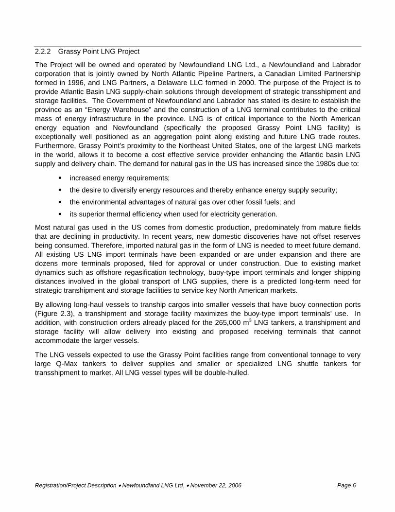
The Project will be owned and operated by Newfoundland LNG Ltd., a Newfoundland and Labrador corporation that is jointly owned by North Atlantic Pipeline Partners, a Canadian Limited Partnership formed in 1996, and LNG Partners, a Delaware LLC formed in 2000. The purpose of the Project is to provide Atlantic Basin LNG supply-chain solutions through development of strategic transshipment and storage facilities. The Government of Newfoundland and Labrador has stated its desire to establish the province as an “Energy Warehouse” and the construction of a LNG terminal contributes to the critical mass of energy infrastructure in the province. LNG is of critical importance to the North American energy equation and Newfoundland (specifically the proposed Grassy Point LNG facility) is exceptionally well positioned as an aggregation point along existing and future LNG trade routes. Furthermore, Grassy Point’s proximity to the Northeast United States, one of the largest LNG markets in the world, allows it to become a cost effective service provider enhancing the Atlantic basin LNG supply and delivery chain. The demand for natural gas in the US has increased since the 1980s due to:
increased energy requirements;
the desire to diversify energy resources and thereby enhance energy supply security;
the environmental advantages of natural gas over other fossil fuels; and
its superior thermal efficiency when used for electricity generation.
Most natural gas used in the US comes from domestic production, predominately from mature fields that are declining in productivity. In recent years, new domestic discoveries have not offset reserves being consumed. Therefore, imported natural gas in the form of LNG is needed to meet future demand. All existing US LNG import terminals have been expanded or are under expansion and there are dozens more terminals proposed, filed for approval or under construction. Due to existing market dynamics such as offshore regasification technology, buoy-type import terminals and longer shipping distances involved in the global transport of LNG supplies, there is a predicted long-term need for strategic transhipment and storage facilities to service key North American markets.
By allowing long-haul vessels to tranship cargos into smaller vessels that have buoy connection ports (Figure 2.3), a transhipment and storage facility maximizes the buoy-type import terminals’ use. In addition, with construction orders already placed for the 265,000 m3 LNG tankers, a transhipment and storage facility will allow delivery into existing and proposed receiving terminals that cannot accommodate the larger vessels.
The LNG vessels expected to use the Grassy Point facilities range from conventional tonnage to very large Q-Max tankers to deliver supplies and smaller or specialized LNG shuttle tankers for transshipment to market. All LNG vessel types will be double-hulled.

Registration/Project Description • Newfoundland LNG Ltd. • November 22, 2006 Page 7
Figure 2.3 LNG Regasification Vessel with Submerged Turret Loading System
2.3 Site Selection
During 2000-2001, North Atlantic Pipeline Partners L.P. assembled a technical team that conducted an initial site selection study to identify potential Newfoundland and Labrador locations for transshipment and storage terminals to supply local requirements and service northeastern US markets. The study was further updated in the Spring of 2005 to include potential Nova Scotia sites. The key requirements for the Project are provided in Table 2.1.
Table 2.1 Key Requirements for LNG Transshipment and Storage Terminal
Tanker sizes to be accommodated Up to 265,000 m3
Tankers per year Up to 400, depending on vessel sizes used.
Number of berths needed Three in total. Two providing for concurrent transshipments, lay-up and temporary storage and one to accommodate STS transfers.
LNG storage volume required at the terminal
Up to 1.3 million m3
Marine/Navigation needs
Unobstructed movement during normal winter ice conditions; minimum 15-m depth throughout shipping channel manoeuvring area and at berth. A wide straight approach to the berth, berth sheltered from prevailing weather conditions; at least two ship lengths turning basin near berth
2.3.1 Key Requirements for the Proposed Terminal
The site selection study involved a systematic review of the region. The requirements for a site to pass the initial screening consisted of the following:
an area free of ice under normal winter conditions;
sufficient water depth to permit safe transit to and from the location by the largest tankers;
an area with harbour potential; that is, a harbour that is generally sheltered from the effects of the prevailing weather conditions; and
an area accessible from the existing road system without major road construction.

Registration/Project Description • Newfoundland LNG Ltd. • November 22, 2006 Page 8
The presence of either icebergs or pack-ice along the north, west and east coasts of Newfoundland eliminated them from further consideration. The extreme east and west ends of the south coast also have unacceptable occurrences of pack ice and/or icebergs and they too were eliminated. The only sub-regions that passed the initial screening process were Fortune Bay, Placentia Bay and St. Mary’s Bay, Newfoundland and Labrador, as well as the Straits of Canso, Nova Scotia.
The locations passing the initial screening were evaluated as potential harbours in the next stage of screening. This involved their assessment with respect to:
marine access (the relative ease or difficulty of navigating an LNG tanker to the proposed jetty location);
harbour potential (shelter, availability of a suitable turning basin immediately adjacent to the jetty);
land access;
land area (the availability of sufficient crown land or municipally owned land for facility development adjacent to the marine facilities); and
land elevation (approximate mean of 10 m but 30 to 40 m above sea level on western shore).
This screening narrowed the potential sites down to seven: Come-by-Chance, Placentia Bay; Admirals Beach, St. Mary’s Bay; Long Harbour, Placentia Bay; Goldboro, Nova Scotia; Point Tupper Flat Head, Nova Scotia; Point Tupper Bear Head, Nova Scotia; and Grassy Point, Placentia Bay.
These seven potential sites were then evaluated with respect to:
marine operations;
physical and biological environment;
regulatory and socio-economic environment; and
cost and schedule.
This evaluation included consideration of the following environmental and socio-economic issues:
historic resources;
commercial fisheries;
geology;
marine mammals;
vegetation,
parks;
fish habitat; and
socio-economics.
2.3.2 Selection of Grassy Point as the Preferred Site
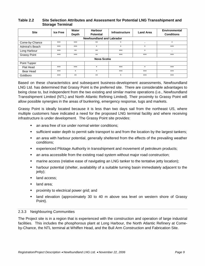
All seven sites rated very closely in the technical evaluation; however, there are notable shortcomings in certain areas. The strengths and weaknesses of each site according to key attributes are highlighted in Table 2.2.
Registration/Project Description • Newfoundland LNG Ltd. • November 22, 2006 Page 9
Table 2.2 Site Selection Attributes and Assessment for Potential LNG Transshipment and Storage Terminal
Site Ice Free Water Depth
Harbour Potential
Infrastructure Land Area Environmental
Conditions Newfoundland and Labrador
Come-by-Chance *** *** ** * - * Admiral’s Beach *** *** * * * *** Long Harbour *** ** ** *** * - Grassy Point *** *** ** *** *** ***
Nova Scotia Point Tupper Flat Head *** *** * *** * *** Bear Head *** * * *** *** *** Goldboro *** ** ** * *** ***
Based on these characteristics and subsequent business-development assessments, Newfoundland LNG Ltd. has determined that Grassy Point is the preferred site. There are considerable advantages to being close to, but independent from the two existing and similar marine operations (i.e., Newfoundland Transshipment Limited (NTL) and North Atlantic Refining Limited). Their proximity to Grassy Point will allow possible synergies in the areas of bunkering, emergency response, tugs and markets.
Grassy Point is ideally located because it is less than two days sail from the northeast US, where multiple customers have indicated a need for the proposed LNG terminal facility and where receiving infrastructure is under development. The Grassy Point site provides:
an area free of ice under normal winter conditions;
sufficient water depth to permit safe transport to and from the location by the largest tankers;
an area with harbour potential, generally sheltered from the effects of the prevailing weather conditions;
experienced Pilotage Authority in transshipment and movement of petroleum products;
an area accessible from the existing road system without major road construction;
marine access (relative ease of navigating an LNG tanker to the tentative jetty location);
harbour potential (shelter, availability of a suitable turning basin immediately adjacent to the jetty);
land access;
land area;
proximity to electrical power grid; and
land elevation (approximately 30 to 40 m above sea level on western shore of Grassy Point).
2.3.3 Neighbouring Communities
The Project site is in a region that is experienced with the construction and operation of large industrial facilities. This includes the phosphorous plant at Long Harbour, the North Atlantic Refinery at Come-by-Chance, the NTL terminal at Whiffen Head, and the Bull Arm Construction and Fabrication Site.

Registration/Project Description • Newfoundland LNG Ltd. • November 22, 2006 Page 10
The 50-km highway distance impact area around the Project site had a population of 8,426 in 2001, the most recent Census year. This is a decrease of more than 2,000 in a decade. The labour force has also decreased by over 500 in the same time period to 3,700 in 2001 (Statistics Canada 1991; 2001). The towns contributing the most to the labour force is Arnold’s Cove (550) and Norman’s Cove-Long Cove (330). As of 2001, 46 percent of the labour force was employed in occupations relating to ‘Trades, Transport and Equipment Operation’ and ‘Occupations Unique to Processing, Manufacturing and Utilities’ (Statistics Canada 2001). Salaries in 2001 averaged $30,348 for men and $14,118 for women. This is higher than the provincial average income for men ($28,144). Women in the area make slightly less than the provincial average ($17,181). The unemployment rate of the area was 25 percent for both men and women in 2001, slightly higher than the provincial averages (Statistics Canada 2001). In 2003, more than 50 percent of the labour force received employment insurance payments as part of their annual income (Community Accounts 2006).
2.3.4 Municipal Planning
On February 27, 1973, an Order in Council (P.O. 1973-480) was passed declaring the Come By Chance waterways a federal port. This port is adjacent to the proposed Newfoundland LNG facility.
The Project Area itself has been the focus of detailed municipal planning exercises over the past fifteen years during which time the whole area was zoned for marine terminal use.
The area from Whiffen Head to Adams Head, which includes the proposed LNG terminal site, was zoned as Rural Use by the Town of Arnold’s Cove in the Arnold’s Cove Municipal Plan and Development Regulations in 1991 and revised in 1992. The area zoning was amended in 1996 to accommodate land use for a marine terminal. The amendment included Hazardous Industry as a Discretionary Use in anticipation of then proposed Newfoundland Transshipment Terminal at Whiffen Head. Examples of Hazardous Industry given in the Development Regulations include “bulk storage of hazardous liquid and substances”. The public was required to be notified and consulted on all amendments to the municipal plan under Provincial legislation. The public was further involved in the review process as the Newfoundland Transshipment Terminal was subject to a Comprehensive Study and associated public consultation under the Canadian Environmental Assessment Act.
The Town of Arnold’s Cove prepared a land use planning map in 1993. This clearly illustrates that Grassy Point was contemplated for use as a marine terminal. The Town boundaries are specified as at the high water mark, however Sec 2 (2) of the Municipalities Act specifies that:
All docks, quays, wharves and structures touching the boundaries of a municipality and all ships attached either permanently or temporarily to a dock, quay, wharf, ship or structure shall be considered to be with and to be part of the municipality.
It is the belief of Newfoundland LNG Ltd. that the proposed LNG Transshipment Terminal is located on lands that have been historically used as a marine terminal and that are designated for such use in a land-use plan that has been the subject of public consultation.

Registration/Project Description • Newfoundland LNG Ltd. • November 22, 2006 Page 11
Figure 2.4 Arnold’s Cove Vision 2020

Registration/Project Description • Newfoundland LNG Ltd. • November 22, 2006 Page 12
3.0 DESCRIPTION OF THE UNDERTAKING
3.1 Geographical Location
The Grassy Point site is located on the eastern shore of northern Placentia Bay, approximately 8 km south of the North Atlantic Refining at Come By Chance and adjacent to NTL at Whiffen Head (Figure 3.1). The Grassy Point land area is bounded by the waters of Placentia Bay to the west and Arnold’s Cove to the east; the approximate location is 47°45.5’ N, 54°01.5’ W. Grassy Point is approximately 2,500 m west of the Public Wharf in Arnold’s Cove. The site is not currently accessible by road. The nearest road is Whiffen Head road, leading to NTL.
The marine approaches to Grassy Point are reasonably sheltered from both winds and waves from all directions, except from the south and southwest. Even for these directions, maximum fetch is limited and complicated by the islands of Placentia Bay so that the development of full ocean swells is not possible. As the site is outside of Come By Chance Bight, tankers could turn easily adjacent to the jetty or further to the northwest, west or southwest. The shipping route along Placentia Bay to the proposed terminal is controlled by an existing vessel traffic system operated by the Canadian Coast Guard (CCG). Suitable navigational aids are already in place along this route.
Figure 3.1 Section of Topographic Map (1:50:000) Showing Grassy Point, Placentia Bay
3.2 Physical Features
Some key features of the Project are:
primary function is to transship and store LNG;
no dredging will be required for construction of the tanker jetty;
minimal dredging will likely be required for construction of the tug basin berths;
no marine or transboundary (offsite) pipelines will be included;
the jetty will provide a maximum of three berths available for up to 265,000 m3 LNG vessels;
eight tanks; each 160,000 m3 single containment structures and dykes;
any onshore pipelines will avoid any onshore waterbodies (i.e., streams); and
no regasification of LNG will occur.

Registration/Project Description • Newfoundland LNG Ltd. • November 22, 2006 Page 13
The primary physical features of the facility are described below in terms of marine (Section 3.2.1) and onshore (Section 3.2.2) components.
3.2.1 Marine Facilities
The marine terminal will consist of a series of three berths. Each berth will be capable of berthing a 265,000 m3 and 140,000 m3 LNG vessel. The construction of the three berths will be phased in over the duration of the Project, but the first two berths may be constructed in close sequence to meet prospective costumer requirements.
Each berth will be similar in construction and will consist of a service platform, mooring dolphins, berthing dolphins, access trestle connecting the loading platform to shore and walkways connecting the mooring and berthing dolphins (Figure 3.2). The service platform will be equipped with fixed loading arms to facilitate loading and unloading of LNG. The on-water foot print of the marine structures will encompass a water lot boundary running southwest approximately 2,250 m from the eastern boundary of the existing NTL water lot boundary. The boundary will then turn southeast and extend approximately 700 m terminating at the southern most point of land at Adams Head.
The berthing structures will be located in approximately 15 m of water such that there is sufficient draught, thereby eliminating the requirement for dredging. In-water blasting is not required.
3.2.1.1 Berths
The three berths will include facilities for the receiving and unloading of LNG cargo from LNG tankers. The piers will have safety design features including quick disconnect loading arms and catch basins.
Each berth will be constructed with the following structures and features:
service platform approximately 30 m x 30 m;
two berthing dolphins approximately 9 m x 12 m;
four mooring dolphins approximately 6 m x 8 m;
steel truss catwalks connecting the dolphin structures;
access trestle capable of carrying vehicle traffic and LNG pipe racks;
quick release mooring hooks;
spill containment equipment;
fire fighting equipment and fire monitors; and
electrical supply and lighting.
Each berth will have four mooring dolphins; two on either side (Figure 3.2). The mooring dolphins are designed to withstand forces created by wind, waves and currents on the LNG tankers. These will accommodate:
triple quick release hook assemblies with powered capstans; and
handrail and bull rails.
Each berth will have two berthing dolphins which are designed to absorb the berthing forces of the LNG tankers. The berthing dolphins will be equipped with energy absorbing fenders.

Registration/Project Description • Newfoundland LNG Ltd. • November 22, 2006 Page 15
3.2.1.2 Sub-structure
The sub-structure support for the service platform, dolphins and access trestle will be steel-pipe-piles which are driven into the bedrock and grouted to the pile caps. An optional structural configuration would use pre-fabricated steel jackets. Both of these systems are currently in use at the Newfoundland Transshipment facility. The final selection of the structural system will be determined upon completion of the geotechnical surveys, engineering design and costing exercises.
All piling will consist of steel pipes which are driven/drilled into the bedrock. Piles under tension loads will have to be fixed to the seabed by grouting anchors into the pile annulus and drilling and grouting the anchors into the bedrock. All drill cuttings will be returned to the drilling barge and discharged onshore in accordance with regulatory requirements.
3.2.1.3 Superstructure
The superstructure of each of the marine structures will consist of a combination of pre-cast concrete elements combined with in-situ concrete. Concrete bases will be provided for mechanical equipment. Handrails and bull rails will provide protection along the perimeter of the service platform, mooring dolphins and berthing dolphins.
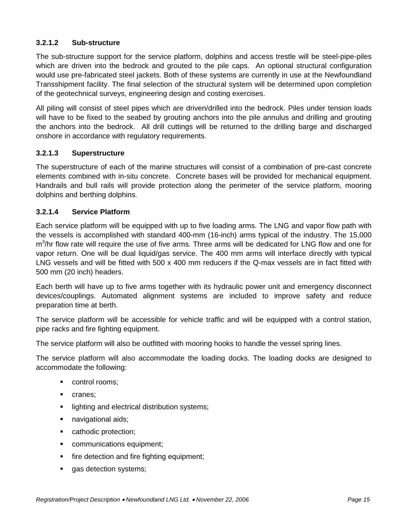
3.2.1.4 Service Platform
Each service platform will be equipped with up to five loading arms. The LNG and vapor flow path with the vessels is accomplished with standard 400-mm (16-inch) arms typical of the industry. The 15,000 m3/hr flow rate will require the use of five arms. Three arms will be dedicated for LNG flow and one for vapor return. One will be dual liquid/gas service. The 400 mm arms will interface directly with typical LNG vessels and will be fitted with 500 x 400 mm reducers if the Q-max vessels are in fact fitted with 500 mm (20 inch) headers.
Each berth will have up to five arms together with its hydraulic power unit and emergency disconnect devices/couplings. Automated alignment systems are included to improve safety and reduce preparation time at berth.
The service platform will be accessible for vehicle traffic and will be equipped with a control station, pipe racks and fire fighting equipment.
The service platform will also be outfitted with mooring hooks to handle the vessel spring lines.
The service platform will also accommodate the loading docks. The loading docks are designed to accommodate the following:
control rooms;
cranes;
lighting and electrical distribution systems;
navigational aids;
cathodic protection;
communications equipment;
fire detection and fire fighting equipment;
gas detection systems;

Registration/Project Description • Newfoundland LNG Ltd. • November 22, 2006 Page 16
gangways;
dry chemical storage;
LNG offloading arms;
vapour loading arms; and
hydraulic power units with accumulators.
3.2.1.5 Access Trestles
An access trestle will serve to provide a support system for the pipe racks, mechanical systems, electrical trays and vehicle traffic. The trestle lengths will vary with each berth. The overall width will be sufficient to provide one way vehicle traffic, pedestrian right-of-way (RoW), pipeline and other utilities.
Trestles will be constructed of steel plate girders with pre-cast deck elements. Piping and utilities will be supported by a steel truss structure. The trestle will be supported on a concrete pile cap supported on steel pipe piles. Elastomeric bearing pads will be provided under each of the trestle bearing points.
3.2.1.6 Access Walkways
Steel truss walkways will link the service platform, berthing dolphins and mooring dolphins. The walkways will also carry the cable trays for electrical conduits for power and navigation aids.
3.2.1.7 Tug Basin
The tug basin will require a minimum of 7 m water depth and be capable of berthing two to three tugs. Dredging may be required for the tug basin, but the material will be disposed of on land. The material used to construct the tug basin will be washed rock from a nearby quarry. The particular size of each material is as follows:
shoreline granular fill: 1 to 250 kg;
rock sub-mattress: 1 to 250 kg;
rock mattress: 20 to 75 mm;
filter stone: 100 to 1200 kg;
scour Protection: 500 to 2,000 kg;
armour stone: 2 to 6 t.
The preliminary footprint of the infill area for the tug basin will be approximately 23,000 m2. However, with detailed engineering, the footprint may change by as much as 50 percent. In any case, about 33 percent of the footprint of the tug basin infrastructure will be replaced by the vertical boulder habitat created by armour stone and fill material below mean low tide. The detail for the tug basin construction is illustrated in Figure 3.3.


Registration/Project Description • Newfoundland LNG Ltd. • November 22, 2006 Page 18
3.2.2 Onshore Component
The primary code requirements for the design and layout of the LNG storage tanks is Canadian Standards Association (CSA) Z276-01 Liquefied Natural Gas (LNG) – Production, Storage, and Handling, which has just been updated to include more conservative computer-based risk modeling requirements. Also important is the US National Fire Protection Agency Code (NFPA 59A) that is used to define the fire safety and prevention aspects of the facility design. The key portions of the code that affect tank spacing and hence land usage are the thermal radiance and vapour cloud dispersion requirements.
The dominant factor in the overall layout of the land-based portion of the facility is the location of the LNG storage tanks. Standards and codes define the allowable spacing between tanks and the allowable proximity of other facility structures and equipment as well as the allowable impact (in the unlikely event of an accidental release or fire) upon neighboring lands that may be occupied and with no access control by the terminal owner. A key factor in this spacing determination is the size and design of the individual LNG tanks.
The facility will be designed for LNG ship-to-ship transfers, storage and reloading onto LNG tankers for transshipment to market destinations. The Project will consist of a tank farm of eight storage tanks, interconnecting flow lines, reliquefaction equipment, vapourization and power generation, support facilities, a waste water handling system and a fire protection system. LNG pipe specifications, routing, size and configuration will be determined during the Engineering and Design stage of the Project. Treatment facilities for ballast water will not be required as the tankers will have segregated ballast that will not contain hydrocarbons. Monitoring of these segregated ballast systems will be part of preventative ship maintenance, which is one of the standards for vetting second-leg tankers for use at the transshipment terminal. The facilities will include onshore and jetty fire fighting capability and on-site spill containment and clean-up equipment.
3.2.2.1 LNG Storage Tanks
Ultimately, the total number of tanks at the site will be eight, providing up to 1.3 million m3 of LNG storage. The LNG storage tanks incorporated into the design basis for all stages are 160,000 m3 gross capacity and of single containment design. This size was selected for compatibility with the majority of the LNG vessel fleet in operation and in design/build. They are currently being built by multiple vendors. The single containment design is the most conservative in terms of meeting standards and design codes, since it will require the most fire safety and the widest spacing from other structures and from the property line. The use of double or full containment designs will fall well within these parameters, most notably is the layout spacing.
Tanks may be of steel or concrete construction. These tank types are defined in European Standard EN 1473 (1997), and are described below. Design specifications and standards are provided in CSAZ276. A single containment tank is defined in EN 1473 as:
A single primary container and generally an outer shell designed and constructed so that only the primary container is required to meet the low temperature ductility requirements for storage of the product. The outer shell of a single containment storage tank is primarily for the retention of insulation and to contain the purge gas (product vapour) pressure, but is not designed to contain refrigerated liquid in the event of leakage from the primary container.

Registration/Project Description • Newfoundland LNG Ltd. • November 22, 2006 Page 19
Single containment tanks are the most common in the Americas. They normally consist of a stainless steel (9 percent nickel in steel) inner tank and a carbon steel or reinforced concrete outer tank. The tank is surrounded by a dyke impoundment sized to accommodate 100 percent of the tank’s volume. Due to the large area of the impoundment, the thermal exclusion zone distances for single containment tanks are large.
Each tank will be capable of handling 15,000 m3/hr flow rates in and out and will generate a BOG volume of 0.05 percent of its volume daily (80 m3/day = 3.3 m3/hr liquid = 1,980 m3 of natural gas). The normal operating pressure of the tanks will be 2.0 psi. Each tank will be equipped with three submerged pumps capable of delivering a combined 15,000 m3/hr. BOG not used for power generation will be sent to the reliquefaction system that will return the volume back to the tank.
The tanks will be field erected on foundations designed to preclude thermal frost heave either with the design of an air-gap foundation or use of a heated pad. The materials will be brought to the site via the construction dock in pre-assembled pieces as large as can be accommodated by barge and the site.
3.2.2.2 Surge Tanks and Peak Shaving Storage
Two vacuum-insulated LNG surge tanks will be installed, one for the output of the LNG reliquefaction systems and one for the suction of the LNG booster pump. The vacuum insulation creates a “thermos bottle” type of protection against heat gain, resulting in virtually no contribution to the overall process system heat gain. These tanks will be brought to site from the fabricators shop as a complete unit.
3.2.3 Site Plan
The site plan for the full build-out (eight tanks and three piers) of the Project is presented in Figure 3.4.
3.3 Environmental Setting
Baseline studies to support the environmental assessment of the Project have been conducted for:
Marine Fish Habitat;
Freshwater Fish and Fish Habitat;
Vegetation and Rare Plants;
Waterfowl; and
Historic Resources.
The results of each survey are presented below in relevant sections. Each survey was conducted within the Study Area defined as the area south of the NTL property boundary, south to Bordeaux Cove. Baseline socio-economic and commercial fisheries surveys are ongoing.

Registration/Project Description • Newfoundland LNG Ltd. • November 22, 2006 Page 21
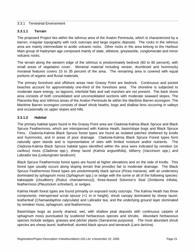
3.3.1 Terrestrial Environment
3.3.1.1 Terrain
The proposed Project lies within the isthmus area of the Avalon Peninsula, which is characterized by a barren, irregular topography with rock outcrops and large organic deposits. The rocks in the isthmus area are mainly intermediate to acidic volcanic rocks. Other rocks in the area belong to the Harbour Main group of Hadrynian age composed mainly of slate, siltstone, greywackle, conglomerate and minor volcanic rocks.
The terrain along the western edge of the isthmus is predominately bedrock (60 to 80 percent), with small areas of vegetation cover. Morainal material including veneer, drumlinoid and hummocky morainal features covers 15 to 35 percent of the area. The remaining area is covered with equal portions of organic and fluvial materials.
The primary foreshore and offshore areas near Grassy Point are bedrock. Continuous and pocket beaches account for approximately one-third of the foreshore area. The shoreline is subjected to moderate wave energy, so lagoons, intertidal flats and salt marshes are not present. The back shore area consists of both consolidated and unconsolidated sections with moderate seaward slopes. The Placentia Bay and Isthmus areas of the Avalon Peninsula lie within the Maritime Barren ecoregion. The Maritime Barren ecoregion consists of dwarf shrub heaths, bogs and shallow fens occurring in valleys and occasionally on upper slopes and hills.
3.3.1.2 Habitat
The primary habitat types found in the Grassy Point area are Cladonia-Kalmia Black Spruce and Black Spruce Feathermoss, which are interspersed with Kalmia Heath, basin/slope bogs and Black Spruce Fens. Cladonia-Kalmia Black Spruce forest types are found as isolated patches sheltered by knolls and hummocks, and in areas of poor drainage. Cladonia-Kalmia Black Spruce Forest types form naturally open stands and is representative of sites with limited moisture and/or nutrients. The Cladonia-Kalmia Black Spruce habitat types identified within the area were indicated by reindeer (or caribou) moss (Cladonia spp.), sheep laurel (Kalmia angustifolia), bilberry (Vaccinium spp.) and Labrador tea (Ledumgroen landicum).
Black Spruce Feathermoss forest types are found at higher elevations and on the side of knolls. This forest type usually occurs along sloping terrain that provides fair to moderate drainage. The Black Spruce Feathermoss forest types are predominantly black spruce (Picea mariana), with an understory dominated by sphagnum moss (Sphagnum spp.) or sedge with the some or all of the following species: bakeapple (cloudberry (Rubus chamaemorus)), three-leaved Solomon’s Seal (Smilacina trifolia), feathermoss (Pleuzorium schreberi), or sedges.
Kalmia Heath forest types are found primarily on exposed rocky outcrops. The Kalmia Heath has three components: interspersed scrub spruce (<1 m in height), shrub canopy dominated by sheep laurel, leatherleaf (Chamaedaphne calyculata) and Labrador tea; and the underlying ground layer dominated by reindeer moss, sphagnum, and feathermoss.
Basin/slope bogs as poorly drained, wet, with shallow peat deposits with continuous carpets of sphagnum moss punctuated by scattered herbaceous species and shrubs. Abundant herbaceous species include sedges, grasses and pitcher plants (Sarracenia purpurea). The most abundant shrub species are sheep laurel, leatherleaf, stunted black spruce and tamarack (Larix laricina).

Registration/Project Description • Newfoundland LNG Ltd. • November 22, 2006 Page 22
Black Spruce Fens forest types are present along stream and drainage gullies, and in areas where there is low to moderate drainage. They open black spruce forests with a lush understorey of sedges, ferns and forbs. Black Spruce Fens are characterized by some or all of the following species: bottle brush (Callistemon spp.), purple stemmed aster (Symphyotrichum puniceum), bakeapple, purple avens (Geum rivale), broad-lipped twayblade (Listera convallarioides), naked miterwort (Mitella nuda) and/or wild sarsaparilla (Aralia nudicaulus) forbs.
Vegetation within 1 m around the perimeter of the water bodies surveyed is listed in Table 3.1. Sphagnum moss, grasses sedges and rushes dominated the perimeter of most water bodies. The remaining species accounted for less than five percent of the ground cover around each water body.
Table 3.1 Vegetation Surrounding Water Bodies
Common Name Scientific Name Black Crowberry Empetrum nigrum Sheep Laurel Kalmia angustifolia Caribou Moss spp. Cladonia rangiferina, Cladonia alpestris, Cladonia alpestris, Cladonia mitis Sphagnum spp. Sphagnum spp. Grasses, Sedges, and Rushes Poaceae spp., Carex spp., and Juncus spp. Leatherleaf Chamaedaphne calyculata Low Sweet Blueberry Vaccinium angustifolium Common Juniper Juniperus communis Yellow Pond Lily Nuphar veriegatum Bakeapple Rubus chamaemorus Black Spruce Picea mariana Aster spp. Aster spp. Eastern Larch (tamarack) Larix laricina Chuckley-pear spp. Amelanchier spp. Sweetgale Myrica gale Pitcher-plant Sarracenia purpurea
3.3.1.3 Vegetation Community and Rare Plant Surveys
Methods
Prior to the commencement of field studies a search was conducted of the Atlantic Canada Conservation Data Centre (ACCDC) database for any known occurrences of rare plant species within the Study Area.
Aerial photos of the area were reviewed to assist in the identification of distinct vegetation community boundaries and to identify any habitats with a high potential for rare plant occurrence. High potential habitats for rare plant species include such areas as rich wetlands, unique geology rock outcrops and riparian zones and habitats specific to rare plants known to occur in the area.
General vegetation community surveys were conducted simultaneously with a rare plant survey of the Study Area. General vegetation community plots were completed in representative areas as identified during the aerial photo review and during the ground assessment. Plot information included a listing of dominant plant species, estimate of percent cover, slope position, moisture and nutrient regime, a general habitat description and representative photographs. A hand-held Global Positioning System (GPS) receiver was used to record the location for each plot.
Rare plant plots were surveyed in the high potential habitat areas identified during the aerial photo review as well as those identified during the ground assessment. Rare plant plot information included a listing of all vascular plant species observed at each site, a general habitat description, GPS recorded

Registration/Project Description • Newfoundland LNG Ltd. • November 22, 2006 Page 23
location and representative photographs. Plant species that were not readily identifiable in the field were collected for identification later.
For potential boreal felt lichen (Erioderma pedicellatum) (BFL) habitat includes mature and senescent balsam fir (Abies balsamea) forests. These habitat types were identified during the aerial photograph review. Balsam fir forests within the Study Area were targeted for BFL ground surveys. The coordinates for the proposed access road were loaded into the GPS with the use of Geographic Information System (GIS) to ensure the route was sufficiently surveyed.
Field surveys for BFL were conducted in pre-selected habitat areas as well as on an opportunistic basis. In addition to the visual assessment for the presence of BFL, the presence or absence of indicator species (Coccocarpia sp., Lichenoides sp. and Frullania tamarisci ssp. asagrayana) were also noted. Survey locations were recorded with the use of the hand-held GPS receiver. Photographs were taken of any potential BFL thalli and the tree was marked with flagging tape.
Results
The Study Area is dominated by balsam fir forests, tuckamor, sphagnum bog and complexes of tuckamor and sphagnum bog. Nutrient rich wetlands were limited to very small riparian sedge fens. A total of 46 vascular plant species were observed within the study area with none of them considered rare or uncommon.
The RoW for much of the road access route was cut through the balsam fir forest stands. As a result, surveys for BFL along the route were conducted in stands parallel to the route within 50 m of the cut RoW. A total of five BFL survey sites were established that included one transect. Where appropriate (e.g., balsam fir forest sites), BFL surveys were also conducted in conjunction with the general vegetation surveys on an ad hoc basis.
The only BFL indicator species observed within the Study Area was Frullania tamarisci. BFL was not observed in any surveyed site. At several sites, arboreal lichen species were found to be in an apparent state of necrosis. Photographs of several examples were taken along with the location coordinates.
3.3.1.4 Wildlife
Several wildlife species potentially occur in the area of Grassy Point: moose (Alces alces), coyote (Canis latrans), red fox (Vulpes vulpes), lynx (Lynx canadensis), northern river otter (Lutra canadensis), mink (Mustela vison ), beaver (Castor canadensis), muskrat (Ondatra zibethicus), meadow vole (Microtus pennsylvanicus), snowshoe hare (Lepus americanus), ermine (Mustela erminea), red squirrel (Tamiasciurus hudsonicus), masked shrew (Sorex cinereus) and little brown bat (Myotis lucifugus). During the field programs for freshwater fish and waterfowl, evidence was found of otter, muskrat, moose, squirrel, and hare within the Study Area. The relative small land area of Grassy Point peninsula and its limited access likely restricts terrestrial animal density.

Registration/Project Description • Newfoundland LNG Ltd. • November 22, 2006 Page 24
3.3.2 Marine Environment
3.3.2.1 Physical Oceanography
Placentia Bay is a major embayment of the south coast of Newfoundland, bounded on the west by the Burin Peninsula and on the east by the Avalon Peninsula. The axis of the bay lies in a northeasterly orientation, with its opening to the Atlantic Ocean at the southwest. The opening at the mouth of the bay is approximately 87 km wide, with a depth at the middle of approximately 240 m. Placentia Bay contains numerous islands and shoals. The eastern half of the bay is characterized by a well-defined channel, Eastern Channel, with depths of typically 200 m, which run from the mouth almost to the head of the bay. The western half of Placentia Bay is characterized by numerous banks, shoals and reefs. The bay contains several islands, the largest being Merasheen Island, Long Island and Red Island. Because of the orientation of its mouth, Placentia Bay is exposed to winds, waves and currents from the Atlantic Ocean.
Waves at Grassy Point will likely be less than 1 m for more than 90 percent of the time. Near-calm conditions may be expected approximately 40 percent of the time. Waves are not expected to exceed 0.5 m more than 25 percent of the time from May to September. Larger waves up to 2.5 m may propagate into the area from the southwest. The 10-year and 100-year return period significant wave heights are 3.0 and 3.5 m, respectively. The mean tide range at Grassy Point is 1.62 m. The large tide range is 2.47 m.
Currents in Come By Chance Harbour are weak and variable, with speeds in the range of 5 to 30 cm/s. A maximum speed of 50 cm/s has been measured on one occasion outside the mouth of the shipping lane approaches to Come By Chance. The general surface circulation pattern in Placentia Bay is counter-clockwise, with an inward flow along the eastern shore and southwesterly flow out the western shore.
Locally-formed landfast ice of only a few centimetres thickness may occur at the head of Placentia Bay in mid to late March for a period unlikely to exceed one week. The occurrence of sea ice is an occasional event in Placentia Bay.
Icebergs are extremely unlikely to drift to the head of Placentia Bay. Icebergs have been sighted in the Eastern Channel and near Argentia but are more likely to appear near the mouth of the Bay, approximately 68 nautical miles (126 km) to the south.
3.3.2.2 Fish and Fish Habitat
The intertidal habitat along the western shore of the Grassy Point peninsula is rocky and moderately exposed. The shoreline alternates between bedrock/boulder headlands and gravel/cobble pocket beaches (Figure 3.5). The headlands extend into the water several metres and are covered primarily with Fucus and filamentous red algae. The intertidal zone near the pocket beaches is relatively void of vegetations, apart from occasional smooth cord weed (Chorda filum). Characteristic fauna of these rocky shallow subtidal habitats are periwinkles (Littorina spp.), barnacles (Balanus spp.), sea urchins (Strongylocentrotus droebachiensis), horse mussels (Modiolus modiolus) and blue mussels (Mytilus edulis).

Registration/Project Description • Newfoundland LNG Ltd. • November 22, 2006 Page 25
Figure 3.5 Shoreline from Grassy Point Looking North
A marine habitat survey was conducted on September 18 and 19, 2006, by recording video transects within the proposed marine footprint of the Project. SCUBA divers recorded video along predetermined transects corresponding to the tug basin and footprint of the tug basin causeway and terminal infrastructure. The video was later reviewed by a marine biologist to describe the species present and to produce a habitat map (Figure 3.6).
Generally, the intertidal and shallow subtidal habitat nearshore reflects the shoreline substrate. Seaward of the headlands, the substrate is composed of bedrock outcrop and boulders. Algal species present on these outcrops include Irish moss (Chondrus crispus), tubed weeds (Polysiphonia spp.), banded weeds (Ceramium spp.), coral weed (Corallina officinalis), cord weed, edible kelp (Alaria esculenta) and rockweed (Fucus vesiculosus). Dominant faunal species off these headlands are the common periwinkle (Littorina littorea), frilled anemone (Metridium senile), mussels, sea urchins and cunner (Tautogolabrus adspersus).
Seaward of the pocket beaches, the substrate in the shallow intertidal is a mix of cobble and small boulder with little vegetation, apart from occasional cord weed. Fauna was dominated by sea stars (Asterias vulgaris) and sea urchins.

0.6
-27.1
-4.0-6.4
-22.3
-6.1
-13.4
-8.5
-34.0
-28.3-17.7
-19.5
-27.0 -6.4
-2.7
-33.0
-24.4
-30.0
-20.0
-10.0
-5.0
-15.0
10
10
1020
20
20
20
30
20
-2.0D2
D3
D4
J3B
J3A
J1B
J1A
TB3
TB4
J2AJ2B
TB2
TB1 0 50 100 150 20025Metres
CLIENT:
PROJECT TITLE:
DRAWING TITLE:
SCALE:
DRAWN BY:
EDITED BY:
DRAWING No.:
MAP FILE:
NEWFOUNDLAND LNG LIMITED
REGISTRATION/PROJECT DESCRIPTION
HABITAT TYPES WITHIN FOOTPRINT OF TERMINAL AND TUG BASIN
1:3250
SAR
LL
FIGURE 3.61015846_05.MXD
DATE:
CHECKED BY:
REV. No.
NOV. 08, 2006
0
NOTES:1. DO NOT SCALE FROM DRAWING.2. © JACQUES WHITFORD, 2006.3. WATER DEPTH IN METRES.
06/11/2006
LEGENDSediment Transects
Sand/GravelGravel/CobbleCobble/BoulderBedrockBoulder/Bedrock
Coralline Algae DominantSand/GravelGravel/CobbleCobble/Boulder

Registration/Project Description • Newfoundland LNG Ltd. • November 22, 2006 Page 27
Beyond the shallow subtidal, substrates are intermittent between sand/gravel, gravel/cobble or cobble/boulder (Figure 3.6). Coralline algae (Lithothamnium spp.) is a dominant substrate feature in several areas surveyed.
In particular, the subtidal area of the proposed tug basin is a mix of boulder/bedrock from the headlands to approximately 2 to 3 m water depth, then cobble/boulder to 5 m deep. This area is generally a mix of sand and gravel from 5 to 10 m deep and a composite of cobble and boulder between 10 and 15 m water depth.
Within the boulder/cobble substrate at 10 to 15 m water depth, there were occasional patches of coralline algae and sand. Sea urchins occurred in clumps, sea anemones were abundant on boulders and cunners, brittle stars (Ophiopholis aculeata) and rock crab (Cancer irroratus) occurred near boulders. Within the sand/gravel substrate there were occasional sea stars, scallops and empty mussel and urchin shells. A rock gunnel (Pholis gunnellus), rock crab and a hermit crab (Pagurus spp.) were also observed using this sand/gravel habitat.
Within the shallow subtidal boulder/bedrock nearshore, there was an abundance of filamentous bushy red seaweeds (e.g., Polysiphonia, Ceramium), coral weed (Corallina officinalis), Irish moss, Fucus and periwinkles (Figure 3.7). The faded Irish moss is typical after a summer of warm water temperatures and nitrogen depletion. We also saw the effects of high water temperatures and low nutrient levels in Alaria leaf break down.
Figure 3.7 Boulder/Bedrock Algal Community Nearshore

Registration/Project Description • Newfoundland LNG Ltd. • November 22, 2006 Page 28
North of the tug basin, Jetty 2 extends from approximately the 15 m contour, shoreward to Grassy Point. Between the 20 and 10 m contours, the substrate is a mix of sand/gravel and occasional boulders, with occasional coralline algae, sea urchins and sea stars. One scallop and one winter flounder (Pseudopleuronectes americanus) were observed along this section. At approximately the 10 m contour, the coralline alga becomes denser, with horse mussels imbedded within (Figure 3.8). There are also patches of sand and gravel and occasional boulder. Closer to shore at Grassy Point, there is a patch of boulders where cunners are abundant. There are urchins, anemones and some filamentous red algae on the rocks, but little other vegetation apart from an occasional piece of smooth cord weed.
Figure 3.8 Typical Substrate in the Area of Jetty 2
Jetty 1 is planned to extend out to near the 20 m contour. Between 20 and 15 m depths, the substrate is predominately cobble-sized coralline algae. There are occasional mussels, urchins, sea stars and scallop. Cunners are common near boulder patches. Between the 15 and 2 m contours, approximately, the substrate is a mixture of sand and gravel (Figure 3.9). Here, there were occasional patches of urchins, sea stars and mussels. Rock crab and a winter flounder were also observed. Closer to shore, in this sand and gravel substrate, smooth cord weed begins to appear and becomes more abundant in the shallow subtidal rocky area off the headland. These boulders are covered in filamentous red algae, with occasional anemones and urchins attached. Cunners are abundant. Alaria occurs in the shallow subtidal and intertidal zones.

Registration/Project Description • Newfoundland LNG Ltd. • November 22, 2006 Page 29
Figure 3.9 Typical Substrate in the Area of Jetty 1
Jetty 3 is the longest of the three and extends from near the 20 m contour to the shoreline (Figure 3.10). The footprint of Jetty 3 at the deepest section is a mix of cobble and boulder, with filamentous red algae and coralline algae covering portions of some rocks. Anemones and urchins are common, while Agarum and sea stars occur infrequently. Cunners were abundant in this area at the time of the survey. Moving shoreward, the boulders become larger and there is an occasional bedrock outcrop over the next 25 m, approximately. Coralline algae occurs in dense pockets, mussels, sea stars and urchins are more frequent and cunners become scarce and scallop occasionally occur. A thorny skate (Raja radiata) and winter flounder were also observed along this transect. The sand/gravel section of the Jetty 3 footprint was relatively barren of flora and fauna; however, sea stars and empty mussel and urchin shells occasionally occurred. As with all other transects, the boulder/bedrock habitat nearshore was covered in filamentous red alga and smooth cord weed and cunners were abundant. Irish moss and Alaria also occurred on the rocks nearshore. The substrate near the adjacent pocket beach was composed of gravel and cobble with patches of smooth cord weed, Alaria and Irish moss.

Registration/Project Description • Newfoundland LNG Ltd. • November 22, 2006 Page 30
Figure 3.10 Typical Substrate in the Area of Jetty 3
The potential footprint of the service platforms, mooring dolphins and berthing dolphins was also surveyed, except for depths beyond 20 m, which were not surveyed due to safe diving limit restrictions. These structures will be placed at water depths ranging beyond 20 m to approximately 10 m. The substrate in this area ranges from bedrock outcrop to patches of sand and gravel. From the head of Jetty 3 (J3B), southward to D2, the substrate alternates between bedrock outcrop and cobble/boulder, with small pockets of coralline algae and sand. Urchins, anemones, sea stars and filamentous red algae occasionally occur. Cunners were present in low numbers, as were mussels. Coralline algae becomes the dominant substrate feature near waypoint D2, and apart from a small exposed bedrock outcrop, continues to be prominent for the next approximately 270 m. Coralline algae pockets or boulders occur over the surface of bedrock in some areas. Cunners were present wherever there was a relief of boulders (Figure 3.11). Benthic macrofauna were limited to urchins, mussel shells and sea stars. One ocean pout (Macrozoarces americanus) was also observed in this section. In the sand/gravel section of substrate south of J1B, there were occasional scallop and one thorny skate. South of D3, cobble/boulder substrate is prominent, with occasional pockets of coralline algae or sand/gravel. Species observed over this substrate were urchins, filamentous red algae, anemones, mussels and Agarum. On the bedrock outcrop, mussels and coralline algae were common. A portion of the outcrop was covered by cobble and boulder, so the definition of the outcrop in Figure 3.6 is uncertain.
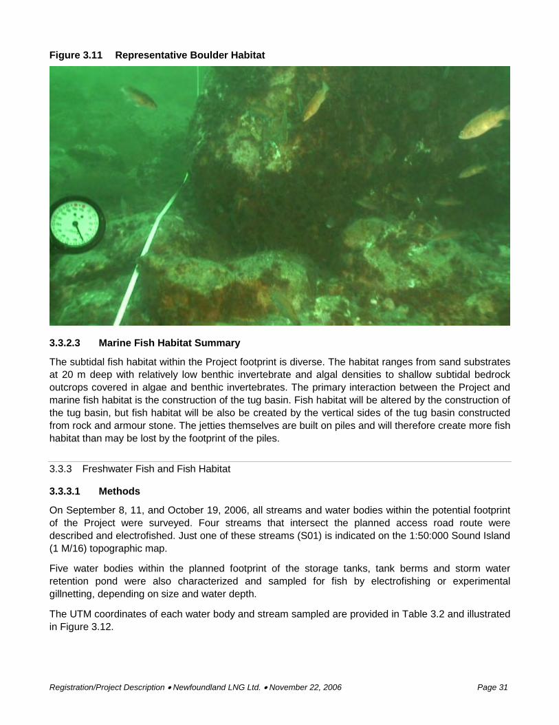
Registration/Project Description • Newfoundland LNG Ltd. • November 22, 2006 Page 31
Figure 3.11 Representative Boulder Habitat
3.3.2.3 Marine Fish Habitat Summary
The subtidal fish habitat within the Project footprint is diverse. The habitat ranges from sand substrates at 20 m deep with relatively low benthic invertebrate and algal densities to shallow subtidal bedrock outcrops covered in algae and benthic invertebrates. The primary interaction between the Project and marine fish habitat is the construction of the tug basin. Fish habitat will be altered by the construction of the tug basin, but fish habitat will be also be created by the vertical sides of the tug basin constructed from rock and armour stone. The jetties themselves are built on piles and will therefore create more fish habitat than may be lost by the footprint of the piles.
3.3.3 Freshwater Fish and Fish Habitat
3.3.3.1 Methods
On September 8, 11, and October 19, 2006, all streams and water bodies within the potential footprint of the Project were surveyed. Four streams that intersect the planned access road route were described and electrofished. Just one of these streams (S01) is indicated on the 1:50:000 Sound Island (1 M/16) topographic map.
Five water bodies within the planned footprint of the storage tanks, tank berms and storm water retention pond were also characterized and sampled for fish by electrofishing or experimental gillnetting, depending on size and water depth.
The UTM coordinates of each water body and stream sampled are provided in Table 3.2 and illustrated in Figure 3.12.