en_tapcon 230 expert manual instruþ§es de operaþÒo
TRANSCRIPT

Voltage Regulator TAPCON® 230
Operating Instructions 2136339www.reinhausen.com

© 2009 A
Unauthotents are
Offenderof a pate
The prod
We expre
The infororders a
The orig
ll rights reserved, Maschinenfabrik Reinhausen
rised copying and distribution of this document and the utilisation and communication of its con- strictly prohibited unless expressly authorised.
s will be held liable for the payment of damages. All rights reserved in the case of registration nt, utility model or registered design.
uct may have been modified after this document went to press.
ssly reserve the right to make changes to the technical data, the design or the scope of delivery.
mation provided and the arrangements agreed during processing of the relevant quotations and re strictly binding.
inal operating instructions were drawn up in German.
Table of Contents
Table of Contents
1 Introduction..................................................................................11
1.1 Manufacturer........................................................................................... 11
1.2 Subject to change without notice ............................................................ 11
1.3 Completeness ......................................................................................... 11
1.4 Supporting documents ............................................................................ 12
1.5 Safekeeping ............................................................................................ 12
1.6 Notation conventions .............................................................................. 12
1.6.1 Abbreviations used ............................................................................................. 13
1.6.2 Hazard communication system .......................................................................... 15
1.6.3 Information system ............................................................................................. 16
1.6.4 Instruction system............................................................................................... 16
1.6.5 Typographic conventions.................................................................................... 17
2 Safety........................................................................................... 19
2.1 General safety information...................................................................... 19
2.2 Appropriate use....................................................................................... 19
2.3 Inappropriate use .................................................................................... 19
2.4 Personnel qualification............................................................................ 20
2.5 Operator duty of care .............................................................................. 20
3 Product description.................................................................... 23
3.1 Description of functions........................................................................... 23
3.2 Features TAPCON® 230.......................................................................... 25
3.3 TAPCON® 230 pro................................................................................... 25
3.4 TAPCON® 230 expert .............................................................................. 26
© Maschinenfabrik Reinhausen 2009 2136339/01 EN TAPCON® 230 3

Table of Contents
3.5 Scope of delivery .................................................................................... 27
3.6 Hardware description.............................................................................. 27
3.7 Description of the front panel.................................................................. 31
3.8 Description of the display ....................................................................... 32
3.9 Description of key functions.................................................................... 33
3.10 TAPCON® 230 operating safety .............................................................. 35
4 Packaging, transport and storage............................................. 37
4.1 Packaging............................................................................................... 37
4.1.1 Purpose .............................................................................................................. 37
4.1.2 Suitability, structure and material........................................................................ 37
4.1.3 Labelling ............................................................................................................. 37
4.2 Transport, reception and handling of shipments..................................... 38
4.3 Storage of shipments.............................................................................. 39
5 Functions and Settings .............................................................. 41
5.1 NORMset................................................................................................ 42
5.1.1 Activating NORMset ........................................................................................... 43
5.1.2 Deactivating NORMset....................................................................................... 44
5.2 Control parameters................................................................................. 48
5.2.1 Voltage regulation............................................................................................... 48
5.2.2 Limit values ........................................................................................................ 60
5.2.3 Compensation .................................................................................................... 70
5.3 Configuration .......................................................................................... 78
5.3.1 Transformer data ................................................................................................ 78
5.3.2 General............................................................................................................... 87
5.4 Parallel control........................................................................................ 99
5.4.1 Activate Parallel Operation............................................................................... 100
5.4.2 Disabling parallel operation .............................................................................. 100
TAPCON® 230 2136339/01 EN © Maschinenfabrik Reinhausen 20094
Table of Contents
5.4.3 Parallel operation method................................................................................. 101
5.4.4 Assigning paralleling group .............................................................................. 106
5.4.5 Entering the CAN Address ............................................................................... 107
5.4.6 Activating/deactivating stand-alone blocking.................................................... 107
5.4.7 Setting circulating reactive current sensitivity................................................... 108
5.4.8 Setting the blocking threshold for the maximum permitted circulating reactive current .............................................................................................................. 109
5.4.9 Activating/deactivating master/follower current blocking .................................. 110
5.4.10 Setting the delay time for the parallel operation error message ........................111
5.4.11 Selecting the follower tapping direction ............................................................ 112
5.4.12 Setting the maximum tap difference ................................................................. 113
5.4.13 Activating/deactivating follower tapping without measuring voltage................. 114
5.5 Assigning freely configurable inputs/outputs......................................... 115
5.5.1 Assigning inputs (GPIs) .................................................................................... 116
5.5.2 Assigning outputs (GPOs) ................................................................................ 118
5.5.3 Setting LEDs..................................................................................................... 120
5.6 Tap position capture.............................................................................. 123
5.6.1 Tap position input options ................................................................................. 124
5.6.2 Assigning the analog value for the minimum tap position ................................ 125
5.6.3 Setting the analog value for the maximum tap position.................................... 126
5.6.4 Setting the lowest tap position.......................................................................... 127
5.6.5 Setting the highest tap position ........................................................................ 128
5.6.6 Setting the lower tap position blocking limit...................................................... 129
5.6.7 Setting the upper tap position blocking limit ..................................................... 130
5.6.8 Setting the tap position blocking mode............................................................. 131
5.7 Remote setting of voltage level............................................................. 132
5.7.1 Remote voltage level setting options................................................................ 133
5.7.2 Setting the analog value for the minimum voltage level ................................... 134
5.7.3 Setting the analog value for the maximum voltage level .................................. 135
5.7.4 Setting the minimum voltage level.................................................................... 136
5.7.5 Setting the maximum voltage level................................................................... 137
5.8 Communication interface (only TAPCON® 230 expert) ......................... 138
5.8.1 Selecting the communication protocol.............................................................. 139
5.8.2 Selecting the communication port .................................................................... 140
5.8.3 Selecting the communication baud rate ........................................................... 141
5.8.4 Obtaining the network address......................................................................... 142
5.8.5 Assigning the TCP port..................................................................................... 143
© Maschinenfabrik Reinhausen 2009 2136339/01 EN TAPCON® 230 5

Table of Contents
5.8.6 Assigning the fibre-optic cable polarity............................................................. 144
5.8.7 Setting the SCADA address ............................................................................. 145
5.8.8 Entering the SCADA master address............................................................... 146
5.8.9 Enabling unsolicited messages ........................................................................ 147
5.8.10 Setting the number of unsolicited retries .......................................................... 148
5.8.11 Setting application timeout confirmation........................................................... 149
5.8.12 Setting the transmission delay time for the RS485 interface............................ 150
5.9 Info........................................................................................................ 151
5.9.1 Displaying the Info Screen ............................................................................... 152
5.9.2 Displaying measurement values ...................................................................... 153
5.9.3 Display calculated values ................................................................................. 154
5.9.4 Carry out LED test............................................................................................ 155
5.9.5 Display MIO card digital inputs ......................................................................... 156
5.9.6 Display MIO card digital inputs ......................................................................... 156
5.9.7 Display PIO card digital inputs ......................................................................... 157
5.9.8 Display PIO card digital outputs ....................................................................... 157
5.9.9 Displaying parallel operation ............................................................................ 158
5.9.10 Displaying data on CAN bus ............................................................................ 158
5.9.11 Displaying peak memory .................................................................................. 159
5.9.12 CI card SCADA Information ............................................................................. 159
5.9.13 Displaying Memory Overview........................................................................... 160
5.9.14 Event overview ................................................................................................. 160
5.10 Miscellaneous settings ......................................................................... 162
5.10.1 Calibrating the resistor contact series .............................................................. 162
5.10.2 Resetting default parameters ........................................................................... 163
5.11 Summary of setting ranges................................................................... 164
6 Fault elimination ....................................................................... 167
7 Technical data ........................................................................... 171
8 Menu overview .......................................................................... 173
TAPCON® 230 2136339/01 EN © Maschinenfabrik Reinhausen 20096

List of Figures
List of Figures
Figure 1 Overview of voltage regulation using the TAPCON® 230 ..... 24
Figure 2 Block diagram for TAPCON® 230 ......................................... 28
Figure 3 Additional communication interfaces in TAPCON® 230 expert.29
Figure 4 Front panel of the TAPCON® 230 with control panel............ 31
Figure 5 Main screen.......................................................................... 32
Figure 6 Dispatch symbols ................................................................. 37
Figure 7 Menu .................................................................................... 41
Figure 8 Deviations above and below the bandwidth......................... 54
Figure 9 ∆V/B voltage change............................................................ 58
Figure 10 Line drop equivalent circuit .................................................. 72
Figure 11 Line-Drop Compensation ..................................................... 72
Figure 12 Circuit a - phase angle to be set 0;1PH ............................... 83
Figure 13 Circuit a - phase angle to be set 0;3PH ............................... 83
Figure 14 Circuit b - phase angle to be set 0;3PH ............................... 84
Figure 15 Circuit c - phase angle to be set 90;3PH.............................. 84
Figure 16 Circuit d - phase angle to be set 30;3PH ............................. 85
Figure 17 Circuit e - phase angle to be set 30;3PH ............................. 85
Figure 18 Switching pulse in standard operating mode ....................... 91
Figure 19 Switching pulse in Quick Tap mode ..................................... 92
Figure 20 Motor runtime set to 10 seconds.......................................... 96
Figure 21 Range of tap positions ....................................................... 129
© Maschinenfabrik Reinhausen 2009 2136339/01 EN TAPCON® 230 5

List of Tables
List of Tables
Table 1 Abbreviations used............................................................... 14
Table 2 Signal words in warning notices........................................... 15
Table 3 Symbols used in warning notices......................................... 15
Table 4 Typographic conventions ..................................................... 17
Table 5 Interfaces available for control system communication........ 26
Table 6 Scope of delivery.................................................................. 27
Table 7 Information on the Hardware................................................ 30
Table 8 Setting range for voltage level 1 in V in NORMset............... 45
Table 9 Setting range for voltage level 1 in kV in NORMset ............. 45
Table 10 Example of values displayed................................................ 46
Table 11 Setting range for primary voltage in kV in NORMset ........... 46
Table 12 Setting range for secondary voltage in V in NORMset......... 47
Table 13 Setting range for voltage level 1 in V - voltage regulation.... 49
Table 14 Setting range for voltage level 1 in kV - voltage regulation .. 49
Table 15 Setting range for voltage level 2 in V - voltage regulation.... 50
Table 16 Setting range for voltage level 2 in kV - voltage regulation .. 50
Table 17 Setting range for voltage level 3 in V - voltage regulation.... 51
Table 18 Setting range for voltage level 3 in kV - voltage regulation .. 51
Table 19 Setting range for bandwidth ................................................. 55
Table 20 Setting range for delay time T1 ............................................ 57
Table 21 Setting range for delay time T2 ............................................ 59
© Maschinenfabrik Reinhausen 2009 2136339/01 EN TAPCON® 230 7

List of Tables
Table 22 Setting range for V< undervoltage blocking ......................... 61
Table 23 Setting range for V< undervoltage delay .............................. 62
Table 24 Setting range for V> overvoltage limit .................................. 64
Table 25 Setting range for I> overcurrent blocking ............................. 66
Table 26 Setting range for I< undercurrent blocking ........................... 68
Table 27 Setting range for ohmic voltage drop Vr............................... 73
Table 28 Setting range for inductive voltage drop Vx.......................... 74
Table 29 Setting range for Z compensation ........................................ 76
Table 30 Setting range for Z compensation limit value ΔV ................. 77
Table 31 Example of displayed values kV / V ..................................... 79
Table 32 Setting range for primary transformer voltage...................... 79
Table 33 Setting range for secondary transformer voltage ................. 80
Table 34 Example of unit displayed: % / A.......................................... 81
Table 35 Setting range for primary transformer current ...................... 81
Table 36 Setting options for the measuring circuits ............................ 83
Table 37 Setting range for R/L switching pulse time .......................... 92
Table 38 Operation Counter setting range .......................................... 93
Table 39 Setting range for motor runtime............................................ 97
Table 40 Assigning paralleling group ................................................ 106
Table 41 Setting range for circulating reactive current sensitivity. .... 108
Table 42 Setting range for circulating current blocking ..................... 109
Table 43 Setting range for parallel operation error message delay time.111
TAPCON® 230 2136339/01 EN © Maschinenfabrik Reinhausen 20098

List of Tables
Table 44 Setting range for permitted tap difference.......................... 113
Table 45 Function options for GPIs................................................... 116
Table 46 Freely-configurable GPIs ................................................... 117
Table 47 Function options for GPOs................................................. 118
Table 48 Freely-configurable GPOs.................................................. 119
Table 49 Function options for LEDs.................................................. 121
Table 50 Freely-configurable LEDs................................................... 122
Table 51 Code tables ........................................................................ 124
Table 52 Example for configuring the analog input (min.)................. 125
Table 53 Setting range for analog value for minimum tap position ... 125
Table 54 Example for configuring the analog input (max.)................ 126
Table 55 Setting range for analog value for maximum tap position .. 126
Table 56 Setting range for lowest tap position .................................. 127
Table 57 Setting range for highest tap position................................. 128
Table 58 Setting range for lower tap position blocking limit .............. 129
Table 59 Setting range for upper tap position blocking limit ............. 130
Table 60 Example for configuring the analog input (min.)................. 134
Table 61 Setting range for analog value for minimum voltage level . 134
Table 62 Example for configuring the analog input (max.)................ 135
Table 63 Setting range for analog value for maximum voltage level 135
Table 64 Setting range for minimum voltage level ............................ 136
Table 65 Setting range for maximum voltage level ........................... 137
© Maschinenfabrik Reinhausen 2009 2136339/01 EN TAPCON® 230 9

List of Tables
Table 66 Setting range for network address ..................................... 142
Table 67 Setting range for TCP port ................................................. 143
Table 68 Setting range for TCP port ................................................. 144
Table 69 Setting range for SCADA address...................................... 145
Table 70 Setting range for SCADA master address.......................... 146
Table 71 Setting range for automatic retries ..................................... 148
Table 72 Setting range for application timeout confirmation ............. 149
Table 73 Setting range for RS485 transmission delay time .............. 150
Table 74 Selecting the LEDs for tests ............................................... 155
Table 75 Summary of all setting ranges TAPCON® 230.................... 165
Table 76 Summary of additional setting ranges TAPCON® 230 expert ...165
Table 77 Fault elimination ................................................................. 170
Table 78 Technical data TAPCON® 230............................................ 171
TAPCON® 230 2136339/01 EN © Maschinenfabrik Reinhausen 200910

1 Introduction
1 Introduction
This technical file contains important information for the safe and correct packaging, transport, storage, mounting, commissioning and simple fault elimi-nation of the product.
It also includes safety instructions and general information about the product.
This technical file is intended solely for specially trained and authorised person-nel.
1.1 Manufacturer
The voltage regulator is manufactured by:
Maschinenfabrik Reinhausen GmbH
Falkensteinstrasse 8
93059 Regensburg, Germany
Tel.: (+49) 9 41/40 90-0
Fax: (+49) 9 41/40 90-6 00
E-mail: [email protected]
Further information on the voltage regulator and copies of this technical file are available from this address or on our website at www.tapcon230.com if requi-red.
1.2 Subject to change without notice
The information contained in this technical file comprise the technical specifica-tions released at the time of printing. Significant modifications will be included in a new edition of the user manual. The document and version numbers for this technical file are shown in the footer.
1.3 Completeness
This technical file is incomplete without the supporting documentation
© Maschinenfabrik Reinhausen 2009 2136339/01 EN TAPCON® 230 11

1 Introduction
1.4 Supporting documents
The quick reference guide, the installation and commissioning instructions and the accompanying connection diagrams also apply in addition to this technical file. All documents are part of the scope of delivery.
In addition, generally applicable statutory and other binding regulations in Euro-pean and national legislation and the regulations for accident prevention and environmental protection in force in the country of use must be complied with.
1.5 Safekeeping
This technical file and all supporting documents must be kept ready to hand and accessible for future use at all times.
1.6 Notation conventions
This section contains an overview of the abbreviations, symbols and textual emphasis used.
TAPCON® 230 2136339/01 EN © Maschinenfabrik Reinhausen 200912

1 Introduction
1.6.1 Abbreviations used
Abbreviation DefinitionA AmpereAC Alternating Currentapprox. approximatelyB Tolerance bandC CelsiusCAN Controller Area NetworkCE Conformité Européenne CI Communication InterfaceCOM Computer object model CPU Central processing unit DC Direct Current DIN Deutsches Institut für Normung (German Institute for
Standardization)DNP Distributed Network Protocole.g. for exampleEMC Electromagnetic compatibilityESC EscapeEUC Energy utility companyGPI General purpose input GPO General purpose output HCS Hard polymer clad silicaHz HertzI Currenti.e. that isIEC International Electrotechnical Commissionkg KilogramkV KilovoltLDC Line drop compensation LED Light emitting diode max. maximumMB MegabyteMHz Megahertz min. minimumMIO Measurement input/output mm Millimetrems Millisecond
© Maschinenfabrik Reinhausen 2009 2136339/01 EN TAPCON® 230 13

1 Introduction
Table 1 Abbreviations used
Abbreviation DefinitionPIO Parallel input/outputR/L Raise / Lower s SecondSCADA Supervisory Control and Data AcquisitionT TimeTCP Transmission Control ProtocolV Voltage
TAPCON® 230 2136339/01 EN © Maschinenfabrik Reinhausen 200914

1 Introduction
1.6.2 Hazard communication system
The warnings notices in this technical file are structured as follows:
The following signal words are used:
Symbols are used to warn of dangers:
SIGNAL WORD
Danger
Consequences
Action
Action
Signal word
Hazard level Consequence of failure to comply
Danger immediate threat of danger Death or serious injury could occur
Warning possible threat of danger Death or serious injury could occur
Attention possible dangerous situation minor or moderate injury may occur
Note: possible dangerous situation material damage
Table 2 Signal words in warning notices
Symbol Meaning
Danger
Dangerous electrical voltage
Fire hazard
Table 3 Symbols used in warning notices
© Maschinenfabrik Reinhausen 2009 2136339/01 EN TAPCON® 230 15
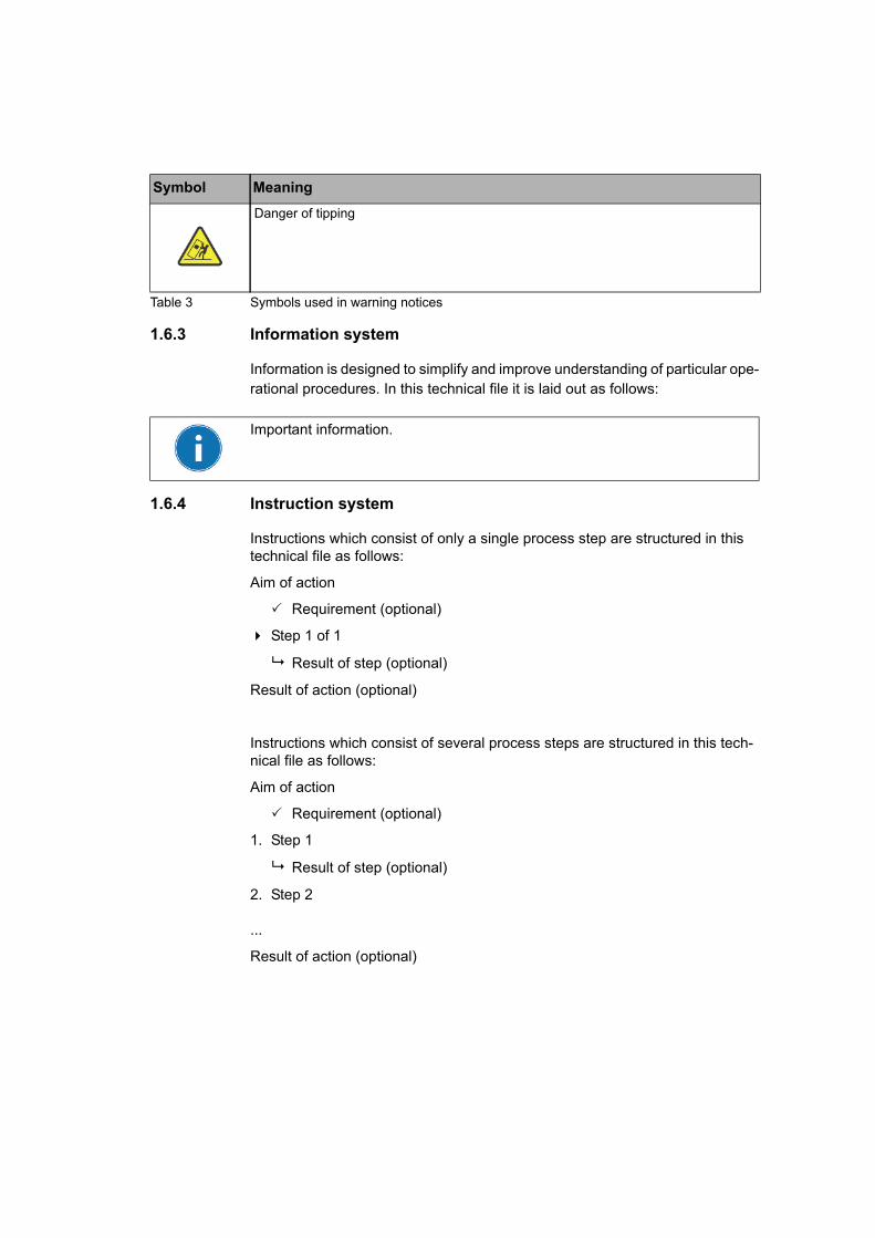
1.6.3 Information system
Information is designed to simplify and improve understanding of particular ope-rational procedures. In this technical file it is laid out as follows:
1.6.4 Instruction system
Instructions which consist of only a single process step are structured in this technical file as follows:
Aim of action
Requirement (optional)
Step 1 of 1
Result of step (optional)
Result of action (optional)
Instructions which consist of several process steps are structured in this tech-nical file as follows:
Aim of action
Requirement (optional)
1. Step 1
Result of step (optional)
2. Step 2
...
Result of action (optional)
Danger of tipping
Symbol Meaning
Table 3 Symbols used in warning notices
Important information.

1 Introduction
1.6.5 Typographic conventions
The typographic conventions in this technical file are structured as follows:
Typographic con-ventions
Meaning
...>...>... Select subsequent software menu
UPPERCASE Key labels e.g. "MENU key"
Table 4 Typographic conventions
© Maschinenfabrik Reinhausen 2009 2136339/01 EN TAPCON® 230 17


2 Safety
2 Safety
2.1 General safety information
This technical file contains important information for the safe and correct packaging, transport, storage, mounting, commissioning and simple fault elimi-nation of the product.
• Read this technical file through carefully to familiarise yourself with the pro-duct.
• Particular attention should be paid to the information given in this chapter.
2.2 Appropriate use
The product and associated equipment and special tools supplied with it comply with the relevant legislation, regulations and standards, particularly health and safety requirements, applicable at the time of delivery.
If used as intended in compliance with the specified requirements and condi-tions in this technical file as well as the warning notices in this technical file and attached to the product, then the product does not present any hazards for per-sons, property or the environment. This applies during the entire lifespan, from delivery through installation and operation to disassembly and disposal.
The operational quality assurance system ensures a consistently high quality standard, particularly when it comes to observance of the health and safety requirements.
Use is considered to be appropriate if
• the product is operated according to the agreed delivery conditions and technical data, and
• associated equipment and special tools supplied with it are used solely for the intended purpose and in accordance with the specifications of this tech-nical file.
• the product is used only for the application specified in the order.
2.3 Inappropriate use
Use is considered to be inappropriate if the product is used other than described in Chapter 2.2.
© Maschinenfabrik Reinhausen 2009 2136339/01 EN TAPCON® 230 19
2 Safety
Maschinenfabrik Reinhausen does not accept liability for damage from unau-thorised or inappropriate changes to the product. Unauthorised changes to the product without consultation with Maschinenfabrik Reinhausen can lead to per-sonal injury, material damage and operational faults.
2.4 Personnel qualification
The product is designed solely for application in electrical or energy systems and facilities operated by appropriately trained staff, i.e. staff who are familiar with the installation, assembly, commissioning and operation of such products.
2.5 Operator duty of care
To prevent accidents, faults and damage as well as unacceptable adverse effects on the environment, those responsible for transport, installation, opera-tion, maintenance and disposal of the product or parts of the product must ensure the following:
• All warning and hazard notices are complied with.
• Personnel are instructed regularly in all relevant aspects of operational safety, this technical file and particularly the safety instructions contained therein.
• Regulations and operating instructions for safe working as well as the rele-vant instructions for staff procedures in the case of accidents and fires are kept to hand at all times and displayed in the workplace where applicable.
• The product is only used in a sound operational condition and safety equip-ment in particular is checked regularly for operational reliability.
• Only replacement parts approved by the manufacturer are used.
• Comply with the specified operating conditions and requirements of the ins-tallation location.
• All necessary equipment and personal protective equipment for each activity is available.
TAPCON® 230 2136339/01 EN © Maschinenfabrik Reinhausen 200920

2 Safety
• The prescribed maintenance intervals and the relevant regulations are com-plied with.
• Fitting, electrical connection and commissioning of the product may only be carried out by qualified and trained personnel in accordance with this tech-nical file.
• The operator must ensure appropriate use of the product.
© Maschinenfabrik Reinhausen 2009 2136339/01 EN TAPCON® 230 21


3 Product description
3 Product description
3.1 Description of functions
The voltage regulation of transformers with on-load tap-changers is an impor-tant subject for energy utility companies.
The completely redesigned TAPCON® 230 voltage regulator handles both sim-ple control tasks and the complex requirements of a modern monitoring and control device.
The TAPCON® 230 voltage regulator constantly checks the actual value VActual (transformer output voltage) against a specified or load-dependent voltage level VTarget, which can be determined by the user.
The TAPCON® 230 provides the control pulse for the transformer on-load tap-changer, depending on the deviation of the actual from the voltage level.
The on-load tap-changer switches if the voltage level falls below or exceeds the specified tolerance band B (VTarget +/- B%).
The voltage at the transformer is thus kept constant. Fluctuations within the per-missible bandwidth have no influence on the control response or the tap change operation.
The voltage regulator parameters can be optimally adjusted to the line voltage behaviour, so that a balanced control response with minimum number of on-load tap changer operations is achieved.
Figure 1 shows an overview of voltage regulation using the TAPCON® 230.
© Maschinenfabrik Reinhausen 2009 2136339/01 EN TAPCON® 230 23

3 Product description
Figure 1 Overview of voltage regulation using the TAPCON® 230
TAPCON® 230 2136339/01 EN © Maschinenfabrik Reinhausen 200924

3 Product description
3.2 Features TAPCON® 230
The TAPCON® 230 handles the control of step transformers with proven reliabi-lity.
Apart from control tasks, the TAPCON® 230 provides additional functions such as:
• integrated protection functions:– undervoltage and overcurrent blocking– high-speed return in the case of overvoltage
• Line drop compensation
• Z compensation for compensating voltage fluctuations in the meshed grid
• digital inputs and outputs can be individually programmed on-site by the user
• additional indicators using LEDs external to the display for freely selectable functions
• display of all measured values such as voltage, current, active power, appa-rent power or reactive power, cos
• cable connection using modern plug terminals
• Selection of 3 different voltage levels
3.3 TAPCON® 230 pro
In addition to the functions described in Section 3.2 the TAPCON® 230 pro pro-vides additional functions such as:
• Tap position input can be selected on site between - analog signal 4 - 20 mA- analog signal over resistor contact series- digital signal using BCD or Gray code
• Additional digital inputs and outputs which can be freely parameterised by the customer
• Parallel operation of up to 6 transformers in 2 groups using the methods - Master / Follower- Circulating reactive current minimisation
The CAN bus ensures error-free data exchange between all TAPCON® devices with parallel operation over a distance of up to two kilometres.
The regulators automatically detect which transformers are in parallel operation without any supplementary equipment. By activating the binary inputs for Mas-ter/Follower/Independent or using the menu settings, the position of a transfor-mer can be quickly selected with certainty.
© Maschinenfabrik Reinhausen 2009 2136339/01 EN TAPCON® 230 25

3 Product description
3.4 TAPCON® 230 expert
In addition to the functions described in Section 3.1 and Section 3.2, the TAPCON® 230 expert provides additional functions such as:
For particularly demanding requirements the TAPCON® 230 expert also provi-des connection to a superordinate control system with protocols as shown in Table 5. RS232 and RS485 are standard and freely selectable.
Table 5 Interfaces available for control system communication
Further information on the TAPCON® 230is available on our website at:
www.tapcon230.com
RS232 RS485 LWL ETHERNETDNP3 x x x xMODBUS ASCII x x xMODBUS RTU x x x xIEC60870-5-101 x x xIEC60870-5-103 x x x
TAPCON® 230 2136339/01 EN © Maschinenfabrik Reinhausen 200926
3 Product description
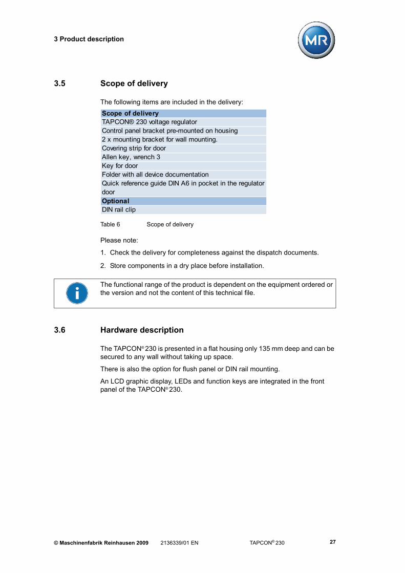
3.5 Scope of delivery
The following items are included in the delivery:
Table 6 Scope of delivery
Please note:
1. Check the delivery for completeness against the dispatch documents.
2. Store components in a dry place before installation.
3.6 Hardware description
The TAPCON® 230 is presented in a flat housing only 135 mm deep and can be secured to any wall without taking up space.
There is also the option for flush panel or DIN rail mounting.
An LCD graphic display, LEDs and function keys are integrated in the front panel of the TAPCON® 230.
Scope of deliveryTAPCON® 230 voltage regulatorControl panel bracket pre-mounted on housing2 x mounting bracket for wall mounting. Covering strip for doorAllen key, wrench 3Key for doorFolder with all device documentationQuick reference guide DIN A6 in pocket in the regulator doorOptionalDIN rail clip
The functional range of the product is dependent on the equipment ordered or the version and not the content of this technical file.
© Maschinenfabrik Reinhausen 2009 2136339/01 EN TAPCON® 230 27

3 Product description
The device is controlled by a microcontroller and includes isolated optocoupler inputs and floating output relay contacts in addition to the voltage and current transformers (Figure 2).
*communication interfaces marked green are only present in the TAPCON® 230 expert
The TAPCON® 230 can be parameterised with a PC via a COM 1 (RS232) inter-face that is integrated in the regulator and located on the front panel. The rele-vant Software can be obtained from Maschinenfabrik Reinhausen.
Figure 2 Block diagram for TAPCON® 230*
TAPCON® 230 2136339/01 EN © Maschinenfabrik Reinhausen 200928

3 Product description
The TAPCON® 230 expert also features a CI card (highlighted in green in Figure 2). The TAPCON® 230 expert can also be parameterised using this addi-tional interface. Parameterisation using the CI card requires the relevant menu settings. The additional communication interfaces are shown in Figure 3.
Figure 3 Additional communication interfaces in TAPCON® 230 expert
1 2 3 4 5
1
2
4
5
3
1 RS485 connection
2 RS232 connection
3 Fibre-optic cable connection
4 CAN bus connection
5 RJ45 connection
© Maschinenfabrik Reinhausen 2009 2136339/01 EN TAPCON® 230 29

3 Product description
The TAPCON® 230 voltage regulator is functionally compatible with earlier regu-lator generations to a large extent.
Table 7 Information on the Hardware
Manual / AutomaticRaise / LowerLocal RemoteMenu keysMonochromatic display with graphics capabilities, 128 x 128 dot6 LED green for operating status3 LED red for limit values U >, U <, I >1 LED green for parallel operation active1 LED green for NORMset active2 LED yellow for random assignment1 LED yellow/green for random assignment1 LED yellow/red for random assignment88 – 265 V AC/DCPower consumption approx. 5.0 VASteel plate housing with inspection window (lockable)Corpus (W x H) 198 x 310 mmDepth 135.5 mmDoor (W x H) 242 x 343 mmWeightpro: 6.8 kgexpert: 7.0 kgProtection degree IP 54 according to IEC 60529
Operating temperature -25°C – +70°CStorage temperature -40°C – +85°C
Display
Power supply
Protective housing
Function keys
TAPCON® 230 2136339/01 EN © Maschinenfabrik Reinhausen 200930

3 Product description
3.7 Description of the front panel
Figure 4 shows the front panel of the TAPCON® 230 with a description of the keys. Further information on the function keys is given in Chapter 3.9:
Figure 4 Front panel of the TAPCON® 230 with control panel
1 LEDs 1 - 10 9 Switching windows inside a menu level
2 Setting options for display contrast 10 Parametering interface COM 1 (RS232)
3 Labelling strip for LEDs 11 Automatic voltage regulation (with auto mode LED green)
4 F1 - F5: Function and menu selection keys
12 Manual mode (with manual control LED green)
5 Display 128X128 LCD module nega-tive blue, LED background white
13 Remote control (with Local/Remote LED green)
6 Menu selection 14 Control for RAISE/LOWER
7 Escape 15 Status LED
8 Accept entry
© Maschinenfabrik Reinhausen 2009 2136339/01 EN TAPCON® 230 31

3 Product description
3.8 Description of the display
In the case of a particular event or a setting, the comments on this are displayed in the status line (display text "Events").
Figure 5 Main screen
1
2
3
47
6 5
1 Status line
2 Actual value display in V/kV
3 Target value display in V/kV
4 Control deviation
5 Tap position display
6 Time bar
7 Target value deviation trend
TAPCON® 230 2136339/01 EN © Maschinenfabrik Reinhausen 200932
3 Product description
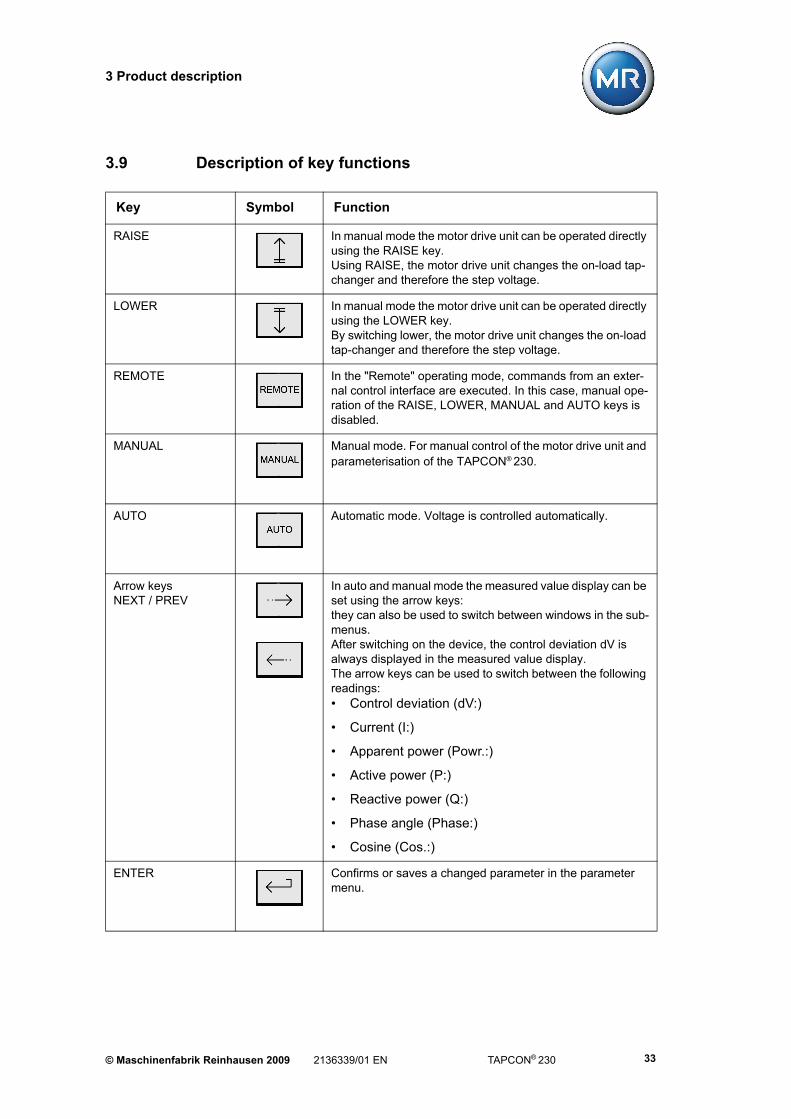
3.9 Description of key functions
Key Symbol Function
RAISE In manual mode the motor drive unit can be operated directly using the RAISE key.Using RAISE, the motor drive unit changes the on-load tap-changer and therefore the step voltage.
LOWER In manual mode the motor drive unit can be operated directly using the LOWER key.By switching lower, the motor drive unit changes the on-load tap-changer and therefore the step voltage.
REMOTE In the "Remote" operating mode, commands from an exter-nal control interface are executed. In this case, manual ope-ration of the RAISE, LOWER, MANUAL and AUTO keys is disabled.
MANUAL Manual mode. For manual control of the motor drive unit and parameterisation of the TAPCON® 230.
AUTO Automatic mode. Voltage is controlled automatically.
Arrow keysNEXT / PREV
In auto and manual mode the measured value display can be set using the arrow keys:they can also be used to switch between windows in the sub-menus.After switching on the device, the control deviation dV is always displayed in the measured value display.The arrow keys can be used to switch between the following readings:• Control deviation (dV:)
• Current (I:)
• Apparent power (Powr.:)
• Active power (P:)
• Reactive power (Q:)
• Phase angle (Phase:)
• Cosine (Cos.:)
ENTER Confirms or saves a changed parameter in the parameter menu.
© Maschinenfabrik Reinhausen 2009 2136339/01 EN TAPCON® 230 33

3 Product description
ESC Pressing the ESC key transfers you to the menu level above, in other words, always back one menu level.
MENU Pressing this key displays the menu selection window.
F1 - F5 The function keys are menu selection keys. They are also used to scroll through the menu subgroups and to mark deci-mal points which can be set by the user.
COM 1 Interface TAPCON® 230 connection to a computer.The parameterisation software is not included in the scope of delivery.
The parameters can only be changed in manual mode, see MANUAL key in the table above and Figure 4.
TAPCON® 230 2136339/01 EN © Maschinenfabrik Reinhausen 200934

3 Product description
3.10 TAPCON® 230 operating safety
The voltage regulator is equipped with a key lock as the default factory setting for protection against unintentional operation. To activate or deactivate, press the ESC and F5 keys (Figure 4) simultaneously. The key lock can be switched off using the menu.
The operating panel on the TAPCON® 230 is divided into two different levels.
These are the operation control level and the level for parameterisation and configuration.
The operation control keys are clearly separated from those for parameterisa-tion. On the operation control level, activating the keys is signalled visually by means of the LEDs.
The LEDs integrated in the RAISE/LOWER keys are illuminated during the entire tap change operation of the on-load tap-changer if "motor running" is sig-nalled at the status input. This signal requires that it has previously be parame-terised.
This visual monitoring option makes operation of the TAPCON® 230 easier.
© Maschinenfabrik Reinhausen 2009 2136339/01 EN TAPCON® 230 35


4 Packaging, transport and storage
4 Packaging, transport and storage
4.1 Packaging
4.1.1 Purpose
The packaging is designed to protect the packaged goods both during transport and for loading and unloading as well as during periods of storage in such a way that no (detrimental) changes occur. The packaging must protect the goods against permitted transport stresses such as vibration, knocks and moisture (rain, snow, condensation). The packaging also prevents unacceptable changes in the position of the content within the packaging. Before the actual packaging the products must be prepared for shipping in order to ensure that they can be transported safely, properly, and economically.
4.1.2 Suitability, structure and material
The goods are packaged in a stable cardboard box. This ensures that the con-signment is secured in the intended transport position and that none of its com-ponents touches the load platform during transport or the floor after it is unloa-ded.
The box is designed for a maximum load of 10 kg.
Inlays inside the box stabilise the goods against undue changes of position and protect them from vibration.
4.1.3 Labelling
The packaging bears symbols with instructions for safe transport and correct storage. The following symbols apply to the dispatch (of non-hazardous goods) (Figure 6). These labels must be complied with.
Figure 6 Dispatch symbols
Keep dry This way up Fragile
© Maschinenfabrik Reinhausen 2009 2136339/01 EN TAPCON® 230 37
4 Packaging, transport and storage
4.2 Transport, reception and handling of shipments
During transport the product may be subjected to stress from swinging, shock and impact. In order to prevent possible damage the product must be protected from dropping, toppling, tipping, and bouncing.
If a box is subject to a fall above a certain height or an unbroken fall, then damage will occur, depending on the weight involved.
Before acceptance, all deliveries must be checked by the recipient (acknowledgement of receipt) for
• completeness based on the delivery note
• external damage of any type.
If external transport damage is detected on receipt of the shipment, proceed as follows:
• Immediately record the transport damage in the shipping documents and have this countersigned by the carrier.
• In the event of severe damage, total loss and high damage costs immedia-tely notify the distribution division of Maschinenfabrik Reinhausen and the relevant insurance company.
• After identifying the damage do not modify the condition of the shipment further and retain the packaging material for inspection by the transport com-pany or the insurance company.
• Record the details of the damage immediately together with the carrier invol-ved. This is essential for any claim for damages.
• Take photographs of any damage to the packaging and product if possible. This also applies to signs of corrosion on the product due to moisture inside the packaging (rain, snow, condensation).
• List the damaged parts.
For concealed damage, i.e. damage that only becomes apparent after receipt of the shipment and during unpacking, proceed as follows:
• Make the party responsible for the damage liable asap by telephone and in writing, and prepare a damage report.
• Check and observe the relevant deadlines applicable in the respective coun-try.
In the case of concealed damage, recourse to the transport company (or other parties that may be responsible for the damage) may be difficult. Any claims for such damages can only be successful if associated provisions are specified in the insurance terms and conditions.
TAPCON® 230 2136339/01 EN © Maschinenfabrik Reinhausen 200938
4 Packaging, transport and storage
4.3 Storage of shipments
Selection and arrangement of the storage location should meet the following requirements:
• Stored items must be protected against moisture (flooding, melt water from snow and ice), contaminants, pests such as rats, mice, termites etc. and against unauthorised access.
• Store the box on timber beams and planks as a protection against rising damp and for better ventilation.
• The surface must have adequate load carrying capability.
• Unobstructed access must be available.
Check stored items at regular intervals, and additionally after gales, heavy rain, significant snowfall etc., and take appropriate action.
© Maschinenfabrik Reinhausen 2009 2136339/01 EN TAPCON® 230 39


5 Functions and Settings
5 Functions and Settings
This chapter describes all the functions and setting options for the voltage regu-lator. The setting values appear in the relevant sections or in summary in the table on Page 164.
The chapters are laid out following the menu structure of the device; see Figure 7.
The voltage regulator functions are set using the keys on the device. Settings can only be carried out in manual mode with deactivated key lock. The key lock is activated and deactivated by pressing ESC + F5.
Before carrying out the parameterisation, proceed as follows:
1. Deactivate the key lock if necessary. Press the ESC + F5 keys.
2. Activate manual mode: Press the MANUAL key.
3. Select main menu: Press the MENU key.
The TAPCON® 230 main menu is displayed.
The required function can now be set.
Figure 7 Menu
The key lock is activated by the voltage regulator after 15 minutes if no key has been pressed during this period. Automatic key locking requires that the func-tion "Key lock" (see Section 5.3.2 on Page 87) is activated.
The submenus are arranged in a continuous loop. For modifying functions or values, press either the F1 or F5 keys or the NEXT or PREV keys, depending on what is required.
© Maschinenfabrik Reinhausen 2009 2136339/01 EN TAPCON® 230 41

5 Functions and Settings
5.1 NORMset
Instead of parameterising the voltage regulator manually, the NORMset mode enables easy and user-friendly commissioning of the voltage regulator with a limited set of parameters. When this mode is selected, the factory settings for voltage regulation are transferred.
When commissioning the voltage regulator in NORMset mode, the following parameters must be set:
• Desired voltage level 1
• Primary voltage
• Secondary voltage
When these 3 parameters have been set, the regulator is ready to operate. The compensation settings cannot be carried out in NORMset mode. The voltage level will be compared with the measured voltage on the voltage regulator. The display can be set in V (voltage transformer secondary voltage) or kV (voltage transformer primary voltage) depending on the setting. If additional information on current and phase angle are required, connect the current transformer and adjust the current connection data (see under Section 5.3.1 “Transformer data” on page 78).
After the voltage level and voltage transformer data have been entered, if NORMset is activated the voltage regulator checks the grid conditions and auto-matically adapts additional settings, composed partly of predefined parameters and default values.
All other parameters required for simple voltage regulation are predefined in the factory.
The procedure for activating or deactivating the NORMset mode is described in the following sections.
F2
TAPCON® 230 2136339/01 EN © Maschinenfabrik Reinhausen 200942

5 Functions and Settings
5.1.1 Activating NORMset
When the NORMset mode is activated, the NORMset LED on the voltage regu-lator control panel is illuminated.
To activate the NORMset mode, proceed as follows:
1. MENU key > Normset
<00> Normset Activation
2. To activate Normset, press the F1 or F5 keys to select "On".
3. Press ENTER.
The Normset mode is now activated.
The unit V or kV has already been specified during commissioning. The display will therefore be shown in V (voltage transformer secondary voltage) or kV (vol-tage transformer primary voltage) depending on the setting. Always pay careful attention to entering the setting values correctly.
If NORMset is activated, the bandwidth and delay times which you wish to set will be ignored by the voltage regulator.
The following functions are still available in NORMset mode:
• Desired voltage level1
• Primary voltage
• Secondary voltage
The following parameters cannot be set using the NORMset mode:
• Undervoltage limit
• Overvoltage limit
• Undercurrent limit
• Overcurrent limit
If required, these parameters must be entered manually during commissioning (see Section 5.2.2 “Limit values” on page 60).
© Maschinenfabrik Reinhausen 2009 2136339/01 EN TAPCON® 230 43

5 Functions and Settings
5.1.2 Deactivating NORMset
The voltage regulator NORMset mode can be deactivated and any desired additional settings made directly.
To deactivate the NORMset mode, proceed as follows:
1. MENU key > Normset
<00> Normset Activation
2. To deactivate Normset, press the F1 or F5 key to select "Off".
3. Press ENTER.
The NORMset mode is now deactivated.
After NORMset has been deactivated, all control parameters must be checked and set manually if necessary.
TAPCON® 230 2136339/01 EN © Maschinenfabrik Reinhausen 200944

5 Functions and Settings
5.1.2.1 Setting voltage level 1
Voltage levels set in kV apply to the primary voltage of the voltage transformer. Voltage levels set in V apply to the secondary voltage of the voltage transformer. The correct transformer data must be entered. Settings in kV can only be made after the primary and secondary voltages have been entered.
To set voltage level 1, proceed as follows:
1. MENU key > Normset > 1x NEXT
<01> Desired Voltage Level 1
2. Press F4 in order to highlight the position.
The required position is now highlighted and the value can be changed.
3. Press the F1 key to increase the voltage level or F5 to decrease it.
4. Press ENTER.
Voltage level 1 is now set.
Table 8 Setting range for voltage level 1 in V in NORMset
Table 9 Setting range for voltage level 1 in kV in NORMset
Setting range Step size Factory settings49 V – 140 V 0.1 V 100 V
Setting range Step size Factory settings0 kV – 9999 kV 999.9 kV 99.99 kV
1 kV0.1 kV
0.01 kV
1 kV
© Maschinenfabrik Reinhausen 2009 2136339/01 EN TAPCON® 230 45
5 Functions and Settings
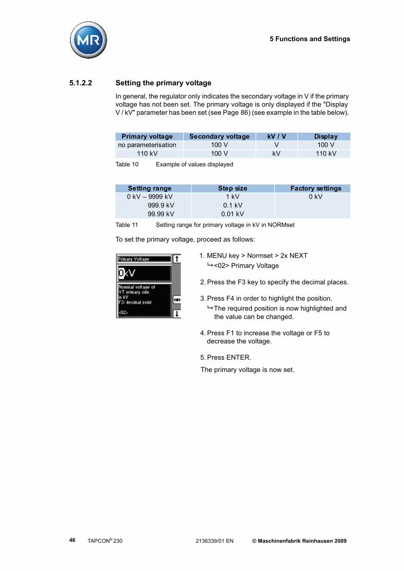
5.1.2.2 Setting the primary voltage
In general, the regulator only indicates the secondary voltage in V if the primary voltage has not been set. The primary voltage is only displayed if the "Display V / kV" parameter has been set (see Page 86) (see example in the table below).
To set the primary voltage, proceed as follows:
1. MENU key > Normset > 2x NEXT
<02> Primary Voltage
2. Press the F3 key to specify the decimal places.
3. Press F4 in order to highlight the position.
The required position is now highlighted and the value can be changed.
4. Press F1 to increase the voltage or F5 to decrease the voltage.
5. Press ENTER.
The primary voltage is now set.
Table 10 Example of values displayed
Table 11 Setting range for primary voltage in kV in NORMset
Primary voltage Secondary voltage kV / V Displayno parameterisation 100 V V 100 V
110 kV 100 V kV 110 kV
Setting range Step size Factory settings0 kV – 9999 kV 999.9 kV 99.99 kV
1 kV0.1 kV
0.01 kV
0 kV
TAPCON® 230 2136339/01 EN © Maschinenfabrik Reinhausen 200946

5 Functions and Settings
5.1.2.3 Setting the secondary voltage
The secondary voltage is displayed and entered in V.
To set the secondary voltage, proceed as follows:
1. MENU key > Normset > 3x NEXT
<03> Secondary Voltage
2. Press the F3 key to specify the decimal places.
3. Press F4 in order to highlight the position.
The required position is now highlighted and the value can be changed.
4. Press F1 to increase the voltage or F5 to decrease the voltage.
5. Press ENTER.
The secondary voltage is now set.
Table 12 Setting range for secondary voltage in V in NORMset
Setting range Step size Factory settings57 V – 123 V 0.1 V 100 V
© Maschinenfabrik Reinhausen 2009 2136339/01 EN TAPCON® 230 47

5 Functions and Settings
5.2 Control parameters
This section describes all the functions, parameters and recommended setting ranges for voltage regulation using the TAPCON® 230. To make it easier to find specific parameters, the description refers to subgroups of functionally related individual parameters.
5.2.1 Voltage regulation
This submenu contains all the parameters required for the control function.
MENU key > Regulation Param. > Voltage Regulation
5.2.1.1 Setting voltage levels
The voltage level, Vtarget is specified as a fixed value. The voltage level can be entered using the voltage regulator user interface, both in the NORMset mode subgroup and in the parameter mode subgroup (see Section 5.2).
In addition, the voltage regulator provides the option of changing the voltage level during operation if this is necessary.
The voltage levels are activated using binary inputs. Up to 3 voltage levels can be entered in the parameter mode:
• Voltage level 1
• Voltage level 2
• Voltage level 3
F3
F2
TAPCON® 230 2136339/01 EN © Maschinenfabrik Reinhausen 200948

5 Functions and Settings
Voltage level 1 is the default voltage level. Voltage levels 2 or 3 are activated if there is a continuous signal on the predefined GPIs 5 or 6. If there is a signal on both inputs simultaneously, then voltage level 2 is activated.
The following sections describe how to set the voltage levels.
5.2.1.1.1 Setting voltage level 1
Voltage levels set in kV apply to the primary voltage of the voltage transformer. Voltage levels set in V apply to the secondary voltage of the voltage transformer. The correct transformer data must be entered.
To set voltage level 1, proceed as follows:
1. MENU key > Regulation Param. > Voltage Regulation
<00> Desired Voltage Level 1
2. Press F4 in order to highlight the position.
The required position is now highlighted and the value can be changed.
3. Press F1 to increase the voltage or F5 to decrease the voltage.
4. Press ENTER.
Voltage level 1 is now set.
Table 13 Setting range for voltage level 1 in V - voltage regulation
Table 14 Setting range for voltage level 1 in kV - voltage regulation
Setting range Step size Factory settings49 V – 140 V 0.1 V 100 V
Setting range Step size Factory settings0 kV – 9999 kV 999.9 kV 99.99 kV
1 kV0.1 kV
0.01 kV
1 kV
© Maschinenfabrik Reinhausen 2009 2136339/01 EN TAPCON® 230 49

5 Functions and Settings
5.2.1.1.2 Setting voltage level 2
The voltage level 2 is activated if there is a continuous signal at GPI 5, as long as the GPI 5 was previously programmed for this. Section 5.5 describes how to program a GPI.
To set voltage level 2, proceed as follows:
1. MENU key > Regulation Param. > Voltage Regulation> 1x NEXT
<01> Desired Voltage Level 2
2. Press F4 in order to highlight the position.
The required position is now highlighted and the value can be changed.
3. Press F1 to increase the voltage or F5 to decrease the voltage.
4. Press ENTER.
Voltage level 2 is now set.
Table 15 Setting range for voltage level 2 in V - voltage regulation
Table 16 Setting range for voltage level 2 in kV - voltage regulation
Setting range Step size Factory settings49 V – 140 V 0.1 V 100 V
Setting range Step size Factory settings0 kV – 9999 kV 999.9 kV 99.99 kV
1 kV0.1 kV
0.01 kV
1 kV
TAPCON® 230 2136339/01 EN © Maschinenfabrik Reinhausen 200950

5 Functions and Settings
5.2.1.1.3 Setting voltage level 3
Voltage level 3 is activated if there is a continuous signal at GPI 6, as long as GPI 6 was previously programmed for this. Section 5.5 describes how to pro-gram a GPI.
To set voltage level 3, proceed as follows:
1. MENU key > Regulation Param. > Voltage Regulation> 2x NEXT
<02> Desired Voltage Level 3
2. Press F4 in order to highlight the position.
The required position is now highlighted and the value can be changed.
3. Press F1 to increase the voltage or F5 to decrease the voltage.
4. Press ENTER.
Voltage level 3 is now set.
Table 17 Setting range for voltage level 3 in V - voltage regulation
Table 18 Setting range for voltage level 3 in kV - voltage regulation
Setting range Step size Factory settings49 V – 140 V 0.1 V 100 V
Setting range Step size Factory settings0 kV – 9999 kV 999.9 kV 99.99 kV
1 kV0.1 kV
0.01 kV
1 kV
© Maschinenfabrik Reinhausen 2009 2136339/01 EN TAPCON® 230 51
5 Functions and Settings
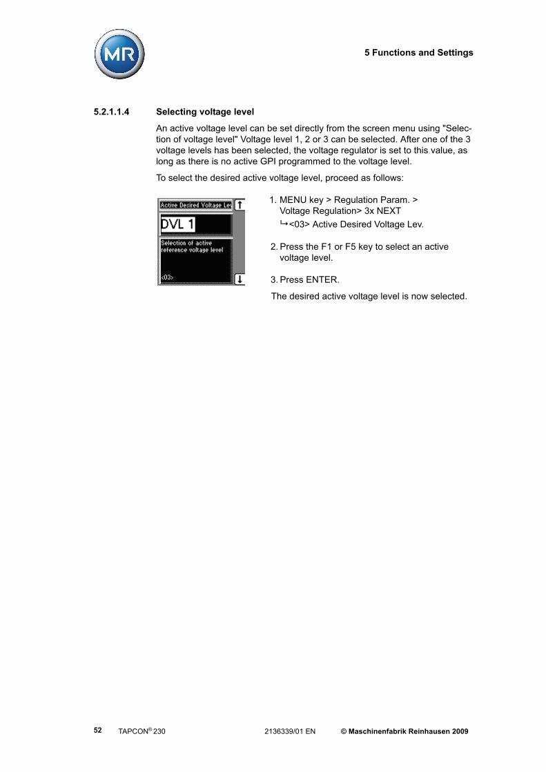
5.2.1.1.4 Selecting voltage level
An active voltage level can be set directly from the screen menu using "Selec-tion of voltage level" Voltage level 1, 2 or 3 can be selected. After one of the 3 voltage levels has been selected, the voltage regulator is set to this value, as long as there is no active GPI programmed to the voltage level.
To select the desired active voltage level, proceed as follows:
1. MENU key > Regulation Param. > Voltage Regulation> 3x NEXT
<03> Active Desired Voltage Lev.
2. Press the F1 or F5 key to select an active voltage level.
3. Press ENTER.
The desired active voltage level is now selected.
TAPCON® 230 2136339/01 EN © Maschinenfabrik Reinhausen 200952

5 Functions and Settings
5.2.1.2 Setting the bandwidth
The bandwidth is the permitted deviation of the measured voltage from the selected desired voltage level. If the measured voltage is inside the bandwidth, then no control commands are issued to the on-load tap-changer.
If the measured voltage deviates from the specified bandwidth (control devia-tion ∆V), then an output pulse occurs after the set delay time T1. The on-load tap-changer carries out a switching operation in a positive or negative direction. The deviation from the set bandwidth is shown visually by means of 2 triangles in the display. These indicate whether the measured voltage lies above, inside or below the set bandwidth. The time bar fills up gradually as soon as the vol-tage lies outside the bandwidth. The time remaining before an output pulse is emitted is also displayed
The bandwidth - i.e. the permitted positive and negative percentage deviations from the desired voltage level (Vset +/- %) - must be selected in such a way that the output voltage of the transformer (Vactual) returns within the specified tole-rance range after the tap change
If the specified bandwidth is too narrow then, if the upper limit of the bandwidth B+ % is exceeded, a switch operation downwards occurs. However, it will be switched so low that it will fall below the lower limit B- % of the bandwidth. This would result in constant switching back and forwards and also undesirable vol-tage fluctuations and additional load on the on-load tap-changer. The voltage level must on no account fall below 60% of the calculated value.
© Maschinenfabrik Reinhausen 2009 2136339/01 EN TAPCON® 230 53

5 Functions and Settings
If the value repeatedly exceeds or falls below the bandwidth and this does not stabilise after 15 minutes, then the message alert "Function monitoring" which activates the relevant relay is triggered. The message alert is only reset when the deviation returns within the set bandwidth.
In order to set the value correctly, the permitted bandwidth "B %" and the trans-former step voltage must be known.
The following value is recommended for the bandwidth "B %":
Figure 8 Deviations above and below the bandwidth
1 VActual: Measured voltage
2 VTarget: Voltage level kV/V
3 Bandwidth in %
4 T1: Set delay time (no tap change operation)
5 Exceeding the bandwidth
6 ∆V: Control deviation
UStep6,0%]B[
TAPCON® 230 2136339/01 EN © Maschinenfabrik Reinhausen 200954

5 Functions and Settings
To determine the recommended bandwidth, proceed as follows:
The calculated bandwidth is entered as follows:
1. MENU key > Regulation Param. > Voltage Regulation > 4x NEXT
<04> Bandwidth
2. Press F4 in order to highlight the position.
The required position is now highlighted and the value can be changed.
3. Press F1 to increase the value or F5 to decrease it.
4. Press ENTER.
The bandwidth is now set.
Nominal voltage: Unenn = 100 kV
Number of tap positions:
30
Control range ± 15 % (= 30 %)
Step size: Control range = 30% = 1% per step Number per step size 30 steps
Setting B± must always be in [%]
Calculation: ± B [%] = 0.6 • step size [%]± B [%] = 0.6 • 1% step size = 0.6%
Table 19 Setting range for bandwidth
Setting range Step size Factory settings0.5% – 9% 0.1 % 2 %
© Maschinenfabrik Reinhausen 2009 2136339/01 EN TAPCON® 230 55

5 Functions and Settings
5.2.1.3 Setting delay time T1
The delay time is that specified by the user. During this specified time no swit-ching operation takes place when a measured value lies outside the bandwidth. It begins as soon as the measured voltage deviates from the set tolerance range. This function prevents unnecessary tap change operations if the tole-rance range is exceeded for a short time.
If the current measured value departs from the bandwidth, then the time bar in the display fills from the bottom upwards. The time remaining up to release of the control pulse is displayed. If the control deviation - which is shown by trend triangles in the display - is still present after the delay time has elapsed, then an output pulse occurs. The duration of the delay up to the first output pulse is spe-cified using the Delay Time T1.
If the measured voltage returns within the tolerance range during the delay time, then the current delay time is counted down in seconds from the amount of time which has passed, The absolute time thus disappears from the display. The time bargraph appears as a broken line and gets steadily smaller.
If the measured voltage exceeds the set bandwidth once more whilst the time is not displayed, then the time delay is restarted from the remaining time.
The advantage of counting the time back down is that, if the bandwidth is excee-ded frequently, the regulator does not start counting again at 0 seconds, but uses the time already elapsed as the starting point for the beginning of the next delay time.
TAPCON® 230 2136339/01 EN © Maschinenfabrik Reinhausen 200956

5 Functions and Settings
To set the delay time T1, proceed as follows:
1. MENU key > Regulation Param. > Voltage Regulation> 5x NEXT
<05> Delay time T1
2. Press F4 in order to highlight the position.
The required position is now highlighted and the value can be changed.
3. Press F1 to increase the time or F5 to decrease it.
4. Press ENTER.
The delay time T1 is now set.
5.2.1.4 Setting the control response T1 (linear/integral)
The delay time T1 may be set to linear or integral. With "Linear Time" the regu-lator responds with a constant delay time which is independent of the control deviation.
If "Integral Time" is set, the delay time decreases depending on the relationship of the current control deviation to the set bandwidth B, to a minimum of 1 second. The greater the control deviation (Vactualfrom Vtarget B+/- %) the shorter the response time. This means that the voltage regulator reacts faster to unex-pectedly large voltage changes in the grid. The regulation accuracy therefore increases at the expense of switching frequency (see Figure 9 on Page 58)
Table 20 Setting range for delay time T1
Setting range Step size Factory settings0 s – 600 s 1 s 40 s
© Maschinenfabrik Reinhausen 2009 2136339/01 EN TAPCON® 230 57

5 Functions and Settings
∆V/B - voltage change "∆V" in % of the voltage level is related to the set band-width "B" in % of the desired voltage level.
To set the control response T1, proceed as follows:
1. MENU key > Regulation Param. > Voltage Regulation> 6x NEXT
<06> Characteristics T1
2. Press F5 to select "linear" or F1 to select "integral".
3. Press ENTER.
The control response T1 is now set.
Figure 9 ∆V/B voltage change
1 Control deviation
2 Parameter "T1 integral"
TAPCON® 230 2136339/01 EN © Maschinenfabrik Reinhausen 200958
5 Functions and Settings
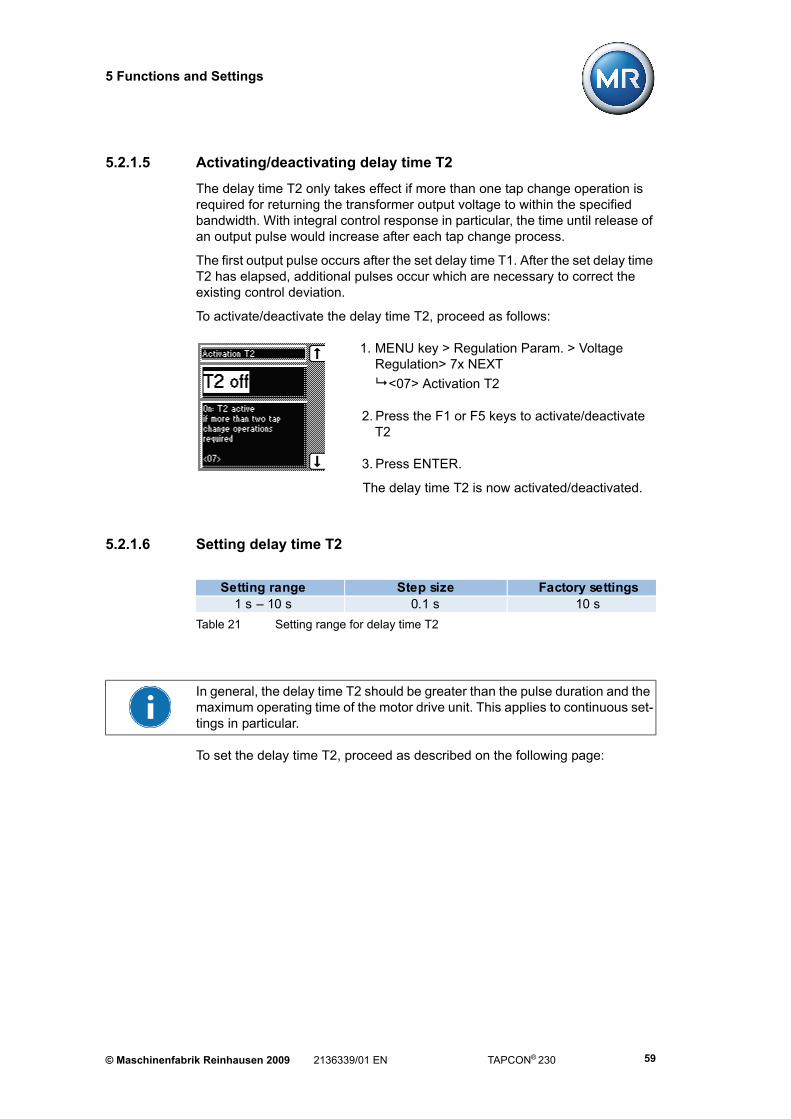
5.2.1.5 Activating/deactivating delay time T2
The delay time T2 only takes effect if more than one tap change operation is required for returning the transformer output voltage to within the specified bandwidth. With integral control response in particular, the time until release of an output pulse would increase after each tap change process.
The first output pulse occurs after the set delay time T1. After the set delay time T2 has elapsed, additional pulses occur which are necessary to correct the existing control deviation.
To activate/deactivate the delay time T2, proceed as follows:
1. MENU key > Regulation Param. > Voltage Regulation> 7x NEXT
<07> Activation T2
2. Press the F1 or F5 keys to activate/deactivate T2
3. Press ENTER.
The delay time T2 is now activated/deactivated.
5.2.1.6 Setting delay time T2
To set the delay time T2, proceed as described on the following page:
Table 21 Setting range for delay time T2
Setting range Step size Factory settings1 s – 10 s 0.1 s 10 s
In general, the delay time T2 should be greater than the pulse duration and the maximum operating time of the motor drive unit. This applies to continuous set-tings in particular.
© Maschinenfabrik Reinhausen 2009 2136339/01 EN TAPCON® 230 59

5 Functions and Settings
1. MENU key > Regulation Param. > Voltage Regulation> 8x NEXT
<08> Delay Time T2
2. Press F1 to increase the time or F5 to decrease it.
3. Press ENTER.
The delay time T2 is now set.
5.2.2 Limit values
This subgroup contains all the parameters required for monitoring the limit values. The limit values are set as percentage values.
MENU key > Regulation Param. > Limit Values
For the undervoltage and overvoltage parameters, the inputs are basically determined by the specified desired voltage level. For overcurrent and under-current, the values are defined by the desired voltage level of the current trans-former i.e. the selected current transformer connection.
F3 F3
TAPCON® 230 2136339/01 EN © Maschinenfabrik Reinhausen 200960

5 Functions and Settings
5.2.2.1 Setting the limit value V< Undervoltage (%)
Undervoltage blocking prevents tap change operations if there is a power cut. The voltage regulator output pulses are blocked and the red "V<" LED lights up as soon as the measured voltage falls below the set blocking value.
If the measured voltage falls below the set limit value, the signalling relay comes into operation after the set V< undervoltage delay (MIO-X1-3/3 terminals).
To set the undervoltage blocking, proceed as follows:
1.MENU key > Regulation Param. > Limit Values
<00> Undervoltage V< [%]
2. Press F1 to increase the value or F5 to decrease it.
3. Press ENTER.
The undervoltage blocking V< is now set.
Table 22 Setting range for V< undervoltage blocking
Setting range Step size Factory settings60 % – 100 %
of desired value1 % 90 %
© Maschinenfabrik Reinhausen 2009 2136339/01 EN TAPCON® 230 61

5 Functions and Settings
5.2.2.2 Setting the V< undervoltage delay
To prevent the undervoltage relay activating immediately a short-lived voltage dip occurs, a delay time can be set for this signal. The undervoltage LED will light up immediately in any case.
To set this signal delay, proceed as follows:
1. MENU key > Regulation Param. > Limit Values >1x NEXT
<01> Delay Time V<
2. Press F4 in order to highlight the position.
The required position is now highlighted and the value can be changed.
3. Press F1 to increase the time or F5 to decrease it.
4. Press ENTER.
The undervoltage delay V< is now set.
Table 23 Setting range for V< undervoltage delay
Setting range Step size Factory settings0 s – 20 s 0.1 s 10 s
TAPCON® 230 2136339/01 EN © Maschinenfabrik Reinhausen 200962

5 Functions and Settings
5.2.2.3 Activating/deactivating V< undervoltage blocking
The undervoltage blocking can be activated or deactivated. If blocking is deac-tivated and the value falls below that specified, then only a signal appears via the relay and LED. However, the control is not blocked.
To activate/deactivate the undervoltage blocking, proceed as follows:
1. MENU key > Regulation Param. > Limit Values >2x NEXT
<02> Blocking Undervolt. V<
2. Press the F1 or F5 keys to activate/deactivate blocking.
3. Press ENTER.
V< undervoltage blocking is now activated/deactivated.
5.2.2.4 Disabling V< undervoltage signal <30 V
Disabling the "V< undervoltage" signal can be useful in order to avoid error sig-nals when the transformer is switched off (Measured voltage V< 30 V at the regulator).
To disable the V< undervoltage signal, proceed as follows:
1. MENU key > Regulation Param. > Limit Values >3x NEXT
<03> V< Below 30 V
2. Press the F1 key to disable the undervoltage signal.
3. Press ENTER.
The V< undervoltage signal is now disabled.
© Maschinenfabrik Reinhausen 2009 2136339/01 EN TAPCON® 230 63
5 Functions and Settings
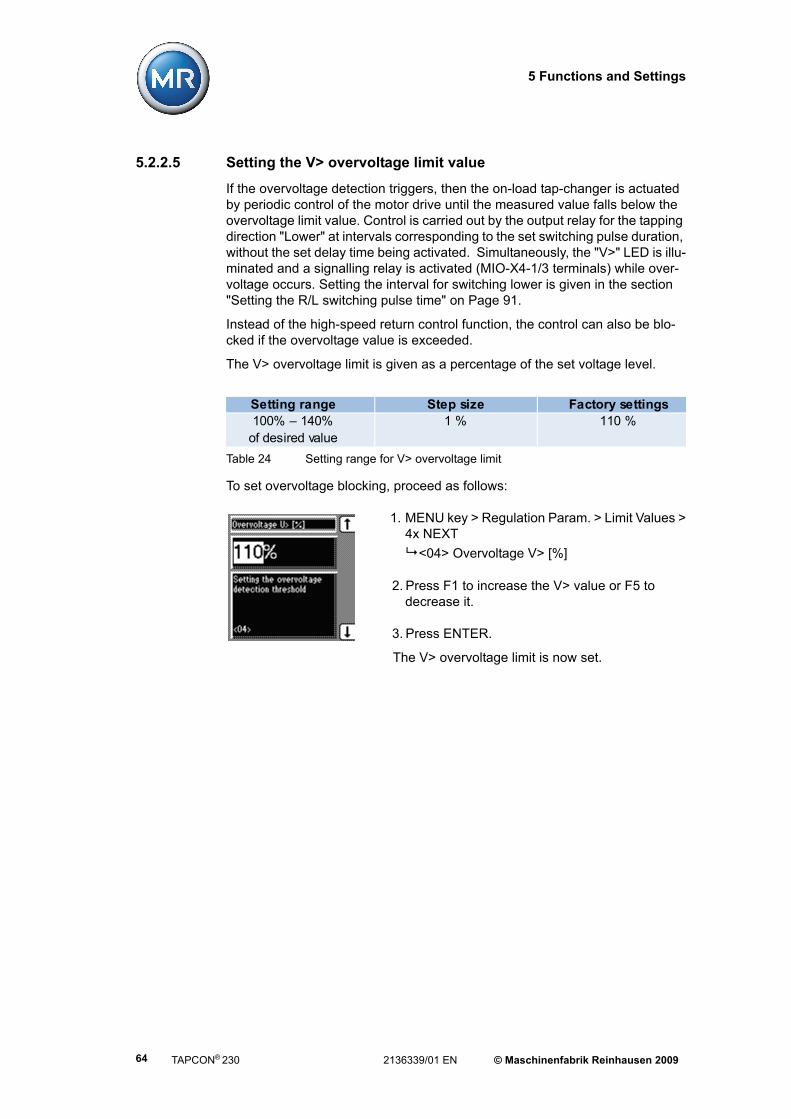
5.2.2.5 Setting the V> overvoltage limit value
If the overvoltage detection triggers, then the on-load tap-changer is actuated by periodic control of the motor drive until the measured value falls below the overvoltage limit value. Control is carried out by the output relay for the tapping direction "Lower" at intervals corresponding to the set switching pulse duration, without the set delay time being activated. Simultaneously, the "V>" LED is illu-minated and a signalling relay is activated (MIO-X4-1/3 terminals) while over-voltage occurs. Setting the interval for switching lower is given in the section "Setting the R/L switching pulse time" on Page 91.
Instead of the high-speed return control function, the control can also be blo-cked if the overvoltage value is exceeded.
The V> overvoltage limit is given as a percentage of the set voltage level.
To set overvoltage blocking, proceed as follows:
1. MENU key > Regulation Param. > Limit Values >4x NEXT
<04> Overvoltage V> [%]
2. Press F1 to increase the V> value or F5 to decrease it.
3. Press ENTER.
The V> overvoltage limit is now set.
Table 24 Setting range for V> overvoltage limit
Setting range Step size Factory settings100% – 140%
of desired value1 % 110 %
TAPCON® 230 2136339/01 EN © Maschinenfabrik Reinhausen 200964
5 Functions and Settings
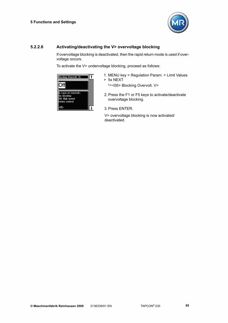
5.2.2.6 Activating/deactivating the V> overvoltage blocking
If overvoltage blocking is deactivated, then the rapid return mode is used if over-voltage occurs.
To activate the V> undervoltage blocking, proceed as follows:
1. MENU key > Regulation Param. > Limit Values > 5x NEXT
<05> Blocking Overvolt. V>
2. Press the F1 or F5 keys to activate/deactivate overvoltage blocking.
3. Press ENTER.
V> overvoltage blocking is now activated/deactivated.
© Maschinenfabrik Reinhausen 2009 2136339/01 EN TAPCON® 230 65

5 Functions and Settings
5.2.2.7 Setting limit value I> overcurrent
The I> overcurrent blocking prevents tap change operations during load cur-rents which are higher than the selected limit value (e.g. overload).
As soon as the measured current exceeds the set blocking value, control is blo-cked. The "I>" LED lights up and the relevant signalling relay is activated (MIO-X4-1/3 terminals-1/3).
The set limit value is entered in % and only becomes active when overcurrent blocking is activated.
To set the limit value I> overcurrent for overcurrent blocking, proceed as follows:
1. MENU key > Regulation Param. > Limit Values >6x NEXT
<06> Overcurrent I> [%]
2. Press F1 to increase the value or F5 to decrease it.
3. Press ENTER.
The limit value I> overcurrent is now set
The I> overcurrent blocking can now be activated (see Section 5.2.2.8).
Table 25 Setting range for I> overcurrent blocking
Setting range Step size Factory settings50 % – 210 % 1 % 110 %
TAPCON® 230 2136339/01 EN © Maschinenfabrik Reinhausen 200966

5 Functions and Settings
5.2.2.8 Activating/deactivating the I> overcurrent blocking
After setting the limit value for the I> overcurrent blocking (see Section 5.2.2.7), the I> overcurrent blocking can be set. When the overcurrent blocking is deac-tivated, only the I> LED lights up and the relevant signalling relay is activated. Regulation continues.
To activate the I> overcurrent blocking, proceed as follows:
1. MENU key > Regulation Param. > Limit Values > 7x NEXT
<07> Blocking Overcurrent I>
2. Press the F1 or F5 keys to activate/deactivate overvoltage blocking.
3. Press ENTER.
The I> overcurrent blocking is activated/deactivated.
© Maschinenfabrik Reinhausen 2009 2136339/01 EN TAPCON® 230 67
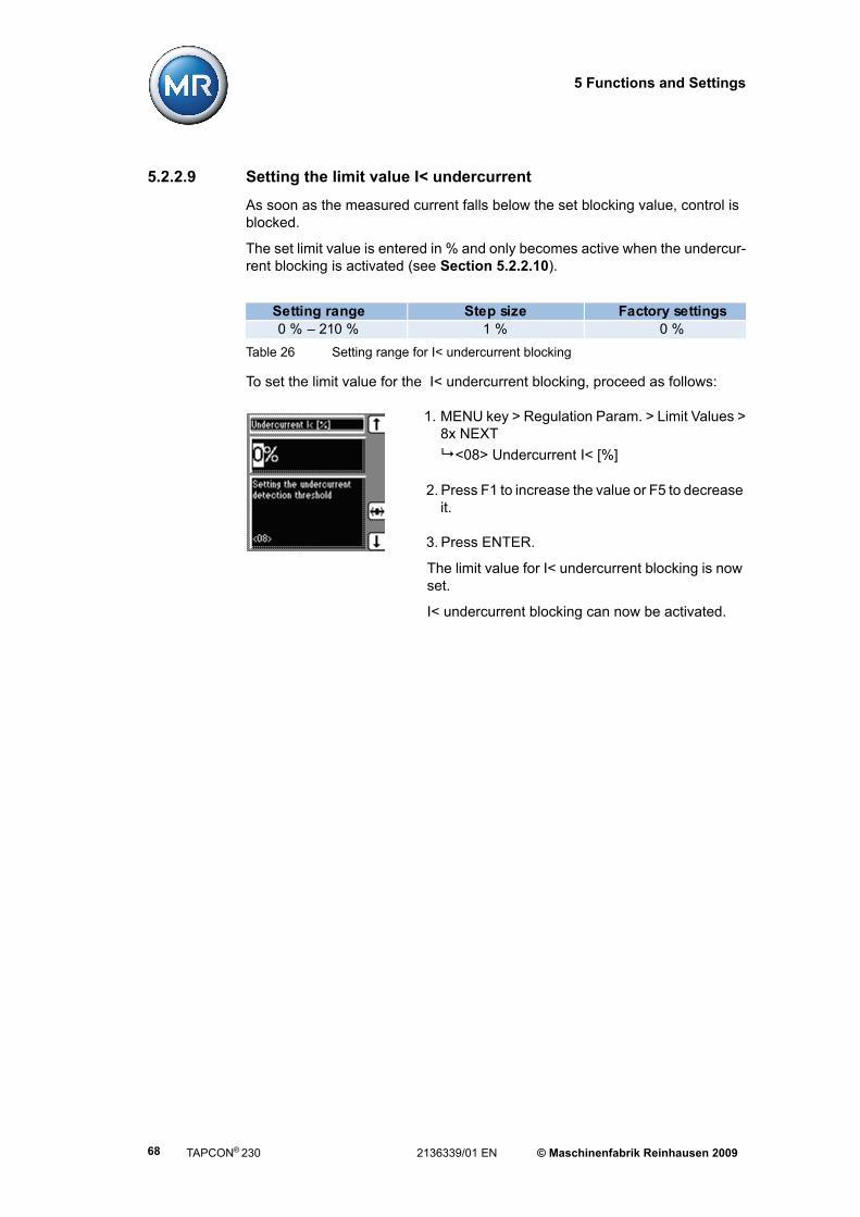
5 Functions and Settings
5.2.2.9 Setting the limit value I< undercurrent
As soon as the measured current falls below the set blocking value, control is blocked.
The set limit value is entered in % and only becomes active when the undercur-rent blocking is activated (see Section 5.2.2.10).
To set the limit value for the I< undercurrent blocking, proceed as follows:
1. MENU key > Regulation Param. > Limit Values >8x NEXT
<08> Undercurrent I< [%]
2. Press F1 to increase the value or F5 to decrease it.
3. Press ENTER.
The limit value for I< undercurrent blocking is now set.
I< undercurrent blocking can now be activated.
Table 26 Setting range for I< undercurrent blocking
Setting range Step size Factory settings0 % – 210 % 1 % 0 %
TAPCON® 230 2136339/01 EN © Maschinenfabrik Reinhausen 200968

5 Functions and Settings
5.2.2.10 Activating/deactivating I< undercurrent blocking
After setting the limit value for the I< undercurrent blocking (see Section 5.2.2.9), the I< undercurrent blocking can be set. When the undercurrent blo-cking is deactivated, only the I< LED lights up and the relevant signalling relay is activated. Regulation continues.
To activate the I< undercurrent blocking, proceed as follows:
1. MENU key > Regulation Param. > Limit Values >9x NEXT
<09> Blocking Undercurr. I<
2. Press the F1 or F5 keys to activate (On) / deactivate (Off) the blocking.
3. Press ENTER.
The I< undercurrent blocking is activated/deactivated.
5.2.2.11 Activating/deactivating the regulator blocking with negative active power
When the regulator blocking is activated, the control is blocked if a negative active power flow is detected. However, this is only possible if the current trans-former connection is connected and correctly set. When the regulator blocking is deactivated, then the sign of the active power does not affect the regulation.
To activate/deactivate the regulator blocking, proceed as follows:
1. MENU key > Regulation Param. > Limit Values >10x NEXT
<10> Neg. Active Power Block.
2. Press the F1 or F5 keys to activate (ON) / deactivate (OFF) the blocking.
3. Press ENTER.
Blocking the regulator with negativeactive power is now activated/deactivated.
© Maschinenfabrik Reinhausen 2009 2136339/01 EN TAPCON® 230 69
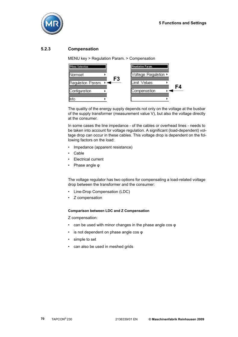
5 Functions and Settings
5.2.3 Compensation
MENU key > Regulation Param. > Compensation
The quality of the energy supply depends not only on the voltage at the busbar of the supply transformer (measurement value V), but also the voltage directly at the consumer.
In some cases the line impedance - of the cables or overhead lines - needs to be taken into account for voltage regulation. A significant (load-dependent) vol-tage drop can occur in these cables. This voltage drop is dependent on the fol-lowing factors on the load:
• Impedance (apparent resistance)
• Cable
• Electrical current
• Phase angle φ
The voltage regulator has two options for compensating a load-related voltage drop between the transformer and the consumer:
• Line-Drop Compensation (LDC)
• Z compensation
Comparison between LDC and Z Compensation
Z compensation:
• can be used with minor changes in the phase angle cos φ
• is not dependent on phase angle cos φ
• simple to set
• can also be used in meshed grids
F3
F4
TAPCON® 230 2136339/01 EN © Maschinenfabrik Reinhausen 200970

5 Functions and Settings
Line-Drop Compensation (vectorial compensation):
• provides more precise compensation of line voltage drops
• requires several parameters
• requires full knowledge of the line data
Both options are described in more detail in the following sections.
5.2.3.1 Line-Drop Compensation (LDC)
Line drop compensation requires exact line data. Line voltage drops can be compensated very accurately using LDC.
To set the LDC correctly requires calculation of the ohmic and inductive voltage drops, related to the secondary side of the voltage transformer in V. Correct set-ting of the existing measuring circuit is also necessary.
The setting values must first be calculated in order to enter the correct values for the ohmic and inductive voltage drops. The following apply:
Formula for calculating the ohmic voltage drop:
Formula for calculating the inductive voltage drop:
Vr LDC setting for ohmic line voltage drop in V
Vx LDC setting for inductive line voltage drop in V
IN Nominal current in A of selected current transformer connection on the voltage regulator, i.e. 1 A or 5 A
VCT Current transformer ratio, e.g. 1 A or 5 A
VVT Voltage transformer ratio, e.g.:
r Ohmic line resistance in Ω/km per phase
x Inductive line resistance in Ω/km per phase
L Length of line in km
V1003V30000
Ur INUCTUVT--------- r L V =
Ux INUCTUVT--------- x L V =
© Maschinenfabrik Reinhausen 2009 2136339/01 EN TAPCON® 230 71

5 Functions and Settings
If the active and reactive voltage drops "Vr" and "Vx" are set correctly, then the
voltage at the line end remains constant irrespective of the load.
The settings for the compensation methods are described in more detail below:
Figure 10 Line drop equivalent circuit
Figure 11 Line-Drop Compensation
TAPCON® 230 2136339/01 EN © Maschinenfabrik Reinhausen 200972
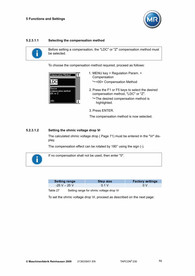
5 Functions and Settings
5.2.3.1.1 Selecting the compensation method
To choose the compensation method required, proceed as follows:
1. MENU key > Regulation Param. > Compensation
<00> Compensation Method
2. Press the F1 or F5 keys to select the desired compensation method, "LDC" or "Z".
The desired compensation method is highlighted.
3. Press ENTER.
The compensation method is now selected.
5.2.3.1.2 Setting the ohmic voltage drop Vr
The calculated ohmic voltage drop ( Page 71) must be entered in the "Vr" dis-play.
The compensation effect can be rotated by 180° using the sign (-).
To set the ohmic voltage drop Vr, proceed as described on the next page:
Before setting a compensation, the "LDC" or "Z" compensation method must be selected.
If no compensation shall not be used, then enter "0".
Table 27 Setting range for ohmic voltage drop Vr
Setting range Step size Factory settings-25 V – 25 V 0.1 V 0 V
© Maschinenfabrik Reinhausen 2009 2136339/01 EN TAPCON® 230 73

5 Functions and Settings
1. Select compensation method "LDC" (see Page 73).
2. Press 1x NEXT.
<01> Line Drop Compensation Vr
3. Press F4 in order to highlight the position.
The required position is now highlighted and the value can be changed.
4. Press F1 to increase the value or F5 to decrease it.
5. Press ENTER.
The Vr voltage drop is now set.
5.2.3.1.3 Setting the inductive voltage drop Vx
The calculated inductive voltage drop (see Page 71) must be entered in the "Vx" display. The compensation effect can be rotated by 180° using the sign (-).
To set the inductive voltage drop Vx, proceed as described on the next page:
If no compensation shall not be used, then enter "0".
Table 28 Setting range for inductive voltage drop Vx
Setting range Step size Factory settings-25 V – 25 V 0.1 V 0 V
TAPCON® 230 2136339/01 EN © Maschinenfabrik Reinhausen 200974

5 Functions and Settings
1. Select compensation method "LDC" (see Page 73).
2. Press 2x NEXT
<02> Line Drop Compensation Vx
3. Press the F4 key to select the decimal place.
The required position is now highlighted and the value can be changed.
4. Press F1 to increase the value or F5 to decrease it.
5. Press ENTER.
The inductive voltage drop Vx is now set.
5.2.3.1.4 Setting Z compensation voltage increase
Z compensation can be used for example for minor changes to the phase angle cos φ. It can also be used for meshed grids. Z compensation is not dependent on cos φ.
To set the parameter correctly it is necessary to calculate the voltage rise (ΔV) taking the current into account.
Calculation of the required setting values:
Formula for determining the voltage rise ΔV:
ΔV Setting the Z compensation in %
VTr Transformer voltage with current I
VLoad Voltage at end of line with current 1 and the same operating position of the on-load tap-changer
I Load current in A
IN Nominal current in A of selected current transformer connection on the voltage regulator; 1 A or 5 A
VCT Current transformer ratio, e.g. 200 A /5 A
U UTr ULa–ULoad
-----------------------IN UCTI
--------------------=100%
© Maschinenfabrik Reinhausen 2009 2136339/01 EN TAPCON® 230 75

5 Functions and Settings
The voltage increase percentage is calculated in relation to the desi.
To set the Z compensation, proceed as follows:
1. Select the compensation method "Z" (see Page 73.
2. Press 1x NEXT.
<03> Z - Comp. Volt Rise
3. Press F1 to increase the value or F5 to decrease it.
4. Press ENTER.
The Z compensation is now set.
If no compensation shall not be used, then enter "0".
Table 29 Setting range for Z compensation
Setting range Step size Factory settings0 % – 15 %vom Sollwert
0.1 % 0 %
TAPCON® 230 2136339/01 EN © Maschinenfabrik Reinhausen 200976

5 Functions and Settings
5.2.3.1.5 Setting the Z compensation limit value ΔV
To set a particular compensation value, but nevertheless avoid the voltage in the transformer becoming too high (e.g. with exceptionally high loading), then a limit can be set on the maximum permitted voltage increase in relation to the voltage level.
To set the limit value ΔV, proceed as follows:
1. Select the compensation method "Z" (see Page 73)
2. Press 2x NEXT.
<04> Z Comp. Limit
3. Press F1 to increase the value or F5 to reduce it.
4. Press ENTER.
The Z-Comp. Limit ΔV is now set.
Table 30 Setting range for Z compensation limit value ΔV
Setting range Step size Factory settings0 % – 15 %vom Sollwert
0.1 % 0 %
© Maschinenfabrik Reinhausen 2009 2136339/01 EN TAPCON® 230 77
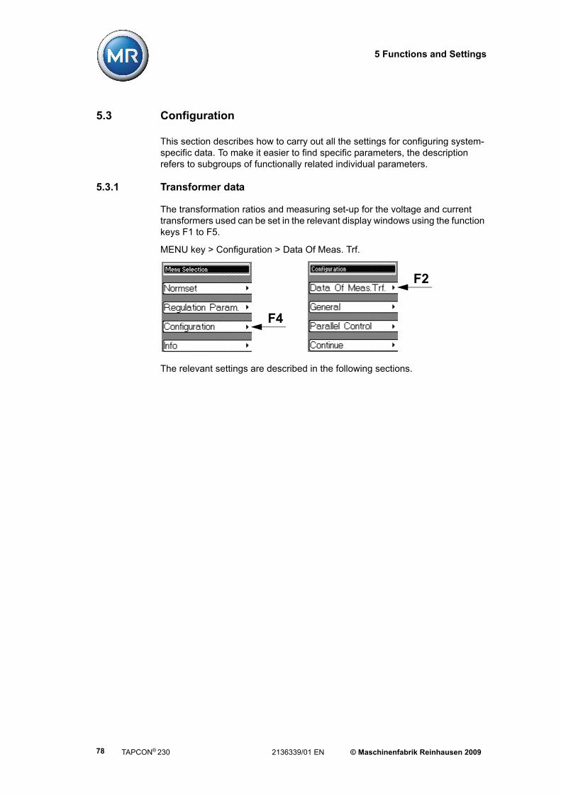
5 Functions and Settings
5.3 Configuration
This section describes how to carry out all the settings for configuring system-specific data. To make it easier to find specific parameters, the description refers to subgroups of functionally related individual parameters.
5.3.1 Transformer data
The transformation ratios and measuring set-up for the voltage and current transformers used can be set in the relevant display windows using the function keys F1 to F5.
MENU key > Configuration > Data Of Meas. Trf.
The relevant settings are described in the following sections.
F4
F2
TAPCON® 230 2136339/01 EN © Maschinenfabrik Reinhausen 200978

5 Functions and Settings
5.3.1.1 Setting the primary transformer voltage
In general, the regulator only displays the secondary transformer voltage in V if the primary transformer voltage has not been set. The primary voltage is only displayed if the "Display V /kV" parameter has been set (see example in the table below).
To set the primary transformer voltage, proceed as follows:
1. MENU key > Configuration > Data Of Meas. Trf.
<00> Primary Voltage
2. Press the F3 key to specify the decimal places.
3. Press F4 in order to highlight the position.
The required position is now highlighted and the value can be changed.
4. Press F1 to increase the value or F5 to decrease it.
5. Press ENTER.
The primary transformer voltage is now set.
Table 31 Example of displayed values kV / V
Table 32 Setting range for primary transformer voltage
Primary voltage Secondary voltage kV / V Displayno parameterisation 100 V V 100 V
110 kV 100 V kV 110 kV
Setting range Step size Factory settings0 kV – 9999 kV 999.9 kV 99.99 kV
1 kV0.1 kV
0.01 kV
0 kV
© Maschinenfabrik Reinhausen 2009 2136339/01 EN TAPCON® 230 79

5 Functions and Settings
5.3.1.2 Setting the secondary transformer voltage
The secondary transformer voltage is displayed and entered in V.
To set the secondary transformer voltage, proceed as follows:
1. MENU key > Configuration > Transformer data > 1x NEXT
<01> Secondary Voltage
2. Press F4 in order to highlight the position.
The required position is now highlighted and the value can be changed.
3. Press F1 to increase the value or F5 to decrease it.
4. Press ENTER.
The secondary transformer voltage is now set.
5.3.1.3 Setting the primary transformer current
In general the regulator indicates the percentage current of the chosen measu-red input of the regulator (1 A and 5 A). Immediately the primary measurement current (e.g. 50 A) has been entered in the regulator, the display in the Info menu switches over to "A" (amperes). The primary current is always displayed in "A" on the main screen or with "0" if no primary current is specified.
The exact display for each setting is shown in the table on Page 81:
Table 33 Setting range for secondary transformer voltage
Setting range Step size Factory settings57 V – 123 V 0.1 V 100 V
TAPCON® 230 2136339/01 EN © Maschinenfabrik Reinhausen 200980

5 Functions and Settings
To set the primary transformer current, proceed as described below:
1. MENU key > Configuration > Transformer data > 2x NEXT
<02> Primary Current
2. Press F1 to increase the value or F5 to decrease it.
3. Press F4 in order to highlight the position.
The required position is now highlighted and the value can be changed.
4. Press F1 to increase the value or F5 to decrease it.
5. Press ENTER.
The primary transformer current is now set.
Table 34 Example of unit displayed: % / A
Current feedPrimary current
Secondary current
Powerconnection
Info screen Primary/secondary
current
Main screen
noparameterisatio
Unknown 1 A 100 % 0 A
noparameterisatio
1 A 1 A 1 A 0 A
50 A Unknown 1 A 100 %(of primary current)
50 A(of primary current)
50 A 1 A 1 A 1 A(of secondary current)
50 A(of secondary current)
Setting parameter Display
Table 35 Setting range for primary transformer current
Setting range Step size Factory settings0 A – 9,999 A 1 A 0 A
© Maschinenfabrik Reinhausen 2009 2136339/01 EN TAPCON® 230 81

5 Functions and Settings
5.3.1.4 Setting the current transformer connection
The current transformer terminal must be selected in order to obtain the correct display. If the "CT Terminal" is set to "Unknown", the percentage value is shown. However, if a terminal (1 A or 5 A) is selected, the absolute value in "A" (ampere) is displayed.
To set the current transformer connection, proceed as follows:
1. MENU key > Configuration > Transformer data > 3x NEXT
<03> CT Terminal
2. Press the F1 key or F5 key to select the required terminal..
3. Press ENTER.
The current transformer connection is now set.
TAPCON® 230 2136339/01 EN © Maschinenfabrik Reinhausen 200982
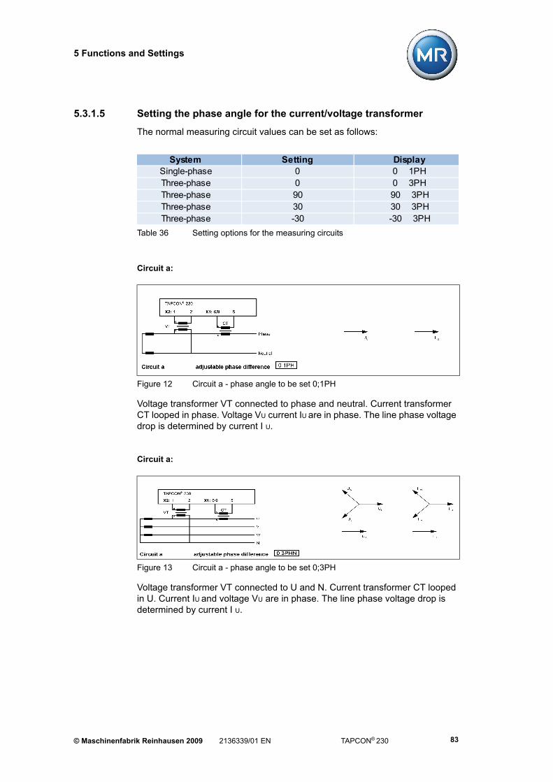
5 Functions and Settings
5.3.1.5 Setting the phase angle for the current/voltage transformer
The normal measuring circuit values can be set as follows:
Circuit a:
Voltage transformer VT connected to phase and neutral. Current transformer CT looped in phase. Voltage VU current IU are in phase. The line phase voltage drop is determined by current I U.
Circuit a:
Voltage transformer VT connected to U and N. Current transformer CT looped in U. Current IU and voltage VU are in phase. The line phase voltage drop is determined by current I U.
Table 36 Setting options for the measuring circuits
System Setting DisplaySingle-phase 0 0 1PHThree-phase 0 0 3PHThree-phase 90 90 3PHThree-phase 30 30 3PHThree-phase -30 -30 3PH
Figure 12 Circuit a - phase angle to be set 0;1PH
Figure 13 Circuit a - phase angle to be set 0;3PH
© Maschinenfabrik Reinhausen 2009 2136339/01 EN TAPCON® 230 83

5 Functions and Settings
Circuit b:
Voltage transformer VT connected to U and V. Current transformer CTI looped in U and CT2in V. Current transformer CT1and CT2 are connected crosswise in parallel (current summation IU + IV). Current IU+ IV and voltage VU Vare in phase. The line phase voltage drop is determined by current (IU + IV)/v3.
Circuit c:
Voltage transformer VT connected to U and V. Current transformer CT looped in W. Current IW leads voltage VU V by 90°. The line phase voltage drop is deter-mined by current I W.
Figure 14 Circuit b - phase angle to be set 0;3PH
Figure 15 Circuit c - phase angle to be set 90;3PH
TAPCON® 230 2136339/01 EN © Maschinenfabrik Reinhausen 200984

5 Functions and Settings
Circuit d:
Voltage transformer VT connected to U and V. Current transformer CT looped in V. Current IW leads voltage VU V by 30°. The line phase voltage drop is deter-mined by current I V.
Circuit e:
Voltage transformer VT connected to U and V. Current transformer CT looped in U. Current IU lags behind voltage VU V by -30°. The line phase voltage drop is determined by current I U.
To set the phase angle for the measured transformer circuit, proceed as follows:
1. MENU key > Configuration > Transformer data > 4x NEXT
<04> Meas. Transformer Circuit
2. Press the F1 key or F5 key to select the required phase angle
3. Press ENTER.
The phase is now set.
Figure 16 Circuit d - phase angle to be set 30;3PH
Figure 17 Circuit e - phase angle to be set 30;3PH
© Maschinenfabrik Reinhausen 2009 2136339/01 EN TAPCON® 230 85

5 Functions and Settings
5.3.1.6 Setting the voltage display kV / V
Switching the display to kV converts and displays the measurement and setting values in the device on the primary page of the voltage transformer. The voltage display has already been set during commissioning. However, the primary side is always displayed in kV and the secondary side always in V.
To change the desired voltage display, proceed as follows:
1. MENU key > Configuration > Transformer data > 5x NEXT
<05> Display kV / V
2. Press the F1 or F5 keys to select the unitskV or V.
3. Press ENTER.
The voltage display is now set.
5.3.1.7 Setting the current display unit % / A
The limit values for overcurrent and undercurrent can be displayed in percenta-ges or in amperes as required.
To set the unit to % / A , proceed as follows:
1. MENU key > Configuration > Data Of Meas. Trf. >6x NEXT
<06> Display % / A
2. Press the F1 or F5 key for "A" ampere or"%" to select a percentage value.
3. Press ENTER.
The required unit is now set.
It is only possible to change from V to kV if all the transformer data have been entered.
TAPCON® 230 2136339/01 EN © Maschinenfabrik Reinhausen 200986

5 Functions and Settings
5.3.2 General
This submenu enables general settings to be made on the device. Some set-ting, such as e.g. language, have already been specified during commissioning. The following settings can be changed:
• Language
• Regulator ID
• Baud rate
• Pulse duration
• Operation Counter
• Display dimming
• Key lock
• Monitoring
• Motor runtime
• Manual and automatic mode
• Local und Remote
MENU key > Configuration > General
Each of the settings is described in more detail in the following sections.
F4
F3
© Maschinenfabrik Reinhausen 2009 2136339/01 EN TAPCON® 230 87
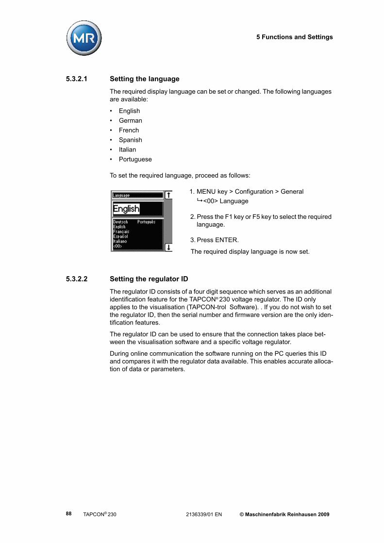
5 Functions and Settings
5.3.2.1 Setting the language
The required display language can be set or changed. The following languages are available:
• English
• German
• French
• Spanish
• Italian
• Portuguese
To set the required language, proceed as follows:
1. MENU key > Configuration > General
<00> Language
2. Press the F1 key or F5 key to select the required language.
3. Press ENTER.
The required display language is now set.
5.3.2.2 Setting the regulator ID
The regulator ID consists of a four digit sequence which serves as an additional identification feature for the TAPCON® 230 voltage regulator. The ID only applies to the visualisation (TAPCON-trol Software). . If you do not wish to set the regulator ID, then the serial number and firmware version are the only iden-tification features.
The regulator ID can be used to ensure that the connection takes place bet-ween the visualisation software and a specific voltage regulator.
During online communication the software running on the PC queries this ID and compares it with the regulator data available. This enables accurate alloca-tion of data or parameters.
TAPCON® 230 2136339/01 EN © Maschinenfabrik Reinhausen 200988

5 Functions and Settings
To set the regulator ID, proceed as follows:
1. MENU key > Configuration > General > 1x NEXT
<01> AVR ID
2. Press F1 to change the first digit.
If you wish to enter a multidigit sequence, continueto step 3. If you do not wish to enter additionaldigits, proceed to step 7:
3. Press the F1 key repeatedly (> 9) until a further digit position appears.
4. Press F4 in order to highlight a digit position to be changed.
The required digit is highlighted and can be changed.
5. Press F1 or F5 to change the digit.
6. Repeat steps 3 to 5 until all required digits have been entered.
7. Press ENTER.
The regulator ID is now set.
© Maschinenfabrik Reinhausen 2009 2136339/01 EN TAPCON® 230 89

5 Functions and Settings
5.3.2.3 Setting the baud rate
This submenu can be used to specify the baud rate for the COM1 interface (communication to TAPCON-trol® Software). The following values can be set:
• 9.6 kilobaud
• 19.2 kilobaud
• 38.4 kilobaud
• 57.6 kilobaud
To set the baud rate, proceed as follows:
1. MENU key > Configuration > General > 2x NEXT
<02> Baud Rate
2. Press the F1 key or F5 key to select the required baud rate.
3. Press ENTER.
The baud rate is now set.
TAPCON® 230 2136339/01 EN © Maschinenfabrik Reinhausen 200990

5 Functions and Settings
5.3.2.4 Setting the Raise/Lower switching pulse time
This submenu can be used to set the duration of the switching pulse for the motor drive unit
In standard operating mode, the minimum time T1 or T2 always occurs between the switching pulses. If the R/L switching pulse time is set to e.g. 1.5 seconds, then a 1.5 second long switching pulse takes place (see Figure 18) after the set delay time T1 or T2 has passed.
In the Quick Tap mode the next switching pulse can only take place after 1.5 seconds (see Figure 19 on Page 92).
If the R/L switching pulse time is set to 0, then a continuous pulse is issued.
If the motor drive unit does not start using the default setting (1.5 seconds), then increase the pulse time.
Figure 18 Switching pulse in standard operating mode
U
0 t [s]
TI
T1 T1 T1
TI
1 32 4
1 T1 = Set delay time for switching pulse (40 seconds)
2 First R/L switching pulse
3 T1 = Switching pulse duration (1.5 seconds)
4 Earliest subsequent switching pulse (after 40 seconds)
© Maschinenfabrik Reinhausen 2009 2136339/01 EN TAPCON® 230 91

5 Functions and Settings
To set the pulse time, proceed as follows:
1. MENU key > Configuration > General > 3x NEXT
<03> Pulse Time
2. Press the F1 key or F5 key to select the required pulse time.
3. Press ENTER.
The R/L pulse time is now set.
Figure 19 Switching pulse in Quick Tap mode
U
0 t [s]
TI TI TI
1 32
1 First R/L switching pulse
2 TI = Set time for switching pulse
3 Earliest time for the next R/L switching pulse
Table 37 Setting range for R/L switching pulse time
Setting range Step size Factory settings0 s – 10 s 0.1 s 1.5 s
TAPCON® 230 2136339/01 EN © Maschinenfabrik Reinhausen 200992

5 Functions and Settings
5.3.2.5 Operation Counter
As soon as a switching operation is initiated by the voltage regulator, the voltage regulator receives feedback via the "Motor running" signal". This detects whe-ther the motor is active. The tap-change operation counter counts the number of pulses of the motor drive unit if a GPI has been parameterised to "Motor run-ning".
To activate this display, proceed as follows:
1. MENU key > Configuration > General > 4x NEXT
<04> Operation Counter
2. Press the F1 key to increase the value or F5 to lower it.
3. Press ENTER.
The operation counter is now set.
5.3.2.6 Switching the background illumination for the display on/off
If this function is activated, the display is automatically dimmed if no key is pressed within a period of 15 minutes. However, the display can still be read. Activating this function increases the lifespan of the display. The display returns to full brightness by pressing any key.
1. MENU key > Configuration > General > 5x NEXT
<05> Display Dimming
2. Press the F1 key or F5 key to switch on (ON) / switch off (OFF) display dimming.
3. Press ENTER.
The background illumination on the display is now activated/deactivated.
Table 38 Operation Counter setting range
Setting range Step size Factory settings0…99,999,999 1 0
© Maschinenfabrik Reinhausen 2009 2136339/01 EN TAPCON® 230 93

5 Functions and Settings
5.3.2.7 Activating/deactivating the automatic key lock
If the automatic key lock is activated, then the device locks automatically after 15 minutes if no key has been pressed. This function can be activated or deac-tivated as required.
To activate/deactivate the key lock, proceed as follows:
1. MENU key > Configuration > General > 6x NEXT
<06> Key Lock
2. Press the F1 or F5 keys to activate (ON)/deactivate (OFF) the automatic key lock.
3. Press ENTER.
The key lock is now activated/deactivated
5.3.2.8 Disabling function monitoring
If the measured value leaves the set bandwidth (voltage level +/- bandwidth) for more than 15 minutes, the function monitoring relay is activated. This results in a message alert on the display which is only reset when the measured value returns within the current bandwidth.
If there is no measured voltage (i.e. < 30 V), then the measured value is outside the bandwidth and the relevant relay is also activated after 15 minutes. This function can be deactivated if required, in case the voltages fall below 30 V:
1. MENU key > Configuration > General > 7x NEXT<07> Function Monitoring
2. Press the F1 key or F5 key to switch on (on) / switch off (off) the function monitoring.
3. Press ENTER.
The function monitoring is now activated/deactivated for voltages <30 V.
TAPCON® 230 2136339/01 EN © Maschinenfabrik Reinhausen 200994

5 Functions and Settings
5.3.2.9 Setting the motor runtime
The motor drive runtime is monitored by the voltage regulator via the "Motor running" input. This input is not parameterised at the factory and must first be assigned by the user. The function of the runtime monitoring is described in more detail using an example in the following section and in Figure 20 on Page 96:
As soon as the motor is running, the "motor running" feedback signal is received (1; 6) The motor then runs for approx. 5 seconds. If the motor runs for longer than the specified motor runtime (runtime monitoring), the regulator conti-nuously activates the relay "motor runtime exceeded" (3). At the same time, the "trip motor protection switch" relay is activated for approx. 1.5 seconds and therefore emits a pulse (7; 8). The "trip motor protection switch" pulse emitted by the relay should give a signal at the "trip motor protection switch" GPI. In other words, the motor protection switch should be triggered (4).
As soon as the motor protection switch is switched on, the "Motor protection switch triggered" signal should disappear and the "motor runtime exceeded" relay should therefore be opened again (9).
To obtain the correct function, the relevant GPIs and GPOs (see position num-bers 1 to 4 in Figure 20 must first be correctly parameterised and connected. The procedure for parameterising the GPIs and GPOs is given in Section 5.5.1 and Section 5.5.2.
© Maschinenfabrik Reinhausen 2009 2136339/01 EN TAPCON® 230 95

5 Functions and Settings
If the pulse from the "Trigger motor protection switch" relay does not trigger the motor protection switch, then the "pulse" will be issued as often as required until the "Trigger motor protection switch" relay is activated or the motor protection switch is switched on.
Figure 20 Motor runtime set to 10 seconds
1
2
3
4
5 6 7 98
1 GPI feedback signal: "Motor running"
2 GPO signal: "Trigger motor protection switch"
3 GPO signal: "Motor runtime exceeded"
4 GPI feedback signal: "Motor protection switch in motor drive unit triggered"
5 Motor drive unit stationary
6 Feedback signal: Motor running
7 Feedback signal: Motor runtime exceeded
8 Signal: Motor protection switch was triggered
9 Feedback signal: Motor protection switch in motor drive unit switched on
TAPCON® 230 2136339/01 EN © Maschinenfabrik Reinhausen 200996
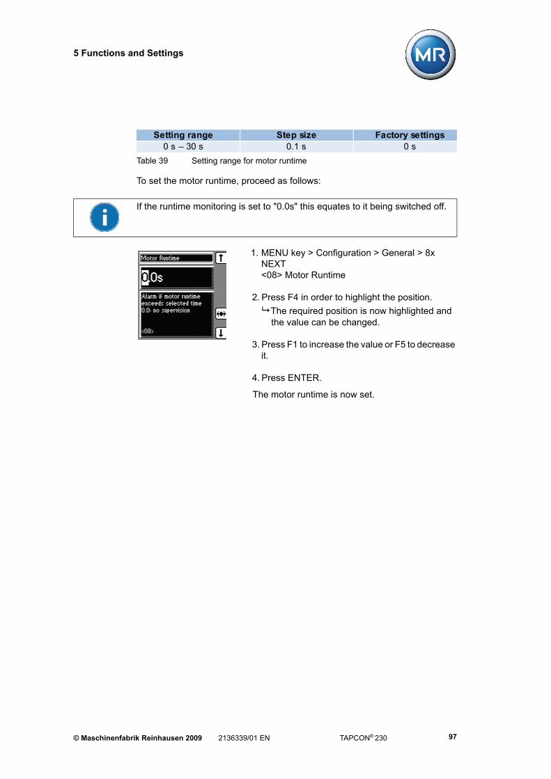
5 Functions and Settings
To set the motor runtime, proceed as follows:
1. MENU key > Configuration > General > 8x NEXT<08> Motor Runtime
2. Press F4 in order to highlight the position.
The required position is now highlighted and the value can be changed.
3. Press F1 to increase the value or F5 to decrease it.
4. Press ENTER.
The motor runtime is now set.
Table 39 Setting range for motor runtime
Setting range Step size Factory settings0 s – 30 s 0.1 s 0 s
If the runtime monitoring is set to "0.0s" this equates to it being switched off.
© Maschinenfabrik Reinhausen 2009 2136339/01 EN TAPCON® 230 97

5 Functions and Settings
5.3.2.10 Activating manual/automatic mode
This parameter has the same functions as the MANUAL key for manual mode and the AUTO key for automatic mode on the front panel of the device. Manual or automatic mode can be set using the keys or via the display.
To activate manual or automatic mode, proceed as follows:
1. MENU key > Configuration > General > 9x NEXT<09> Manual / Auto
2. Press the F1 key or F5 key to activate the manual (Manual) or automatic (Auto) modes.
3. Press ENTER.
Manual or automatic mode is not set.
5.3.2.11 Activating Local/Remote
This parameter has the same function as the REMOTE key on the front panel of the device. The REMOTE function can be set using the appropriate key or via the display.
If "Local" is activated, then the device can be operated directly using the front panel, while "Remote" only allows remote control via the inputs or the control system. If a TAPCON® 230 expert voltage regulator is available, then the com-munication interface can also be used for remote control.
To activate "Local" or "Remote", proceed as follows:
1. MENU key > Configuration > General > 10x NEXT
<10> Local / Remote
2. Press the F1 key or F5 key to activate "Local" or "Remote".
3. Press ENTER.
Local/ Remote is now set.
TAPCON® 230 2136339/01 EN © Maschinenfabrik Reinhausen 200998

5 Functions and Settings
5.4 Parallel control
MENU key > Configuration > Parallel Control
Mains power supply sometimes requires an increase in the short circuit capacity or the throughput capacity at a site. For this reason, step transformers are con-nected in parallel.
A safer and more cost effective parallel operating mode is achieved if the joint capacity of the transformers connected in parallel is utilised without the over-load of individual transformers.
The voltage regulator enables control of up to 6 transformers connected in par-allel in one or 2 groups. Information exchange is carried out using the CAN bus. Parallel operation is activated using one of 2 status inputs or the control system.
There are 2 reasons for setting up parallel operating mode:
1. To increase the short circuit capacity
2. To increase the throughput capacity
F4 F4
Compliance with the following general conditions is recommended for opera-ting transformers in parallel:
• Identical rated voltage
• Ratio of transformer power ratings (< 3:1)
• Maximum deviation of short-circuit voltages (VK) for transformers connected in parallel ≤10 %
• Identical vector group specification
© Maschinenfabrik Reinhausen 2009 2136339/01 EN TAPCON® 230 99

5 Functions and Settings
5.4.1 Activate Parallel Operation
Before activating parallel operation, additional requirements must be met:
Correct individual CAN bus addresses must be set (not equal to 0) (see Section 5.4.5)
The parallel operation group 1 or 2 must be selected or activated using a predefined GPI (see Section 5.5.1).
1. MENU key > Configuration > Parallel Control
<00> Parallel Control Enable
2. Press the F1 or F5 key to activate parallel operation.
3. Press ENTER.
Parallel operation is now activated.
Further settings for parallel operation can be car-ried out.
5.4.2 Disabling parallel operation
To disable parallel operation proceed as follows:
1. MENU key > Configuration > Parallel Control
<00> Parallel Control Enable
2. Press the F1 or F5 key to disable parallel operation.
3. Press ENTER.
Parallel operation is now disabled.
TAPCON® 230 2136339/01 EN © Maschinenfabrik Reinhausen 2009100

5 Functions and Settings
5.4.3 Parallel operation method
The parallel operation methods which can be selected and set are described in the following sections. Four different methods can be assigned to the voltage regulators:
Circulating reactive current
• Recommended transformer data
• No tap position input required
Tap synchronization (master/follower)
• Transformers with identical ratings
• Tap position input required
Automatic tap synchronization
5.4.3.1 Selecting circulating reactive current sensitivity
When circulating reactive current is selected, then parallel operation is carried out using the circulating reactive current minimisation method.
The circulating reactive current is calculated from the transformer currents and their phase angles. A voltage proportional to the circulating reactive current is added to the independently operating voltage regulators as a correction for the measurement voltage. This voltage correction can be reduced or increased using the "circulating reactive current sensitivity" setting.
This method is suitable for transformers with similar nominal output, nominal voltage Vk and a vector group with equal and unequal step voltage. This does not require any information about the tap position.
© Maschinenfabrik Reinhausen 2009 2136339/01 EN TAPCON® 230 101

5 Functions and Settings
To select the "circulating reactive current" parallel operation method, proceed as follows:
1. MENU key > Configuration > Parallel Control > 1x NEXT
<01> Parallel operation method
2. Press the F1 key or F5 key repeatedly until "Circ. current" appears in the display.
3. Press ENTER.
The parallel operation method "Circulating reactive current" is now selected.
When setting the "circulating reactive current" method, the values for blocking and circulating reactive current sensitivity must first be set (see Section 5.4.6 “Activating/deactivating stand-alone blocking” on page 107 and Section 5.4.7 “Setting circulating reactive current sensitivity” on page 108).
TAPCON® 230 2136339/01 EN © Maschinenfabrik Reinhausen 2009102

5 Functions and Settings
5.4.3.2 Defining the master tap synchronization method
In this method the voltage regulator is designated as the master. The regulator takes over control while all other follower regulators comply with the control commands of the master.
The master compares the tap positions of the followers with its own tap position using the CAN bus. If there is a tap difference, the master directs the followers to be adjusted to the same tap position.
If the specified master fails, then the error message "Parallel operation error: no master available" appears. In addition, depending on the configuration of the "Simplex mode blocking" parameter (see Section 5.4.9), those regulators which are set accordingly are blocked or continue in simplex mode.
To specify the "master" parallel operation method, proceed as follows:
1. MENU key > Configuration > Parallel Control > 1x NEXT
<01> Parallel operation method
2. Press the F1 key or F5 key repeatedly until "Master" appears in the display.
3. Press ENTER.
The "master" parallel operation method is now specified.
Please note that each voltage regulator is assigned an address using the "CAN Address" submenu. Only when all voltage regulators have been registered can they communicate with one another using the CAN bus and use the "master/follower" method.
© Maschinenfabrik Reinhausen 2009 2136339/01 EN TAPCON® 230 103

5 Functions and Settings
5.4.3.3 Specifying the follower tap synchronization method
In this method the voltage regulator is designated as the follower. This regulator receives the control commands from the master and has to comply with these (see Section 5.4.3.2).
To define the "Follower" parallel operation method, proceed as follows:
1. MENU key > Configuration > Parallel Control > 1x NEXT
<01> Parallel operation method
2. Press the F1 key or F5 key repeatedly until "Follower" appears in the display.
3. Press ENTER.
The "Follower" parallel operation method is now defined.
5.4.3.4 Selecting automatic tap synchronization
In this master/follower method, the voltage regulator with the lowest CAN address - of all the voltage regulators on the CAN bus within the same parallel operation group - is automatically selected as master. This regulator undertakes the measurement and adjusts the on-load tap-changer in order to correct the voltage if a deviation occurs.
As in the master method, the voltage regulator compares the tap position of the follower with its own using the CAN bus. If there is a tap difference, the voltage regulator directs the followers to be adjusted to the same tap position.
If there is a tap position difference between the master and follower which is lar-ger than the maximum set tap difference (Section 5.4.12), then the "Parallel operation error" signal is issued and automatic regulation is blocked.
TAPCON® 230 2136339/01 EN © Maschinenfabrik Reinhausen 2009104

5 Functions and Settings
To select the "Automatic tap synchronization" parallel operation method, pro-ceed as follows:
1. MENU key > Configuration > Parallel Operation >
1x NEXT
<01> Parallel operation method
2. Press the F1 key or F5 key repeatedly until "AutoSynchr." appears in the display.
3. Press ENTER.
The automatic synchronization parallel operation method is now selected.
Please note that each voltage regulator is assigned an address using the "CAN Address" submenu. Only when all voltage regulators have been registered can they communicate with one another using the CAN bus and can use the "Auto-matic Synchronization" method.
© Maschinenfabrik Reinhausen 2009 2136339/01 EN TAPCON® 230 105

5 Functions and Settings
5.4.4 Assigning paralleling group
A transformer group can be assigned to the voltage regulator using the "Paral-lelling Group" display. The "Group 1 and group 2" setting enables the voltage regulator to be assigned to 2 groups simultaneously. The groups can be formed as follows:
To assign the paralleling group, proceed as follows:
1. MENU key > Configuration > Parallel Control > 2x NEXT
<02> Paralleling Group
2. Press the F1 key or F5 key repeatedly until the required function appears in the display.
3. Press ENTER.
The paralleling group is now set.
Table 40 Assigning paralleling group
The paralleling group can only be selected using the menu if no allocation has been carried out using a GPI.
Setting FunctionNone Voltage regulator not assigned to any groupGroup 1 Voltage regulator assigned to group 1Group 2 Voltage regulator assigned to group 2Group 1 and group 2 Voltage regulator assigned to group 1 and group 2
TAPCON® 230 2136339/01 EN © Maschinenfabrik Reinhausen 2009106

5 Functions and Settings
5.4.5 Entering the CAN Address
So that all voltage regulators can communicate using the CAN bus, each vol-tage regulator requires a unique identifier. Addresses can be set from 1 to 16. If the value is set to 0, then no communication takes place.
To enter the CAN address, proceed as follows:
1. MENU key > Configuration > Parallel Operation > 3x NEXT
<03> CAN Address
2. Press F1 to increase the CAN address number or F5 to decrease it.
3. Press ENTER.
The CAN address has now been entered.
5.4.6 Activating/deactivating stand-alone blocking
If a parallel group with several voltage regulators has been defined, then the blocking function is available. This function is activated on the voltage regulator if no other voltage regulator in the group is recognised using the CAN bus.
"Stand-alone blocking" can be activated if single regulation of the voltage regu-lator needs to be avoided.
To activate/deactivate blocking, proceed as follows:
1. MENU key > Configuration > Parallel Control > 4x NEXT
<04> Stand-alone Blocking
2. Press the F1 or F5 keys to activate (On) or deactivate (Off) blocking.
3. Press ENTER.
The blocking is now activated/deactivated
© Maschinenfabrik Reinhausen 2009 2136339/01 EN TAPCON® 230 107

5 Functions and Settings
5.4.7 Setting circulating reactive current sensitivity
The circulating reactive current sensitivity is a measure of the effect of the cir-culating reactive current on the behaviour of the voltage regulator. With a setting of 0 % there is no effect. For a circulating reactive current equal to the rated cur-rent of the current transformer, a setting value of 10 % would effect a voltage correction of 10 % for the voltage regulators This setting can be used to reduce or increase the voltage correction.
To set the circulating reactive current sensitivity, proceed as follows:
1. MENU key > Configuration > Parallel Control > 5x NEXT
<05> Circ. Current Sensitivity
2. Press F1 to increase the value or F5 to decrease it.
3. Press the F4 key to select the decimal place.
The decimal place is now highlighted and the value can be changed.
4. Press ENTER.
The circulating reactive current sensitivity is now set.
Table 41 Setting range for circulating reactive current sensitivity.
Setting range Step size Factory settings0 % – 100 % 1 % 0 %
TAPCON® 230 2136339/01 EN © Maschinenfabrik Reinhausen 2009108

5 Functions and Settings
5.4.8 Setting the blocking threshold for the maximum permitted circula-ting reactive current
This sets the threshold for the maximum permitted circulating current in relation to the current transformer nominal current. If, during parallel operation, the cir-culating current exceeds the set threshold, then the "Parallel operation error" event is activated. As a result, all voltage regulators operating in parallel are blo-cked. Depending on the set delay time, the "Parallel operation fault" signalling relay is activated (GPO4 by default). To set the delay time for the parallel ope-ration error message, see Section 5.4.10 “Setting the delay time for the parallel operation error message” on page 111.
To set the blocking threshold for the maximum permitted circulating current, pro-ceed as follows:
1. MENU key > Configuration > Parallel Control > 6x NEXT
<06> Circ. Current Blocking
2. Press F1 to increase the value or F5 to decrease it.
3. Press F4 in order to highlight the position.
The required position is now highlighted and the value can be changed.
4. Press ENTER.
The blocking threshold for the maximum permitted circulating current is now set.
Table 42 Setting range for circulating current blocking
Setting range Step size Factory settings0.5 % – 40 % 0.1 % 20 %
© Maschinenfabrik Reinhausen 2009 2136339/01 EN TAPCON® 230 109

5 Functions and Settings
5.4.9 Activating/deactivating master/follower current blocking
This monitoring function is available with the parallel operation method "Master/follower synchronized tap-change operation" along with a current measure-ment. If the circulating current reaches the threshold set in Section 5.4.8, then the voltage regulator is blocked.
To activate/deactivate the current blocking, proceed as follows:
1. MENU key > Configuration > Parallel Control > 7x NEXT
<07> Master/Foll. Curr. Block.
2. Press the F1 or F5 key to activate (On)/deactivate (Off) the blocking.
3. Press ENTER.
The master/follower current blocking is activated/deactivated.
TAPCON® 230 2136339/01 EN © Maschinenfabrik Reinhausen 2009110

5 Functions and Settings
5.4.10 Setting the delay time for the parallel operation error message
If the voltage regulator detects an error during parallel operation, then the mes-sage "Parallel operation error" is issued.
If a parallel operation error occurs, then the relevant LED immediately lights up. The signal is only issued at the GPO4 after the set delay time.
To set the delay time for the parallel operation error message, proceed as fol-lows:
1. MENU key > Configuration > Parallel Control > 8x NEXT
<08>Delay Parallel Failure
2. Press F1 to increase the value or F5 to decrease it.
3. Press ENTER.
The delay time for the parallel operation error message is now set.
Table 43 Setting range for parallel operation error message delay time
Setting range Step size Factory settings1 s – 99s 1 s 10 s
© Maschinenfabrik Reinhausen 2009 2136339/01 EN TAPCON® 230 111

5 Functions and Settings
5.4.11 Selecting the follower tapping direction
As in parallel mode the tap positions of the transformers which are running in parallel with one another are compared according to the "master/follower" method, it is absolutely essential that these transformers have the same posi-tion designation and that the "Raise" or "Lower" signals produce the same vol-tage change in all transformers.
If it should happen that the follower regulator(s) switch(es) the master regulator step change in the opposite direction, then this parameter setting must be chan-ged from "Default" to "Swapped".
To select the tapping direction, proceed as follows:
1. MENU key > Configuration > Parallel Control > 9x NEXT
<09> Follower Tapping Direction
2. Press the F1 key or F5 key to select the required tapping direction.
3. Press ENTER.
The follower tapping direction is now selected.
Please note whether the voltage regulator has been designated as master or follower when setting the tapping direction. Swapping the tapping direction can only be carried out for the follower.
TAPCON® 230 2136339/01 EN © Maschinenfabrik Reinhausen 2009112

5 Functions and Settings
5.4.12 Setting the maximum tap difference
The aim of the tap synchronization method is to set the same tap position for all transformers connected in parallel. This function allows the maximum permitted tap difference to be specified should a deviation in the tap position occur. If this threshold is reached during operation, the regulator emits the signal "Parallel operation error" and blocks.
A difference of up to 4 tap positions can be set.
To set the maximum tap difference, proceed as follows:
1. MENU key > Configuration > Parallel Control > 10x NEXT
<10> Max. Tap Difference
2. Press F1 to increase the value or F5 to decrease it.
3. Press ENTER.
The maximum tap difference is now set.
Table 44 Setting range for permitted tap difference
Setting range Step size Factory settings0 – 4 1 1
© Maschinenfabrik Reinhausen 2009 2136339/01 EN TAPCON® 230 113

5 Functions and Settings
5.4.13 Activating/deactivating follower tapping without measuring vol-tage
If the follower does not have a measuring voltage or an existing voltage measu-rement has no function, this function can be used to define whether the voltage regulator should block in this situation or should continue to carry out the mas-ter’s control commands.
To activate/deactivate this function, proceed as follows:
1. MENU key > Configuration > Parallel Control > 11x NEXT
<11> Foll. Tapping w/o Vmeas
2. Press the F1 or F5 keys to activate (On) or deactivate (Off) the Function.
3. Press ENTER.
The function is now activated/deactivated
TAPCON® 230 2136339/01 EN © Maschinenfabrik Reinhausen 2009114

5 Functions and Settings
5.5 Assigning freely configurable inputs/outputs
This section describes the user inputs and outputs. Functions can be assigned to the GPIs and GPOs in accordance with the Table 45 on Page 116 if required.
MENU key > Configuration > Continue > User I/Os
F4F5
F3
© Maschinenfabrik Reinhausen 2009 2136339/01 EN TAPCON® 230 115

5 Functions and Settings
5.5.1 Assigning inputs (GPIs)
The following functions are available for the GPIs:
The procedure for assigning the functions is described in the following sections.
To assign functions to the GPIs, proceed as follows
(Example GPI 1 - X4:13):
1. MENU key > Configuration > ContinueUser I/Os
<00> GPI 1 - X4:13
2. Press the F1 key or F5 key repeatedly until the required function appears in the display.
3. Press ENTER.
The function is now assigned.
Table 45 Function options for GPIs
Function options Description of functions1 Off No function selected2 Master/Foll. Master mode active when signal on; Follower
mode active when signal off3 Remote/Loc. "Remote" mode active when signal on; "Local"
mode active when signal off4 Blocking Automatic regulation blocked5 Quick Tap T1/T2 deactivated. Raise/lower pulse takes place
immediately if value falls below or exceeds bandwidth
6 MPS tripped Message: Motor protection switch triggered7 MD in progr. Message: Motor running8 DVL 2 Voltage level 2 activated9 DVL 3 Voltage level 3 activated
10 Remote VL Remote setting of voltage level activated11 ParGroup1 Regulator in group 1 during parallel operation12 ParGroup2 Regulator in group 2 during parallel operation13 Blk U raise Raise pulse blocked14 Blk U low Lower pulse blocked
TAPCON® 230 2136339/01 EN © Maschinenfabrik Reinhausen 2009116

5 Functions and Settings
All additional GPIs can be assigned as described on Page 116. The following GPIs are available:
Table 46 Freely-configurable GPIs
GPI Press NEXT key Page number in the displayGPI 1 - X4:13 – <00>GPI 2 - X4:14 1x <01>GPI 3 - X4:15 2x <02>GPI 4 - X4:16 3x <03>GPI 5 - X4:17 4x <04>GPI 6 - X4:18 5x <05>GPI 7 - X6:1 6x <06>GPI 8 - X6:2 7x <07>
© Maschinenfabrik Reinhausen 2009 2136339/01 EN TAPCON® 230 117

5 Functions and Settings
5.5.2 Assigning outputs (GPOs)
A relay can be assigned a function using the GPOs. Should the assigned event occur, then the relevant message will appear on the screen. These messages are only for information. The following functions are available for the GPOs:
The procedure for assigning the functions is described in the following sections.
Table 47 Function options for GPOs
Function options Description of functions1 Off No function selected2 Master Assign master3 Follower Assign follower4 ParState Assign parallel operation status5 ParError Assign parallel operation error6 Local/Rem. Message: Local control / remote control 7 Undervolt. Message: Undervoltage blocking8 Overvolt. Message: Overvoltage blocking9 Undercurr. Message: Undercurrent blocking
10 Overcurr. Message: Overcurrent blocking11 DVL1 Message: Desired Voltage Level 1 12 DVL2 Message: Desired Voltage Level 213 DVL3 Message: Desired Voltage Level 3 14 Trip MPS Message: Motor protection switch triggered15 MD runtime> Message: Motor runtime exceeded16 MD in progr. Message: Motor running17 Bandwidth < Message: Lower tolerance band exceeded18 Bandwidth > Message: Upper tolerance band exceeded19 GPI 1 Message: GPI 1 active20 GPI 2 Message: GPI 2 active21 GPI 3 Message: GPI 3 active22 GPI 4 Message: GPI 4 active23 GPI 5 Message: GPI 5 active24 GPI 6 Message: GPI 6 active25 GPI 7 Message: GPI 7 active26 GPI 8 Message: GPI 8 active27 Event Message: Event active
TAPCON® 230 2136339/01 EN © Maschinenfabrik Reinhausen 2009118
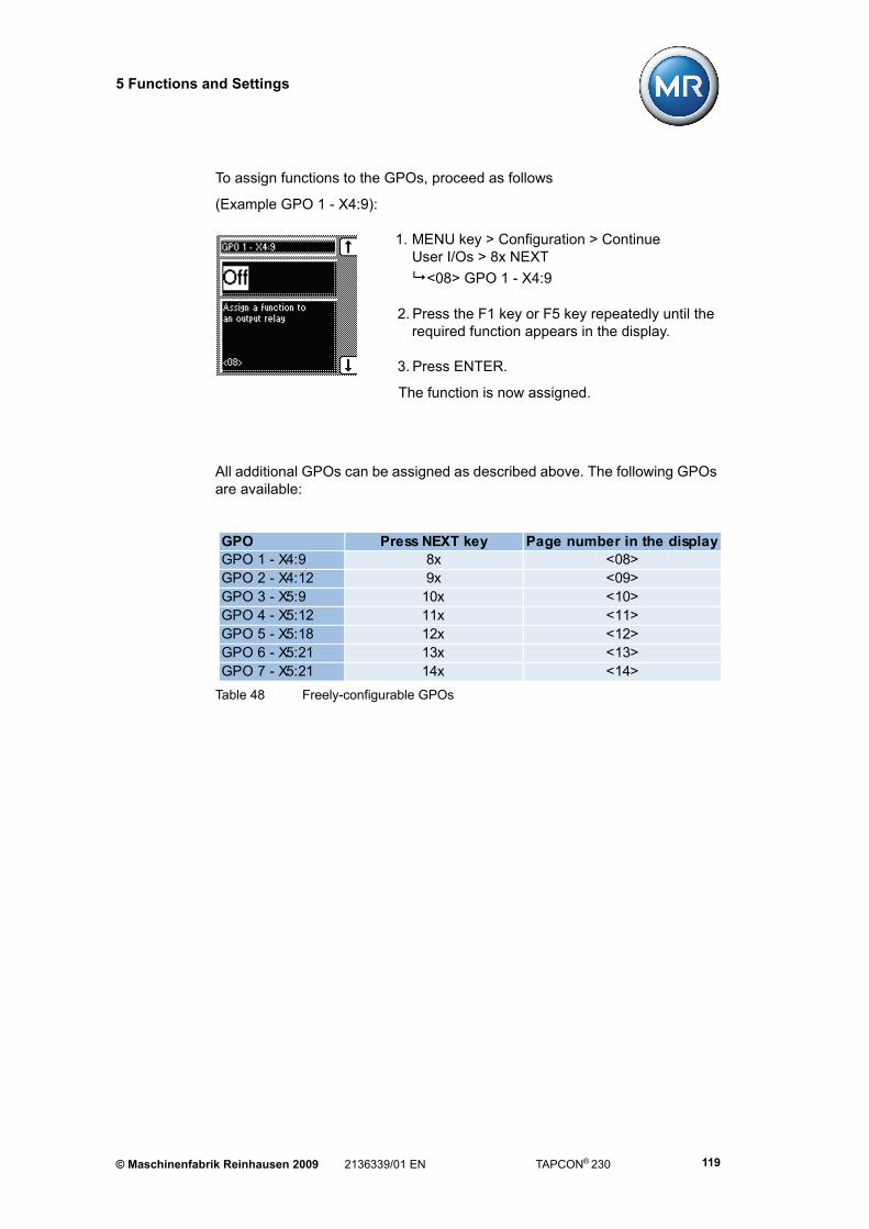
5 Functions and Settings
To assign functions to the GPOs, proceed as follows
(Example GPO 1 - X4:9):
1. MENU key > Configuration > ContinueUser I/Os > 8x NEXT
<08> GPO 1 - X4:9
2. Press the F1 key or F5 key repeatedly until the required function appears in the display.
3. Press ENTER.
The function is now assigned.
All additional GPOs can be assigned as described above. The following GPOs are available:
Table 48 Freely-configurable GPOs
GPO Press NEXT key Page number in the displayGPO 1 - X4:9 8x <08>GPO 2 - X4:12 9x <09>GPO 3 - X5:9 10x <10>GPO 4 - X5:12 11x <11>GPO 5 - X5:18 12x <12>GPO 6 - X5:21 13x <13>GPO 7 - X5:21 14x <14>
© Maschinenfabrik Reinhausen 2009 2136339/01 EN TAPCON® 230 119

5 Functions and Settings
5.5.3 Setting LEDs
The settings in this subgroup can be used to assign an input or function to the free LEDs. If an event occurs, the LED lights up, providing that the relevant function has been set.
To label the LED, the label strip underneath can be removed and labelled indi-vidually (e.g. using transferrable lettering).
MENU key > Configuration > Continue > LED Selection
An overview of the functions which can be assigned is given below. If the cor-responding event occurs, then the assigned LED lights up.
F4F5
F4
TAPCON® 230 2136339/01 EN © Maschinenfabrik Reinhausen 2009120

5 Functions and Settings
The following functions are available for the LEDs:
Table 49 Function options for LEDs
Function options Description of functions1 Off LED deactivated2 GPI 1 Signal issued at GPI 1 input3 GPI 2 Signal issued at GPI 2 input
4 GPI 3 Signal issued at GPI 3 input
5 GPI 4 Signal issued at GPI 4 input
6 GPI 5 Signal issued at GPI 5 input
7 GPI 6 Signal issued at GPI 6 input
8 GPI 7 Signal issued at GPI 7 input
9 GPI 8 Signal issued at GPI 8 input
10 GPO 1 Relay output GPO1 operative
11 GPO 2 Relay output GPO2 operative
12 GPO 3 Relay output GPO3 operative
13 GPO 4 Relay output GPO4 operative
14 GPO 5 Relay output GPO4 operative
15 GPO 6 Relay output GPO5 operative
16 GPO 7 Relay output GPO6 operative
17 Undercurr. Undercurrent detected
18 FailParCtr. Parallel operation error detected
19 MPS tripped Motor protection switch tripped
20 Blocking Control blocked
21 Circ.current Parallel operation using circulating current selected
22 Master Regulator in parallel operation activated
23 Follower Regulator in parallel operation activated
24 Bandwidth < Lower tolerance band exceeded
25 Bandwidth > Upper tolerance band exceeded
26 DVL 1 Voltage level 1 active
27 DVL 2 Voltage level 2 active
28 DVL 3 Voltage level 3 active
29 Funct.Monit. Message "Function Monitoring" active30 Remote REMOTE active
31 Local LOCAL active
32 Auto Automatic mode active
33 Manual Manual mode active
34 Event Event active
© Maschinenfabrik Reinhausen 2009 2136339/01 EN TAPCON® 230 121

5 Functions and Settings
A function can be assigned to an LED if desired. As soon as the assigned event occurs, the selected LED lights up. There is a total of 6 LEDs available which can each be assigned an input or a function.
To assign a function to an LED, proceed as follows (Example: "LED 1"):
1. MENU key > Configuration > Continue > LED selection
<00> LED 1
2. Press the F1 key or F5 key repeatedly until the required function appears in the display.
3. Press ENTER.
The function is now assigned.
All additional LEDs can be assigned as described above. The following LEDs are available:
Table 50 Freely-configurable LEDs
LED Characteristics Press NEXT key Page number in the display
LED 1 Monochromatic – <00>LED 2 Monochromatic 1x <01>LED 3 yellow Dichromatic 2x <02>LED 3 green Dichromatic 3x <03>LED 4 red Dichromatic 4x <04>LED 4 yellow Dichromatic 5x <05>
TAPCON® 230 2136339/01 EN © Maschinenfabrik Reinhausen 2009122

5 Functions and Settings
5.6 Tap position capture
If the tap position is captured using an analog signal, then the analog input (ter-minal strip X7) must be adapted to the signal of the tap position transmitter.
The following tap position transmitters can be used:
• Tap position potentiometer (200 - 2,000 Ohm)
• Or injected current 0/4-20 mA
Adjustment to the existing tap position transmitter must be carried out during commissioning.
MENU key > Configuration > Continue > Continue > Tap Pos. Options
The analog input (terminal strip X7) can be used either for capturing the tap position or for setting the voltage level remotely.
F4
F5F5
F5
F3
© Maschinenfabrik Reinhausen 2009 2136339/01 EN TAPCON® 230 123

5 Functions and Settings
5.6.1 Tap position input options
Six options are available for setting the tap position input:
• Off (no tap position input)
• Current 0/4 - 20 mA
• Resistor contact series
• BCD (see Table 51)
• Gray (see Table 51)
• Binary (see Table 51)
Table 51 Code tables
20 10 8 4 2 1 32 16 8 4 2 11 X X X2 X X X X3 X X X X X4 X X X X5 X X X X X X X6 X X X X X X7 X X X X X X X8 X X X X9 X X X X X X X
10 X X X X X X X11 X X X X X X X X12 X X X X X X13 X X X X X X X X X14 X X X X X X X15 X X X X X X X X16 X X X X X X17 X X X X X X X X X18 X X X X X X X X19 X X X X X X X X X20 X X X X X X X…
Operating position
BCD Gray Binary
TAPCON® 230 2136339/01 EN © Maschinenfabrik Reinhausen 2009124

5 Functions and Settings
To select the tap position input option, proceed as follows:
1. MENU key > Configuration > Continue > Continue > Tap Pos. Options
<00> Tap pos. indication
2. Press the F1 key or F5 key to select the required option.
3. Press ENTER.
The required option for the tap position input is now selected.
5.6.2 Assigning the analog value for the minimum tap position
To configure the analog input, the lower value of the input signal must be spe-cified.
With injected current as the transmitter signal, the values to enter are 0 % in the case of 0 mA and 20 % n the case of 4 mA (see Example inTable 52).
If the transmitter for capturing the tap position is a resistor contact series (poten-tiometer), then 0 % must be always be used.
To assign the minimum tap position to the analog value, proceed as described on the next page:
Table 52 Example for configuring the analog input (min.)
Tap position Current ValueMinimum tap position 1 4 mA 20% (of analog input signal range)
Table 53 Setting range for analog value for minimum tap position
Setting range Step size Factory settings0 % – 100 % 0.1 % 0 %
© Maschinenfabrik Reinhausen 2009 2136339/01 EN TAPCON® 230 125

5 Functions and Settings
1. MENU key > Configuration > Continue > Continue > Tap position > 1x NEXT
<01> Analog Val. Tap Pos. Min
2. Press F4 in order to highlight the position.
The required position is now highlighted and the value can be changed.
3. Press F1 to increase the value or F5 to decrease it.
4. Press ENTER.
The analog value for the minimum tap position is now assigned.
5.6.3 Setting the analog value for the maximum tap position
To configure the analog input, the upper value of the input signal must be spe-cified.
With injected current as the transmitter signal, the values to enter are 0 % in the case of 0 mA and 20 % n the case of 4 mA (see Example in Table 54).
If the transmitter for capturing the tap position is a resistor contact series (poten-tiometer), then 100 % must be always be used.
To set the maximum tap position for the analog value, proceed as described on the next page:
Table 54 Example for configuring the analog input (max.)
Tap position Current ValueMaximum tap position
1920 mA 100% (of analog input signal range)
Table 55 Setting range for analog value for maximum tap position
Setting range Step size Factory settings0 % – 100 % 0.1 % 100 %
TAPCON® 230 2136339/01 EN © Maschinenfabrik Reinhausen 2009126
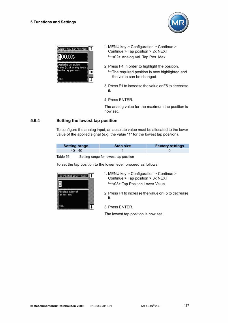
5 Functions and Settings
1. MENU key > Configuration > Continue > Continue > Tap position > 2x NEXT
<02> Analog Val. Tap Pos. Max
2. Press F4 in order to highlight the position.
The required position is now highlighted and the value can be changed.
3. Press F1 to increase the value or F5 to decrease it.
4. Press ENTER.
The analog value for the maximum tap position is now set.
5.6.4 Setting the lowest tap position
To configure the analog input, an absolute value must be allocated to the lower value of the applied signal (e.g. the value "1" for the lowest tap position).
To set the tap position to the lower level, proceed as follows:
1. MENU key > Configuration > Continue > Continue > Tap position > 3x NEXT
<03> Tap Position Lower Value
2. Press F1 to increase the value or F5 to decrease it.
3. Press ENTER.
The lowest tap position is now set.
Table 56 Setting range for lowest tap position
Setting range Step size Factory settings-40 - 40 1 0
© Maschinenfabrik Reinhausen 2009 2136339/01 EN TAPCON® 230 127

5 Functions and Settings
5.6.5 Setting the highest tap position
To configure the analog input, an absolute value must be allocated to the upper value of the applied signal (e.g. the value "25" for the highest tap position).
To set the highest tap position, proceed as follows:
1. MENU key > Configuration > Continue > Continue
> Tap position > 4x NEXT
<04> Tap Position Upper Value
2. Press F1 to increase the value or F5 to decrease it.
3. Press ENTER.
The highest tap position is now set.
Table 57 Setting range for highest tap position
Setting range Step size Factory settings-40 - 40 1 19
TAPCON® 230 2136339/01 EN © Maschinenfabrik Reinhausen 2009128

5 Functions and Settings
5.6.6 Setting the lower tap position blocking limit
If it is necessary to limit the number of tap positions available during operation, a lower tap position blocking limit can be specified. When the minimum defined tap position is reached then tap position blocking is activated. This prevents any further tap change downwards.
To define the lower tap position blocking limit, proceed as follows
1. MENU key > Configuration > Continue > Continue > Tap position > 5x NEXT
<05> Blocking lower Tap
2. Press F1 to increase the value or F5 to decrease it.
3. Press F4 to highlight a digit (for values >10).
The required position is now highlighted and the value can be changed.
4. Press ENTER.
The lower tap position blocking limit is now set.
Figure 21 Range of tap positions
1 Highest tap position
2 Limited range of tap positions
3 Lowest tap position
Table 58 Setting range for lower tap position blocking limit
Setting range Step size Factory settings-128 - 128 1 0
© Maschinenfabrik Reinhausen 2009 2136339/01 EN TAPCON® 230 129
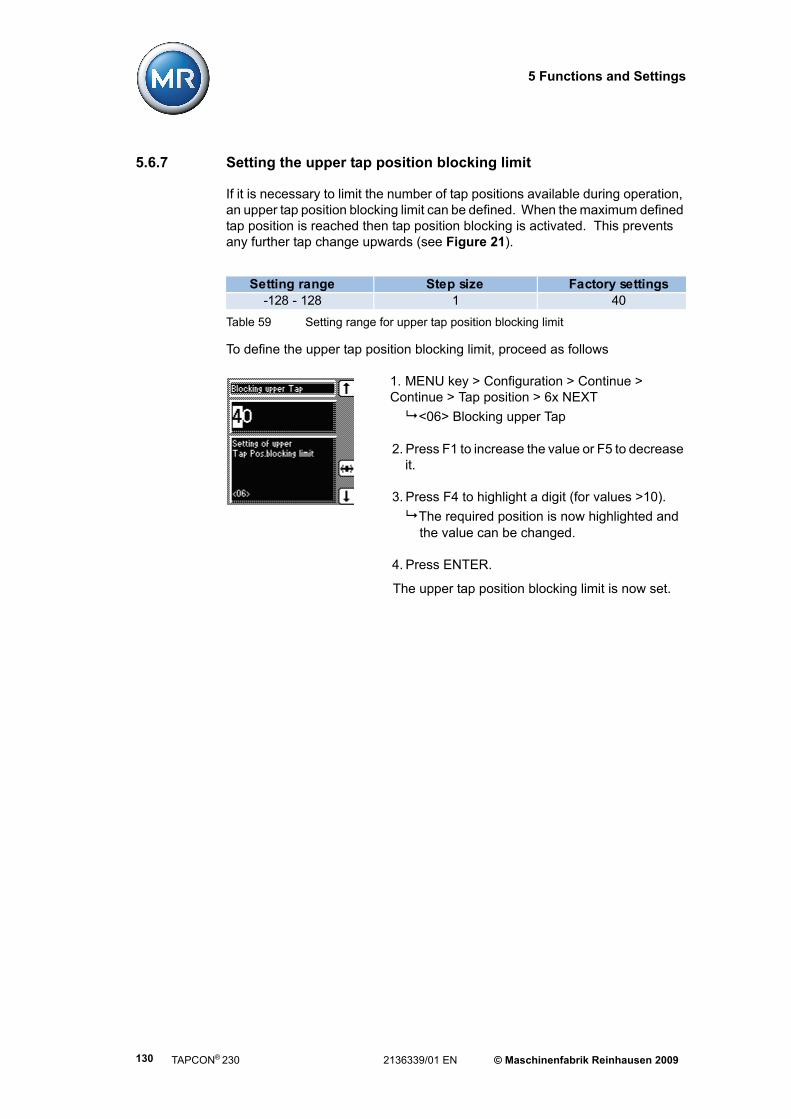
5 Functions and Settings
5.6.7 Setting the upper tap position blocking limit
If it is necessary to limit the number of tap positions available during operation, an upper tap position blocking limit can be defined. When the maximum defined tap position is reached then tap position blocking is activated. This prevents any further tap change upwards (see Figure 21).
To define the upper tap position blocking limit, proceed as follows
1. MENU key > Configuration > Continue > Continue > Tap position > 6x NEXT
<06> Blocking upper Tap
2. Press F1 to increase the value or F5 to decrease it.
3. Press F4 to highlight a digit (for values >10).
The required position is now highlighted and the value can be changed.
4. Press ENTER.
The upper tap position blocking limit is now set.
Table 59 Setting range for upper tap position blocking limit
Setting range Step size Factory settings-128 - 128 1 40
TAPCON® 230 2136339/01 EN © Maschinenfabrik Reinhausen 2009130
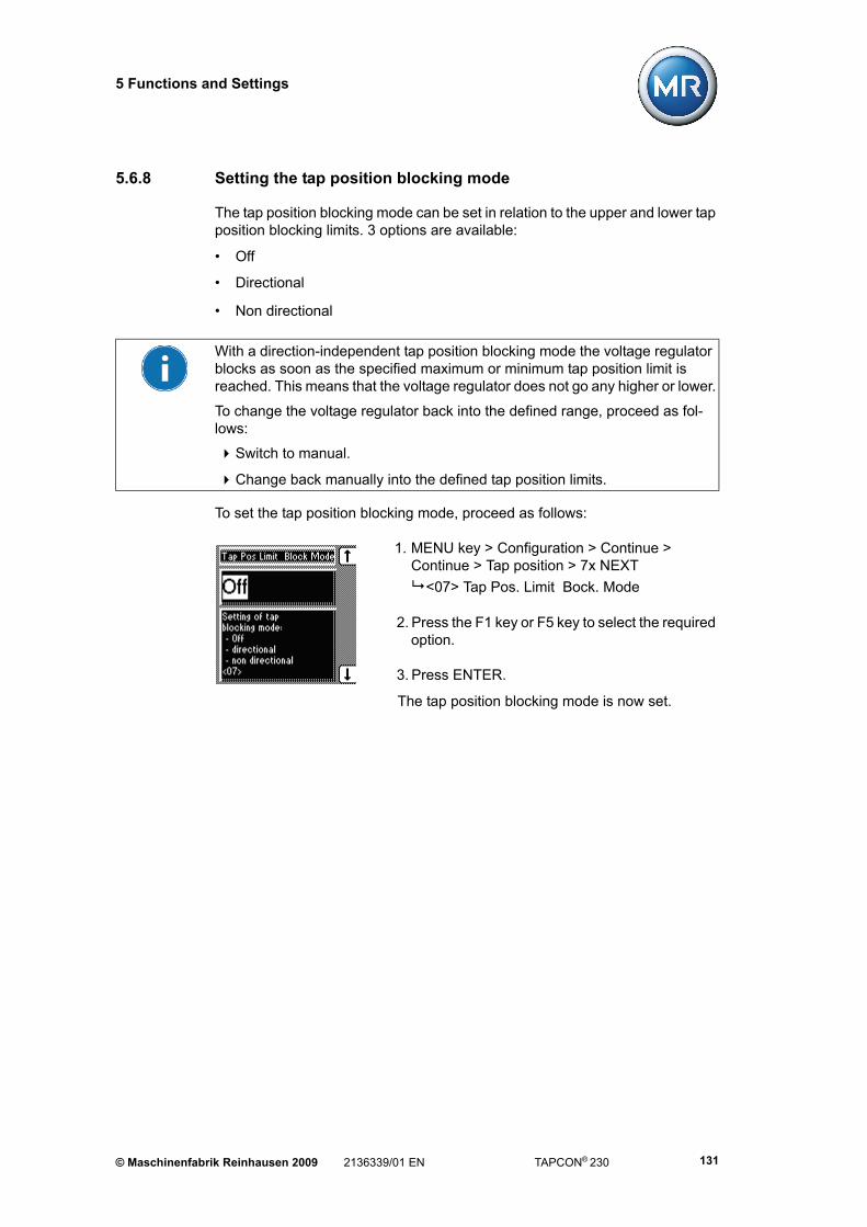
5 Functions and Settings
5.6.8 Setting the tap position blocking mode
The tap position blocking mode can be set in relation to the upper and lower tap position blocking limits. 3 options are available:
• Off
• Directional
• Non directional
To set the tap position blocking mode, proceed as follows:
1. MENU key > Configuration > Continue > Continue > Tap position > 7x NEXT
<07> Tap Pos. Limit Bock. Mode
2. Press the F1 key or F5 key to select the required option.
3. Press ENTER.
The tap position blocking mode is now set.
With a direction-independent tap position blocking mode the voltage regulator blocks as soon as the specified maximum or minimum tap position limit is reached. This means that the voltage regulator does not go any higher or lower.
To change the voltage regulator back into the defined range, proceed as fol-lows:
Switch to manual.
Change back manually into the defined tap position limits.
© Maschinenfabrik Reinhausen 2009 2136339/01 EN TAPCON® 230 131
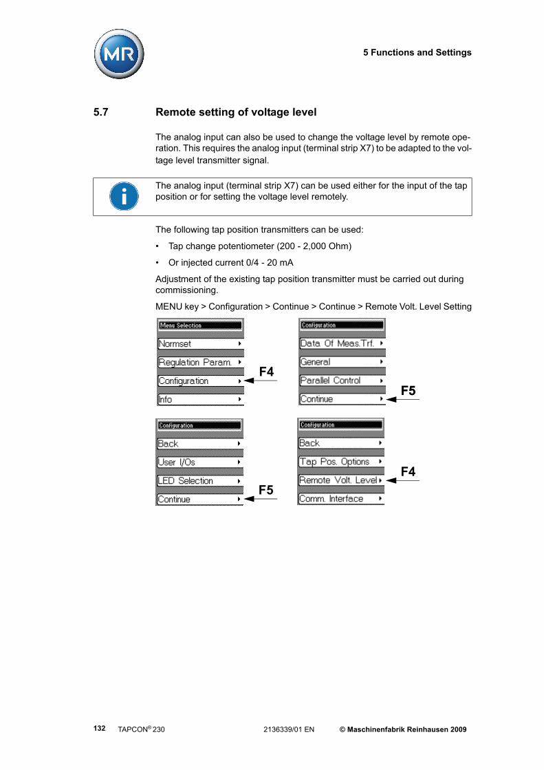
5 Functions and Settings
5.7 Remote setting of voltage level
The analog input can also be used to change the voltage level by remote ope-ration. This requires the analog input (terminal strip X7) to be adapted to the vol-tage level transmitter signal.
The following tap position transmitters can be used:
• Tap change potentiometer (200 - 2,000 Ohm)
• Or injected current 0/4 - 20 mA
Adjustment of the existing tap position transmitter must be carried out during commissioning.
MENU key > Configuration > Continue > Continue > Remote Volt. Level Setting
The analog input (terminal strip X7) can be used either for the input of the tap position or for setting the voltage level remotely.
F4
F5F5
F5
F4
TAPCON® 230 2136339/01 EN © Maschinenfabrik Reinhausen 2009132

5 Functions and Settings
5.7.1 Remote voltage level setting options
There are 3 options for setting the voltage level remotely:
• Off (no remote setting of voltage level)
• Current of 0/4 - 20 mA
• Resistor contact series
Proceed as follows:
1. MENU key > Configuration > Continue > Continue > Remote Volt. Level Setting
<00> Remote Volt. Level Setting
2. Press the F1 key or F5 key to select the required option.
3. Press ENTER.
The method of setting the remote voltage level is now selected.
© Maschinenfabrik Reinhausen 2009 2136339/01 EN TAPCON® 230 133

5 Functions and Settings
5.7.2 Setting the analog value for the minimum voltage level
To configure the analog input, the lower value of the input signal must be spe-cified.
With injected current as the transmitter signal, the values to enter are 0 % in the case of 0 mA and 20 % n the case of 4 mA (see Example inTable 60).
If the transmitter for capturing the tap position is a resistor contact series (poten-tiometer), then 20 % must be always be used.
To set the minimum analog voltage level, proceed as follows:
1. MENU key > Configuration > Continue > Continue > Remote Volt. Level Setting. > 1x NEXT
<01> Analog Value % Volt. Level Min
2. Press F4 in order to highlight the position.
The required position is now highlighted and the value can be changed.
3. Press F1 to increase the value or F5 to decrease it.
4. Press ENTER.
The minimum analog voltage level is now set.
Table 60 Example for configuring the analog input (min.)
Tap position Current Valuemin. Set value 90 V 4 mA 20% (of analog input signal range)
Table 61 Setting range for analog value for minimum voltage level
Setting range Step size Factory settings0 % – 100 % 0.1 % 0 %
TAPCON® 230 2136339/01 EN © Maschinenfabrik Reinhausen 2009134

5 Functions and Settings
5.7.3 Setting the analog value for the maximum voltage level
To configure the analog input, the maximum value of the input signal must be specified.
With injected current as the transmitter signal, the values to enter are 0 % in the case of 0 mA and 20 % n the case of 4 mA.
If the transmitter for the remote voltage level setting is a resistor contact series (potentiometer), then 20 % must be always be used (see Table 62).
To set the maximum analog voltage level, proceed as follows:
1. MENU key > Configuration > Continue > Continue
> Remote Volt. Level Setting. > 2x NEXT
<02> Analog Value % Volt. Level Max
2. Press F4 in order to highlight the position.
The required position is now highlighted and the value can be changed.
3. Press F1 to increase the value or F5 to decrease it.
4. Press ENTER.
The maximum analog voltage level is now set.
Table 62 Example for configuring the analog input (max.)
Tap position Current ValueMax. voltage level 110 V 20 mA 100% (of analog input signal range)
Table 63 Setting range for analog value for maximum voltage level
Setting range Step size Factory settings0% - 100% 0.1% 100%
© Maschinenfabrik Reinhausen 2009 2136339/01 EN TAPCON® 230 135
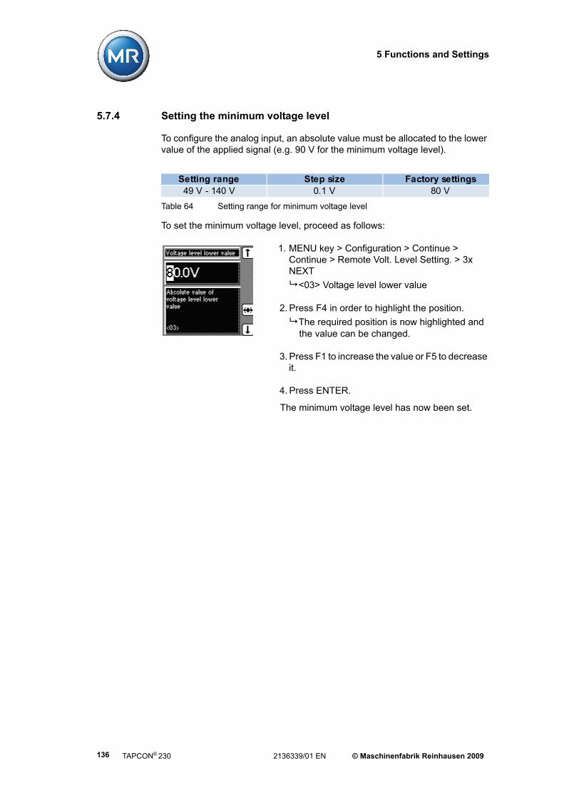
5 Functions and Settings
5.7.4 Setting the minimum voltage level
To configure the analog input, an absolute value must be allocated to the lower value of the applied signal (e.g. 90 V for the minimum voltage level).
To set the minimum voltage level, proceed as follows:
1. MENU key > Configuration > Continue > Continue > Remote Volt. Level Setting. > 3x NEXT
<03> Voltage level lower value
2. Press F4 in order to highlight the position.
The required position is now highlighted and the value can be changed.
3. Press F1 to increase the value or F5 to decrease it.
4. Press ENTER.
The minimum voltage level has now been set.
Table 64 Setting range for minimum voltage level
Setting range Step size Factory settings49 V - 140 V 0.1 V 80 V
TAPCON® 230 2136339/01 EN © Maschinenfabrik Reinhausen 2009136

5 Functions and Settings
5.7.5 Setting the maximum voltage level
To configure the analog input, an absolute value must be allocated to the upper value of the applied signal (e.g. 110 V for the maximum voltage level).
To set the maximum voltage level, proceed as follows:
1. MENU key > Configuration > Continue > Continue > Remote Volt. Level Setting. > 4x NEXT
<04> Voltage level upper value
2. Press F4 in order to highlight the position.
The required position is now highlighted and the value can be changed.
3. Press F1 to increase the value or F5 to decrease it.
4. Press ENTER.
The voltage level upper value is now set.
Table 65 Setting range for maximum voltage level
Setting range Step size Factory settings49 V - 140 V 0.1 V 140 V
© Maschinenfabrik Reinhausen 2009 2136339/01 EN TAPCON® 230 137

5 Functions and Settings
5.8 Communication interface (only TAPCON® 230 expert)
The TAPCON® 230 expert voltage regulator has additional communication inter-faces.
MENU key > Configuration > Continue > Continue > Comm. Interface
The TAPCON® 230 expert has various PCB connections to guarantee commu-nication with the voltage regulator. The voltage regulator is equipped with the following interfaces:
• Serial interface RS232
• RS485
• Ethernet
• Fibre-optic cable
Setting the PCB connections and each of their functions is described in more detail in the following sections:
F4
F5F5
F5 F5
TAPCON® 230 2136339/01 EN © Maschinenfabrik Reinhausen 2009138

5 Functions and Settings
5.8.1 Selecting the communication protocol
This enables the required communication protocol to be activated. The fol-lowing options are available:
• TAPCON-trol® (visualisation software)
• DNP3
• Modbus ASCII
• Modbus RTU
• IEC60870-5-101
• IEC60870-5-103
1. MENU key > Configuration > Continue > Continue > Comm. Interface
<00> Communication Protocol
2. Press the F1 key or F5 key to select the required option.
3. Press ENTER.
The communication protocol is now set.
Only one communication protocol can be selected. All remaining protocols remain disabled. Simultaneous use of several communication protocols is not possible.
© Maschinenfabrik Reinhausen 2009 2136339/01 EN TAPCON® 230 139

5 Functions and Settings
5.8.2 Selecting the communication port
This enables the physical interface to be activated. The following options are available:
• RS232
• RS485
• Ethernet
• OWG
To set the communication port, proceed as follows:
1. MENU key > Configuration > Continue > Continue > Comm. Interface. > 1x NEXT
<01> Communication Port
2. Press the F1 key or F5 key to select the required option.
3. Press ENTER.
The communication port is now set.
Only one communication port can be selected. All remaining ports remain disa-bled. Simultaneous use of several communication ports is not possible.
TAPCON® 230 2136339/01 EN © Maschinenfabrik Reinhausen 2009140

5 Functions and Settings
5.8.3 Selecting the communication baud rate
This enables selection of the required transfer speed for the communication interface. The following transfer speeds are available:
• 9.6 kilobaud
• 19.2 kilobaud
• 38.4 kilobaud
• 57.6 kilobaud
To set the communication interface baud rate, proceed as follows:
1. MENU key > Configuration > Continue > Continue > Comm. Interface.> 2x NEXT
<02> Baud Rate Communication
2. Press the F1 key or F5 key to select the required baud rate.
3. Press ENTER.
The baud rate is now set.
The baud rate of 57.6 kBd is only active for communication interfaces RS232, RS485 and OWG.
A baud rate of 57.6 kBd cannot be used for Ethernet.
© Maschinenfabrik Reinhausen 2009 2136339/01 EN TAPCON® 230 141

5 Functions and Settings
5.8.4 Obtaining the network address
If the voltage regulator is equipped with an Ethernet module, then the TAPCON® 230 expert must be assigned a valid network address (IPv4).
To assign the network address, proceed as follows:
1. MENU key > Configuration > Continue > Continue > Comm. Interface.> 3x NEXT
<03> IP address
2. Press F4 in order to highlight the position.
The required position is now highlighted and the value can be changed.
3. Press F1 to increase the value or F5 to decrease it.
4. Press ENTER.
The network address for the TAPCON® 230 expert is now assigned.
Table 66 Setting range for network address
Setting range Step size Factory settings0 – 255 1 0.0.0.0
TAPCON® 230 2136339/01 EN © Maschinenfabrik Reinhausen 2009142

5 Functions and Settings
5.8.5 Assigning the TCP port
If the voltage regulator is equipped with an Ethernet module, then the TAPCON® 230 expert must be assigned a valid network address (IPv4).
To set the TCP port, proceed as follows:
1. MENU key > Configuration > Continue > Continue > Comm. Interface. > 4x NEXT
<04> TCP Port
2. Press F4 in order to highlight the position.
The required position is now highlighted and the value can be changed.
3. Press F1 to increase the value or F5 to decrease it.
4. Press ENTER.
The TCP port is now set.
Table 67 Setting range for TCP port
Setting range Step size Factory settings0 – 255 1 0.0.0.0
© Maschinenfabrik Reinhausen 2009 2136339/01 EN TAPCON® 230 143

5 Functions and Settings
5.8.6 Assigning the fibre-optic cable polarity
If the voltage regulator is equipped with an OWG module, a communication link can be established using a fibre-optic cable.
The relevant physical signals can be assigned to the logic information "0" and "1" (see Table 68).
To assign the fibre-optic cable, proceed as follows:
1. MENU key > Configuration > Continue > Continue > Comm. Interface.> 5x NEXT
<05> Optical Fibre Light On / Off
2. Press the F1 or F5 key to activate (On) or deactivate (Off) the fibre-optic cable signal inversion.
3. Press ENTER.
The fibre-optic cable polarity is now set.
Table 68 Setting range for TCP port
Parameter Logic 1 Logic 0ON Light on Light off
OFF Light off Light on
TAPCON® 230 2136339/01 EN © Maschinenfabrik Reinhausen 2009144

5 Functions and Settings
5.8.7 Setting the SCADA address
This enables a valid SCADA address to be set for the chosen control system protocol. The voltage regulator communication address must be specified when connecting to the control system.
To enter the SCADA address, proceed as follows:
1. MENU key > Configuration > Continue > Continue > Comm. Interface.> 6x NEXT
<06> Local SCADA Address
2. Press F1 to change the first digit.
If you wish to enter a multidigit sequence, continueto step 3. If you do not wish to enter additionaldigits, proceed to step 7:
3. Press the F1 key repeatedly (> 9) until a further digit position appears.
4.Press F4 in order to highlight the digit position.
The required digit is highlighted and can be changed.
5. Press F1 or F5 to change the digit.
6. Repeat steps 3 to 5 until all required digits have been entered.
7. Press ENTER.
The SCADA address is now set.
Table 69 Setting range for SCADA address
Setting range Step size Factory settings0 – 9999 1 0
© Maschinenfabrik Reinhausen 2009 2136339/01 EN TAPCON® 230 145

5 Functions and Settings
5.8.8 Entering the SCADA master address
The address for the master station can be entered when using the DNP3. The control data are automatically sent to this address i.e. the master station when restarting the voltage regulator.
To enter the SCADA master address, proceed as follows:
1. MENU key > Configuration > Continue > Continue > Comm. Interface.> 7x NEXT
<07> SCADA Master Address
2. Press F1 to change the first digit.
If you wish to enter a multidigit sequence, continueto step 3. If you do not wish to enter additionaldigits, proceed to step 7:
3. Press the F1 key repeatedly (> 9) until a further digit position appears.
4.Press F4 in order to highlight the digit position.
The required digit is highlighted and can be changed.
5. Press F1 or F5 to change the digit.
6. Repeat steps 3 to 5 until all required digits have been entered.
7. Press ENTER.
The SCADA master address is now entered.
Table 70 Setting range for SCADA master address
Setting range Step size Factory settings0 – 9,999 1 0
TAPCON® 230 2136339/01 EN © Maschinenfabrik Reinhausen 2009146

5 Functions and Settings
5.8.9 Enabling unsolicited messages
If DNP3 has been selected, then automatic data transmission via the voltage regulator can be enabled using this parameter. The criterion for automatic data transmission is the occurrence of a relevant event.
To have the voltage regulator send automatic control data, enable data trans-mission by selecting "On".
To enable automatic messages, proceed as follows:
1. MENU key > Configuration > Continue > Continue > Comm. Interface.> 8x NEXT
<08> Unsolicited messages
2. Press the F1 or F5 key to enable (On) or block (Off) automatic messages.
3. Press ENTER.
Automatic messages are enabled/blocked.
The voltage regulator must be restarted after changing this setting.
© Maschinenfabrik Reinhausen 2009 2136339/01 EN TAPCON® 230 147

5 Functions and Settings
5.8.10 Setting the number of unsolicited retries
The voltage regulator sends a request to the master to enable data transfer if events for automatic data transmission in the voltage regulator occur. If the vol-tage regulator does not receive this permission from the master (due to trans-mission errors, for example) this parameter defines the maximum number of repeated send attempts.
If the value "0" is set, then an infinite number of send attempts is carried out.
To set the number of retries for automatic messages, proceed as follows:
1. MENU key > Configuration > Continue > Continue > Comm. Interface.> 9x NEXT
<09> Unsolicited Retries
2. Press the F1 or F5 keys to activate (On) or deactivate (Off) automatic retries.
3. Press ENTER.
The number of retires for automatic messages is now set.
Table 71 Setting range for automatic retries
The voltage regulator must be restarted after changing this setting.
Setting range Step size Factory settings0 – 100 1 3
TAPCON® 230 2136339/01 EN © Maschinenfabrik Reinhausen 2009148

5 Functions and Settings
5.8.11 Setting application timeout confirmation
This parameter is used to set the time interval of retries for automatic messa-ges. If the voltage regulator does not receive permission for data transmission, further requests can be sent to the master at regular intervals of e.g. 3 seconds, if this has been set.
The number of requests sent is dependent on the set number of retries for auto-matic messages. These are described in Section 5.8.10.
To set the timeout for application confirmation, proceed as follows:
1. MENU key > Configuration > Continue > Continue > Comm. Interface.> 10x NEXT
<10> App. Confirm Timeout
2. Press F1 to increase the value or F5 to decrease it.
3. Press ENTER.
The timeout for application confirmation is now set.
Table 72 Setting range for application timeout confirmation
Setting range Step size Factory settings1 s – 60 s 1 s 5 s
© Maschinenfabrik Reinhausen 2009 2136339/01 EN TAPCON® 230 149
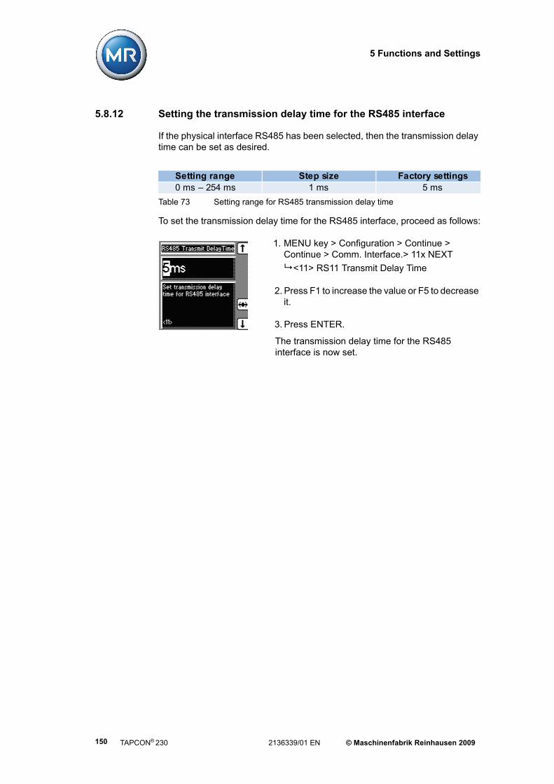
5 Functions and Settings
5.8.12 Setting the transmission delay time for the RS485 interface
If the physical interface RS485 has been selected, then the transmission delay time can be set as desired.
To set the transmission delay time for the RS485 interface, proceed as follows:
1. MENU key > Configuration > Continue > Continue > Comm. Interface.> 11x NEXT
<11> RS11 Transmit Delay Time
2. Press F1 to increase the value or F5 to decrease it.
3. Press ENTER.
The transmission delay time for the RS485 interface is now set.
Table 73 Setting range for RS485 transmission delay time
Setting range Step size Factory settings0 ms – 254 ms 1 ms 5 ms
TAPCON® 230 2136339/01 EN © Maschinenfabrik Reinhausen 2009150

5 Functions and Settings
5.9 Info
This menu item displays general information on the voltage regulator. In addi-tion, calibration of the resistor contact series can be carried out on the analog input (terminal strip X7) (see Section 5.10):
• Measured values
• Calculated values
• Functional reliability of the LEDs (LED test)
• MIO card digital inputs (terminals X4:13 - X4:24)
• MIO card digital outputs (terminals X3:3 - X4:12)
• PIO card digital inputs (terminals X6:1 - X6:15)
• PIO card digital outputs (terminals X5:3 - X5:24)
• Parallel mode
• Data on CAN bus
• Peak memory
• CI card information
• Default Parameter
• Memory overview
• Event overview
To make things easier to find, subgroups are formed from related information.
MENU key > Info
Each of the information displays is described in the following sections.
F5
© Maschinenfabrik Reinhausen 2009 2136339/01 EN TAPCON® 230 151

5 Functions and Settings
5.9.1 Displaying the Info Screen
Information on the device can be viewed here. The following information is dis-played:
• Device model
• Firmware version number
• Serial number
• RAM - working memory
• Additional cards
To view the information on the device, proceed as described below:
MENU key > Info
<00> Info
TAPCON® 230 2136339/01 EN © Maschinenfabrik Reinhausen 2009152

5 Functions and Settings
5.9.2 Displaying measurement values
The current measurement values can be viewed here. The following measure-ment values can be displayed:
• Voltage V in V and kV
• Current I in % and A
• Phase
• Pmeas
• f (frequency)
For "Phase" measurement, the actual measured phase (in Figure: -0.6°) is given on the left. The phase converted by the measured transformer circuit (here in Figure = 359.3°) is shown on the right.
To display the measurement values, proceed as follows:
MENU key > Info > 1x NEXT
<01> Measured values
The values to the right (see figure below) of the voltage, current and power are only displayed if the transformer data have been entered previously.
© Maschinenfabrik Reinhausen 2009 2136339/01 EN TAPCON® 230 153

5 Functions and Settings
5.9.3 Display calculated values
The calculated values can be viewed here. Values displayed:
• I active power in A
• I reactive power in A
• S in MVA
• Q in Mvar
• CosPhi
• Op. Cnt. (Operation counter)
To display the calculated values, proceed as follows:
MENU key > Info > 2x NEXT
<02> Calculated values
The values on the right (see Figure below) are only displayed if the transformer data have been entered previously.
TAPCON® 230 2136339/01 EN © Maschinenfabrik Reinhausen 2009154

5 Functions and Settings
5.9.4 Carry out LED test
An LED function test can be carried out based on the information displayed. This checks whether all the LEDs are functioning
To carry out the LED test, proceed as follows:
1. MENU key > Info > 3x NEXT
<03> LED test
2. To carry out the function test, press any F key for the required LED (see Table 74).
Table 74 Selecting the LEDs for tests
Key LED number LEDF1 LED 1 AUTOF2 LED 2 MANUALF3 LED 3 LOWERF4 LED 4 RAISEF5 LED 5 > I
ENTER All LEDs All LEDs
© Maschinenfabrik Reinhausen 2009 2136339/01 EN TAPCON® 230 155

5 Functions and Settings
5.9.5 Display MIO card digital inputs
The "MIO card digital Inputs" displays the status of each of the optocoupler inputs. As soon as a continuous signal is present at the input, it is shown in the display with a "1". "0" indicates no signal at the input.
To display "MIO Inputs", proceed as follows:
MENU key > Info > 4x NEXT
<04> MIO-Card Digital Inputs
5.9.6 Display MIO card digital inputs
The "MIO card digital outputs" displays the status of each of the relays. As soon as a relay is activated, it is shown as a "1" in the display. With "0", the relay is not activated.
To display "MIO Outputs", proceed as follows:
MENU key > Info > 5x NEXT
<05> MIO-Card Digital Outputs
TAPCON® 230 2136339/01 EN © Maschinenfabrik Reinhausen 2009156

5 Functions and Settings
5.9.7 Display PIO card digital inputs
The "PIO card digital inputs" displays the status of each of the optocoupler inputs. As soon as a continuous signal is present at the input, it is shown in the display with a "1". "0" indicates no signal at the input.
To display "PIO card digital inputs", proceed as follows:
MENU key > Info > 6x NEXT
<06> PIO-Card Digital Inputs
5.9.8 Display PIO card digital outputs
The "PIO card digital outputs" displays the status of each of the relays. As soon as a relay is activated, it is shown as a "1" in the display. With "0", the relay is not activated.
To display "PIO card digital inputs", proceed as follows:
MENU key > Info > 7x NEXT
<07> PIO-Card Digtial Outputs
© Maschinenfabrik Reinhausen 2009 2136339/01 EN TAPCON® 230 157

5 Functions and Settings
5.9.9 Displaying parallel operation
This display indicates the control number for parallel operation (= CAN address) and the number of voltage regulators which are currently operating in parallel.
To display "Parallel operation", proceed as follows:
MENU key > Info > 9x NEXT
<09> Parallel Operation
5.9.10 Displaying data on CAN bus
To display the "CAN bus", proceed as follows:
MENU key > Info > 10x NEXT
<10> Data On CAN-Bus
TAPCON® 230 2136339/01 EN © Maschinenfabrik Reinhausen 2009158

5 Functions and Settings
5.9.11 Displaying peak memory
This screen indicates whether the parameter settings are all correctly stored after restarting the voltage regulator or after transferring a parameter setting.
To display "Peak memory", proceed as follows:
MENU key > Info > 11x NEXT
<11> Peak memory
This information can be reset if required:
Press the F3 and F4 keys simultaneously for about 1 second.
All values are now set to default.
5.9.12 CI card SCADA Information
To display the "CI card SCADA information", proceed as follows:
MENU key > Info > 12x NEXT
<12> CI card SCADA Information
This information can be reset if required:
Press the F3 and F4 keys simultaneously for about 1 second.
All values are now set to default.
© Maschinenfabrik Reinhausen 2009 2136339/01 EN TAPCON® 230 159
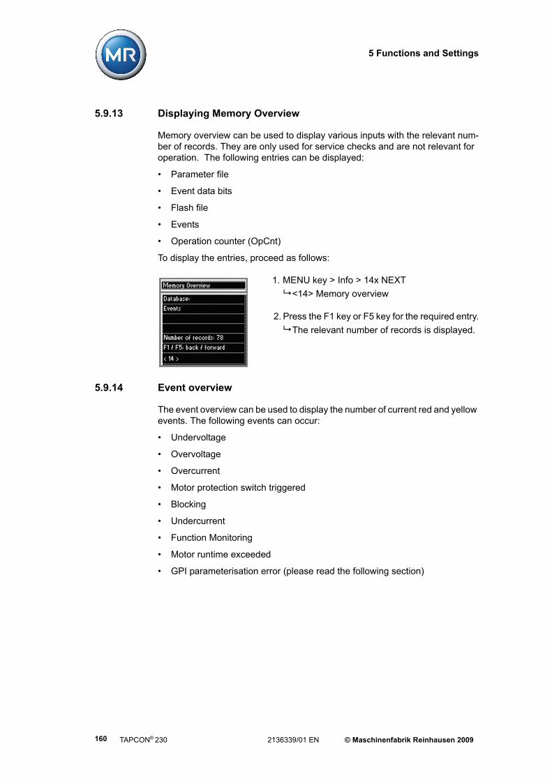
5 Functions and Settings
5.9.13 Displaying Memory Overview
Memory overview can be used to display various inputs with the relevant num-ber of records. They are only used for service checks and are not relevant for operation. The following entries can be displayed:
• Parameter file
• Event data bits
• Flash file
• Events
• Operation counter (OpCnt)
To display the entries, proceed as follows:
1. MENU key > Info > 14x NEXT
<14> Memory overview
2. Press the F1 key or F5 key for the required entry.
The relevant number of records is displayed.
5.9.14 Event overview
The event overview can be used to display the number of current red and yellow events. The following events can occur:
• Undervoltage
• Overvoltage
• Overcurrent
• Motor protection switch triggered
• Blocking
• Undercurrent
• Function Monitoring
• Motor runtime exceeded
• GPI parameterisation error (please read the following section)
TAPCON® 230 2136339/01 EN © Maschinenfabrik Reinhausen 2009160

5 Functions and Settings
The "GPI parameterisation error" event occurs if multiple inputs have been parameterised with the same function. If this event occurs, check all GPIs for correct function assignment and correct if necessary. Make sure that only one function is parameterised on one GPI.
To view the event overview, proceed as follows:
MENU key > Info > 15x NEXT
<15> Event overview
© Maschinenfabrik Reinhausen 2009 2136339/01 EN TAPCON® 230 161
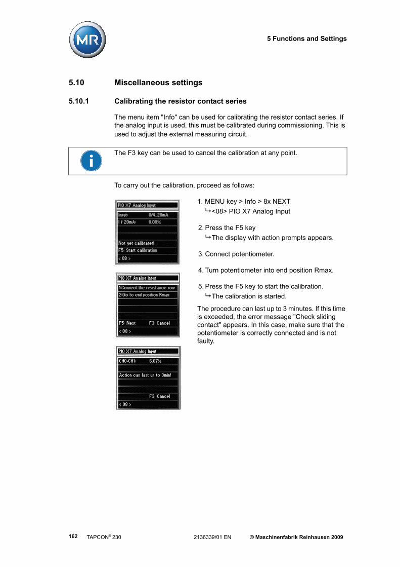
5 Functions and Settings
5.10 Miscellaneous settings
5.10.1 Calibrating the resistor contact series
The menu item "Info" can be used for calibrating the resistor contact series. If the analog input is used, this must be calibrated during commissioning. This is used to adjust the external measuring circuit.
To carry out the calibration, proceed as follows:
1. MENU key > Info > 8x NEXT
<08> PIO X7 Analog Input
2. Press the F5 key
The display with action prompts appears.
3. Connect potentiometer.
4. Turn potentiometer into end position Rmax.
5. Press the F5 key to start the calibration.
The calibration is started.
The procedure can last up to 3 minutes. If this time is exceeded, the error message "Check sliding contact" appears. In this case, make sure that the potentiometer is correctly connected and is not faulty.
The F3 key can be used to cancel the calibration at any point.
TAPCON® 230 2136339/01 EN © Maschinenfabrik Reinhausen 2009162

5 Functions and Settings
5.10.2 Resetting default parameters
"Default Parameter" resets the settings to the factory settings.
To reset the parameters, proceed as follows:
1. Menu > Info > 13x NEXT
<13> Default Parameters
2. Press the F3 key and ENTER simultaneously.
"Default parameter active" is displayed.
All parameters have now been reset to the factory settings.
Resetting the parameters to the factory settings permanently deletes your parameters. The language is reset to the original (English).
© Maschinenfabrik Reinhausen 2009 2136339/01 EN TAPCON® 230 163

5 Functions and Settings
5.11 Summary of setting ranges
lwert 1/2/3 49 V...140 V0 kV...9999 kV
999,9 kV 99,99 kV
0,1 V1 kV
0,1 kV0,01 kV
100 V1 kV
ndbreite 0,5 %...9 % 0,01 % 2 %rzögerungszeit T1 0 s...600 s 1 s 40 srzögerungszeit T2 1 s...10 s 0,1 s 10 sUnterspannungsblockierung 60 %...100 %
vom Sollwert1 % 90 %
Unterspannungsverzögerung 0 s...20 s 0,1 s 10 sÜberspannungsblockierung 100 %...140 %
vom Sollwert1 % 110 %
Überstromblockierung 50 %...210 % 1 % 110 %Unterstromblockierung 0 %...210 % 1 % 0 %mscher Spannungsabfall Ur -25 V... 25 V 0,1 V 0 Vuktiver Spannungsabfall Ux -25 V... 25 V 0,1 V 0 Vompensation annungserhöhung)
0 %...15 %vom Sollwert
0,1 % 0 %
ompensation (ΔU Limit) 0 %...15 %vom Sollwert
0,1 % 0 %
ndlerprimärspannung 0 kV...9999 kV 999,9 kV 99,99 kV
1 kV0,1 kV
0,01 kV0 kV
ndlersekundärspannung 57 V...123 V 0,1 V 100 Vndlerprimärstrom 0 A...9.999 A 1 A 0 A-Schaltimpulsdauer 0 s...10 s 0,1 s 1,5 s
haltungszähler 0…99.999.999 1 0torlaufzeit 0 s...30 s 0,1 s 0 s
Setting range Step size Factory settingsVoltage level 1/2/3 49 V – 140 V
0 kV – 9999 kV 999.9 kV 99.99 kV
0.1 V1 kV
0.1 kV0,01 kV
100 V1 kV
Bandwidth 0.5 % – 9 % 0,01 % 2 %Delay time T1 0 s – 600 s 1 s 40 sDelay time T2 1 s – 10 s 0.1 s 10 sV< undervoltage blocking 60 % – 100 %
vom Sollwert1 % 90 %
V< undervoltage delay 0 s – 20 s 0.1 s 10 sV> overvoltage blocking 100 % – 140 %
vom Sollwert1 % 110 %
I> overcurrent blocking 50 % – 210 % 1 % 110 %I< undercurrent blocking 0 % – 210 % 1 % 0 %Ohmic voltage drop Ur -25 V – 25 V 0.1 V 0 VInductive voltage drop Ux -25 V – 25 V 0.1 V 0 VZ compensation (voltage rise) 0 % – 15 %
vom Sollwert0.1 % 0 %
Z compensation (ΔV limit) 0 % – 15 %vom Sollwert
0.1 % 0 %
Primary transformer voltage 0 kV – 9999 kV 999.9 kV 99.99 kV
1 kV0.1 kV
0.01 kV0 kV
Secondary transformer voltage 57 V – 123 V 0.1 V 100 VPrimary transformer current 0 A...9,999 A 1 A 0 AR/L switching pulse time 0 s – 10 s 0.1 s 1.5 sSchaltungszähler 0 – 99,999,999 1 0Motor runtime 0 s – 30 s 0.1 s 0 s
TAPCON® 230 2136339/01 EN © Maschinenfabrik Reinhausen 2009164

5 Functions and Settings
Table 75 Summary of all setting ranges TAPCON® 230
Table 76 Summary of additional setting ranges TAPCON® 230 expert
Setting range Step size Factory settingsCirculating reactive current sensitivity
0% – 100% 1% 0.0%
Circulating reactive current blocking
0.5 % – 40 % 1 % 20 %
Delay time for parallel mode signal
1 s – 99 s 1 s 10 s
Max. tap difference 0 – 4 1 1Analog value of minimum tap position
0 % – 100 % 0.1 % 0 %
Analog value of maximum tap position
0 % – 100 % 0.1 % 100 %
Tap position (lowest) -40 – 40 1 0Tap position (highest) -40 – 40 1 19Tap position blocking limit (lowest)
-40 – 128 1 0
Tap position blocking limit (highest)
-40 – 128 1 40
Analog value for minimum voltage level
0% – 100 % 0.1 % 0 %
Analog value for maximum 0 % – 100% 0.1 % 100 %Minimum voltage level 49 V – 140 V 0.1 V 80 VMaximum voltage level 49 V – 140 V 0.1 V 140 V
Setting range Step size Factory settingsNetwork address 0 – 255 1 0.0.0.0TCP Port 0 – 255 1 0.0.0.0SCADA address 0 – 99,999,999 1 0SCADA master 0 – 9999 1 0Automatic retries 0 – 100 1 3Application timeout confirmation
1 s – 60 s 1 s 5 s
RS485 send delay time 0 ms – 254 ms 1 ms 5 ms
© Maschinenfabrik Reinhausen 2009 2136339/01 EN TAPCON® 230 165


6 Fault elimination
6 Fault elimination
If faults occur in the voltage regulator during operation, these can usually be remedied by the user. The following table is intended to provide assistance in recognising and remedying faults.
Fault description
Characteristics Detail Cause Remedy
Regulator control commands have no effect
R/L LEDs light up periodically
Local/Remote switch in motor drive switched to LOCAL
Check operating mode and correct if necessary
Connection missing Check wiring as per circuit diagram
LED V< illuminated Undervoltage blocking active Check parameter
LED V> illuminated Overvoltage blocking active
Undercurrent blocking active
LED I> illuminated Overcurrent blocking active Check parameter
Negative power lock active Check parameter
Negative power flow Check current transformer polarityUser inputs parameterisedtwice
Check parameterisation of user inputs
One of the GPIs is parameterised with "Blocking" and has an appropriate input signal
Check parameter and status of inputs on information screen (PIO card)
NORMset active Carry out manual tap-change operation
Calculate tolerance band:
Step voltage x 100 Nominal voltage
LDC setting
Z compensation
MMI Keys Does not switch between MANUAL/AUTO
REMOTE selected
MANUAL and AUTO do not light up
Parameter error Reset to factory settings (Info screen <13>)
Display No display Contrast incorrectly set Set using potentiometer in front panel
Power supply interrupted Check power supply
Fuse faulty Change fuse
No control in AUTO mode
Check settings and correct if necessary
Blocking
Tolerance band too high
Compensation activated
Unexplained tap change
© Maschinenfabrik Reinhausen 2009 2136339/01 EN TAPCON® 230 167

6 Fault elimination
Fault description
Characteristics Detail Cause Remedy
MMI Varying brightness amongst several controllers Activate/deactivate screen saver
Check "Screen saver" setting
LEDs freely programmable LED is illuminated
Customised LED parameterisation
Check parameterisation and modify if necessary
LED flashes irregularly Input signal not constant Check input signal
COM 1 Different baud rates set Check baud rate and correct if necessary (voltage regulator and TAPCON-trol)
Hardware features
Terminals Plug terminal cannot be installed
Plug terminal and socket are not the same
Check code and plug terminal
Measured values
Measured voltage No measured value Voltage transformer notconnectedConnection has no contactto the terminal
Insulation trappedWire not insertedfar enough
Automatic fuse triggered Check fuse
Measured value too highSetting for the voltage display not correctly parameterised Check parameterisation and correct
Ratio not correctly parameterisedCheck parameterisation and correct
Measured value too low Display set to kV
Ratio
Voltage drop onmeasuring lead
Check measured voltage at terminal X2:1/X2:2
Measured value fluctuates Interferenceon measuring lead
Check measured voltage at terminal X2:1/X2:2
for example:
• Leads laid in parallel cause interference Increase distance
• Influenced by switching operations Install filter if necessary
Measured current No measured value Current transformer interrupted Check wiringShort-circuiting jumper in current transformernot removed
Remove short-circuiting jumper
Check wiring and terminal
Cannot be connected to PC using TAPCON-trol
TAPCON® 230 2136339/01 EN © Maschinenfabrik Reinhausen 2009168

6 Fault elimination
Fault description
Characteristics Detail Cause Remedy
Measured values
Measured currentRatio not correctly parameterised
Correct parameterisation
Incorrect inputconnected Check wiring of terminal strip X1
Display A set
Measured value too lowRatio not correctly parameterised
Correct parameterisation
Incorrect input connected Check wiring of terminal strip X1
Phase angle V/I Fault in external measurement transformer circuit
Check measurement transformer circuit
Meas. Transformer Circuitincorrectly parameterised
Compare with system connection diagram and correct parameter if necessaryComply with operating instructions
Transformer incorrectly connected
Compare measurement values onInfo screen
Exchange current transformer connection
Check meas. transformer circuit polarity and correct if necessary
Check tap-change operation and correct if necessary
Check measuring points and correct if necessary
General fault No function No supply voltage
Fuse blown Check all fuses and replace if necessary
Relays chatter Supply voltage too low Check supply voltage
Check active parameter
Reset to factory settings
Digitalinputs
Signal discontinuous
Intermittent DC voltage
Info screen shows 0 Signal lead or L- wire for control voltage interrupted
Check wiring
Info screen switches between 0 and 1
Intermittent DC voltagepresent
Check DC voltage
Measured value too high
Customised IOs
Expected function in accordance with factory setting does not occur
It has been overwritten manually or with TAPCON-trol
Digital input not present
© Maschinenfabrik Reinhausen 2009 2136339/01 EN TAPCON® 230 169

6 Fault elimination
Table 77 Fault elimination
Fault description
Characteristics Detail Cause Remedy
No solution Contact MR. Please have the following data to hand:
• Serial number
These are to be found:
1. outer right side when viewed from the front
2. Type label (located on inner right side when viewed from the front)
3. Info screen <00> (Menu > Info)
• Firmware version (Menu > Info)
Please provide answers to the following questions:
• Has a firmware update been carried out?
• Has there previously been a problem with this device?
• Has MR already been contacted about this matter?
• If yes, then who was the contact?
TAPCON® 230 2136339/01 EN © Maschinenfabrik Reinhausen 2009170

7 Technical data
7 Technical data
Table 78 Technical data TAPCON® 230
EN 61010-1 Safety requirements for electrical measurement and control equipment and laboratory instruments
IEC 61131-2 Insulation test with operating frequency350 VAC – 5870 VAC (depending on the operating voltage of the power circuit)
IEC 60255 Insulation test with impulse voltage 5 kV, 1.2 / 50 μs VDE 0435 Short-time current and continuous rating of the current transformer
inputs100 x In/1 s and 2 x In/continuous
IEC 61000-4-2 Electrostatic discharges (ESD) 8 kV /15 kVIEC 61000-4-3 Electromagnetic fields (HF) 20 V/m 80-3000 MHzIEC 61000-4-4 Fast transients (burst) 6.5 kVIEC 61000-4-5 Surge transient immunity 2 kV (line/line)
4 kV (line/earth)IEC 61000-4-6 HF interference immunity (lines) 10 V, 150 kHz – 80 MHzIEC 61000-4-8 Power frequency magnetic field immunity 1000 A/mEN 61000-6-2 Immunity requirements for industrial environmentsEN 61000-6-4 Emission standard for industrial environments
DIN EN 60529 Determination of protection class for "protection against contact, ingress of foreign objects and water for electrical equipment" Level IP54
IEC 60068-2-1 Dry cold -25 °C / 16 hoursIEC 60068-2-2 Dry heat +70 °C / 16 hoursIEC 60068-2-3 Constant moist heat
+40 °C / 93% / 21 daysIEC 60068-2-30 Cyclical moist heat (12 + 12 hours)
+55 °C / 93% and + 25 °C / 95% / 6 cycles
IEC 60068-2-31 Drop and topple, unpacked 100 mm fall heightIEC 60068-2-32 Free fall, unpacked 250 mm fall heightIEC255-21-1 Class1 Bounce testIEC255-21-2 Class1 Shock and bump testIEC255-21-3 Class1 Seismic test
Electrical safety
EMC tests
Environmental durability tests
Mechanical stability
© Maschinenfabrik Reinhausen 2009 2136339/01 EN TAPCON® 230 171


8 Menu overview
Main group: MENU key
1. Sub group:F2 - F5 key
2. Sub group:F2 - F5 key
3. Sub group:F2 - F5 key
Parameter in direction 1: key
Parameter in direction n: key
NORMset
Regulation Parameter - Voltage Regulation
© Maschinenfabrik Reinhausen 2009 2136339/01 EN TAPCON® 230 173

Main group: MENU key
1. Sub group:F2 - F5 key
2. Sub group:F2 - F5 key
3. Sub group:F2 - F5 key
Parameter in direction 1: key
Parameter in direction n: key
Regulation Parameter - Limit Values
TAPCON® 230 2136339/01 EN © Maschinenfabrik Reinhausen 2009174
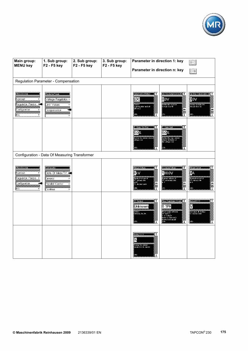
Main group: MENU key
1. Sub group:F2 - F5 key
2. Sub group:F2 - F5 key
3. Sub group:F2 - F5 key
Parameter in direction 1: key
Parameter in direction n: key
Regulation Parameter - Compensation
Configuration - Data Of Measuring Transformer
© Maschinenfabrik Reinhausen 2009 2136339/01 EN TAPCON® 230 175

Main group: MENU key
1. Sub group:F2 - F5 key
2. Sub group:F2 - F5 key
3. Sub group:F2 - F5 key
Parameter in direction 1: key
Parameter in direction n: key
Configuration - General
TAPCON® 230 2136339/01 EN © Maschinenfabrik Reinhausen 2009176

Main group: MENU key
1. Sub group:F2 - F5 key
2. Sub group:F2 - F5 key
3. Sub group:F2 - F5 key
Parameter in direction 1: key
Parameter in direction n: key
Configuration - Parallel Control
© Maschinenfabrik Reinhausen 2009 2136339/01 EN TAPCON® 230 177

Main group: MENU key
1. Sub group:F2 - F5 key
2. Sub group:F2 - F5 key
3. Sub group:F2 - F5 key
Parameter in direction 1: key
Parameter in direction n: key
Configuration - User I/Os
TAPCON® 230 2136339/01 EN © Maschinenfabrik Reinhausen 2009178

Main group: MENU key
1. Sub group:F2 - F5 key
2. Sub group:F2 - F5 key
3. Sub group:F2 - F5 key
Parameter in direction 1: key
Parameter in direction n: key
Configuration - LED Selection
Configuration - Tap Position Options
© Maschinenfabrik Reinhausen 2009 2136339/01 EN TAPCON® 230 179

Main group: MENU key
1. Sub group:F2 - F5 key
2. Sub group:F2 - F5 key
3. Sub group:F2 - F5 key
Parameter in direction 1: key
Parameter in direction n: key
Configuration - Remote Voltage Level
TAPCON® 230 2136339/01 EN © Maschinenfabrik Reinhausen 2009180

Main group: MENU key
1. Sub group:F2 - F5 key
2. Sub group:F2 - F5 key
3. Sub group:F2 - F5 key
Parameter in direction 1: key
Parameter in direction n: key
Configuration - Communication Interface (only TAPCON® 230 expert)
© Maschinenfabrik Reinhausen 2009 2136339/01 EN TAPCON® 230 181

Main group: MENU key
1. Sub group:F2 - F5 key
2. Sub group:F2 - F5 key
3. Sub group:F2 - F5 key
Parameter in direction 1: key
Parameter in direction n: key
Info
TAPCON® 230 2136339/01 EN © Maschinenfabrik Reinhausen 2009182


2136339/01 EN • 1009 • F0204600
©Maschinenfabrik Reinhausen GmbH Fon: +49 (0)941 4090 0Falkensteinstrasse 8 Fax: +49 (0)941 4090 700193059 Regensburg, Germany E-Mail: [email protected]
www.reinhausen.com