engineering mathematics - iv (common to all...
TRANSCRIPT

1 | P a g e
ENGINEERING MATHEMATICS - IV
(Common to all Specializations)
Subject title : Engineering Mathematics-IV
Subject code : 4X01
Periods per week : 4
Total Periods per Semester : 60
Time Schedule with BLUEPRINT
S. No
Major Topic No of Periods
Weightage of Marks
Short Type Essay Type
Unit -I Differential Equations R U App R U App
1 Homogenous Linear Differential Equations with Constant Coefficients
5 6 2 0 0 0 0 0
2 Non-Homogenous Linear Differential Equations with Constant Coefficients
10 23 0 1 0 1 1 0
Unit – II
3 Laplace Transforms 20 32 1 2 1 1 0 1
Unit – III
4 Fourier Series 13 26 1 1 0 0 1 1
Unit – IV
5 Probability 12 23 1 1/2 1/2 1
Total 60 110 5 4 1
2 1/2
2 1/2 3
Marks 15 12 3 25 25 30
R: Remembering type : 40 marks
U: Understading type : 37 marks
App: Application type : 33 marks
Objectives On completion of the subject the student shall be able to: UNIT-I Differential Equations 1.0 Solve Homogeneous linear differential equations with constant coefficients in
engineering situations 1.1 Solve Differential equations of the type (aD
2 +bD + c)y = 0 when the roots of the auxiliary
equation are real and different, real and repeated, complex. 1.2 Solve the higher order homogeneous differential equations with constant coefficients.

2 | P a g e
2 Solve Non Homogeneous linear differential equations with constant coefficients in engineering situations
2.1 Explain the concept of complementary function, particular Integral and general solution of a
differential equation. 2.2 Solve n
th order differential equation of the type f(D) y = X where f(D) is a polynomial of nth
order and X is a function of the form k, eax
, Sinax, Cosax, xn.
UNIT-II 3.0 Use Laplace Transforms to solve differential equation in engineering problems 3.1 Write the definition of Laplace Transform and Laplace transform of standard functions. 3.2 Explain the sufficient conditions of existence of Laplace Transform. 3.3 Write the properties of Laplace Transform – Linear property, First shifting property, Change of
Scale. 3.4 Solve simple problems using the above properties
3.5 Write formulae for Laplace transform of ( )
0
( )( ), , ( ), ( )
tn nf t
t f t f t f u dut in terms of
Laplace transform of ( )f t .
3.6 Solve simple problems using the above formulae. 3.7 Define unit step function and write the Laplace Transform of unit step function. 3.8 Write second shifting property. 3.9 Define inverse Laplace Transform and write inverse Laplace Transform of standard functions. 3.10 Solve simple problems on 3.9 3.11 Write first shifting property of inverse Laplace Transform. 3.12 Solve simple problems on 3.11 3.13 Write inverse Laplace Transforms corresponding to Laplace Transform of the functions
mentioned in section 3.5 3.14 Solve simple problems on 3.13. 3.15 Define convolution of two functions and state convolution theorem. 3.16 Solve simple problems on 3.15. 3.17 Use Laplace and inverse Laplace Transforms to solve simple differential equations of second
order. UNIT-III 4.0 Know Fourier series expansion of functions 4.1 Define the orthogonality of functions in an interval.
4.2 Define Fourier series of a function on the interval ( , 2 )c c and write the Euler‘s formulae
for determining the Fourier coefficients. 4.3 Write sufficient conditions for the existence of Fourier series for a function.
4.4 Find Fourier series of simple functions in the range (0,2 ), ( , ) .
4.5 Write Fourier series for even and odd functions in the interval ( , ) .
4.6 Write Fourier series expansion of a function over the interval ( , )l l
4.7 Write half range Fourier sine and cosine series of a function over the interval (0, )l
4.8 Solve simple problems on 4.5, 4.6 and 4.7
UNIT-IV 5.0 Understand the basic concepts of Probability 5.1 Recall sets, operations on sets and Venn-diagrams. 5.2 Explain the terminology – random experiment, outcome, sample space, elementary event and
event.

3 | P a g e
5.3 Define Probability – Empirical approach and axiomatic approach (Mathematical). 5.4 Prove addition theorem of probability for two mutually exclusive and exhaustive events.
5.5 State addition theorem of probability for three mutually exclusive and exhaustive events. 5.6 Solve simple problems on addition theorem. 5.7 Explain dependent, independent events and conditional event. 5.8 State the formula for conditional probability. 5.9 State multiplication theorem of probability. 5.10 State Bayes‘ theorem. 5.11 Solve simple problems on conditional probability and Bayes‘ theorem. COURSE CONTENT
Differential Equations
1. Homogenous linear differential equations with constant coefficients of order two and higher
with emphasis on second order.
2. Non-homogenous linear differential equations with constant coefficients of the form f(D)y = X
where X is in the form k, eax
, sin ax, cos ax, xn, (n= 1,2) – complimentary function, particular
integral and general solution.
Laplace Transforms(LT)
3. Definition, sufficient conditions for existence of LT, LT of elementary functions, linearity
property, scale change property, first shifting property, multiplication by tn, division by t, LT of
derivatives and integrals, unit step function, LT of unit step function, second shifting theorem,
Inverse Laplace Transforms- shifting theorems and change of scale property, multiplication by
sn and division by s – examples of inverse LT using partial fractions – convolution theorem
(no proof) – applications of LT to solve ordinary differential equations with initial conditions
(2nd
order only)
Fourier Series
4. Orthogonolity of trigonometric functions, Representation of a function in Fourier series over
the interval , 2c c , Euler‘s formulae , sufficient conditions for existence of Fourier
series for a function, even, odd functions and their Fourier series over the interval 0, 2 ,
Change of length of interval – Fourier series , half range series.
Probability
5 Review of sets, operations on sets and Venn-diagrams; random experiment, outcome,
sample space, elementary event and event, equally likely events, Definition of Probability –
Empirical approach and axiomatic approach (Mathematical), addition theorem of probability
for two mutually exclusive and exhaustive events, extension of addition theorem for three
mutually
exclusive and exhaustive events, dependent, independent events and conditional event,
probability of a conditional event, multiplication theorem, Bayes‘ theorem.
Reference Books :
1. Higher Engineering Mathematics, B.V.Ramana, Tata McGraw-Hill 2. Probability, 2/e Schaum‘s Outlines Series, McGraw-Hill 3. Elementary Probability and Statistics, by S.C.Gupta and V.K.Kapoor

4 | P a g e
LINEAR INTEGRATED CIRCUITS APPLICATIONS (COMMON TO ALL SPECIALIZATIONS)
Subject Title : LINEAR INTEGRATED CIRCUITS APPLICATIONS Subject Code : 4X02 Periods/Week : 04 Periods/Year : 60
TIME SCHEDULE WITH BLUE PRINT
OBJECTIVES On Completion of the course the student will be able to 1.0 Understand the working of differential amplifier and operational amplifier. 1.1. Describe the circuit of differential amplifier. 1.2. Explain the operation of differential amplifier. 1.3. List the limitations of differential amplifier constructed using discrete components 1.4. Explain the operational amplifier. 1.5. Sketch the block diagram and list the different blocks in operational amplifier 1.6. Discuss the power supply requirements for an operational amplifier 1.7. List the basic specifications of ideal operational amplifier. 1.8. Define CMRR. Discuss the need for high CMRR 1.9. Discriminate how an integrated operational amplifier circuit overcomes the limitations of
discrete operational amplifier. 1.10. Sketch the pin diagram of metal can package and dual in line package for typical IC CA 741
or equivalent. 1.11. Define the terms input offset voltage, input offset current, input bias current, input resistance,
input capacitance, offset voltage adjustment range, supply voltage rejection ratio, output voltage swing, large signal voltage gain, slew rate, gain bandwidth product, supply current with reference to operational amplifier.
1.12. Describe the open loop operations of an operational amplifier.
2.0 Understand applications of operational amplifier 2.1 Discuss the effects of negative feedback on an operational amplifier 2.2 Sketch and explain the circuits of non-inverting, inverting operational amplifier, 2.3 Sketch and explain the circuits of summing amplifier, difference amplifier, voltage follower
and differentiator, integrator, comparator, Voltage-current converter, current-Voltage converter.
2.4 Sketch and explain circuits of Astable, Monostable, Bistable multivibrators and Schmitt trigger using OP-amp.
2.5 Sketch and explain triangular generator circuit using Op-amp .
Sl. No
Major Topics
No. Of
Periods
Weightage of
Marks
Remember
Understanding
Applying
Analyzin
g Short Type
Essay Type
1 Operational Amplifiers
15 29 10 10 03 03 3 2
2 Operational Amplifiers applications
20 34 13 13 00 00 3 2 ½
3 A/D and D/A Converters
10 21 2 1 ½
4 Timers, PLL & IC regulators
15 26 10 10 03 03 2 2
Total 60 110 53 52 06 09 10 8

5 | P a g e
2.6 Draw and explain OP-Amp Wein-bridge Oscillator 2.7 Discuss the limitations of passive filters 2.8 Describe briefly about active filters 2.9 Sketch and describe circuits of LPF, HPF, and BPF first order using OPAMP. 2.10 Sketch and explain Bootstrap sweep circuit, Miller sweep circuit using Op-amp. 2.11 Sketch the input and output waveforms for Miller and Bootstrap sweep circuits.
3.0 Understand A/D and D/A Converters. 3.1. State the need for A/D and D/A converters. 3.2. Explain the terms resolution, Accuracy, Monotonicity and settling time of D/A converter. 3.3. Explain D/A conversion using binary weighted resistors. 3.4. Explain D/A conversion using R-2R ladder network. 3.5. Explain A/D conversion using counter method. 3.6. Explain A/D conversion using successive approximate method 4.0 Understand operation of timer, PLL and IC regulators 4.1 Draw the block diagram of 555 IC and explain 4.2 Sketch and explain the AMV & MMV using IC 555 4.3 Draw the block diagram of 565 IC PLL and explain 4.4 Sketch and explain the frequency multiplier ,frequency detector, FSK detector using IC 565 4.5 List the type of I.C. regulators like 78XX, 79XX and give its advantages. 4.6 Explain the operation of fixed positive and negative voltage regulators.(using 7800 series and
7900 series) 4.7 Indicate brief description of SMPS. COURSE CONTENTS 1. OPERATIONAL AMPLIFIER:
Differential amplifiers, block diagram of operational amplifiers, definition of input offset voltage, input offset current, bias current, differential input resistance, input capacitance, and offset voltage adjustment range, CMRR, SVR, SR, GBW, equivalent circuit of OP-amp.
2. OPERATIONAL AMPLIFIER APPLICATIONS
Summer, voltage follower, difference amplifier, comparator, Integrator, differentiator, active filters first & second order, Voltage to current converter, current to voltage converter. Op-amp circuits for Schmitt trigger, monostable and astable circuits Miller and bootstrap sweep circuits, current sweep circuit, active filters first order
3. A/D AND D/A CONVERTERS A/D and D/A Converters, define the terms the terms resolution, Accuracy, Monotonicity and settling time of D/A converter. DAC and ADC using op-Amps.
4. TIMER, PLL AND IC REGULATORS
555 IC, AMV & MMV using IC 555, 565 IC PLL, frequency multiplier ,frequency detector, FSK detector using IC 565, I.C. regulators like 78XX, 79XX, SMPS
REFERENCE BOOKS 1. Electronic Devices and circuits by Milliman & Halkies 2. Operational Amplifiers and Linear Integrated circuits by Ramakanth Gayakwad 3. Applied Electronics by G.K. Mithal 4. Pulse fundamentals by John Doyle 5. Basic Electronics And Linear circuits by N.N. Bhargava,D.C. Kulshreshtha,S.C.Gupta.

6 | P a g e
PULE & DIGITAL CIRCUITS (Common to all Specializations)
Subject Title : PULE & DIGITAL CIRCUITS Subject Code : 4X03 Periods / Week : 4 Periods / Year : 60
TIME SCHEDULE
OBJECTIVES On completion of the course the student will be able to know 1.0 Understand wave shaping circuits. 1.1 Define the terms pulse width, rise time, fall time, tilt, over shoot, under shoot, PRT, PRF and
duty cycle with reference to a pulse. 1.2 Define the term linear wave shaping 1.3 Define time constant of a RC circuit 1.4 Sketch a RC low pass circuit 1.5 Sketch the output voltage wave shape for a low pass RC circuit for a step pulse and square
wave input voltages 1.6 Indicate the expression for upper 3 db frequency. 1.7 Indicate the rise time expression 1.8 Analyze a low pass RC circuit as an integrator. 1.9 Sketch high pass RC circuit 1.10 Predict the response of high pass RC circuit 1.11 Illustrate the expression for the lower 3db frequency 1.12 Analyze a high pass RC circuit as differentiator 1.13 Explain the applications of integrator and differentiator. 1.14 Explain the term Non-linear wave shaping. 1.15 Explain the operation of series, shunt biased clipper circuits.(both positive & negative) 1.16 Sketch the double diode clipper or slicer circuit. 1.17 Sketch a Zener diode clipper for clipping at any level on both positive and negative half cycle
and double clipping. 1.18 Explain the operation of above circuit. 1.19 Explain the diode clamper circuit.(both positive & negative)
1.20 List the applications of clipper and clamper circuits. 2.0 Understand the Working of a Multivibrators and sweep circuits. 2.1. Sketch the circuit diagram of a transistor switch and explain how it acts as a switch. 2.2. Define Multivibrator and classify them on the basis of the no of stable states. 2.3. Sketch and explain the circuit of Bistable Multivibrator using transistor. 2.4. Sketch and explain the Monostable circuit using transistor. 2.5. Sketch and explain Astable Multivibrator using transistor. 2.6. Sketch and explain the Schmitt trigger circuit using transistors.
S No
Major Topics No. of
Periods
Weight age of Marks
Short Type
Essay Type
1 Wave shaping circuits 20 29 3 2
2 Multivibrators & Sweep Circuits
20 39 3 3
3 Logic families 12 26 2 2
4 Displays and Semiconductor Memories
8 16 2 1
Total 60 110 10 8

7 | P a g e
2.7. List the applications of Multivibrators. 2.8. Define sweep signal. 2.9. Distinguish between voltage time base and current time base generators 2.10. Sketch a simple sweep circuit using transistor constant current circuit and explain its
operation. 2.11. Sketch and explain Bootstrap sweep circuit & Miller sweep circuit. 2.12. List the applications of sweep circuits. 3.0 Comprehend the working of Logic families 3.1 Know the classification of logic families 3.2 Define positive and negative logic families 3.3 Define logic families characteristics such as logic levels, Propagation delay, noise margin, fan
in & fan out and power dissipation 3.4 Draw an open collector TTL NAND gate and its explain its working 3.5 State the use of pull up resistor 3.6 Draw and explain TTL NAND gate with totem pole output 3.7 Draw an ECL gate circuit and explain its working for NOR gate 3.8 State the need for a tri-state buffer/NOT gate 3.9 Draw the simplified diagram of a tri-state buffer/NOT gate and explain 3.10 Draw a CMOS NAND gate circuit and explain 3.11 Compare the performance of TTL gate with that of CMOS gate and ECL gate
4.0 Understand working of display devices and Semiconductor memories
4.1. State the use of display circuits using LEDs and LCDs 4.2. Distinguish between common anode 7-segment LED display 4.3. State the advantages of LCD display 4.4. List the types of memories 4.5. Define memory terminology such as Read, Write, Access time, Capacity, Word length,
Address, Volatile and Non-volatile memories, Static and Dynamic memories, Random access, Sequential access
4.6. Differentiate between ROM & RAM 4.7. Explain the working of a basic bipolar RAM - cell 4.8. State the advantages and disadvantages of dynamic RAM over static RAM's 4.9. Expansions of memories capacity and word size 4.10. State the use of PROM 4.11. Distinguish between UV EPROM and EPROM COURSE CONTENTS 1. WAVE SHAPING CIRCUITS:
Specifications of pulse and pulse waveform, review of transients in RC circuits, differentiator and integrator circuits. Clipping circuits using diodes and Zener diodes, clipping at various levels, double clipping. Clamping circuits using diodes. 2. MULTIVIBRATORS & SWEEP GENERATORS :
Transistor as a switch, transistor Bistable Multivibrator, and Schmitt trigger collector coupled Monostable Multivibrators, wave forms, gating period calculations, triggering, maximum frequency, collector coupled Astable Multivibrator, wave form frequency calculations. Miller and bootstrap sweep circuits, current sweep circuit.
1. Logic families : Positive & Negative logic inputs, TTL logic, open-collector and totem pole output & tristate logic gates, 74 & 54 series of ICs – Propagation delay or speed, noise margin, logic levels, power dissipation, fan - in / fan - out. CMOS circuits and comparison with TTL circuits; basic concepts of ECL (emitter coupled logic).
2. Displays and Semiconductor Memories: Uses of LED, LCD. Concept of memory using registers; working principles of ROM, PROM, EPROM and EEPROM. Static and Dynamic RAMs , Expansions of memories capacity and word size.

8 | P a g e
TEXT BOOKS 1. Digital Design by Morris Mano 2. Digital principles and Applications by Malvino & Leach(THM) 3. Digital Electronics by Tokheim 4. Principles of electronics by Malvino 5. Electronic Devices and circuits by Milliman & Halkies 6. Pulse, digital and switching waveform by Milliman and Taub 7. Operational Amplifiers and Linear Integrated circuits by Ramakanth Gayakwad 8. Applied Electronics by G.K. Mithal 9. Pulse fundamentals by John Doyle 10. Pulse and wave shaping circuits by Agarwal. 11. Basic Electronics And Linear circuits by N.N. Bhargava,D.C. Kulshreshtha,S.C.Gupta.
REFERENCE BOOKS
1. Digital Electronics by Gothmans 2. Digital Electronics by Walkerly
9 | P a g e
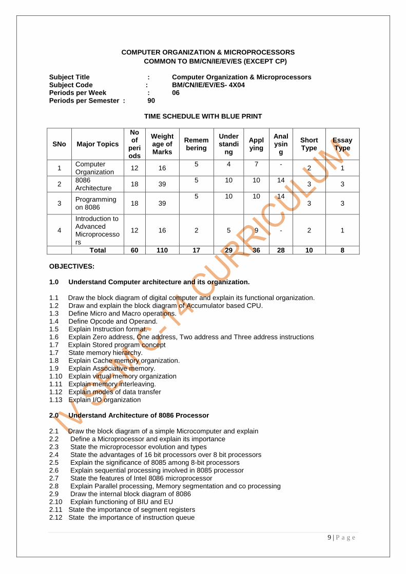
COMPUTER ORGANIZATION & MICROPROCESSORS
COMMON TO BM/CN/IE/EV/ES (EXCEPT CP)
Subject Title : Computer Organization & Microprocessors Subject Code : BM/CN/IE/EV/ES- 4X04 Periods per Week : 06 Periods per Semester : 90
TIME SCHEDULE WITH BLUE PRINT
SNo Major Topics
No of
periods
Weightage of Marks
Remembering
Understandi
ng
Applying
Analysin
g
Short Type
Essay Type
1 Computer Organization
12 16 5 4 7 -
2 1
2 8086 Architecture
18 39 5 10 10 14
3 3
3 Programming on 8086
18 39 5 10 10 14
3 3
4
Introduction to Advanced Microprocessors
12 16 2 5 9 - 2 1
Total 60 110 17 29 36 28 10 8
OBJECTIVES: 1.0 Understand Computer architecture and its organization.
1.1 Draw the block diagram of digital computer and explain its functional organization. 1.2 Draw and explain the block diagram of Accumulator based CPU. 1.3 Define Micro and Macro operations. 1.4 Define Opcode and Operand. 1.5 Explain Instruction format. 1.6 Explain Zero address, One address, Two address and Three address instructions 1.7 Explain Stored program concept 1.7 State memory hierarchy. 1.8 Explain Cache memory organization. 1.9 Explain Associative memory. 1.10 Explain virtual memory organization 1.11 Explain memory interleaving. 1.12 Explain modes of data transfer 1.13 Explain I/O organization 2.0 Understand Architecture of 8086 Processor
2.1 Draw the block diagram of a simple Microcomputer and explain 2.2 Define a Microprocessor and explain its importance 2.3 State the microprocessor evolution and types 2.4 State the advantages of 16 bit processors over 8 bit processors 2.5 Explain the significance of 8085 among 8-bit processors 2.6 Explain sequential processing involved in 8085 processor 2.7 State the features of Intel 8086 microprocessor 2.8 Explain Parallel processing, Memory segmentation and co processing 2.9 Draw the internal block diagram of 8086 2.10 Explain functioning of BIU and EU 2.11 State the importance of segment registers 2.12 State the importance of instruction queue

10 | P a g e
2.13 Define the usage of General Purpose Registers 2.14 State the purpose of Pointer registers 2.15 State the usage of Index registers 2.16 Explain how to generate 20 bit physical address with examples 2.17 Define the functions of the Flags of 8086 and draw Flag register 2.18 Draw PIN out of 8086 and state function of each pin 2.19 Explain the interrupt types used in 8086 2.20 Explain the interrupt response of 8086 microprocessor 2.21 Draw and explain BUS organization in MIN mode 2.22 Draw and explain BUS organization in MAX mode 3.0 Know assembly language programming on 8086
3.1 Explain various addressing modes of 8086 3.2 State the general and widely used instruction format of 8086 3.3 Explain constructing machine codes for MOV instruction for different addressing modes 3.4 Classify the Instruction set of 8086 3.5 Explain Data Transfer group of Instructions with examples 3.6 Explain various Arithmetic group of Instructions with examples 3.7 Explain Logical group of Instructions 3.8 Explain string instructions with examples 3.9 Explain Branch instructions with examples 3.10 Explain Process control instructions 3.11 State the Interrupt related instructions 3.12 Write simple programs like 16-bit addition ,subtraction ,multiplication and division 3.13 Write the standard program format. 3.14 State various assembler directives. 3.15 Explain software development tools : Assembler, Editor, Linker and Debugger 3.16 Write simple programs using assembler directives 3.17 Define procedure, macro and parameters 3.18 State the differences between procedure and macro 3.19 Explain the program flow for single and nested procedures 3.20 Explain the four different ways of passing parameters to and from a procedure with examples 3.21 Explain passing parameters to macros 3.22 Explain the debugging methods of an assembly language program 4.0 Understand the Architecture of 80286 and features of 386 , 486 and Pentium
4.1 State the features of 80286microprocessor 4.2 Describe the architecture of 80286 4.3. Explain operating modes of 80286 4.4 Describe memory management of 80286. 4.5 State the features of 80386 4.6 Describe pipe lining. 4.7 Describe instruction level parallelism. 4.8 Compare RISC and CISC. 4.9 State the features of 80486 4.10 Explain the super scalar architecture 4.11 State the features of Pentium microprocessor COURSE CONTENTS: 1. Computer Organization
Basic block diagram- Accumulator based CPU- Micro & Macro operations-Instruction format-Memory organization-Cache memory-Associative memory –-Memory interleaving
2. 8086 Architecture
Block diagram – CPU architecture – Pin diagram of 8086/88 Internal operation – System bus architecture of 8086 in minimum & maximum modes –interrupt structure of 8086

11 | P a g e
3. Programming of 8086
Addressing modes - Instruction formats and Instruction set of 8086 - Assembly language programming & programming with procedures & macros
4. Architecture of 80286, 386 ,486 and Pentium
Features of all processors- Architectures of 80286, 386 , 486 and Pentium –Operating modes -Memory organization in 286 and 386, Super scalar architecture,
TEXT BOOKS 1 Computer Architecture and Organization–John P. Hayes 2. Computer System Architecture- Morris Mano 3. The Intel Microprocessors – Barry and Brey (6
thed)
4. Microprocessors and Interfaces – Douglas V.Hall(3rd
ed) REFERENCE BOOKS 1. Computer Architecture and Parallel Processing- Kai Hwang and Faye A Briggs 2. The 8086/8087 family Microprocessors – Yu Cheng Liu Glen A. Gibson 3. Advanced Microprocessors – Daniel Tabak

12 | P a g e
MICROPROCESSORS
(ONLY FOR CP)
Subject Title : Microprocessors Subject Code : CP- 4X04 Periods per Week : 04 Periods per Semester : 60
TIME SCHEDULE WITH BLUE PRINT
Sl.No
Major Topics No. of period
s
Weightage of Marks
Remembering
Understanding
Applying
Analyzing
Short Type
Essay Type
1 8085 Architecture
15 16 5 4 7 - 2 1
2 8086 Architecture
18 39 5 10 10 14 3 3
3 Programming on 8086
15 39 5 10 10 14 3 3
4
Introduction to Advanced Microprocessors
12 16 2 5 9 - 2 1
Total 60 110 17 29 36 28 10 8
OBJECTIVES:
1.0 Understand Architecture of Intel 8085 Microprocessor 1.1 Draw the block diagram of a Microcomputer and understand the functions of various
units 1.2 Know the difference between Microprocessor and Microcomputer 1.3 List the applications of Microprocessor 1.4 Know the evolution of Microprocessors 1.5 State the features of Intel 8085 Microprocessor 1.6 Draw the functional block diagram of 8085 and know its operation 1.7 Know the purpose of general purpose registers, ALU 1.8 Know the function of Program Counter, Instruction Register, Instruction Decoder and
Control unit. 1.9 Know about the flags of 8085 1.10 Know about stack and stack pointer 1.11 Know about the necessity of interrupt 1.12 Know about types of interrupts and their priority in 8085
2.0 Understand Architecture of 8086 Processor
2.1 Give the advantages of 16 bit processors over 8 bit processors
2.2 State the features of Intel 8086 microprocessor 2.3 Draw the internal block diagram of 8086 2.4 Explain functioning of BIU and EU 2.5 Know about the concept of segmentation, importance of segment registers,
Pointer registers 2.6 Know the importance of instruction queue 2.7 Know about the General Purpose Registers 2.8 Know the usage of Index registers

13 | P a g e
2.9 Explain how to generate 20 bit physical address with examples 2.10 Know the structure of flag register and functions of various flags 2.11 Draw pin diagram of 8086 and state function of each pin 2.12 Know various types of interrupts in 8086 2.13 Explain the interrupt response of 8086 microprocessor 2.14 Explain the interrupt vector table of 8086 microprocessor 2.15 Know I/O organization methods: Memory mapped I/O and I/O mapped I/O 2.16 Draw and explain BUS organization in MIN mode 2.17 Draw and explain BUS organization in MAX mode
3.0 Know assembly language programming on 8086 3.1 Explain various addressing modes of 8086 3.2 Explain constructing machine codes for MOV instruction for different addressing modes 3.3 Classify the Instruction set of 8086 3.4 Explain Data Transfer group of Instructions with examples 3.5 Explain various Arithmetic group of Instructions with examples 3.6 Explain Logical group of Instructions 3.7 Explain string instructions with examples 3.8 Explain Branch instructions with examples 3.9 Explain Process control instructions 3.10 Know the Interrupt related instructions 3.11 Write simple programs like 16-bit addition, subtraction, multiplication and division 3.12 State various assembler directives. 3.13 Know the standard program format. 3.14 Write simple programs using assembler directives 3.15 Define procedure, macro and parameters 3.16 Give the differences between procedure and macro 3.17 Explain the program flow for single and nested procedures 3.18 Explain the debugging methods of an assembly language program
4.0 Understand the Architecture of 80286 and features of 386 , 486 and Pentium 4.1 State the features of 80286 microprocessor 4.2 Describe the architecture of 80286 4.3 Explain operating modes of 80286 4.4 Describe memory management of 80286. 4.5 State the features of 80386 4.6 Describe pipe lining. 4.7 Describe instruction level parallelism. 4.8 Compare RISC and CISC. 4.9 State the features of 80486 4.10 Explain the super scalar architecture 4.11 State the features of Pentium microprocessor
COURSE CONTENTS
1. 8085 Architecture
Microcomputer and Microprocessor- Evolution of Microprocessors- Block diagram of 8085
Microprocessor- Functioning of various units of 8085 – Registers, PC, Stack, Interrupts
2. 8086 Architecture
Block diagram – CPU architecture – Pin diagram of 8086/88 Internal operation – System bus
architecture of 8086 in minimum & maximum modes –interrupt structure of 8086 – I/O
organization methods

14 | P a g e
3. Programming of 8086
Addressing modes - Instruction formats and Instruction set of 8086 - Assembly language
programming & programming with procedures & macros
4. Architecture of 80286, 386 ,486 and Pentium Features of all processors- Architectures of 80286, 386 , 486 and Pentium –Operating modes -Memory organization in 286 and 386, Super scalar architecture,
TEXT BOOKS
1. Microprocessor Architecture, and Applications - Ramesh S.Gaonkar 2. Microprocessors and Interfaces – Douglas V. Hall(3rd ed) 3. The Intel Microprocessors – Barry and Brey (6th ed)
REFERENCE BOOKS
1. The 8086/8087 family Microprocessors – Yu Cheng Liu Glen A. Gibson 2. Microprocessors and Interfacing – N.Marriwala

15 | P a g e
16 | P a g e
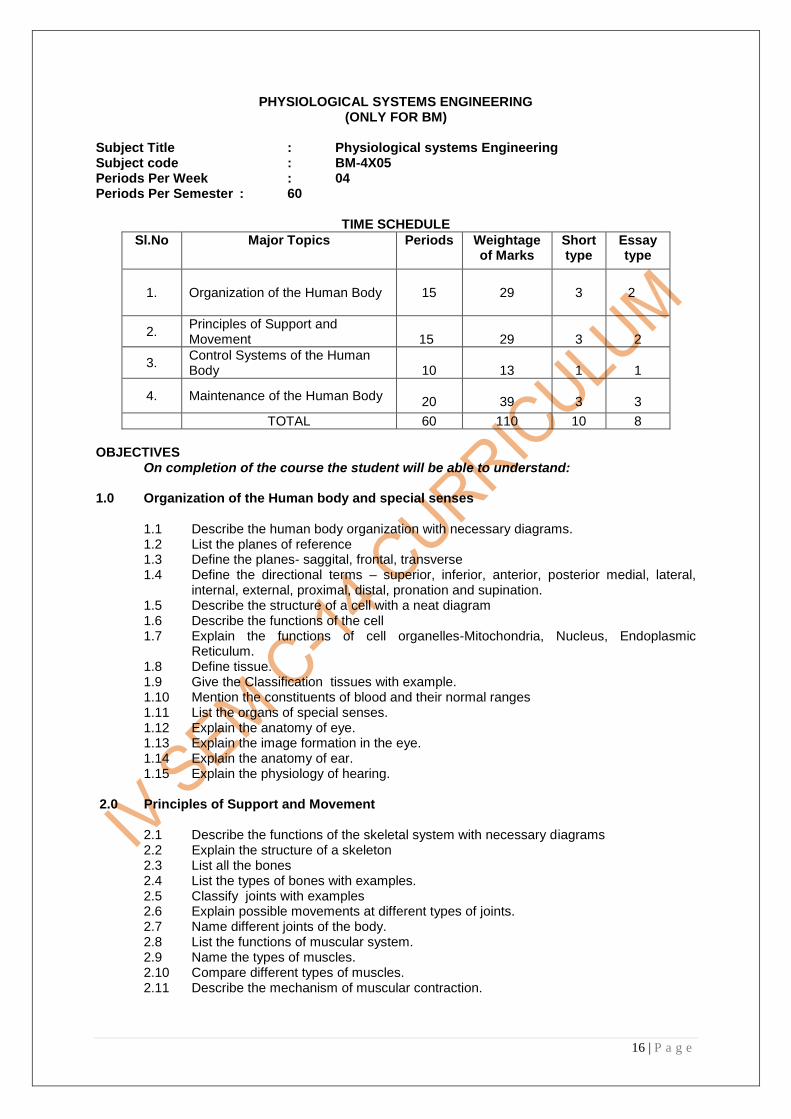
PHYSIOLOGICAL SYSTEMS ENGINEERING (ONLY FOR BM)
Subject Title : Physiological systems Engineering Subject code : BM-4X05 Periods Per Week : 04 Periods Per Semester : 60
TIME SCHEDULE
Sl.No Major Topics Periods Weightage of Marks
Short type
Essay type
1. Organization of the Human Body
15
29 3
2
2. Principles of Support and Movement
15
29
3
2
3. Control Systems of the Human Body
10
13
1
1
4. Maintenance of the Human Body
20
39 3
3
TOTAL 60 110 10 8
OBJECTIVES On completion of the course the student will be able to understand: 1.0 Organization of the Human body and special senses
1.1 Describe the human body organization with necessary diagrams. 1.2 List the planes of reference 1.3 Define the planes- saggital, frontal, transverse 1.4 Define the directional terms – superior, inferior, anterior, posterior medial, lateral,
internal, external, proximal, distal, pronation and supination. 1.5 Describe the structure of a cell with a neat diagram 1.6 Describe the functions of the cell 1.7 Explain the functions of cell organelles-Mitochondria, Nucleus, Endoplasmic
Reticulum. 1.8 Define tissue. 1.9 Give the Classification tissues with example. 1.10 Mention the constituents of blood and their normal ranges 1.11 List the organs of special senses. 1.12 Explain the anatomy of eye. 1.13 Explain the image formation in the eye. 1.14 Explain the anatomy of ear. 1.15 Explain the physiology of hearing.
2.0 Principles of Support and Movement
2.1 Describe the functions of the skeletal system with necessary diagrams 2.2 Explain the structure of a skeleton 2.3 List all the bones 2.4 List the types of bones with examples. 2.5 Classify joints with examples 2.6 Explain possible movements at different types of joints. 2.7 Name different joints of the body. 2.8 List the functions of muscular system. 2.9 Name the types of muscles. 2.10 Compare different types of muscles. 2.11 Describe the mechanism of muscular contraction.

17 | P a g e
3.0 Control Systems of the Human Body 3.1 Explain the structure of a neuron.
3.2 Define resting potential and action potential. 3.3 Explain conduction of nerve impulses in unmyelinated and myelinated nerve fibers. 3.5 Describe synapse and neuromuscular junction with diagram. 3.6 Describe Anatomy of brain 3.7 List the functions of brain. 3.8 Explain the structure and functions of spinal cord. 3.9 Describe reflex action.
4.0 Maintenance of the Human Body
4.1 Describe the structure of heart with diagram. 4.2 Explain various circulations – systemic, pulmonary, coronary and portal circulation 4.3 List the major blood vessels. 4.4 Explain the events in the cardiac cycle 4.5 Calculate the heart rate for given cardiac cycle 4.6 Describe conduction system of the heart 4.7 Explain the structure and functions of respiratory System 4.8 Explain the mechanism of breathing 4.9 Define tidal volume, residual volume, forced expiratory volume, forced inspiratory
volume, vital capacity, total lung capacity, forced reserved capacity 4.10 Explain the functions of the digestive system- secretion, digestion and absorption 4.11 Describe the structure of the digestive system 4.12 Describe the functional anatomy of a kidney with necessary diagram 4.13 Draw and Explain the structure of nephron 4.14 Explain the functioning of a nephron 4.15 Explain the structure of Urinary system 4.16 Explain the functioning of the urinary system
COURSE CONTENTS
1. Organization of the human body and special senses : Cellular level , Tissue level, Organ level, planes of reference , directional terms, Cell Structure, Organelles and functions. Tissues, Blood Composition and functions. structure of eye, image formation, structure of ear and physiology.
2. Principles of Support and Movement : Functions and structure of the skeletal system, types of bones, joints, and their classification , different joints of the body. Functions of muscular system, types of muscles and their comparison, mechanism of muscular contraction.
3. Control System of the Human Body: Structure and functions of neuron, action potential, conduction of nerve, impulses, synapse and neuromuscular junction, structures and function of the brain.
4. Maintenance of the Human Body: Structure and function of the heart, major blood vessels in system, pulmonary and coronary circulation, cardiac cycle, Organs of respiration and their function, mechanics of breathing , lung volumes and capacities. Functions of the digestive system. Functional anatomy of a kidney, structure and functions of nephron.
TEXTBOOKS
1. Concepts of Human Anatomy and Physiology - Kent. M. Van de graft and Stuarat Ira (Mc Graw Hill)
2. Spears Anatomy and Physiology for Nurses - Smith and Windod. REFERENCEBOOK
Principles of Anatomy and Physiology By Tortora and Grabowski.

18 | P a g e
DIGITAL COMMUNICATIONS (ONLY FOR CN)
Subject Title : Digital communications
Subject Code : CN-4X05
Periods / Week : 04 Periods / Semester : 60
TIME SCHEDULE ALONG WITH BLUE PRINT
S.No
Major Topics Periods Weightage of
Marks Short type
Essay type
1 Digital modulation techniques
15 29 3 2
2 Digital transmission 10 21 2 11/2
3 Digital data Modulation Techniques
20 34 3 21/2
4 Telephone Switching systems
15 26 2 2
TOTAL 60 110 10 8
OBJECTIVES On completion of the course content the student will be able to
1.0 Understand the principles of Digital modulation techniques 1.1. Explain digital signals. 1.2. Compare analog and digital communication techniques. 1.3. Define the terms average information, information rate and channel capacity 1.4. State the relation between information rate and channel capacity 1.5. State sampling theorem and explain its significance. 1.6. Classify pulse modulation techniques. 1.7. Define PAM,PWM and PPM 1.8. State the advantages and disadvantages of PAM 1.9. Explain the generation and demodulation of PAM with block diagram. 1.10. List the advantages and disadvantages of PAM. 1.11. Describe PWM and PPM with waveforms. 1.12. List three advantages and disadvantages of PWM 1.13. List three advantages and disadvantages of PPM 1.14. Compare PAM, PWM and PPM. 1.15. Explain different sampling techniques. 1.16. Define quantizing noise and methods to reduce it. 1.17. Define quantization, bit rate, and dynamic range for PCM systems. 1.18. Describe the coding and decoding of a PCM signal. 1.19. Define companding and explain analog companding and digital companding 1.20. Explain the different types of vocoders 1.21. Explain delta modulation with block diagram 1.22. Explain slope overload & granular noise 1.23. Explain adaptive delta modulation with block diagram 1.24. Explain differential pulse code modulation. 1.25. Compare the above systems 1.26. Explain single and multichannel PCM-TDM system 1.27. Applications of PCM, DM, ADM, DPCM 2.0 Discuss the principles of digital transmission 2.1. Explain the effect of noise on digital data communication system

19 | P a g e
2.2. Explain different line coding schemes digital transmission 2.3. List different types of errors during data transmission 2.4. Explain about error control 2.5. Mention different error detection techniques 2.6. Explain error detection codes- parity check method, VRC method, LRC method , check sum
method, CRC method 2.7. List different error correction techniques. 2.8. Explain retransmission method of error correction. 2.9. Explain symbol substitution method of error correction. 2.10. Explain importance of hamming code in error detection and correction. 2.11. List the advantages of digital transmission
3.0 Understand various Digital data Modulation Techniques. 3.1. State the need for digital modulation 3.2. Explain the difference between bit rate and baud rat 3.3. List the three basic types of digital modulation techniques. 3.4. Define ASK,FSK and PSK 3.5. Explain ASK modulator with block diagram. 3.6. Explain ASK coherent demodulator with block diagram 3.7. List four advantages of ASK 3.8. List two disadvantages of ASK 3.9. Explain BFSK modulator with block diagram. 3.10. Explain Coherent BFSK demodulator. 3.11. Draw and explain FSK demodulator using PLL. 3.12. List two advantages and disadvantages of FSK 3.13. Draw and explain BPSK modulator. 3.14. Draw and explain BPSK demodulator. 3.15. List four advantages of BPSK 3.16. State the importance of Constellation diagram. 3.17. Explain QPSK and 8 PSK with constellation diagrams briefly 3.18. Compare ASK, FSK and PSK. 3.19. Explain Quadrature Amplitude Modulation (QAM). 3.20. State typical application areas of different digital modulation techniques. 3.21. State the need for multiplexing 3.22. Explain Frequency Division Multiplexing 3.23. Explain Time Division Multiplexing. 3.24. List four advantages of TDM 3.25. List three disadvantages of TDM 3.26. Compare TDM and FDM 3.27. Explain the working principle of statistical multiplexer with block diagram 3.28. Compare TDM and statistical multiplexing
4.0 Discuss the principles of Telephone switching systems 4.1. Classify different switched telephone systems. 4.2. Describe the topology of the switched telephone network. 4.3. Mention the advantages of electronic telephony over manual telephony. 4.4. Define local loop in telephone system. 4.5. Mention various signals present on a local-loop telephone line. 4.6. State the functions of various signals present on a local-loop telephone line. 4.7. List the types of dialling. 4.8. Explain pulse dialling and DTMF. 4.9. State the advantages of DTMF. 4.10. Define cross talk and explain methods to eliminates cross talk 4.11. Explain the principle of common control 4.12. Explain the concept of SPC 4.13. Explain the working of centralized SPC 4.14. Explain the working of distributed SPC 4.15. Compare in-band and out-of-band signalling systems for telephony. 4.16. Explain briefly the use of Signal system Seven(SS7). 4.17. Explain the use of FDM in telephony

20 | P a g e
4.18. Explain the use of TDM in telephony. 4.19. State the need for EPABX 4.20. List important functions of EPABX 4.21. Explain the use of FAX machine. 4.22. Explain Internet telephony. 4.23. Explain IP telephony (VOIP).
COURSE CONTENTS 1.0 Digital Communication and Digital Modulation.
Introduction to digital communication, Sampling theorem, pulse modulation, pulse code modulation, delta modulation, vocoders and data compression techniques.
2.0 Digital transmission. Data coding, asynchronous transmission, synchronous Transmission, error detection and correction: Parity check, VRC, LRC, Checksum, CRC, hamming code, symbol substitution method.
3.0 Digital data Modulation Techniques
Digital modulation, Amplitude shift keying(ASK), frequency shift keying (FSK), phase shift keying (PSK), QPSK,8PSK, Constellation diagrams, quadrature amplitude modulation (QAM). Multiplexing techniques: FDM and TDM, Telephone modem, fax modem and data modem, cable modem, digital subscriber lines, ADSL,ISDN
4.0 Telephone System. Public switched telephone network(PSTN), manual and electronic Telephony , the local loop, signals on local loop, in band and out band signaling, SS-7system,FDM and TDM in telephony, EPABX, FAX, Internet telephony.
REFERENCE BOOKS 1. Electronic communication systems by George Kennedy 2. Electronic communication by Roddy & Coolen 3. Tele communication switching systems and networks by Thiagarajan viswanathan 4. Tele communication system engineering by Roger L. Freeman 5. Electronic communication systems by wayne tomasi, pearson education 6. Radio engineering by G.K. Mithal. 7. Fibre optics in telecommunication by N. Sharma (Tata Mc Graw Hill) 8. Optical Fibre commnunication by G. Keiser. 9. Electronic communication system by Wayne Tomasi (Pearson education) 10. Communication Electronics Principles & Applications by Frenzel.

21 | P a g e
C++ WITH DATA STRUCTURES
(ONLY FOR CP)
Subject title : C++ with Data Structures Subject Code : CP – 4X05 Periods per Week : 05 Periods per Semester : 75
TIME SCHEDULE WITH BLUE PRINT
S. No. Major Topics No. of period
s
Weightage of Marks
Short
Type
Essay
Type
Remember
Understand
Apply
Analyze
Evaluate
Create
1 Introduction to OOPs concept .
15 16 2 1 6 10
2
Understand arrays, pointers, and references & Inheritance
20 26 2 2 6 10 10
3 Understand the C++ I/O
15 26 2 2 3 8 15
4 Data Structures 10 26 2 2 3 13 10
5 Trees , Sorting & Searching
15 16 2 1 3 3 10
TOTAL 75 110 10 8 21 44 45
OBJECTIVES
On Completion of the course the student will be able to know
1.0 Introduction to OOPs Concept 1.1 To Appreciate the evolution of OOPS. 1.2 To describe the principle of object oriented language. 1.3 To explain OOPS properties like encapsulation, polymorphism and inheritance. 1.4 To discuss portability and standards of C++ language 1.5 To describe how to Create, compile, link and execute a C++ program. 1.6 To give the structure of C++ program 1.7 To explain C++ I/O operation with an examples. 1.8 To write comment statements in C++. 1.9 To list out keywords of C++ other than those used in C 1.10 To define a class and object of C++ 1.11 To explain a class constructor and destructor. 1.12 To describe the declaration, definition and usage of classes. 1.13 To explain a friend function and its necessity. 1.14 To describe how to distinguish between classes , structures and unions. 1.15 To apply the declaration and advantages of inline functions. 1.16 To describe how to pass objects to functions. 1.17 To describe how to return the objects from functions 1.18 To write a program how to pass objects to functions 1.19 To write a program how to return objects from functions 1.20 To explain the concept of operator overloading with an example. 1.21 To explain the concept of function overloading with an example. 1.22 To explain the concept of polymorphism with an example.

22 | P a g e
2.0 Understand the concepts of Arrays, Pointers, References and Inheritance .
2.1 To explain the declarations and accessing of array of objects. 2.2 To describe the declaration and accessing of pointers to objects. 2.3 To describe the usage of this operator. 2.4 To describe the operation of dynamic memory allocation like new, delete. 2.5 To describe the declarations and uses of references. 2.6 To describe how to relate base class and derived class. 2.7 To define a derived class with syntax. 2.8 To explain the three types of access control private, public and protected. 2.9 To explain the types of inheritances with an examples 2.10 To describe the virtual base classes with an examples.
3.0 Understand the Concept of C++ I/O
3.1 To list the C++ I/O operators and give their meaning. 3.2 To explain the basics of formatted I/O. 3.3 To Discuss about I/O manipulators and give at least five examples. 3.4 To describe the file I/O and stream classes. 3.5 To explain the binary I/O functions like get and put. 3.6 To describe the format and working of file I/O functions like open, read, write, cout etc. 3.7 To explain the operator overloading with an example 3.8 To define a virtual function and their applications. 3.9 To write programs using file I/O functions.
4.0 Understand the concept of Data Structures 4.1 To define linear and non linear data structures 4.2 To describe about linked lists 4.3 To explain about types of linked lists like Singly Linked, doubly Linked, Circular, Circular Linked Lists.
4.4 To describe how to represent a linked list in memory. 4.5 To explain how to insert and delete a node into/from a linked list. 4.6 To define a Stack with an example. 4.7 To describe how to represent a stack using Arrays and Liked Lists, 4.8 To explain about stack operations like PUSH and POP, 4.9 To define a Queue with an example. 4.10 To describe how to represent a queue using Arrays and Liked Lists. 4.11 To explain about queue Operations like insertion and deletion. 4.12 To describe about Dequeues.
5.0 Trees , Sorting & Searching 5.1 To define a tree and binary tree. 5.2 To describe how represent a binary tree in memory. 5.3 To explain about types of traversing binary tree methods like In-order, Pre-order and Post-order. 5.4 To describe a Binary search tree. 5.5 To describe the need of Sorting. 5.6 To explain about various types of sorting techniques like Insertion sort, Selection sort, bubble sort, insertion sort, merge sort with worst case and average behavior . 5.7 To describe the need of Searching. 5.8 To explain about various types of searching techniques like Linear search and Binary Search. 5.9 To describe about Hashing.

23 | P a g e
COURSE CONTENTS
1.0 Introduction to OOPs Concept:
Evolution of OOPS - Principle of object oriented language - OOPS properties like encapsulation,
polymorphism and inheritance- Portability and standards of C++ language - Creation, compilation,
linking and execution of a C++ program -Structure of C++ program - C++ I/O operation - Comment
statements -Keywords of C++ other than those used in C - Class and Object of C++ -Class
constructor and Destructor-Declaration, definition and usage of classes -Friend function and its
necessity- Distinguish between classes , structures and unions - Declaration advantages of inline
functions - Passing objects to functions-Return the objects from functions – Sample Programs on
passing objects to functions and returning from functions- Operator overloading with an example
programs - Polymorphism with an example program
2.0 Arrays, Pointers, References and Inheritance:
Declarations and accessing of array of objects -Declaration and accessing of pointers to objects-
Usage of this operator-Dynamic memory allocation like new, delete- Declarations and uses of
references-Base class and derived class-Derived class -Types of access control private, public and
protected-Types of inheritances with an examples-Virtual base classes with a examples.
3.0 C++ I/O:
C++ I/O operators -Basics of formatted I/O- I/O manipulators and five examples- File I/O and stream
classes-Binary I/O functions like get and put-File I/O functions like open, read, write, cout etc.-
Operator overloading with an example -Virtual function and their applications - Programs using file I/O
functions.
4.0 Data structures Introduction to data structures-arrays and pointers- add/delete/insert at beginning, between nodes-linked list-stack and queues
5.0 Trees : Binary trees - linear representation, linked list representation, tree traversals.
Representation of graphs - path matrix of a graph, shortest path matrix.sorting : Insertion, selection,
bubble, heap, shell and quick, merge.
REFERENCE BOOKS
1. Programming in C++ by Balaguru Swamy 2. The C++ Programming Language by Bjarne Stroustrup, Addison Wesley publishing Company 3. Introduction to Data structures and Algorithms with C++, Rowe, Prentice-Hall of India Pvt Ltd 4. Practical C++ Programming, O‘Reilly & Associates, Inc. Schaum‘s Outline Series Theory and Problems of Data Structures 5. Fundamentals of Data Structures – Sahini, Horowitz 6. Introduction to Data Structures – Jean Trembly & Sorenson 7. Data structures using C++ by Yedidyah Langsam, Mohe J. Augenstein Aaron M. Tenenbaun.
Second Edition, PHI

24 | P a g e
TELEVISION ENGINEERING & VIDEO SYSTEMS (ONLY FOR EV)
Subject Title : Television Engineering & Video systems Subject Code : EV-4X05 Periods per Week : 04 Periods per Year : 60
TIME SHEDULE
S.No Major Topics No. of
periods
Weightage of
Marks
A B C D
Short
ques
(S)
Essay
ques
(E)
1 Television picture Composite video signal & Scanning
12 26 13 13 - - 2 2
2 TV Camera tubes & Transmitter
12 26 13 13 - 2 3
3 Colour TV receiver 12 16 - 13 13 - 2 1
4 Video recording and CAT.V
12 16 3 13 - - 2 1
5 Digital Television
12 16 - 3 3 10 2 1
Total 60 110 29 55 16 10 10 8
OBJECTIVES
1.0 Understand picture elements, channels scanning and standards of TV transmission. 1.1 Explain the splitting elements of formation of picture. 1.2 Distinguish between motion picture and TV picture frames in reproduction. 1.3 Explain the need for vertical and horizontal scanning 1.4 State the line and frame frequencies. 1.5 Distinguish between progressive and interlaced scanning. 1.6 State the need for synchronization. 1.7 Explain the need for blanking and blanking signal. 1.8 Give the frequency channel allocation for TV signal transmission. 1.9 Sketch the frequency channel. 1.10 Compare the frequencies used for TV transmission in India with other countries. 1.11 Draw standard interlaced scanning pattern. 1.12 Name the different pulse in a composite video signal. 1.13 Draw composite video signal for even and odd fields as per CCIRB standard. 1.14 Identify video, blanking, synchronizing and equalizing pulses in the above sketch. 1.15 Justify the relative amplitudes of the above signals. 1.16 State the standard vertical synchronizing, horizontal synchronizing and blanking as
per CCIRB
2.0 Know TV camera tubes and transmitters 2.1 Classify TV Camera tubes on the basis of principle of operation. 2.2 Describe the basic constructional features of Image orthicon, vidicon and Plumbicon
camera tubes. 2.3 State characteristic of the above camera tubes.

25 | P a g e
2.4 Explain the working of the above camera tubes. 2.5 Mention precautions in handling vidicon tubes. 2.6 Compare the performance of ―Image Orthicons‖ ―Vidicon‖ and plumbicon camera
tubes 2.7 Draw the block diagram of CCD and explain the function of each block. 2.8 Explain the positive and negative modulation of TV video signal. 2.9 State the advantages of negative modulation over positive modulation. 2.10 Explain the vestigial side band transmission signal. 2.11 State the reasons for using amplitude modulation for picture carrier and frequency
modulation for sound carrier. 2.12 State the types of antennas used for transmitters 2.13 Explain turnstile antenna & draw the polar patterns of the transmitting antenna. 2.14 State the important specifications of TV transmitter 2.15 List the technical facilities of TV transmitter 2.16 Mention the importance of diplexer in TV Transmitter. 2.17 Draw and Explain the Direct Reception System. 2.18 Explain various frequencies allotted for TV Transmission.
3.0 Understand the working of Colour TV receiver. 3.1 State the primary and complementary colours used in TV system. 3.2 Give additive and subtractive mixing. 3.3 Define the terms hue and saturation referred to colour. 3.4 Explain the formation of Y-Signal with proportional primary colours 3.5 Draw the colour circle diagram and indicate important regions. 3.6 State the different colour system transmission 3.7 Explain the PAL system of colour TV signal transmission. 3.8 State the importance of colour sub-carrier and its frequency in PAL system. 3.9 Sketch the colour sub-carrier burst signal. 3.10 Draw the block diagrams of PAL encoder and decoder. State the function of each
block in the above diagrams. 3.11 List different types of colour picture tubes. Explain them. 3.12 State the meaning ―compatibility phenomena‖ of colour transmission. 3.13 Explain the need for degaussing coil on the colour picture tube. 3.14 Explain the working of TFT monitors. 3.15 Explain the working of remote control with circuit.
4.0 Know the video recording and reproduction principles and CATV 4.1 Describe video tape recorder with block diagram. 4.2 Explain the need for servomotors in the video tape recorder. 4.3 State the features of industrial CC TV system 4.4 Give of standard methods of video recording. 4.5 Draw and explain the block diagram of Cable TV 4.6 Explain the principles of DTH transmission and reception 4.7 Explain the DTH system with block diagram
5.0 KNOW DIGITAL TELEVISION 5.1 List the deficiencies in the existing TV system. 5.2 Explain the principle of High Definition TV (HDTV) 5.3 Explain the advantage of 16:9 aspect ratio compared with traditional 4:3 5.4 Describe merits of Digital Processing 5.5 Explain Digital TV receiver, 5.6 Explain the Plasma TV receiver. 5.7 Explain the LCD TV receiver 5.8 Explain the LED TV receiver 5.9 List the advantages of the above TV‘s.

26 | P a g e
COURSE CONTENTS
1.TELEVISION PICTURE: Elements of Television system, Block diagrams, Picture elements,
Horizontal and vertical scanning, motion picture frame and field frequencies, horizontal and
vertical synchronization, horizontal and vertical blanking television broad cast channel standards
of transmission (CCIR-B)
COMPOSITE VIDEO SIGNAL: Formatting of composite video signal, horizontal blanking time,
vertical blanking time.
2. CAMERA TUBES: Camera tubes requirements instantaneous and storage pick up tubes.
Image orthicon and vidicon plumb icon comparison.(Scanning and synchronization) Saw tooth
wave form for linear scanning, interlaced scanning, flicker, synchronizing pulses, scanning
synchronizing and blanking frequencies) PICTURE CARRIER SIGNAL: Negative transmission,
vestigial side ban transmission, line of sight transmission.T.V. Transmitter: Arrangement at
studio, Types of Television transmitter Block diagram of IF modulated television transmitters,
specifications of Television transmitters, Television transmitting antenna.
3. TELEVISION RECEIVERS: Types of Television receivers block diagram, receiving antennas,
reception of weak signals, PICTURE TUBES: Constructional features and characteristics need
for clipper and damper circuits; sync circuits deflection circuits, low voltage power supplier, EHT
circuits methods of receiving signal from satellite.
COLOUR T.V. (PAL SYSTEM): Fundamental concepts of three colour system, colour system
NTSC, PAL, SECAM system, comparison of three systems, colour TV transmitting, Block diagram
of colour TV receiver, 3 colour picture tube, compatibility, PAL colour circuits receiver.
4. VIDEO RECORDING: Requirements, tape recording, play back constructional features of
VCR, introduction of Cable TV and DTH.
5.KNOW DIGITAL TELEVISION AND CAT.V: Merits of digital processing – Elements of a digital
TV system – Digital TV receiver, CAT.V, CCTV, HD TV, PLASMATV.
REFERENCE BOOKS
1. Colour TV principles and practice by R.R. Gulati 2. TV Engineering by Dhake 3. Basic Television and Video systems by Grob 4. Monochrome and colour TV principles by R.R. Gulati.
27 | P a g e
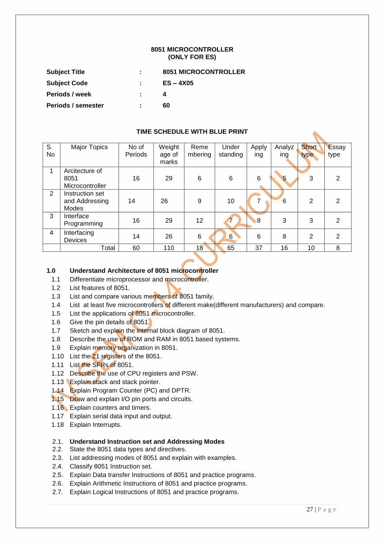
8051 MICROCONTROLLER (ONLY FOR ES)
Subject Title : 8051 MICROCONTROLLER
Subject Code : ES – 4X05
Periods / week : 4
Periods / semester : 60
TIME SCHEDULE WITH BLUE PRINT
S. No
Major Topics No of Periods
Weight age of marks
Reme mbering
Under standing
Apply ing
Analyz ing
Short type
Essay type
1 Arcitecture of 8051 Microcontroller
16 29 6 6 6 5 3 2
2 Instruction set and Addressing Modes
14 26 9 10 7 6 2 2
3 Interface Programming
16 29 12 7 8 3 3 2
4 Interfacing Devices
14 26 6 6 6 8 2 2
Total 60 110 18 65 37 16 10 8
1.0 Understand Architecture of 8051 microcontroller
1.1 Differentiate microprocessor and microcontroller.
1.2 List features of 8051.
1.3 List and compare various members of 8051 family.
1.4 List at least five microcontrollers of different make(different manufacturers) and compare.
1.5 List the applications of 8051 microcontroller.
1.6 Give the pin details of 8051.
1.7 Sketch and explain the internal block diagram of 8051.
1.8 Describe the use of ROM and RAM in 8051 based systems.
1.9 Explain memory organization in 8051.
1.10 List the 21 registers of the 8051.
1.11 List the SFRs of 8051.
1.12 Describe the use of CPU registers and PSW.
1.13 Explain stack and stack pointer.
1.14 Explain Program Counter (PC) and DPTR.
1.15 Draw and explain I/O pin ports and circuits.
1.16 Explain counters and timers.
1.17 Explain serial data input and output.
1.18 Explain Interrupts.
2.1. Understand Instruction set and Addressing Modes
2.2. State the 8051 data types and directives.
2.3. List addressing modes of 8051 and explain with examples.
2.4. Classify 8051 Instruction set.
2.5. Explain Data transfer Instructions of 8051 and practice programs.
2.6. Explain Arithmetic Instructions of 8051 and practice programs.
2.7. Explain Logical Instructions of 8051 and practice programs.

28 | P a g e
2.8. Explain Single bit Instructions of 8051 and practice programs.
2.9. Explain Branching Instructions of 8051 and practice programs.
3.1. Timers, Interrupts and Interface Programming
3.2. Explain the concept of delay and Practice writing delay programs.
3.3. Explain the concept of Timers and its modes of operation.
3.4. Practice programs on Timer interrupt.
3.5. Differentiate interrupts and polling.
3.6. List 6 Interrupts of 8051.
3.7. List the steps in executing an interrupt.
3.8. List the interrupts of the 8051 based on their priority.
3.9. Compare and Contrast Serial versus Parallel Communication.
3.10. Compare synchronous and asynchronous communication.
3.11. Demonstrate 8051 Serial Communication concepts and programming.
3.12. Explain setting baud rate in 8051.
3.13. Program the 8051 to transfer data serially.
3.14. Program the 8051 to receive data serially.
4.0 Interfacing Devices
4.1 Define interfacing.
4.2 Explain the need for interfacing.
4.3 Explain the functional block diagram of 8255.
4.4 Explain the modes of operation of 8255.
4.5 Explain the concept of CWR (Control Word Register) with examples.
4.6 Explain interfacing of 8255 with microprocessor.
4.7 Demonstrate the functional block diagram of 8251.
4.8 Explain interfacing 8251 with microprocessor.
4.9 State the features of 8259.
4.10 Explain the functional block diagram of 8259.
4.11 Explain interfacing 8259 with microprocessor.
4.12 State the features of 8257.
4.13 Explain the functional block diagram of DMA controller 8257.
4.14 Explain interfacing 8257 with microprocessor.
COURSE CONTENTS
1. Understand Architecture of 8051 8051 family features, applications of 8051, Pin details of 8051, Block diagram of 8051, memory organization of 8051, General purpose and SFR registers of 8051, Functions of SP, PSW, PC, DPTR, I/O pin ports, counters, timers and interrupts, Serial data input and output
2. Understand Instruction set and Addressing Modes Data types and directives, addressing modes, data transfer instructions, arithmetic instructions, logical instructions, single bit instructions, branching instructions and programs
3. Timers, Interrupts and Interface Programming Delay and delay programs, timers and their use, interrupts, serial communication, programs on serial communication
4. Interfacing Devices Need for interfacing, Interfacing devices 8255, CWR of 8255, modes of operation of 8255, interfacing with 8255, features, functional block diagram and interfacing of 8251, 8259, 8257

29 | P a g e
Reference Books: 1. 8051 Microcontroller and Applications- Mazdi & Mazdi : 2. The 8051 Microcontroller and Embedded System Muhammad Ali Mazid Janice Gillispie Mazidi 3. Programming and customizing the 8051 Microcontroller -- Myke Predko Intel 8051 datasheet. From www.intel.com 4.The 8051 Microcontroller- Kenneth J Ayala 5.Microprocessor Architecture and Applications- Ramesh S Gaonkar

30 | P a g e

31 | P a g e
CONTROL ENGINEERING
(ONLY FOR IE)
Subject Title : Control Engineering
Subject Code : IE – 4X05
Periods / Week : 4
Periods / Year : 60
TIME SCHEDULE
Sl.
No Major Topics
No. of
Period
s
Weight
age of
Marks
Reme
mber
Underst
and
Applica
tion
Analy
sis
Short
Type
Essay
Type
1
Basic Concept of control
systems and Transfer
functions
10 16 06 10
-
- 2 1
2 Block diagram reduction
techniques 15 26 06 10 10
- 2 2
3
Basic concepts of
process
control
10 16 06 10
- - 2 1
4 Controllers and modes 13 26 03 13 10 - 2 2
5 Digital Controllers and
manufacturing Systems 12 26 06 10 10 - 2 2
Total 60 110 27 53 30 - 10 8
OBJECTIVES
On completion of the following topics the student shall be able to
Understand the basic types of control systems
1.1 Give the importance of control engineering in day to day life and in industry
1.2 Give basic concept of controls and control system.
1.3 Explain open loop and closed loop control system with examples like automatic tank level
control system, room temperature control system, traffic flow control system, etc.
1.4 Distinguish between open loop and closed loop control system
1.5 State the need for feedback in a control system
1.6 Sketch the generalized block diagram of a feedback control system and explain each block
1.7 Explain the following feedback control systems with examples:
a) Linear and Non linear control systems
b) Time variant and time invariant system
c) Continuous data and sampled data system
d) Digital control system
1.8 Define transfer function and explain the use of transfer function in characterizing
a system equation
1.9 State the properties, limitations of a transfer function
1.10 Obtain the relation between transfer function and impulse response of a system
1.11 Derive the closed loop transfer function of the generalised feedback control system
1.12 Explain the voltage current relationships in s-domain for the passive electrical element
1.13 Solve simple problems to obtain transfer function relating to the Electrical systems

32 | P a g e
2.0 Apply the block diagram reduction techniques and Mason’s gain formula for
different linear control systems
2.1 Give the properties of block diagrams- cascade, parallel and canonical forms
2.2 Give the procedure in the reduction of a complicated physical system (blocks in cascade) into
simple block diagram such as:
i) Moving a take off point ahead of/beyond a block
ii) Moving a summing point ahead of/beyond a block
iii) Interchanging two summing points
iv) Removing an element from a forward path
v) Inserting a feed back path
vi) Eliminating a forward loop
Vii) Eliminating a feedback loop
2.3 Solve simple problems on reduction of block diagrams.
2.4 List the rules for construction of Signal flow graphs
2.5 Define Mason‘s gain formula
2.6 Problems on determination of transfer function using signal flow graphs
2.7 Explain time response and frequency response of a control system
2.8 Derive the expression for frequency response of a closed loop system from the transfer
function in s-domain
2.9 Define different types of frequency plots in brief.
2.10 Define stability of a control system
2.11 Explain Routh stability criteria and solve simple problems
UNDERSTAND CONCEPTS OF PROCESS CONTROL
3.0 Introduction to process control
3.1 Define process and process control 3.2 Explain the development of automatic process control with example 3.3 Draw the block diagram of a process control loop 3.4 Describe each element in a process control loop 3.5 Explain batch process and continuous process. 3.6 Define controlled variable, manipulated variable with an example. 3.7 Describe the criteria used to evaluate the response of a process control loop. 3.8 Define process characteristics such as process equation, process load, process lag, and
self regulation. 4.0 Introduction to Controller principles
4.1 Define control system parameters such as error, variable range, control parameter range, control lag, dead time, Cycling
4.2 Classify controller modes as continuous and Discontinuous modes 4.3 Describe two positions, multi position modes. Give examples 4.4 List advantages and disadvantages of two position controller 4.5 Describe proportional control mode 4.6 Define proportional band and offset 4.7 List advantages and disadvantages of proportional controller 4.8 Define integral control mode 4.9 Describe the characteristics of integral control mode 4.10 List advantages and disadvantages of Integral controller 4.11 Describe the derivative control mode 4.12 List advantages and disadvantages of derivative controller 4.13 Describe PI, PD and PID control modes 4.14 List advantages and disadvantages of PI, PD & PID controllers 4.15 Explain the implementation of two-position, P, I, PI, and
PID controller modes using Op- Amps.

33 | P a g e
4.16 Explain the Principle of final control operation. 4.17 Explain need for electric to pressure and pressure to electric converters. 4.18 Explain principle of operation of P/I and I/P converter. 4.19 Explain the following actuators
a) Pneumatic actuator b) Electro pneumatic actuator c) Hydraulic actuator d) Electrical actuator ( solenoid valve and Stepper motor only)
5.0 Digital Controllers and manufacturing Systems
5.1 Explain the role of computers in process control
5.1 Explain the importance of Data Logging.
5.2 Explain the block diagram of Data logging system
5.3 Explain the block diagram of Supervisory control system
5.4 Discuss computer based controller hardware
5.5 Explain Computer manufacturing system.
5.6 Explain pull and push systems
5.7 Explain the Archestra architecture and its components
5.8 Explain concepts of EMI (Enterprise manufacturing Intelligence) and MES (Manufacturing
Execution System)
5.9 Explain the block diagram of modern manufacturing systems.
5.10 Explain concepts of Knowledge based manufacturing systems
COURSE CONTENTS
1.0 Basic Concept of control systems and Transfer functions
Importance of control Engineering, open loop and closed loop control system with
examples, need for feed back , transfer function, features of a feed back, types of
feedback control systems
2.0 Block diagram reduction techniques and Routh’s stability criteria
Impulse response of a system, sample problems on transfer function, reduction of
block diagram, Signal flow graphs, Mason‘s gain formula, time response,
Expression for frequency response, simple problems on Routh‘s criteria
3.0 Basic concepts of process control
Classification of processes, types of process regulation, process variables, need for P & ID
symbols, different elements in the block diagram of a final control operation and the role of
final control element , different types of control elements
4.0 Controllers and modes
Classification of controller modes, working of Electronic controllers, final control element,
actuators,
5.0 Digital controllers ans manufacturing systems: Computers in process control, manufacturing
Systems, Data logging system, EMI (Enterprise manufacturing Intelligence),
REFERENCE BOOKS
1. Control Systems by S.N Verma 2. Control Engineering by Nagarath and Gopal 3. Process Control Instrumentation by Curtis D Johnson 4. Computer Control Of Manufacturing Systems By Koren

34 | P a g e
BIOMEDICAL INSTRUMENTATION
(ONLY FOR BM) Subject Title : Biomedical Instrumentation Subject Code : BM-4X06
Periods Per Week : 04
Periods Per Semester : 60 TIME SCHEDULE
Sl.No Major Topics Periods Weightage of Marks
Short type
Essay type
1. Characteristics of biomedical Instrumentation
12 21 2 1.5
2.
Bio medical Transducers
20 39 3 3
3. Bio potential Electrodes 13 21 2 1.5
4. Amplifiers and Recorders for biomedical applications
15 29 3 2
TOTAL 60 110 10 8
OBJECTIVES On Completion of the course a student will be able to understand: 1.0 Characteristics of bio-medical instrumentation
1.1 Explain general instrumentation system. 1.2 Explain the block diagram of medical instrumentation system. 1.3 Compare a general instrumentation system with a medical instrumentation system 1.4 Explain the constraints while measuring physiological variables 1.5 Define all the general static characteristics of medical instruments like linearity, range,
accuracy, precision, frequency response, stability, signal to noise ratio, hysteresis etc. 1.6 Give physiological signals with their amplitude and frequency ranges.
2.0 Principles and applications of various transducers used in medical equipment.
2.1 Define sensor & transducer 2.2 Classify Transducers. 2.3 Compare sensor and transducer. 2.4 Explain operating principle and applications of variable resistance transducers. 2.5 Explain the principle of strain gauge. 2.6 Derive the gauge factor of strain gauges. 2.7 List the biomedical applications of strain gauges 2.8 Explain the operating principle of variable inductance transducers 2.9 Explain the constructional details, operating principle and applications of an LVDT 2.10 State the need for a phase sensitive detector 2.11 Explain the constructional details, operating principles and applications of variable
capacitance transducers 2.12 Explain the constructional details and operating principles of piezoelectric transducers
and their applications 2.13 Explain the principle of thermocouple 2.14 Give the principle of Seeback and Peltier effect 2.15 State the laws of thermocouple 2.16 Give the principle of thermistor 2.17 Give the resistance temperature relationship of a thermistor

35 | P a g e
2.18 List various optical transducers 2.19 Give the principle of optical transducer-photo-electric, photo conductive, photo voltaic,
photo emissive 3.0 Principles and applications of bio-potential electrodes
3.1 Give the need for a biopotential electrode 3.2 Distinguish between electrode and transducer 3.3 Discuss the significance of electrode-electrolyte interface and electrode skin interface
with equivalent circuit. 3.4 Definition of half-cell potential and its measurement 3.5 Define Offset voltage 3.6 Describe its minimization with Ag-Agcl electrodes with necessary diagram 3.7 List types of electrodes with examples 3.8 Explain types of body surface electrodes 3.9 Explain bio-potential using internal electrodes (needle & wire electrodes)
4.0 Principle and applications of amplifiers used in medical equipment
4.1 Give the requirements of a biopotential amplifier 4.2 Explain the importance of CMMR of bio differential amplifier 4.3 Draw and explain circuit diagram of an instrumentation amplifier (three op-amp
differential amplifier) 4.4 Describe the working of a chopper amplifier with a circuit diagram 4.5 Give the need of a recorder in a measurement system 4.6 List the recorders based on the frequency response 4.7 Explain the working principle of a galvanometric recorder 4.8 Describe Working of an ink jet recorder with necessary diagrams 4.9 Explain the Principle of a thermal recorder 4.10 Explain the use of Significance of CRO in biomedical measurements
COURSE CONTENTS: 1.0 Introduction to Biomedical instrumentation: block diagram general characteristics of
medical instrumentation like linearity range accuracy, precision, frequency response, stability SNR, hysteresis etc. comparison with general instrumentation system important physiological signals & their ranges
2.0 Biomedical transducers: Classification of transducers principles of operation and applications of different types of transducers variable resistance, variable inductance, variable capacitance, piezo-electric, thermistors thermocouples, RTD, optical transducers
3.0 Biopotential electrodes electrode: Electrolyte interface, electrode – skin interface, offset voltage and half-cell potential, equivalent circuit of an electrode principles of operation and applications of surface, needle & wire
4.0 Amplifiers and Recorders for biomedical applications: Operation & applications of operational amplifier, instrumentation amplifier, differential amplifier, chopper amplifier, operation & applications of ink jet recorder, thermal recorders, CRO.
TEXT BOOKS 1. Medical Instrumentation – Application & Design John G. Webster Houghton Mifflin Company 2. Handbook of Biomedical Instrumentation R.S. Khandpur Tata Mc Graw Hill. REFERENCE BOOKS 1. Biomedical Instrumentation Vol I N. Mohan Murali O.U. Press 2. Handbook of Analytical Instruments R.S. Khandpur Tata Mc Graw Hill

36 | P a g e
ELECTROMAGNETIC THEORY (ONLY FOR CN)
Subject Title : Electromagnetic Theory Subject Code : CN – 4X06 Periods / Week : 4 Periods / Year : 60
TIME SCHEDULE WITH BLUE PRINT
Sl. No
Major Topics No. of Period
s
Weightage of
Marks
Short Type
Essay Type
1 Vector Analysis 10 13 1 1
2 Electromagnetic Theory 15 29 3 2
3 Maxwell's Equation 10 13 1 1
4 Plane Wanes & Wave guides
15 29 3 2
5 Wave guide components 10 26 2 2
Total 60 110 10 8
OBJECTIVES On Completion of the course the student will be able to 1.0 Interpret the use of Vector analysis in Electromagnetics 1.1 Define scalars and vectors in vector analysis 1.2 solve simple additions and subtractions of vectors 1.3 Explain Cartesian co-ordinate system using diagrams 1.4 Define component vectors of vector 1.5 Define unit vector 1.6 Explain the concept of a vector field 1.7 Define the dot product and cross product. Give it's applications 1.8 Explain the terms Del, gradient divergence and curl of vector 1.9 Define spherical co-ordinate system, cylindrical co-ordinate system 1.10 Solve some simple problem son gradient, divergence, curl of vectors. 2.0 Understand the basic laws governing Electro magnetics 2.1 Explain Coulomb's law and it's physical interpretation 2.2 Define Electric field intensity, Electric flux density. 2.3 Understand their concepts 2.4 Define Gauss law and prove it 2.5 Explain divergence theorem 2.6 Define potential and potential difference 2.7 Explain potential gradient 2.8 Explain the propertied of conductors and the boundary condition at boundary 2.9 Discuss the nature of pure dielectric materials and the boundary conditions for pure dielectric
materials 2.10 Define Biot-Savart law 2.11 Define Ampere circuit law 2.12 Explain stokes theorem 2.13 Define magnetic flux and magnetic flux density 2.14 Explain the scalar and vector magnetic potential and obtain magnetic boundary conditions at
a boundary 2.15 Solve some simple problems

37 | P a g e
3.0 Understand the concepts of Maxwell's equation 3.1 Explain Faraday's laws 3.2 Explain the concepts of displacement current 3.3 Explain the inconsistency of Ampere's law 3.4 Explain the Maxwell's equation integral from 3.5 Explain the Maxwell's equation in point form 3.6 Give the word statements for the above equations 4.0 Understand the concept of plane waves and guided waves 4.1 Explain uniform plane waves 4.2 Define and illustrate Electromagnetic wave in the space 4.3 Derive the wave equations for free space and for conducting medium 4.4 Explain pointing theorem and pointing vector 4.5 Illustrate power considerations while using pointing theorem 4.6 Explain reflection of plane waves from a perfect conductor 4.7 Explain how waves are guided in a parallel plane wave-guide 4.8 Explain wave propagation in a rectangular wave-guide 4.9 Define modes and dominant mode in a wave-guide 4.10 Compute cut-off wavelength for various modes 4.11 Distinguish between phase velocity and group velocity in a wave-guide 4.12 Derive the relationship between guide wavelength, cut off wavelength and free space
Wavelength of a wave guide 4.13 Derive the characteristics impedance of a rectangular wave-guide for TM and TE modes. 4.14 sketch the electric and magnetic field patterns in dominant mode. 4.15 Describe cavity resonators giving its application. 5.0 Understand the basics of waveguide Components 5.1. Describe the concepts of E-plane & H-plane bends 5.2. Explain the use of corners, tapers and twists 5.3. Explain the wave guide impedance matching elements 5.4. Describe resistive vane and flap attenuators 5.5. Explain the principles of working of tees (E&H)&Hybrid (magic) junctions 5.6. Describe the working principle of directional coupler 5.7. Explain the need of isolators & circulators 5.8. Describe the principle of working of isolator & circulator 5.9. Explain working of microwave filters 5.10. Explain working of microwave mixers 5.11. Describe wave guide coupling methods 5.12. Explain various joints and inter connections in RF transmission lines through RF connection 5.13. List the considerations in leak proof and matching joints

38 | P a g e
COURSE CONTENTS : 1. Vector Analysis :
Scalars and vectors, vector algebra, Cartesian coordinate system, vector components and unit vectors, the vector field, dot product and cross product, introduction to different co-ordinate systems, gradient, divergence and cure in different, co-ordinate system and their physical interpretation.
2. Electromagnetic Theory :
Coulomb's law, Electric field intensity, electric flux and flux density, gauss law divergence theorem, definition of potential difference and potential, potential gradient, conductor properties and boundary conditions, boundary conditions for perfect dielectric materials Biot Savart law, Ampere's circuital law, stokes theorem, magnetic flux and magnetic flux density, scalar and vector magnetic potential and magnetic boundary conditions. 3. Maxwell's Equations : Faraday's law, displacement current, Maxwell's equations in point form and in integral form. 4. Plane Wave and Wave length : Wave equations, uniform plane wave, pointing theorem, pointing vector and power considerations , reflections of plane waves, parallel plane wave guide, introduction to rectangular wave guides, cavity resonance. 5. Waveguide Components : Bends, tapers and twists, attenuators. Hybrid junction, Directional couplers, isolators, circulator, filters and mixers. RF cables, miniaturization by chip components TEXT BOOKS 1. Engineering Electromagnetics - Hayt (Mc graw Hill) 2. Antennas and Wave propagation - K.D. Prasad 3. Electronic Communication System - George Kennedy 4. Electromagnetic Waves & Radiating System - Jordan & Balmain REFERENCE BOOKS 1. Electronic Communications - Roddy & coolen

39 | P a g e
COMPUTER ARCHITECTURE (ONLY FOR CP)
Subject Title : Computer Architecture Subjects Code : CP – 4X06 Periods / Week : 04 Periods / Year : 60
TIME SCHEDULE WITH BLUE PRINT
S. N
o.
Majo
r T
op
ics
No. of
peri
ods
We
ighta
ge
of
Mark
s
Short
Type
Essay T
ype
Rem
em
ber
Unders
tand
App
ly
Ana
lyze
Evalu
ate
Cre
ate
1 Processor and Control Unit Organization 14 26 2 2 6 10
2 Information Representation and Arithmetic Unit
18 34 3 2 1/2 6 23 5
3 Memory Organization and Input – Output Computations
18 34 3 2 1/2 6 23 5
4 High speed computations 10 16 2 1 3 10
TOTAL 60 110 10 8 21 66 10
OBJECTIVES On completion of the course the student will be able to know 1.0 Understand the Processor and Control Unit Organization 1.1 To explain about Accumulator based CPU along with block diagram 1.2 To explain sequential execution of program stored in memory by CPU 1.3 To describe the terms micro-operation, macro operation, fetch cycle, execution cycle & Instruction cycle 1.4 To define opcode, operand. 1.5 To know the Control unit implementation methods. 1.6 To describe about various hardwired control methods 1.7 To understand the micro programmed control-concepts 1.8 To distinguish between micro instruction formats like vertical and horizontal 1.9 To explain the working of micro programmed control-unit Organization 1.10 To explain about the microprogramming sequencing. 2.0 Know the methods of Information representation and Arithmetic Unit 2.1 To list the types of Information representation 2.2 To explain the fixed point representation of numbers with examples 2.3 To explain the floating-point representation of numbers with examples 2.4 To explain the fixed point addition/subtraction along with hardware requirement s and indicate the process through a flow chart. 2.5 To explain fixed point multiplication along with hardware requirement and indicate the
process through a flow - chart 2.6 To explain fixed point division along with hardware implementation and indicate the process
through a flow chart 2.7 To explain floating point addition/subtraction along with the hardware implementation and
indicate the process through a flow-chart 2.8 To explain floating-point multiplication along with the hardware implementation and indicate
the process through a flow chart.

40 | P a g e
2.9 To explain floating-point division along with the hardware implementation & represent the process through a flowchart.
3.0 Memory and Input / Output Organization 3.1 To distinguish between main memory and auxiliary memory. 3.2 To state the need of memory hierarchy. 3.3 To describe about virtual memory principle, address space and memory space 3.4 To describe implementation of virtual memory through Paging and Segmentation. 3.5 To know about high-speed memories like cache, Associative, flash memories 3.6 To describe the concept of Cache memory. 3.7 To describe cache memory mapping schemes like direct, associative and set associative
mapping. 3.8 To explain the associative memory (Content Addressable Memory) 3.9 To explain interleaved memory organization. 3.10 To describe the data transfer modes like programmed I/O, asynchronous and synchronous I/O. 3.12 To explain about Interrupt driven I/O and direct memory access (DMA) 3.14 To understand the organizations of computer with I/O processor. 3.15 To describe communication between CPU and I/O processor. 4.0 High speed Computation 4.1 To state need for high-speed computation 4.2 To give the concept of parallel processing 4.3 To describe about various types of parallel processing 4.2 To explain the principle of pipeline processing 4.5 Advantages of parallel and pipeline processors 4.6 To explain about the multiprocessor systems 4.7 Distinguish between RISC and CISC processors 4.8 To list some contemporary super computers. 4.9 To explain the Architecture of a typical super computer Cray Y-MP. COURSE CONTENTS 1. Processor and Control Unit Organization: Accumulator based CPU, micro and macro operations, control unit implementation methods: Hardwired control, micro programmed control. 2. Information representation and Arithmetic Unit: Information representation, instruction formats, fixed point and floating point addition/subtraction. Multiplication, division: hardware Requirements & algorithms. 3. Memory and. I/O Organization: Memory hierarchy, virtual memory and address mapping schemes, high speed memories: Cache memory and its implementation, associative & interleaved memories. Data transfer modes like programmed I/O, asynchronous and synchronous I/O, I/O processor Organization and communication with CPU. 4. High speed Computation: Parallel processing, pipe line processing & multiprocessor Systems, concepts of RISC and CISC, architecture of super computer. REFERENCE BOOKS 1. Computer System Architecture by M. Morris Mano, PHI 2. Computer Architecture and Organization by John P. Hayes, Mc Graw 2 nd Edition. 3. Advanced Computer Architecture by Kai Hwang, Mc Graw-HIll 4. Structured Computer Organization by Tenenbaum

41 | P a g e
AUDIO ENGINEERING (ONLY FOR EV)
Subject Title : Audio Engineering Subject Code : EV-4X06 Periods per Week : 04 Periods per Semester : 60
TIME SCHEDULE
S.No Major Topics Periods Weightage of marks
A B C D Short
ques
(S)
Essay Ques
(E)
1. Microphones and Loudspeakers
15 26 13 13
2 2
2. Magnetic and Optical recording
15 29 13 13
3 2
3
Signal processing & NRD Studio session procedure
10 16
13 3
2 1
4
Dialogue, effects , music recording, Mixing consoles & Mixing
20 39
3 16 13 10
3 3
TOTAL 60 110 29 55 16 10 10 8
OBJECTIVES On completion of the course the student will be able to know
1.0 Microphones and Loudspeakers
1.1. Define Microphone and classify on the basis of operation 1.2. Explain choice of microphone for location recording 1.3. Explain dynamic, ribbon, condenser microphones 1.4. Compare above Microphones 1.5. Explain Omni, BI, and Uni. directional characteristics of Microphones 1.6. Explain various cardioids polar patterns 1.7. List the specifications of Microphone 1.8. Discuss about microphone impedance, sensitivity open circuit rating, power rating 1.9. List the equipment for location recording 1.10. Discuss about ―NAGARA‖ 1.11. Discuss about synchronization method for picture and sound in film 1.12. Define the term loud speaker and classify on the basis of principle of operation 1.13. Explain the working principle of moving coil speakers 1.14. Define the term resonance, transient response compliance and efficiency of loud speakers. 1.15. Explain the various radiation pattern of loud speakers 1.16. Explain the need of baffles and enclosures 1.17. Explain infinite baffle, open baffle, folded baffle systems 1.18. Discuss about sealed enclosures, vented or bass reflex, tuned port 1.19. Explain about indirect radiators 1.20. Explain radiation characteristics of multicultural horns, acoustic lens and folded horns 1.21. Explain simple cross over network 1.22. Explain multi speaker system 1.23. List the specifications of loud speaker 1.24. Explain the working principle of head phone.

42 | P a g e
2.0 Magnetic & Optical Recording
2.1 Know about history of Magnetic recording & Optical Recording 2.2 Explain basic theory of magnetic recording process 2.3 Draw the hysterics loop and explain 2.4 Draw the tape transfer characteristics 2.5 Explain the various biasing techniques 2.6 Define magnetic properties Coersivity, Retentively, Sensitivity 2.7 Give the description of tape, List the various materials used for tape 2.8 Explain the physical properties and electro-acoustical properties of tape. 2.9 Draw the basic magnetic recorder block diagram
2.10 Explain record head, play back head, eraser head 2.11 Explain equalization process in tape records 2.12 Explain multi-track recording procedure 2.13 Define photographic image and photographic emulsion 2.14 Explain various films used in motion picture industry 2.15 Know the cross section of photographic film (black & white & color) 2.16 Explain variable area and variable density recording system 2.17 Explain sensitometry and densitometry 2.18 Draw the different types of variable area tracks 2.19 Explain the methods of noise reduction in optical recording 2.20 Explain cross modulation and give its importance 2.21 Discuss about process of sound negative processing 2.22 Draw the block diagram of optical recorder and study the controls 2.23 Explain dot by SR in optical 2.24 Introduction to magneto-optical recording
3.0 Signal Processing Devices & Noise reduction devices ( NRDs ), studio session
procedure
3.1 Define the term signal processing and classify on the basis parameter 3.2 Explain about parametric equalizer and graphic Equalizer 3.3 Explain the necessity of HPF, LPF, BPF and notch Filters in signal processing 3.4 Explain the effect of equalization on dynamic range 3.5 Explain the method of controlling dynamic range of a system 3.6 Define compressor and limiter 3.7 Explain the limitations of magnetic tape 3.8 Define noise reduction system and give the applications
a) Classify the NRD and explain with block diagram 3.9 Discuss about burner noise eliminator 3.10 Explain about : (a)Dolby A (b) Dolby B (c)Dolby C (d)Dolby SR 3.11 Discuss about studio session preparation 3.12 Explain recording procedure
3.13 Give the meaning of over dubbing and explain
3.14 Explain self-sync process
3.15 Explain bunching tracks.
3.16 Explain ―PUNCH IN / PUNCH OUT ―Recording
3.17 Explain sound Editing
3.8 Explain mix down procedure
3.19 Know about track laying
4.0 Dialogue, effects , music recording ,Mixing consoles and Mixing
4.1 Give the need for dubbing or post synchronization
4.2 Explain considering points in dialog recording
4.3 Draw the loop dubbing diagram.
4.4 Discuss about diagram pre mixing
4.5 List the various special effects
43 | P a g e
4.6 Know the various special effect sources
4.7 Explain automatic dialog replacement
4.8 Discuss about microphone techniques
4.9 Explain microphone balancing
4.10 Know about music, Discuss about music instruments and their characteristics
4.11 Explain about microphone placements for music instruments
4.12 Explain studio setup for recording
4.13 Explain song recording
4.14 What is back ground music
4.15 List the facilities available in consoles
4.16 Draw the front panel of basic console and explain input, output and monitor sections
4.17 Draw the block diagram of basic consoles
4.18 Discuss about multitrack recording in console
4.19 Compare conventional or split console Vs In-line console
4.20 Know about channel grouping
4.21 Explain EQ section in In-line console
4.22 Explain about console automation
4.23 Discuss about digital console and virtual console
4.24 Study the front panel of any proportional In-line console
4.25 Know about Know about the concept of mixing
4.26 Discuss about studio set up for film mixing
4.27 Mixing for mono, stereo and surround sound
4.28 Give the creative role of engineers in mixing
4.29 Discuss about song mixing
4.30 Explain the transfer of magnetic to optical
4.31 Discuss about final print.
COURSE CONTENTS
1. Microphones and Loud speaker: microphone, NAGARA phiottrack recording
synchronization method for film and sound location recording techniques for different
programme: Types of loud speakers - moving coil, ribbon and electro- radiation pattern of
different loud speakers. Speaker enclosures system, infinite baffle, folded baffle. Sealed
enclosures, bass reflex horn speakers and radiation characteristics, driver units multispeakers
system cross over network- head Phones
2. Magnetic Recording & Optical Recording : Simple disc recording / reproduction chain,
magnetization characteristics. Magnetic material, magnetic recording principle, bias,
longitudinal perpendicular longitudinal transverse recording, magnetic reproduction recorder,
degaussing or bulk eraser multi track recording and mono recording tape manufacturing.
Recorder alignment. Variable density recording, variable area recording, photo graphic
image, D log E curves, developer for sound film, densitometer, sensitometer, gamma, general
working of a lab processor types of variable area, noise reduction, Dolby standards in optical
rewarding, block diagram of WESTREX optical recorder distortions and there causes of
removed magneto optical recordings.
3. Signal Processors & Noise Reduction Devices (NRDs) : Equalizers Filters, compressor,
limiter, expanders, reverberations units, delay units, special effects. Effect of noise in audio
equipment tape limitations, classification of NRD s Dolby systems, DBX, burner noise
elimination and filter.

44 | P a g e
Studio session Procedure : Studio session recording, over dubbing , bounce tracks. Mix
down , editing
4 Dialogue, effects and music recording: need for dubbing, dubbing procedure, quality differences. microphone techniques balancing, music instruments, set up, song recording.
Mixing consoles and mixing : features of console types, split console, inline console, active
combining net works auxiliaries, mixing console groups, automation consoles. concept of
mixing, mixing for macro, releases stereo surround sound, optical transfer release print
REFERENCE BOOKS
1. Audio in media by STANLEY R. ALTEN (I.T.P. Publishing)
2. TAPPLESS SOUND RECORDING by RUMSEY (Focal Press)
3. Sound for film and TV (Focal Press)

45 | P a g e
REAL-TIME OPERATING SYSTEMS (ONLY FOR ES)
Subject Title : Real-Time Operating Systems Subject Code : ES – 4X06 Periods Per Week : 04 Periods Per Semester : 60
TIME SCHEDULE WITH BLUE PRINT
S. No
Major Topics No. of
periods
Weightage of Marks
Rememberi
ng
Understanding
Applying
Analysing
Short Qns
Essay Qns
1 Introduction to Real-Time Operating Systems
15 26 10 10 - 6 2 2
2 More Operating System Services.
15 29 10 10 6 3 3 2
3 Inter Process Communication
15 29 10 10 3 6 3 2
4 Embedded Linux System.
15 26 10 10 3 3 2 2
Total 60 110 40 40 12 18 10 8
1.0 Introduction to Real-Time Operating Systems (RTOS):
1.1 List various operating systems .
1.2 State the functions provided by operating system
1.3 Explain the layered structure of operating system
1.4 State kernel services in an operating system
1.5 State the special requirements of RTOS
1.6 Explain the services offered by RTOS
1.7 Discuss the architecture of Kernel
1.8 Explain tasks and task states
1.9 Explain the meaning of context
1.10 Discuss context switching
2.0 Examine more operating system services
2.1 Explain about scheduling
2.2 Give different scheduling Algorithms
2.3 Compare pre-emptive and non preemptive multi-tasking
2.4 Explain cyclic scheduling.
2.5 Discuss scheduling management for multiple tasks by an RTOS.
2.6 Discuss scheduling multiple tasks by an RTOS in real time.
2.7 Discuss shared data problems.
2.8 Explain different ways to protect shared data.
2.9 Discuss priority inversion problem and the solution using priorty inheritance
2.10 Discuss task synchronisation and resource synchronisation.
3.0 Inter process communication
3.1 Explain inter process communication using
a) Semapores : Explain binary semaphores, Counting semaphores and Multiple
semaphores.
b) Explain the use of semaphore for the critical section of a task.
c) Explain the use of Mutex
d) Discuss the features of Mailboxes, message queue and pipes as an IPC.
e) Explain Events , Signals and Timers in IPC.
3.2 Explain critical section of code.
3.3 Explain deadlocks.

46 | P a g e
3.4 Explain deadlock prevention methods.
3.5 Explain recovering from the dead locks.
3.6 Explain memory management in RTOS
3.7 Explain about interrupt latency.
3.8 Discuss interrupt routines in RTOS environment.
4.0 Embedded Linux System
4.1 List various real time operating systems.
4.2 Give features of various real time operating systems.
4.3 Give the benefits Embedded linux over properaitary embedded operating systems.
4.4 Explain linux kernel architecture.
4.5 List the difference embedded linux and desktop linux.
4.6 Illustrate Embedded linux distribution.
4.7 Describe the architecture of embedded linux.
4.8 Compare the architecture of traditional RTOS and embedded linux.
4.9 Explain the linux start-up sequence
4.10 Describe GNU cross platform tool chain.
4.11 Discuss application porting road map from an RTOS to Embedded linux.
1. Introduction to Real-Time Operating Systems:
Introduction to Real-Time Operating Systems, functions, structure of Operating system,
kernel of OS ,Tasks and States.
2. More operating system services
Processor management Scheduling, Different scheduling algorithms, , Issues related to
shared data, priority inversion problem and the solution using priorty inheritance,
synchronisation and resource synchronisation .
3. Inter process communication :
Semaphores : variants and problems, Messages, Queues, Timer functions, Events,
critical section , dead locks, Interrupt latency, interrupt routines,.
4. Embedded Linux System:
various real time operating systems, features of various real time operating systems ,the
benefits Embedded linux over properaitary embedded operating systems, linux kernel
architecture, the difference embedded linux and desktop linux. , Embedded linux
distribution, the architecture of embedded linux., the linux start-up sequence , GNU
cross platform tool chain, Discuss application porting road map from an RTOS to
Embedded linux.
TEXT BOOKS
1. An Embedded Software Primer – David E. Simon
2. Embedded Systems – Raj Kamal (TMH) 3. Embedded/Real time systems concepts ,design and programming – Dr. K.V.K.K.
Prasad.
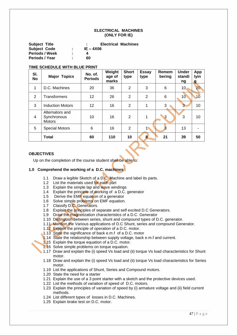
47 | P a g e
ELECTRICAL MACHINES (ONLY FOR IE)
Subject Title : Electrical Machines Subject Code : IE – 4X06 Periods / Week : 4 Periods / Year : 60 TIME SCHEDULE WITH BLUE PRINT
Sl. No
Major Topics No. of.
Periods
Weightage of marks
Short type
Essay type
Remembering
Understandi
ng
Applying
1 D.C. Machines 20 36 2 3 6 10 20
2 Transformers 12 26 2 2 6 10 10
3 Induction Motors 12 16 2 1 3 3 10
4 Alternators and Synchronous Motors
10 16 2 1 3 3 10
5 Special Motors 6 16 2 1 3 13 -
Total 60 110 10 8 21 39 50
OBJECTIVES
Up on the completion of the course student shall be able to:
1.0 Comprehend the working of a D.C. machines :
1.1 Draw a legible Sketch of a D.C. Machine and label its parts. 1.2 List the materials used for each part 1.3 Explain the simple lap and wave windings 1.4 Explain the principle of working of a D.C. generator 1.5 Derive the EMF equation of a generator 1.6 Solve simple problems on EMF equation. 1.7 Classify D.C. Generators. 1.8 Explain the principles of separate and self excited D.C Generators. 1.9 Draw the magnetization characteristics of a D.C. Generator 1.10 Distinguish between series, shunt and compound types of D.C. generator. 1.11 Mention the Various applications of D.C Shunt, series and compound Generator. 1.12 Explain the principle of operation of a D.C. motor. 1.13 State the significance of back e.m.f of a D.C. motor 1.14 State the relationship between supply voltage, back e.m.f and current. 1.15 Explain the torque equation of a D.C. motor. 1.16 Solve simple problems on torque equation. 1.17 Draw and explain the (i) speed Vs load and (ii) torque Vs load characteristics for Shunt
motor. 1.18 Draw and explain the (i) speed Vs load and (ii) torque Vs load characteristics for Series
motor. 1.19 List the applications of Shunt, Series and Compound motors. 1.20 State the need for a starter 1.21 Explain the use of a 3 point starter with a sketch and the protective devices used. 1.22 List the methods of variation of speed of D.C. motors. 1.23 Explain the principles of variation of speed by (i) armature voltage and (ii) field current
methods. 1.24 List different types of losses in D.C. Machines. 1.25 Explain brake test on D.C. motor.

48 | P a g e
1.26 Explain the efficiency, maximum efficiency and maximum output of D.C. machines (generator & motor).
1.27 Solve simple problems on efficiency. 2.0 Comprehend the working of Transformers :
2.1 Explain the constructional features of a 1-Φ transformer. 2.2 State the types of 1-Φ transformers. 2.3 Explain the principle of working of a 1-Φ transformer. 2.4 Derive the EMF equation of a 1-Φ transformer. 2.5 Solve problems on EMF equation. 2.6 State the various losses in a 1-Φ transformer. 2.7 Explain O.C and S.C tests on a 1-Φ transformer. 2.8 Define efficiency of a transformer 2.9 Derive the condition for maximum efficiency of a 1-Φ transformer. 2.10 Solve problems on efficiency. 2.11 Explain the theory of 3-phase transformer. 2.12 List and show the connections of 3-phase transformer. 2.13 Explain the working of (i) Auto transformer (ii) instrument transformers (a) C.Ts and (b) P.Ts).
3.0 Comprehend the working of Induction Motors: 3.1 Describe the constructional details of cage type and wound rotor type Induction motor. 3.2 Illustrate the theory of production of rotating magnetic field. 3.3 Describe the principle of operation of a three phase Induction motor. 3.4 List the advantages and disadvantages of three phase Induction motor. 3.5 Define Slip of an induction motor 3.6 Give the relation between rotor frequency and slip. 3.7 Give the torque equation and explain slip-torque characteristics curves of an induction
motor (no derivation). 3.8 State various losses of an Induction motor. 3.9 Give the condition for maximum efficiency of an Induction motor (no derivation). 3.10 Solve problems on output power. 3.11 Explain the necessity of a starter. 3.12 Sketch various types of starters (D.O.L. & Star-Delta) used . 3.13 List the applications of Induction motors. 3.14 Explain the working principle of a single phase Induction motor. 3.15 Sketch the circuit diagrams for capacitor start and capacitor run motor.
4.0 Comprehend the working of Alternators and Synchronous Motors: 4.1 Explain the construction details of alternators. 4.2 Describe the basic principle of an alternator. 4.3 Define (i) Pitch factor,(ii) Distribution factor of the armature winding. 4.4 Derive the EMF equation of an alternator. 4.5 Solve problems on EMF equation. 4.6 Explain the terms (i)Synchronous impedance and (ii) Voltage regulation of an alternator. 4.7 Explain the principles of operation of a synchronous motor. 4.8 Mention the methods of starting a synchronous motor. 4.9 List the applications of a synchronous motor.
5.0 Comprehend the working of Special Type Motors
5.1 Explain the principle of working of a) Universal motor
b) Stepper motor c) Repulsion motor d) Shaded pole motor
5.2 List the applications of special motors

49 | P a g e
COURSE CONTENTS:
1 Comprehend the working of D.C. Machines ; Introduction, energy conversion , D.C Generator,
principle of working ,simple loop generator, construction details of D.C Machine and materials used
for the above said parts, simple lap and wave windings, uses of lap and wave windings, Expression
for the EMF generated, simple problems, different types of D.C. Generators with diagrams, brush
contact drop, calculation of generated E.M.F, different types of losses, calculation of efficiency,
condition for maximum efficiency ,Magnetization characteristics, Load characteristics of shunt, series
and compound generators. Principle of operation of D.C. Motor, back EMF and speed equation.
Expression for torque developed, characteristics of D.C. series, shunt and compound motors, Need of
a starter, 3-point starter. Speed control by variation of armature voltage and excitation. Calculation of
efficiency from brake test on motors, condition for maximum efficiency and maximum output,
problems.
2 Comprehend the working of Transformers : Working principle, construction of core and
shell type transformers, expressions for the EMF induced in transformer, transformation ratio, voltage
regulation and losses in a transformer, O.C and S.C. tests, calculation of efficiency and voltage
regulation from the O.C. and S.C. test results. Condition for maximum efficiency and output at
maximum efficiency. 3-phase transformers (connections), working of Auto transformer, Instrument
transformers (C.Ts and P.Ts)
3 Comprehend the working of Induction Motors: General principle, Constructional features of a
cage type and wound rotor type induction motors. Production of rotating magnetic field. Slip and
synchronous speed, torque-slip characteristics, power stages, efficiency and condition for maximum
efficiency, problems, types of starters, wiring diagrams of D.O.L., star-delta starters, applications.
Single phase motors, Principle of working of capacitor start and capacitor run Induction motors.
4. Comprehend the working of a Alternators and Synchronous Motors: Basic working principle,
parts, types (salient pole and non-salient pole machines) E.M.F. equation, problems, voltage
regulation, Synchronous impedance, Operation of synchronous motor, methods of starting of
synchronous motors , applications.
5. Comprehend the working of Special Type Motors: Basic working principles of Universal motors,
Stepper motor, shaded pole motor, Repulsion motor and their applications.
REFERENCE BOOKS
1, Electrical Technology vol.-II, B.L. Theraja
2. Electrical and electronic measuring instruments A.K. Sahney
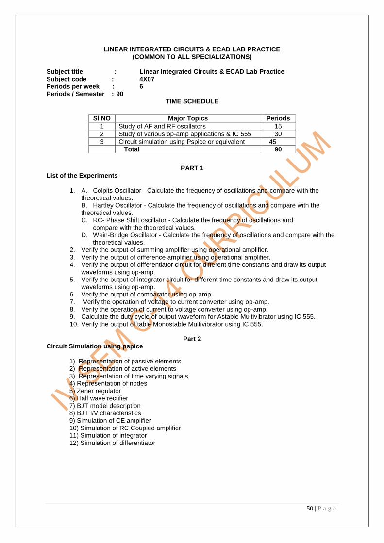
50 | P a g e
LINEAR INTEGRATED CIRCUITS & ECAD LAB PRACTICE (COMMON TO ALL SPECIALIZATIONS)
Subject title : Linear Integrated Circuits & ECAD Lab Practice Subject code : 4X07 Periods per week : 6 Periods / Semester : 90
TIME SCHEDULE
PART 1
List of the Experiments
1. A. Colpits Oscillator - Calculate the frequency of oscillations and compare with the theoretical values. B. Hartley Oscillator - Calculate the frequency of oscillations and compare with the theoretical values. C. RC- Phase Shift oscillator - Calculate the frequency of oscillations and compare with the theoretical values. D. Wein-Bridge Oscillator - Calculate the frequency of oscillations and compare with the
theoretical values. 2. Verify the output of summing amplifier using operational amplifier. 3. Verify the output of difference amplifier using operational amplifier. 4. Verify the output of differentiator circuit for different time constants and draw its output
waveforms using op-amp. 5. Verify the output of integrator circuit for different time constants and draw its output
waveforms using op-amp. 6. Verify the output of comparator using op-amp. 7. Verify the operation of voltage to current converter using op-amp. 8. Verify the operation of current to voltage converter using op-amp. 9. Calculate the duty cycle of output waveform for Astable Multivibrator using IC 555. 10. Verify the output of table Monostable Multivibrator using IC 555.
Part 2
Circuit Simulation using pspice
1) Representation of passive elements 2) Representation of active elements 3) Representation of time varying signals 4) Representation of nodes 5) Zener regulator 6) Half wave rectifier 7) BJT model description 8) BJT I/V characteristics 9) Simulation of CE amplifier 10) Simulation of RC Coupled amplifier 11) Simulation of integrator 12) Simulation of differentiator
Sl NO Major Topics Periods
1 Study of AF and RF oscillators 15
2 Study of various op-amp applications & IC 555 30
3 Circuit simulation using Pspice or equivalent 45
Total 90

51 | P a g e
Exp No
Name of the Experiment
Objectives Key competencies
1 Collipitts,Hartley,wein bridge,RC phase shift oscillator
1. Able to identify the transistor ,feed back circuit 2. Able to read the circuit connections 3. Able to identify the suitable adaptor for the kit 4. Able to connect the adaptor to the kit 5. Able to calculate the theoretical frequency from the circuit 6. Able to set the CRO(getting DC baseline) 7. Able to know the procedure
1. Able to get the sine output in CRO 2. Able to compare theoretical and practical values 3. Writing the reports 4. Draw the graph
2 Summing amplifier using op-amp
1. Identify the suitable op-amp 2. Identify the input output pins of op-amp 3. Able to identify the suitable adaptor for the kit 4. Able to read the circuit connections 5. Able to give the inputs 6. Able to use multi meters
1. Making circuit connection 2. Able to get the output voltage 3. Compare the theoretical summing values and practical summing values 4. Writing the report 5. Writing the tabular form
3 Difference amplifier using op-amp
1. Op-amp identification 2. To study the circuit connections 3. Able to identify the inverting and non- inverting input of an op-amp 4. Able to apply an input to a suitable terminal 5. Able to use the multi meter in suitable voltage or current range
1. Able to connect as per the circuit diagram 2. Able to measure output voltage from output 3. To write the procedure
4 Differentiator using op-amp
1. To read the circuit connection 2. Performing the experiment as per procedure 3. able to get the suitable output waveform for a given input signal 4. Observing the variation on the output by varying ―t‖from ‗T‘=RC
1. Able to write the procedure 2. Able to get the output
waveform for different RC values
3. Draw interference from the observed.
5 Integrater using op-amp
1. To read the circuit connection 2. Performing the experiment as per procedure 3. able to get the suitable output waveform for a given input signal 4. Observing the variation on the output by varying ―t‖from ‗T‘=RC
1. Able to write the procedure 2. Able to get the output waveform for different RC values 3. draw interference from the observed
6 Comparator using op-amp
1. Performing the experiment as per the procedure 2. Able to give input voltages to read the comparison 3. Able to observe waveform on CRO 4. Know the purpose of CRO
1. Able to write procedure 2. Able to compare different inputs. 3. Draw inference from the observed waveform
7 Voltage to current converter and current to voltage converter using op-amp
1. To know the use of op-amp for converting current to voltage and voltage to current 2. Able to make circuit connections 3. Able to select suitable ranges of voltages and currents using multi meters
1. Able to understand the equivalent values of current for the voltage or voltage for the current 2. Verify the output with a suitable relation 3. Able to write the report

52 | P a g e
8 Astable multi vibrator IC555
1. Familiarize with 555 pin configuration 2. Performing the experiment as per the procedure 3. Observing the waveforms on CRO 4. Observing the effect of changing R,C component values 5. Observe waveforms at pins 2,3&5 6. Observe the effect of applying a voltage to pin5 7. Observe the effect of connecting pin4 to ground
1. Draw inference from the observed waveforms 2. Able to write the procedure 3. Able to calculate the duty cycle
9. Monostable multivibrator using IC555
1. Familiarize with 555 pin configuration 2. Performing the experiment as per the procedure 3. Observing the waveforms on CRO 4. Observing the effect of changing R,C component values 5. Observe waveforms at pins 2,3&5 6. Observe the effect of applying a voltage to pin5 7. Observe the effect of connecting pin4 to ground
1. Draw inference from the observed waveforms 2. Able to write the procedure 3. Able to calculate the duty cycle
PART B
10 Representation of passive elements
a) Familiarity with computer operation b) Familiarity with pspice interface c) Defining circuit parameters d) Modelling the circuit e) simulating the circuit f) Observing and interpreting results g) Saving the files
Using Pspice for circuit simulation
11 Representation of active elements
a) Familiarity with computer operation b) Familiarity with pspice interface c) Defining circuit parameters d) Modelling the circuit e) simulating the circuit f) Observing and interpreting results g) Saving the files
Using Pspice for circuit simulation
12 Representation of time varying signals
a) Familiarity with computer operation b) Familiarity with pspice interface c) Defining circuit parameters d) Modelling the circuit e) simulating the circuit f) Observing and interpreting results g) Saving the files
Using Pspice for circuit simulation
13 Representation of nodes
a) Familiarity with computer operation b) Familiarity with Pspice interface c) Defining circuit parameters d) Modelling the circuit e) simulating the circuit f) Observing and interpreting results g) Saving the files
Using Pspice for circuit simulation
14 Zener regulator a) Familiarity with computer operation b) Familiarity with Pspice interface c) Defining circuit parameters d) Modelling the circuit e) simulating the circuit f) Observing and interpreting results g) Saving the files
Using Pspice for circuit simulation
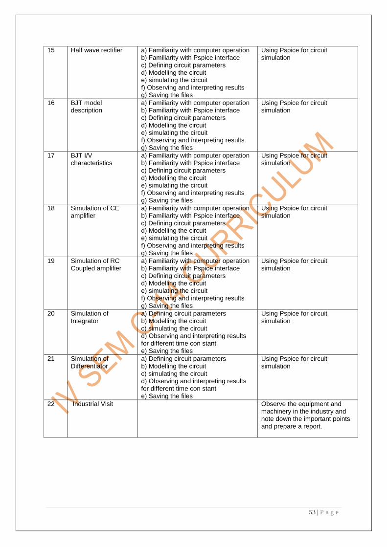
53 | P a g e
15 Half wave rectifier a) Familiarity with computer operation b) Familiarity with Pspice interface c) Defining circuit parameters d) Modelling the circuit e) simulating the circuit f) Observing and interpreting results g) Saving the files
Using Pspice for circuit simulation
16 BJT model description
a) Familiarity with computer operation b) Familiarity with Pspice interface c) Defining circuit parameters d) Modelling the circuit e) simulating the circuit f) Observing and interpreting results g) Saving the files
Using Pspice for circuit simulation
17 BJT I/V characteristics
a) Familiarity with computer operation b) Familiarity with Pspice interface c) Defining circuit parameters d) Modelling the circuit e) simulating the circuit f) Observing and interpreting results g) Saving the files
Using Pspice for circuit simulation
18 Simulation of CE amplifier
a) Familiarity with computer operation b) Familiarity with Pspice interface c) Defining circuit parameters d) Modelling the circuit e) simulating the circuit f) Observing and interpreting results g) Saving the files
Using Pspice for circuit simulation
19 Simulation of RC Coupled amplifier
a) Familiarity with computer operation b) Familiarity with Pspice interface c) Defining circuit parameters d) Modelling the circuit e) simulating the circuit f) Observing and interpreting results g) Saving the files
Using Pspice for circuit simulation
20 Simulation of Integrator
a) Defining circuit parameters b) Modelling the circuit c) simulating the circuit d) Observing and interpreting results for different time con stant e) Saving the files
Using Pspice for circuit simulation
21 Simulation of Differentiator
a) Defining circuit parameters b) Modelling the circuit c) simulating the circuit d) Observing and interpreting results for different time con stant e) Saving the files
Using Pspice for circuit simulation
22 Industrial Visit Observe the equipment and machinery in the industry and note down the important points and prepare a report.

54 | P a g e
COMMUNICATION SKILLS LAB PRACTICE
(COMMON TO ALL SPECIALIZATIONS)
Subject title : Communication skills Lab Practice
Subject code : 4X08
Periods per week : 3
Periods per semester : 45
Introduction :
In the context of globalization , competence in speaking skills is the need of the hour The gap
between the needs of the industry and the curriculum can be bridged by enabling the students to
hone their speaking and listening skills. This course aims at providing opportunities for practicing
speaking.
TIME SCHEDULE
Objectives :
On completion of the course the students will be able to
Strengthen their listening skills
Strengthen their speaking skills
Sno. Topic Periods Weightage of marks
(End Exam )
Sessional
marks
Total
1 Listening I 3
10
10
2 Listening II 3 20
3 Introducing oneself 3
50
30
80
4 Describing objects 3
5 Describing events 3
6 Reporting past incidents 3
7 Speaking from observation /
reading 3
8 JAM 6
9 Group discussion 6
10 Mock interviews 6
11 Making presentations 6
45 60 40 100

55 | P a g e
Competencies and key competencies to be achieved by the student
Communicative methodology (CLT) should be used to create an interactive class. Apart from the suggestions given teachers are free to innovate to use any activity to improve the language competence of students . Attention can also be given to improve the accent and intonation of students. Note: * This subject is a theory subject. ** The workload should be calculated as theory workload. ***Examinations in the subject will be treated as a practical one.
Topic Teacher’s input/ methodology Students competence
Listening I
Listening II
Pre- Listening –eliciting, pictures
While - Listening
Post –Listening –project , writing
Identifying the main idea,
Identifying specific details,
Identifying parallel and contradictory ideas
Drawing inferences,
Reasoning
Introducing
oneself
Kinds of introduction --official/
personal, dynamic vocabulary,
Body language, Model introduction,
Use of line ups
Use of simple present tense,
Sequencing,
Appropriate vocabulary
Reporting
incidents
Group work /pair work,
Elicit,
Use of past tense,
Student presentations
Use of past tense,
Relevant vocabulary
Describing
objects
Vocabulary ,
Use of adjectives,
Games—I spy,
Group presentations
Use of adjectives,
Dimensions,shapes
Compare and contrast,
sequence
Describing
events
Group work/pair work
Use of appropriate tense
Use of appropriate tense,
sequencing
Reporting past
incidents
Use of past tense,
Vocabulary
Student presentations
Use of past tense , sequencing
Speaking from
observation/rea
ding
Group work/pair work,
Reading techniques ,
Use of past tense,
Summarising , evaluating, comprehension
JAM Effective techniques ,
Good beginning , conclusion, tips,
Use of line ups
Vocabulary,
Sequencing,
Fluency,
Thinking spontaneously
Group
discussion
Expressing opinion, body language,
Expressing opinion, agree/ disagree,
fluency,Persuasive and leadership skills
Mock interview FAQs , body language Role play, body language,
Making
presentations
Student presentations Using charts , pictures, interpreting data,
sequencing,PPTs

56 | P a g e
PULSE & DIGITAL CIRCUITS LAB PRACTICE COMMON TO CN/BM/EV/ES (EXCEPT CP & IE)
Subject Title : Pulse & Digital Circuits Lab Practice Subject Code : BM/CN/EV/ES-4X09 Periods/Week : 03 Periods/Semester : 45
LIST OF EXPERIMENTS List of Experiments 1. To realize clippers and observe the waveforms on CRO A) Study about the function generator using IC‘s 8038 & 566 B) Realize series and parallel clippers C) Assemble positive and negative clipper circuits D) Connect two diodes back to back and apply an AC signal from function generator and observe the waveform on CRO. Draw the inference. E) Connect a Zener diode in place of a diode and measure the output voltage with DMM and also observe the waveform on CRO F) Construct a clipper using transistor and op-amp and observe the output waveform on CRO 2. To realize clampers and observe the waveforms on CRO Construct a clamper using diode, transistor and op-amp and observe the output waveform on CRO 3. To realize wave shaping circuits A) Observe and determine rise time, fall time and duty cycle of a pulse B) Vary duty cycle of a Square wave to the desired value using function generator on CRO C) Implement differentiator using RC elements for a given time constant D) Demonstrate pulse generation using differentiator circuit E) Demonstrate the use of differentiator circuit as a high pass filter F) Implement Integrator using RC elements for a given time constant G) Demonstrate pulse generation using integrator circuit H) Demonstrate the use of integrator circuit as a low pass filter 4. Multivibrators A) Construct an Astable multivibrator using transistor and op-amps and calculate the duty cycle of the output waveform B) Construct a Bistable multivibrator using transistor and op-amps and calculate Ton and Toff of the output waveform C) Construct a Monostable multivibrator using transistor and op-amps and measure the pulse width of the output waveforms generated D) Determine the LTP and UTP for a Schmitt trigger using op-amps E) Adjust the UTP and LTP to the desired value for a Schmitt trigger circuit F) Use the Schmitt trigger circuit for battery charge
S. No.
Major Topics No. of
Periods
I. CLIPPER & CLAMPER CIRCUITS 12
II WAVE SHAPING CIRCUITS 06
III MULTIVIBRATORS 12
IV LOGIC FAMILIES 09
V MEMORIES 06
Total 45

57 | P a g e
5. Logic Families A) Identify different TTL and CMOS IC‘s B) Study the characteristic parameter of TTL and CMOS IC‘s using data sheet and compare them. C) Study the positive and negative logic family IC‘s using data sheets D) Demonstrate the interfacing of TTL and CMOS IC‘s E) Demonstrate the interfacing op-amp with digital IC‘s using comparator 6. Experiments with memories A) Identify the various memories IC‘s and note their pin configuration from the data sheet RAM, ROM, EPROM, EEPROM LIST OF EXPERIMENTS, OBJECTIVES & COMPETENCIES
Exp No Name of the Experiment Objectives Key Competencies
I CLIPPER & CLAMPER CIRCUITS
A) Usage of function generator
B) Obtain the output waveform for biased and unbiased clipper and clamper circuits
1.Measuring frequencies and amplitudes of various signal using function generator 2. Assembling the circuit and testing with proper bias. 3. Observing the waveforms and drawing inference. 4. Use the clipper and clamper circuits in the projects
II WAVE SHAPING CIRCUITS
A) Designing of high pass circuits and observe for different time constants and draw it‘s output waveforms (using passive components) B) Understand how and when a HPF act like a differentiator circuit C) Designing of low pass circuits and observe for different time constants and draw it‘s output waveforms (using passive components)
D) Understand how and when a LPF act like an integrator circuit
1.Assembling the circuit and testing with proper bias. 2.Understand the relation between the output waveforms and time constant. 3.Applications of integrator and differentiator circuits
III MULTIVIBRATORS
A) Calculate the duty cycle of the output waveform for an Astable Multivibrator using transistors B) Calculate the Ton and Toff of a Bistable Multivibrator using transistors C) Draw the O/P waveforms and obtain the pulse width of a monostable Multivibrator using transistors. D) Draw the output waveforms and obtain the LTP & UTP for a schmitt trigger using transistors.
1.Able to identify the appropriate kit 2. Able to identify the available Components on the kit for each experiment 3. Able to read the connections 4. Able to observe the output of the circuit 5. Able to draw output waveforms 6. Usage of multivibrators in switching applications

58 | P a g e
IV LOGIC FAMILIES
a) Identification of different TTL & CMOS ICs b) Understand the characteristic parameters of TTL & CMOS ICs using data sheets and compare them c) Understand positive and negative logic family ICs using data sheets d) Interfacing TTL & CMOS ICs e) Demonstrate the interfacing of Op-amp with digital ICs using comparators
1.Identification of ICs of different logic families and knowing their characteristics. 2.Understanding the suitability for different applications 3. Interfacing of different IC families.
V MEMORIES
To Identify Various Memory ICs and Note their pin Configuration from the datasheets a) RAM b) ROM c) EPROM d) EEPROM
1. Identification of ICs of different logic families and knowing their characteristics. 2.Understanding the suitability for different applications

59 | P a g e
MICROPROCESSORS LAB PRACTICE AND PULSE AND DIGITAL CIRCUITS LAB PRACTICE
(COMMON TO CP/IE)
SUBJECT TITLE : (A) MICROPROCESSORS LAB PRACTICE (B) PULSE AND DIGITAL CIRCUITS LAB PRACTICE
SUBJECT CODE : CP/IE-4X09 A, B PERIODS/WEEK : 06 PERIODS/SEMESTER : 90
A) MICROPROCESSORS LAB PRACTICE
TIME SCHEDULE
LIST OF EXPERIMENTS
1. Working with microprocessor trainer kits and usage of MASM or TASM assembler software on computer system.
a) Familiarization of 8086 Microprocessor trainer Kit and its usage b) Demonstration of implementing the program on the trainer kit, data implementation, execution
and verification of the result. c) Familiarization of Desk top Computer system using either MASM or TASM assembler
software. d) Familiarization of software development tools: Editor, assembler, Linker and Debugger e) Demonstration of implementation of the program on EDITOR, assembling the program on
ASSEMBLER, making object file format through LINKER , execution through DEBUGGER and verification of the result
f) Demonstrate the selection of memory location at an address, entering the data in the location and its verification
g) Implement a simple program for demonstration and verify the result through different memory addressing methods
S
S.
No.
Major Topics
EXPERIMENT
N
No. of
Periods
1. Demonstration of Microprocessor trainer kit and Desk Top
Computer system using MASM or TASM
5
2. Simple programs using data transfer, arithmetic, logical and branch
instructions
20
3. Programs using Procedures and parameter passing 10
4. Programs using Interrupts, Monitor or display routines and other
software applications
10
Total 45

60 | P a g e
2. Practicing simple programs of 8086 a) 1‘s complement and 2‘s complement of 16-bit numbers b) Addition, subtraction, division and multiplication of 16-bit numbers c) BCD addition of decimal data d) Finding the Largest or smallest number from given 8-bit data array e) Arranging the 8-bit data array in Ascending or Descending order f) Conversion of Binary Gray code g) LCM of two 16-bit unsigned numbers h) Factorial of 8-bit data i) Multibyte addition j) Squire root of number k) Separation of even and odd numbers from the given 8-bit data array
l) Evaluation of logical expression 3. Practicing the programs using Procedures and Parameter passing
a) Simple program of adding two numbers using Global data stored in memory Accessible to all modules b) Simple program of using Call by Value and Reference using Stack variables c) Simple program involving passing and returning values using register variables d) Conversion of BCD number to a Binary number e) simple program that uses a CALL lookup table using procedures
4. Practicing the programs using Interrupts, Display routines and other applications a) Displaying the message on the monitor screen with procedure DISP b)Program with a sequence used to call System software that uses parameters stored in stack frame c) Digital software clock List of Experiments, Objectives & Key Competencies
Exp No Name of the Experiment Objectives Key Competencies
1 Demonstration of
Microprocessor trainer kit and
Desk Top Computer system
using MASM or TASM
Familiarization of trainer kit
and Assembler software on
computer system
Observing the software
development tools and
conversion of the
assembling files into others
2 Simple programs using data
transfer, arithmetic, logical
and branch instructions
a) Practicing all assembling language instructions and directives
b) Implementation of the program
c) Providing the data in the respective memory locations
d) Verification of the result.
a) Observing the output and verification of the result with theoretical values
b) Improving programming methodology
3 Programs using
Procedures and
parameter passing
a) Practicing assembling language programs with various procedures and parameters
b) Practice using Stack variables
Identifying the results
through parameter
passing and look up
tables
4 Programs using
Interrupts, Monitor or
display routines and other
software applications
Practice the programs with
advanced concepts
Observe the displaying
the result of messages

61 | P a g e
B) PULSE AND DIGITAL CIRCUITS LAB PRACTICE
TIME SCHEDULE
List of Experiments
1. To realize clippers and observe the waveforms on CRO
A) Study about the function generator using IC‘s 8038 & 566 B) Realize series and parallel clippers C) Assemble positive and negative clipper circuits D) Connect two diodes back to back and apply an AC signal from function generator and observe the waveform on CRO. Draw the inference. E) Connect a Zener diode in place of a diode and measure the output voltage with DMM and also observe the waveform on CRO F) Construct a clipper using transistor and op-amp and observe the output waveform on CRO 2. To realize clampers and observe the waveforms on CRO Construct a clamper using diode, transistor and op-amp and observe the output waveform on CRO 3. To realize wave shaping circuits A) Observe and determine rise time, fall time and duty cycle of a pulse B) Vary duty cycle of a Square wave to the desired value using function generator on CRO C) Implement differentiator using RC elements for a given time constant D) Demonstrate pulse generation using differentiator circuit E) Demonstrate the use of differentiator circuit as a high pass filter F) Implement Integrator using RC elements for a given time constant G) Demonstrate pulse generation using integrator circuit H) Demonstrate the use of integrator circuit as a low pass filter 4. Multivibrators A) Construct an Astable multivibrator using transistor and op-amps and calculate the duty cycle of the output waveform B) Construct a Bistable multivibrator using transistor and op-amps and calculate Ton and Toff of the output waveform C) Construct a Monostable multivibrator using transistor and op-amps and measure the pulse width of the output waveforms generated D) Determine the LTP and UTP for a Schmitt trigger using op-amps E) Adjust the UTP and LTP to the desired value for a Schmitt trigger circuit F) Use the Schmitt trigger circuit for battery charge
S. No. LIST OF EXPERIMENTS No. of
Periods
I. Clipper & Clamper Circuits 12
II Wave Shaping Circuits 06
III Multivibrators 12
IV Logic Families 09
V Memories 06
Total 45

62 | P a g e
5. Logic Families A) Identify different TTL and CMOS IC‘s B) Study the characteristic parameter of TTL and CMOS IC‘s using data sheet and compare them. C) Study the positive and negative logic family IC‘s using data sheets D) Demonstrate the interfacing of TTL and CMOS IC‘s E) Demonstrate the interfacing op-amp with digital IC‘s using comparator 6. Experiments with memories A) Identify the various memories IC‘s and note their pin configuration from the data sheet RAM, ROM, EPROM, EEPROM List of Experiments, Objectives & Competencies
Exp No Name of the Experiment Objectives Key Competencies
I Clipper & Clamper Circuits
C) Usage of function generator
D) Obtain the output waveform for biased and unbiased clipper and clamper circuits
1.Measuring frequencies
and amplitudes of various
signal using function
generator
2. Assembling the circuit and
testing with proper bias.
3. Observing the waveforms
and drawing inference.
4. Use the clipper and
clamper circuits in the
projects
II Wave Shaping Circuits
A) Designing of high pass circuits and observe for different time constants and draw it‘s output waveforms (using passive components) B) Understand how and when a HPF act like a differentiator circuit C) Designing of low pass circuits and observe for different time constants and draw it‘s output waveforms (using passive components)
D) Understand how and when a LPF act like an integrator circuit
1.Assembling the circuit and
testing with proper bias.
2.Understand the relation
between the output
waveforms and time
constant.
3.Applications of integrator
and differentiator circuits

63 | P a g e
III Multivibrators
A) Calculate the duty cycle of the output waveform for an Astable Multivibrator using transistors B) Calculate the Ton and Toff of a Bistable Multivibrator using transistors C) Draw the O/P waveforms and obtain the pulse width of a monostable Multivibrator using transistors. D) Draw the output waveforms and obtain the LTP & UTP for a schmitt trigger using transistors.
1.Able to identify the
appropriate kit
2. Able to identify the
available Components on
the kit for each experiment
3. Able to read the
connections
4. Able to observe the
output of the circuit
5. Able to draw output
waveforms
6. Usage of multivibrators in
switching applications
IV Logic families
a) Identification of different
TTL & CMOS ICs
b) Understand the
characteristic parameters
of TTL & CMOS ICs using
data sheets and compare
them
c) Understand positive and
negative logic family ICs
using data sheets
d) Interfacing TTL &
CMOS ICs
e) Demonstrate the
interfacing of Op-amp with
digital ICs using
comparators
1.Identification of ICs of
different logic families and
knowing their characteristics.
2.Understanding the
suitability for different
applications
3. Interfacing of different IC
families.
V Memories
To Identify Various
Memory ICs and Note their
pin Configuration from the
datasheets
a) RAM b) ROM c) EPROM
d) EEPROM
1. Identification of ICs of
different logic families and
knowing their characteristics.
2.Understanding the
suitability for different
applications

64 | P a g e
MICROPROCESSORS LAB PRACTICE
(COMMON TO BM/CN/EV)
SUBJECT TITLE : MICROPROCESSORSLAB PRACTICE SUBJECT CODE : BM/CN/EV-4X10 PERIODS/WEEK : 06 PERIODS/SEMESTER : 90
TIME SCHEDULE
LIST OF EXPERIMENTS
2. Working with microprocessor trainer kits and usage of MASM or TASM assembler software on computer system.
h) Familiarization of 8086 Microprocessor trainer Kit and its usage i) Demonstration of implementing the program on the trainer kit, data implementation, execution
and verification of the result. j) Familiarization of Desk top Computer system using either MASM or TASM assembler
software. k) Familiarization of software development tools: Editor, assembler, Linker and Debugger l) Demonstration of implementation of the program on EDITOR, assembling the program on
ASSEMBLER, making object file format through LINKER , execution through DEBUGGER and verification of the result
m) Demonstrate the selection of memory location at an address, entering the data in the location and its verification
n) Implement a simple program for demonstration and verify the result through different memory addressing methods
2. Practicing simple programs of 8086 a) 1‘s complement and 2‘s complement of 16-bit numbers b) Addition, subtraction, division and multiplication of 16-bit numbers c) BCD addition of decimal data d) Finding the Largest or smallest number from given 8-bit data array e) Arranging the 8-bit data array in Ascending or Descending order f) Conversion of Binary Gray code g) LCM of two 16-bit unsigned numbers h) Factorial of 8-bit data i) Multibyte addition j) Squire root of number k) Separation of even and odd numbers from the given 8-bit data array l) Evaluation of logical expression
3. Practicing the programs using Procedures and Parameter passing a) Simple program of adding two numbers using Global data stored in memory Accessible to all modules b) Simple program of using Call by Value and Reference using Stack variables c) Simple program involving passing and returning values using register variables d) Conversion of BCD number to a Binary number
SS.
No.
Major Topics
EXPERIMENT
NNo. of
Periods
1. Demonstration of Microprocessor trainer kit and Desk Top Computer system using MASM or TASM
15
2. Simple programs using data transfer, arithmetic, logical and branch instructions
30
3. Programs using Procedures and parameter passing 30
4. Programs using Interrupts, Monitor or display routines and other software applications
15
Total 90

65 | P a g e
e) simple program that uses a CALL lookup table using procedures
4. Practicing the programs using Interrupts, Display routines and other applications a) Displaying the message on the monitor screen with procedure DISP b)Program with a sequence used to call System software that uses parameters stored in stack frame
c) Digital software clock List of Experiments, Objectives & Competencies
Exp No Name of the Experiment Objectives Key Competencies
1 Demonstration of Microprocessor trainer kit and Desk Top Computer system using MASM or TASM
Familiarization of trainer kit and Assembler software on computer system
Observing the software development tools and conversion of the assembling files into others
2 Simple programs using data transfer, arithmetic, logical and branch instructions
e) Practicing all assembling language instructions and directives
f) Implementation of the program
g) Providing the data in the respective memory locations
h) Verification of the result.
c) Observing the output and verification of the result with theoretical values
d) Improving programming methodology
3 Programs using Procedures and parameter passing
c) Practicing assembling language programs with various procedures and parameters
d) Practice using Stack variables
Identifying the results through parameter passing and look up tables
4 Programs using Interrupts, Monitor or display routines and other software applications
Practice the programs with advanced concepts
Observe the displaying the result of messages
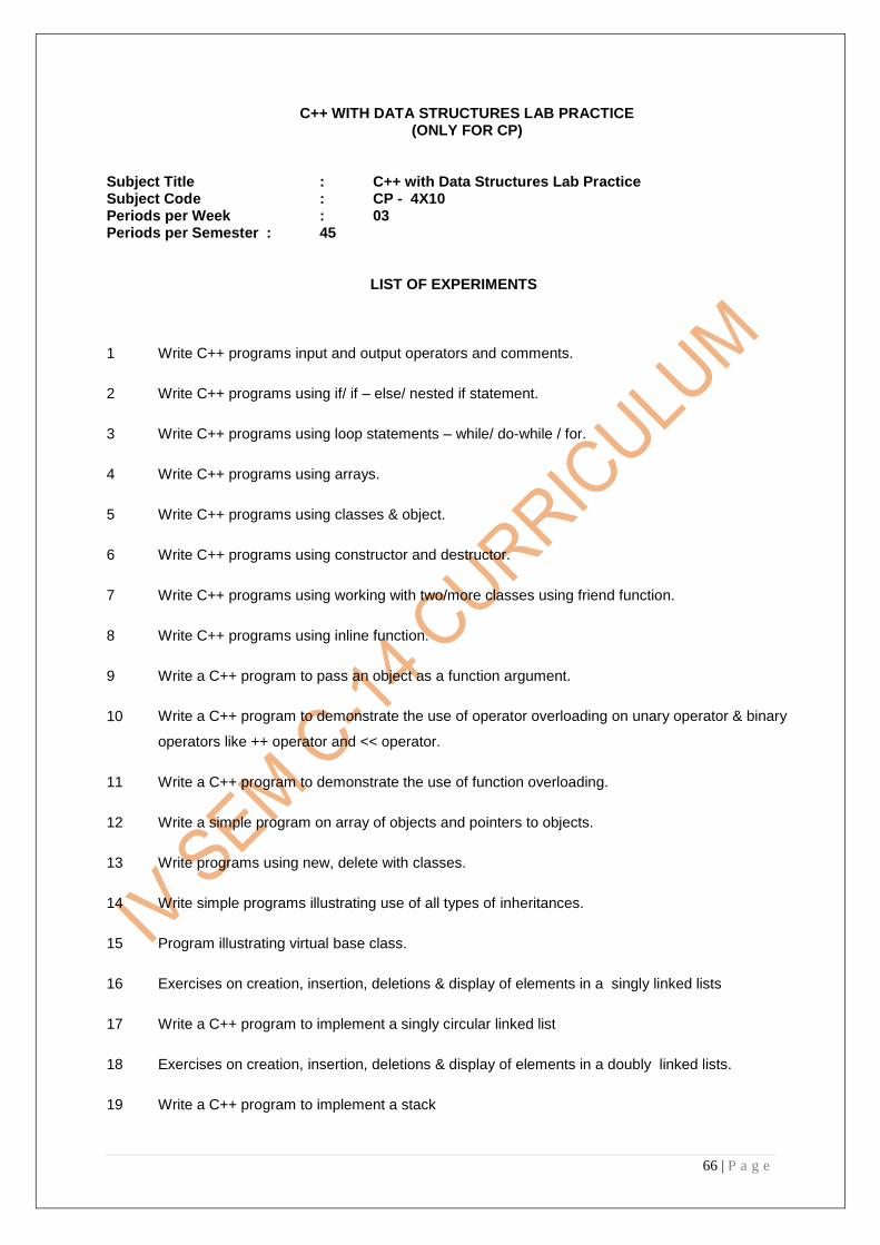
66 | P a g e
C++ WITH DATA STRUCTURES LAB PRACTICE (ONLY FOR CP)
Subject Title : C++ with Data Structures Lab Practice Subject Code : CP - 4X10 Periods per Week : 03 Periods per Semester : 45
LIST OF EXPERIMENTS
1 Write C++ programs input and output operators and comments.
2 Write C++ programs using if/ if – else/ nested if statement.
3 Write C++ programs using loop statements – while/ do-while / for.
4 Write C++ programs using arrays.
5 Write C++ programs using classes & object.
6 Write C++ programs using constructor and destructor.
7 Write C++ programs using working with two/more classes using friend function.
8 Write C++ programs using inline function.
9 Write a C++ program to pass an object as a function argument.
10 Write a C++ program to demonstrate the use of operator overloading on unary operator & binary
operators like ++ operator and << operator.
11 Write a C++ program to demonstrate the use of function overloading.
12 Write a simple program on array of objects and pointers to objects.
13 Write programs using new, delete with classes.
14 Write simple programs illustrating use of all types of inheritances.
15 Program illustrating virtual base class.
16 Exercises on creation, insertion, deletions & display of elements in a singly linked lists
17 Write a C++ program to implement a singly circular linked list
18 Exercises on creation, insertion, deletions & display of elements in a doubly linked lists.
19 Write a C++ program to implement a stack

67 | P a g e
20 Write a C++ program to implement a queue
21 Write a C++ program to create a binary tree & its traversal operations
22 Exercise on Selection sort
23 Exercise on insertion sort
24 Exercise on bubble sort
25 Implement a program for merge sort on two sorted lists of elements
26 Exercises on linear search
27 Write a C++ program on binary search

68 | P a g e
MICROPROCESSORS & MICROCONTROLLERS LAB PRACTICE (ONLY FOR ES)
SUBJECT TITLE : MICROPROCESSORS & MICROCONTROLLERS LAB PRACTICE SUBJECT CODE : ES 4X10 PERIODS/WEEK : 6 PERIODS/SEMESTER: 90 Rationale: Microprocessors & Microcontrollers lab Practice is included in the same semester to ensure continuity and give an opportunity for the students to reinforce their theoretical knowledge by practically verifying in the laboratory. It is mainly intended to implement the programming methodology in assembly language programming
(i) using either Microprocessor Trainer kit or MASM or TASM software on computer system to perform Microprocessors lab
(ii) and also using Microcontroller Trainer kit or RIDE-51 software or Simulator software on computer system to perform Microcontrollers lab.
TIME SCHEDULE
LIST OF EXPERIMENTS
3. Working with microprocessor trainer kits and usage of MASM or TASM assembler
software on computer system.
a. Familiarization of 8086 Microprocessor trainer Kit and its usage
b. Demonstration of implementing the program on the trainer kit, data implementation, execution
and verification of the result.
c. Familiarization of Desk top Computer system using either MASM or TASM assembler
software.
d. Familiarization of software development tools: Editor, assembler, Linker and Debugger
S
S.
No.
Major Topics
EXPERIMENT
N
No. of
Periods
1. Demonstration of Microprocessor trainer kit and Desk Top
Computer system using MASM or TASM 15
2. Simple programs using data transfer, arithmetic, logical and branch
instructions of 8086 30
3. Demonstration of Microcontroller trainer kit and Desk Top
Computer system using RIDE-51/ Simulator 15
4.
Simple programs using data transfer, arithmetic, logical and branch
instructions of 8051
30
Total 90

69 | P a g e
e. Demonstration of implementation of the program on EDITOR, assembling the program on
ASSEMBLER, making object file format through LINKER , execution through DEBUGGER
and verification of the result
f. Demonstrate the selection of memory location at an address, entering the data in the location
and its verification
g. Implement a simple program for demonstration and verify the result through different memory
addressing methods
2. Practicing simple programs of 8086
a) 1‘s complement and 2‘s complement of 16-bit numbers
b) Addition, subtraction, division and multiplication of 16-bit numbers
c) BCD addition of decimal data
d) Finding the Largest or smallest number from given 8-bit data array
e) Arranging the 8-bit data array in Ascending or Descending order
f) Conversion of Binary to Gray code
g) LCM of two 16-bit unsigned numbers
h) Factorial of 8-bit data
i) Multibyte addition
j) Squire root of 8/16 – bit number
k) Separation of even and odd numbers from the given 8-bit data array
l) Evaluation of logical expression
3. Working with microcontroller trainer kits and usage of RIDE-51 or SIMULATOR software
on computer system.
a) Familiarization of 8051 Microcontroller trainer Kit and its usage
b) Demonstration of implementing the program on the trainer kit, data implementation, execution
and verification of the result.
c) Familiarization of Desk top Computer system using either RIDE – 51 / Simulator assembler
software.
d) Familiarization of software development tools: Editor, assembler, Linker and Debugger
e) Demonstration of implementation of the program on EDITOR, assembling the program on
ASSEMBLER, execution through DEBUGGER and verification of the result.
f) Demonstrate the selection of memory location at an address, entering the data in the location
and its verification
g) Implement a simple program for demonstration and verify the result through different memory
addressing methods
4 Practicing simple programs of 8051
a) 1‘s complement and 2‘s complement of 8-bit numbers
b) Addition, subtraction, division and multiplication of 8-bit numbers
c) BCD addition of decimal data
d) Finding the Largest or smallest number from given 8-bit data array
e) Arranging the 8-bit data array in Ascending or Descending order
f) LCM of two 8-bit unsigned numbers
g) Factorial of 8-bit data
h) Squire root of 8 – bit number
i) Separation of even and odd numbers from the given 8-bit data array
j) Evaluation of logical expression

70 | P a g e
List of Experiments, Objectives & Competencies:
Exp
No: Name of the Experiment Objectives Key Competencies
1
Demonstration of
Microprocessor trainer kit and
Desk Top Computer system
using MASM or TASM
Familiarization of trainer kit
and Assembler software on
computer system
Observing the software
development tools and
conversion of the
assembling files into others
2
Simple programs using data
transfer, arithmetic, logical
and branch instructions of
8086
i) Practicing all
assembling language
instructions and
directives
j) Implementation of the
program
k) Providing the data in the
respective memory
locations
l) Verification of the result.
e) Observing the output
and verification of the
result with theoretical
values
f) Improving
programming
methodology
3
Demonstration of
Microcontroller trainer kit and
Desk Top Computer system
using RIDE-51 or Simulator
Familiarization of trainer kit
and Assembler software on
computer system
Observing the software
development tools and
conversion of the
assembling files into
others
4
Simple programs using
data transfer, arithmetic,
logical and branch
instructions of 8051
a)Practicing all
assembling language
instructions and
directives
b)Implementation of the
program
c)Providing the data in
the respective memory
locations
Verification of the result.
a)Observing the output
and verification of the
result with theoretical
values
b) Improving programming
methodology

71 | P a g e
ELECTRICAL ENGINEERING LABORATORY
Subject Title : Electrical Machines Laboratory Subject Code : IE-4X10 Periods/Week : 03 Periods/Year : 45
TIME SCHEDULE
OBJECTIVES Upon the completion of the practice the student shall be able to I Study of various meters and motors:
1. Identify the equipments in Electrical lab 2. Identify the various meters useful in lab 3. Study the connections of various meters
II Experiments on House wiring:
1. One lamp controlled by one switch. 2. One lamp controlled by two switches 3. Connections of Tube light or Florescent lamp
III Calibrate the different meters:
1. Calibrate Dynamometer type of wattmeter 2. Calibrate single phase Energy meter
IV Study of 3-Point and 4-Point Starters :
1. Start and Run the D.C. motors with 3-point / 4- point Starters
S. No. Major Topics No. of Periods( 3 periods per Session)
1 Study of various meters and motors 06
2 Experiments on House wiring 03
3 Calibration of meters 06
4 Study of 3-Point and 4-Point Starters 03
5 OCC of a D.C. Generator 03
6 Load Test on D.C. Generators 03
7 Load test on D.C Motors 03
8 Speed control of DC Motors 06
9 Study of A.C Starters 03
10 Brake test on 3-phase squirrel cage induction motor 03
11 O.C and S.C tests on 1-Phase Transformer 03
12 Safety precautions 03
TOTAL 45

72 | P a g e
V OCC of a D.C. Generator :
1.Draw the Open Circuit Characteristics of a D.C. Shunt/ Series/Compound
Generator
VI Load Test on DC Generators:
1.Perform the Load Test on D.C. Shunt Generators and Draw Performance Curves
VII Load Test on DC Motors :
1.Perform the Load Test on D.C. Shunt Motor and Draw Performance Curves
VIII Perform Speed control of DC Shunt Motors by: (a) Armature control method (b) Field control method
IX Study of A.C Starters: 1.Start the 3-Phase motors with DOL or Star/Delta Starters X Brake test on 3-phase squirrel cage induction motor:
1.Conduct brake test on 3-phase squirrel cage induction motor and draw performance
curves.
XI Conduct O.C and S.C tests on 1-Phase Transformer
1.By conducting OC and SC tests on 1-Phase Transformer calculate
a) Efficiency b) Regulation of Transformer
XII Safety Precautions General Safety Precautions to be observed by the student for all Electrical laboratory Practices
1. Every student has to bring insulated tool kit and follow the general safety precautions throughout the lab sessions
2. Whenever handling/using a meter check for ‗zero‘ position of the pointer and adjust for ‗zero‘ position if there is any deviation
COURSE CONTENT
(I) Study of various meters and motors Study of various meters and motors Identify the equipments in Electrical lab-
Identify the various meters (MI & MC Type) - Study the connections of various meters
(II) Experiments on House wiring: Make the connections for one lamp controlled by one switch controlled by two switches
(III) Calibration of meters:
a)Dynamometer type of wattmeter
b)Single phase Energy meter
(IV) Study of 3-Point and 4-Point Starters:
Give the connections to DC motor and Start and Run with 3-point / 4- point Starters
(V) OCC of a D.C. Generator:
Perform the No - Load Test on D.C. Generators and Draw Performance Curves
(VI). Load Test on DC Generators:
Perform the Load Test on D.C. Generators and Draw Performance Curves

73 | P a g e
(VII). Load Test on DC Motors:
Perform the Load Test on D.C. Motor and Draw Performance Curves
(VIII) PerformSpeed control of DC Shunt Motor by:
Armature control method - Field control method
(IX) Study of A.C Starters: Start the 3-Phase motors with DOL or Star/Delta Starters
(X) Brake test on 3-phase squirrel cage induction motor :
Conduct Brake test on 3-phase squirrel cage induction motor and Draw performance
curves.
(XI) Perform O.C and S.C tests on 1-Phase Transformer:
By conducting OC and SC tests on 1-Phase Transformer calculate
a) Efficiency b) Regulation of Transformer
(XII) Safety precautions: Study about Various Precautions and First aid. List of Experiments , Objectives and Key Competencies
Sl.No. Objectives competency Key competency
1 Identifying Electrical Machines and Equipment, wires cables etc. a) Identifying Electrical Control Panel b) DC shunt Generator , c) DC Shunt Motor d) DC Series Motor e) Identifying Electrical measuring Instruments.
a)Identifying the Control Panel and Correct Mains switch b)Identifying DC power Source c) Identifying DC machines by Their Size Shape and Name plate details d) Identifying the DC Motor Starters by their construction. e)Identifying MC and MI Voltmeters by observing the dial , Symbol , Polarity Marking f)Identifying MC and MI
Ammeters by observing the dial , Symbol , Polarity Marking g) Identify Wattmeter terminals
and connections
a) Should be able to switch on/Off the correct mains switch in the panel corresponding to the experiment location. b) Identify the correct Machine in the laboratory by Name c)Identify different types of meters and know their usage d)Should be able to select Correct meter with correct Range. e) Should be able to calculate M.F of wattmeter
2.1 Make the connections and test the circuits a)One lamp connected by one switch b)one lamp controlled by two switches
a)Identify the material required b) Make the connections and by giving the supply test the circuit c) Identify the difference between two circuits
a)Observe the ratings of lamp and wires b)Observe the operation of one way and two way switches c) Know the Types of wiring systems

74 | P a g e
2.2 Make the connections of Tube light or Florescent lamp
a)Identify the material required as per circuit b)Identify the terminals of choke , starter, tube light
a) Make connections as per wiring diagram. b) Connect top point of choke to phase wire and bottom point of the choke to tube light properly c)Observe tube light glow when the starter in position and out of position d) know the procedure of continuity testing the choke and starter
3.1
Calibrate Dynamometer
type of wattmeter
a) Make the connections as per circuit
b) Select the proper rating of voltage and current.
c) Apply Load and take the Readings of Ammeter, Voltmeter and Watt meter
1.Obeserve the different terminals and internal parts of Watt meter 2.Short M & C terminals of wattmeter and connect for proper Current range. 2.Calculate Multiplication factor and W=M.Fx WR 3.Calculate P=VL x IL Error=P- W; %Error= (P-W)/P x100 4.Draw graph between W and % Error 5.Comment on the result. 6. know the procedure of adjusting the error
3.2 Calibration of Energy meter with resistive load
1.Make the connections as per circuit 2.Note down the Energy meter constant and 3.Obtain the readings of Volt meter, Ammeter 4.Note down the disk revolutions of Energy meter for different loads 5.Take the time for constant no. of revolutions.
1.Open the cap of the Energy meter and observe the all parts 2.Identify the pressure coil and current coil and internal parts 3.Calculate the error 4.Know the procedure of adjustment of error 5.Variation of resistance to obtain different loads
4 Starting a DC Shunt motor Using a 3 point/4 point starter
a) Identifying 3/4 point starter b) Making connections as per circuit diagram c) Performing the experiment as per procedure d) Measuring the speed with tachometer e) Reverse the polarity and check whether motor direction reverses
a) Identify the appropriate starter for the DC motors b) Perform the experiment and interpret the results. c)Observe the difference between 3-point and 4-point starter d)Observe the Internal parts of Starter and Tripping No-volt coil and over load coil
5 Draw the OCC of Shunt generator
a) Interpreting name plate details b) Identify the Terminals on shunt generator c) Measure the resistance of field winding and armature winding with multi meter and note the readings d) Identify the winding with
Perform the experiment and interpret the results. and a)Check the speed and maintain it constant by means of field regulator before taking every reading. b)Check the brush position

75 | P a g e
high resistance and Low resistance d) Set the Rheostat to minimum and maximum Resistance positions d) Identify the following parts 1)Yoke 2)Pole shoes 3. Field winding 4)Armature 5) Commutator 6)Brushes 7) Coupling 8) Bearing 9) 3 point starter 10)Knife switch e) Touch the pole shoes with a screw driver and observe residual magnetism. f) Make connections as per circuit diagram g) Perform the experiment as per procedure and plot the characteristics h) Interpret the results.
or is there any sparks at higher voltages c) Drawing the graph between If Vs Eg and infer. d)From the graph note down the Residual voltage and saturation condition of generator.
6 Conduct the Load test on D.C Shunt Generator
1. Draw the relevant circuit diagram
2. Select the proper DC supply voltage
3. Choose the proper range of voltmeter, ammeter and rheostat.
4. Make the connections according to circuit diagram.
Ensure that all the instruments are connected in proper polarity
a)Checking the speed and maintain it constant by means of field regulator before taking every reading. b)Drawing the graphs related to Ia vs Eg, IL vs Vt c)Measure the Armature Resistance and draw the graph between IL vs armature drop
7 Plot the Load characteristics of DC shunt motor by conducting load test
a) Interpreting name plate details of motor b)Make the circuit as per the diagram c) Observe how load on Motor can be varied with Brake arrangements. d) Choose appropriate wires (Gauge and Colours) and Correct meters. e) Adjusting the load in steps f) Measuring the speed with tachometer g) Making connections as per circuit diagram h) Perform the experiment as per the procedure. i) Plot the required graphs and interpret the results. k) Know the precautions
Perform the experiment and interpret the results. Observe the speed at different load conditions Observe the condition of the braking arrangement i.e temperature of brake pulley and belt
8 Control the speed of a DC shunt motor using a) Armature control method b) Field control method
a) Interpreting name plate details a) Identify 3point starter b) Identify i) No Volt coil and ii) Overload relay d) Set the Rheostat to minimum and maximum Resistance
Perform the experiment and interpret the results. Observe the speed variation in Field control method and armature control method

76 | P a g e
positions c) Measure the resistance between 1
st and last studs on
3point starter and note your observations d)Identify the terminals of DC shunt motor with test lamp f) Make connections as per circuit diagram g) Perform the experiment as per procedure h) Measuring the speed with tachometer h) Reverse the polarity and check whether motor direction reverses i) Interchange either armature or field connections and observe the direction of rotation j) Interchange both field and armature windings and observe the direction of rotation. k) Plot the required graphs and interpret.
9 Identify terminals of DOL
and Star/Delta starters
Identify the different types of A.C Starters i.e DOL, Star/ Delta Starters
Check the input and output terminals of the starter
Give the connections to 3-Phase motor with DOL or Star/Delta Starter
Start and stop the motor with load
Check the input and output terminals of the starter
Observe the terminals and parts of starter
Check the current setting dial for proper current setting
Know the Procedure of starting and stopping of the motor
10
Brake test on 3-phase
squirrel cage induction
motor.
Draw the circuit diagram Identify the different
terminals of 3-ph induction motor
Select the suitable starter. Identify the terminals of the
starter. Select the range and type of
the meters Make the connections as
per the circuit diagram Start the motor using a
starter Verify the performance of
the machine.
Select the suitable starter
Select the range and type of the meters
Make the connections as per the circuit diagram
Start the motor using a starter carefully
Apply the load up to full load in steps
Pour water in the brake drum
Before Switching off the motor remove the load
11 To Perform OC and SC
tests on transformer to
determine Efficiency and
Regulation at any given
load and Power factor
a) Interpreting name plate
details
b) Identifying Primary and
secondary windings
1. OC Test :
a)Perform experiment as
per procedure
b) Calculate
i .% Regulation ,

77 | P a g e
a. Using Auto transformer to
apply desired voltage
b) Connecting Wattmeter
,choosing correct range and
finding Multiplication factor
c) Making connections as per
circuit diagram
d) Performing experiment as per
procedure
e) Interpreting the results and
determining the iron loss
SC test
A) Short circuiting the
secondary winding
b) Connecting Wattmeter,
choosing correct range and
finding Multiplication factor
c) Making connections as per
circuit diagram
d. Applying low voltage using
Autotransformer without
exceeding the rated current
e) Performing experiment as per
procedure
f) Interpreting the results and
determining the copper loss
g)Calculating % Regulation ,
total losses , Efficiency at any
given load
ii. % Efficiency
iii. Copper losses
iv. Iron :Losses
v. Plot the graphs
12 Study about Various Precautions and First aid
a)Know the Need of safety b)Know the general safety – c)Know Different types of Electrical hazards / accidents d)know the Causes of different Electrical hazards / accidents
a) Know the Important precautions to be taken working with electrical Machines b)Know the procedure of First Aid if Electrical accidents occurs