engineering guidelines for the evaluation of hydropower · pdf file ·...
TRANSCRIPT

FERC 0119-1
ENGINEERING GUIDELINES
FOR
THE EVALUATION OF HYDROPOWER PROJECTS
FEDERAL ENERGY REGULATORY COMMISSION
OFFICE OF HYDROPOWER LICENSING
JULY 1987
~ I \~

ABOUT THIS PUBLICATION
This is the final of the first three chapters of the Engineering Guidelines for the Evaluation of Hydropower Projects. Additional chapters will be issued as they are completed.
If you wish to be notified of the availability of future chapters, please complete the form below and mail it to the Commission. please note that if you have already requested to be placed on the Guidelines mailing list for any previous chapters issued, it is unnecessary for you to complete another form unless there is an address change.
NAAE -------------------------------------------------
ADDRESS ______________________________________ ___
CITY STATE ZIP --------------------- --------- ---------
MAIL TO: Engineering Guidelines for the Evaluation of Hydropower Projects
Division of Public Affairs Federal Energy Regulatory Commission 825 North Capitol Street, Room 2214 Washington, DC 20426

TABLE OF CONTENTS
Title Page No.
Preface i
Chapter I - General Requirements
1-0 Contents 1-1 Purpose and Scope 1-2 Project Classification 1-3 Study Requirements 1-4 Deviations from the Guidelines 1-5 References 1-6 Appendix
l-i 1-1 1-2 1-3 1-6 1-7 1-8
Chapter II - Selecting and Accomodations Inflow Design Floods for Spillways
2-0 Contents 2-1 Purpose and Scope 2-2 Definition of Terms 2-3 Determination of Inflow Design Flood 2-4 Accomodating Inflow Design Flood 2-5 References 2-6 Appendices
3-0 3-1 3-2 3-3 3-4 3-5 3-6 3-7 3-8
Chapter III - Gravity Dams
Contents Purpose and Scope Forces Loading Combinations Methods of Analysis Stability Criteria Construction Materials References Appendices
2-i 2-1 2-1 2-3 2-17 2-28 2-30
3-i 3-1 3-1 3-24 3-26 3-36 3-44 3-52 3-55

Preface
These engineering guidelines have been prepared by the Office of Hydropower Licensing (OHL) to provide guidiance to the technical Staff in the processing of applications for license and in the evaluation of dams under Part 12 of the Commission's regulations. The Guidelines will also be used to evaluate proposed modifications or additions to existing projects under the jurisdiction of the Federal Energy Regulatory Commission (Commission). Staff technical personnel consist of the professional disciplines (e.g. professional engineers and geologists) that have the responsibility for reviewing studies and evaluating designs prepared by owners or developers of dams.
The guidelines are intended to provide technical personnel of the Office of Hydropower Licensing, including the Regional Office and Washington Office personnel, with procedures and criteria for the engineering review and analysis of projects over which the Commission has jurisdiction. In addition, these guidelines should be used in the evaluation of consultant or licensee/exemptee conducted studies. The guidance is intended to cover the majority of studies usually encountered by Staff. However, special cases may require deviation from, or modification of, the guidelines. When such cases arise, Staff must determine the applicability of alternate criteria or procedures based upon their experience and must exercise sound engineering judgment when considering situations not covered by the guidelines. The alternate procedures, or criteria, used in these situations should be justified and accompanied by any suggested changes for incorporation in the guidelines. Since every dam site and hydropower related structure is unique, individual design considerations and construction treatment will be required. Technical judgment is therefore required in most analytical studies.
These guidelines are not a substitute for good engineering judgment, nor are the procedures recommended herein to be applied rigidly in place of other analytical solutions to engineering problems encountered by staff. Staff should keep in mind that the engineering profession is not limited to a specific solution to each problem, and that the results are the desired end to problem solving.
These guidelines are primarilyt'ltt:en'ded:forir\;\:ernal use by ,~ OItLsta ff ,'bu t.allSo PJ:Q¥.~j.,4~;f9;;C;:~~~("i~~~:ht"Qe~$:).:':~exemp~'~e:s, ",c'4tPP1:i.'Cant.s·'foru.e:'\,t.~~'~~".~i_''P~~~~;.: to. ,the'Coam,i.~.ioq.. under; parts' '4'; and: 12,of,:",tbe'<Req.U:U!tttbhS":tl.'~CI'R,·· Pat't$J'4"·a:nd 12) :'. When any portions of the Guidelines becomes outdated, obsolete, or needs revision for any reason, they will be revised and supplemented as necessary. Comments on, or recommended changes, in these guidelines should be forwarded to the Director of the Division of Inspections for consideration and possible inclusion in future updates. New pages will be prepared and issued with instructions for page replacements.
i

CHAPTER I
GENERAL REQUIREMENTS
JULY 1987

Chapter I
General Requirements
1-0 Contents
Ti tIe Page
1-1 Purpose and Scope
1-1.1 1-1.2
Regulations Operations Manual
1-2 Project Classifications
1-2.1 1-2.2
Downstream Hazard Potential Project Capacity Classification
1-3 Study Requirements
General 1-3.1 1-3.2 1-3.3
Regional Office Studies Washington Office Studies
1-4 Deviations from Guidelines
1-4.1 Changes 1-4.2 Deviations
1-5 References
1-6 Appendices
l-i
1-1 1-1
1-2 1-2
1-3 1-3 1-4
1-6
1-6 1-7
1-7
1-8
Chapter I
General Requirements
1-1 Purpose and Scope: The purpose of this chapter of the guidelines is to establish the basic requirements for engineering review and studies conducted by Commission Staff during the processing stage of license applications and the review of reports prepared by licensees, exemptees, or independent consultants.
The following Federal Power Act regulations, and Division of Inspections, Office of Hydropower Licensing Operating Manual, provide general policy concerning: the contents, deposition, and evaluation of applications for license, exemption, or preliminary permit: and the supervision of existing permits and licenses.
1-1.1
1-1.2
Regulations
Preliminary Permit or License for Water Power License Subchapter B, Part 4, Subpart D, Section 4.30 and Section 4.80.
Application for License for Major Unconstructed Project and Major Modified Project: and Application for Amendment to License. - Subchapter B, Part 4, Subpart E, Section 4.40 and Subpart H, Section 4.70 and Subpart L, Section 4.200.
Application for License for Major Project -Existing Dam - Subchapter B, Part 4, Subpart F, Section 4.50.
Application for License for Minor Water Power Projects and Major Water Power Projects 5 Me~awatts or Less - Subchapter B, Part 4, Subpart G. Section 4.60.
Exemptions of Small Hydroelectric Power Projects of 5 Megawatts or Less - Subchapter B, Subpart K, Section 101.
Operating Manual for Inspection of Projects and Supervision of Licenses for Water Power Projects published in 1986.
1-1

1-2 Project Classification:
1-2.1 Downstream Hazard Potential
The hazard potential of dams pertains to potential for loss of human life or property damage in the area downstream of the dam in event of failure or incorrect operation of a dam does not indicate the structural integrity of the dam itself, but rather the effects if a failure should occur. The hazard potential assigned to a dam is based on consideration of the effects of a failure during both normal and flood flow conditions.
Dams conforming to criteria for the low hazard potential category generally are located in rural or agricultural areas where failure may damage farm buildings, limited agricultural land, or township and country roads, or have a small storage capacity, the release of which would be confined to the river channel in the event of a failure and therefore would represent no danger to human life.
Significant hazard potential category structures are usually located in predominately rural or agricultural areas where failure may damage isolated homes, secondary highways or minor railroads or cause interruption of use or service or relatively important public utilities, cause some incremental flooding of structures with possible danger to human life.
Dams in the high hazard potential category are those located where failure may cause serious damage to homes, extensive agricultural, industrial and commercial facilities, important public utilities, main highways, or railroads, and there would be danger to human life.
The hazard potential evaluation includes consideration of recreational development and use. Included in the high hazard potential category are dams where failure would cause serious damage to permanently established or organized recreational areas or activities. Also included in the high hazard potential category are dams where failure would result in loss of life of people gathered for an unorganized recreational activity (such as salmon fishermen and kayakers) where concentrated use of a
1-2

1-2.2
confined area below the dam is a common annual occurrence during certain times each year. Based on the proximity of the recreational activities to the dam, it may be necessary to require a dam break analysis to evaluate the impact of failure on those recreationists. The evaluation of hazard classification under these circumstances is not as precise as with permanent structures. Therefore, careful analysis of data will be required.
Project Capacity Classification
Projects having installed capacity of 1,500 kW' or -less'a:re elasritfi.ed-.i as,·_ri projects and projects with an installed capacity greater;) than .j'SOO ft.;'are:·'M6'~61".'\'~t-bjects~
1-3 Study Requirements:
1-3.1
1-3.2
General
The following guidance shall establish the basic requirements for reviews and studies conducted by both the Washington and Regional Offices. It is recognized that unique situations may require deviations from these guidelines, however, they are considered flexible enough to be followed for most of the basic types of reviews and studies anticipated. In any engineering study which is conducted, regardless of whether it is in compliance with these study requirements or not, the technical portion of the studies shall comply with the applicable sections of these guidelines. Appendix I-A includes an outline covering the data and studies necessary to complete the engineering review for a project.
Regional Office Studies
1-3.2.1 General - The operating manual, prepared by the Division of Inspections (DINS), establishes minimum requirements for reports and field inspections of hydroelectric projects conducted pursuant to the Federal Power Act. The following guidance is intended to be used in conjunction with the operating manual.
1-3

1-3.3
1-3.2.2
1-3.2.3
Prelicense Inspections - A prelicense inspection for any constructed project shall be conducted upon receipt of the application for license and prior to completion of engineering review of the application by the Washington Office.
Inspection Reports - Inspections of licensed projects should be conducted in accordance with Chapter II or Chapter III of the Operating Manual, as applicable. The report of inspection should summarize the general condition of the project and note any terms of the license not complied with, as well as matters requiring immediate attention. Items which constitute a changed condition and require special study, or engineering analyses, should be brought to the attention of the Director, Division of Inspections.
Washington Office Studies
1-3.3.1
1-3.3.2
General - The following guidelines are recommended for use by the Washington Office Staff.
License Applications
Review for Deficiencies - All license applications shall be reviewed for compliance with the engineering requirements of FERC regulations. Application deficiencies should be documented so the applicant can be appropriately and timely notified. A preliminary safety and design assessment, economic feasibility study and resource availability analysis shall be conducted prior to the acceptance of the application. Items which should be examined include: the need for project power; the existence (or absence) of an agreement or memorandum of understanding for sale of project power; the impact of changes in fish habitat preservation flow releases on power generation; and the reasonableness of the project construction cost estimate. This study should resolve
1-4

1-3.3.3
any basic questions concerning the ability of the Applicant to build the project and/or sell the project power.
Safety and Design Assessment - The safety and design assessment report shall include a summary of the conclusions and recommendations resulting from the engineering data in the license applications and technical review and studies based on such data.
The report shall become the data base for the project, and the safety and adequacy of all future amendments or changes to the project will be evaluated in supplements to the original report.
For constructed, small, low hazard projects, the safety and adequacy shall he based upon the information supplied by the Regional Office in the prelicense inspection report and that contained in the application. Additional studies should only be conducted when deemed necessary due to conditions noted during the site inspection. Inspections performed subsequent to the prelicense inspection should be reviewed for changed conditions which might justify additional studies.
Review of Consultants Reports
Review of!~;j,\e!",e_\lJ,.t~ Report -In all licenses authorizing major construction the licensee is required to employ a board of qualified independent consultants, approved by the Director, DINS, to review the design, specifications, and construction of t he pro j e ct. 'Nte';~d' f,:bs~<';l("~f;~ •. t<;l a·~_·!;f,t.'li.i·;··~~.'*'pt,:::iO't'i;:'"rh:Spe~o, Fli_.~j:Yil~it4:U.·i~n':;:piffibedult._'an~ ~""_i;~iP!£"'(f;:~'tlitt'A_l\'t.a~~o~, ,t~~ 'i:.R(:fiW}~.~nfl~tirf6e;·tb.e;":l:_ervoi~ , •• d:'~.l'.Ii8~~_~i~:fl;':J:~.e ·····dUl!'::t~; int t;titl~;!'frF1Jl'Wtfi;df'f"'e'hEf "t'&-servoir,
1-5

1-3.3.4
Staff review of consultants reports should examine all recommendations made by the Board. Recommendations which are inconsistent with Commission policy, or previously stated staff positions on a particular problem with the project, should be questioned and the differences resolved.
Review of Part 12 Inspection Reports -Reference is made to Chapter IV of the Operating Manual, which establishes the Commission's policy concerning Part 12 inspections. Paragraph 4-7, of Chapter 4, gives specific guidance to Regional Directors concerning the review of Consultants Part 12 reports. The Regional Director's recommendations and comments should be reviewed by Staff in conjunction with any review of a Consultant's report.
Review of Staff Studies - Independent analyses conducted by any member of the Staff shall be reviewed by another staff member for completeness and soundness of theory. This review shall consist of a check of both the engineering theories used and the mathematical calculations performed. Any deficiencies in the study noted by the reviewer shall be corrected prior to final approval or submittal of the study report.
1.4 Deviations From the Guidelines:
1.4.1 Changes
Guideline criteria and recommendations which are found to be technically incorrect, or outdated, should be brought to the attention of the the Director, Division of Inspections. The Director, Division of Inspections will consult and coordinate any request for changes with the Director, Division of Project Management who has design review responsibilities at the prelicensing stage. This shall be done in writing,
1-6

1.4.2
with the incor~ect or outdated passages cited, and shall include the Staff member's recommendations for correcting the deficiency.
Deviations
Deviations from the guidelines shall be subject to the approval of the Director, Division of Inspections. The Director, Division of Inspections will consult and coordinate any request for deviations with the Director, Division of Project Management who has design review responsibilities at the pre-licensing stage. The procedures, or criteria, used in lieu of guideline recommendations shall be justified in writing for inclusion in the guideline files, and shall be accompanied by any suggested changes in the guidelines that may be necessary to incorporate such procedures in future revisions.
1.5 References:
1. Safety Evaluation Existing Dam (SEED Manual), U. S. Department of the Interior, Bureau of Reclamation, 1979.
2. National Program of Inspection of Non-Federal Dams, Department of the Army, ER 1110-2-106, September 26, 1979, (change 1).
3. Federal Energy Guidelines, Statutes and Regulations, Federal Energy Regulatory Commission, Subchapter BRegulations Under the Federal Power Act, Parts 4 thru 12.
1-7

1-6 Appendices
APPENDIX IA
Engineering Review and Studies Outline
1-8

General
The following engineering outline includes the data and studies necessary to complete an assessment of a project. This outline is general by necessity so that it can be utilized by the Office of Hydropower Licensing Staff which includes the Regional Office Staff. Therefore, use of this outline should be tailored to the type of engineering review and study being made, and the type of report prepared.
IA-l

Engineering Review and Studies Outline
A. Summary of Findings
1. Conclusions
1.1 Spillway adequacy (hydraulic) 1.2 Structural stability (of all project features) 1.3 Operation 1.4 Existing conditions (if applicable) 1.5 Resource utilization 1.6 Economic feasibility
2. Recommendations: (shoUld be based upon, or supported by, the conclusions)
2.1 License articles 2.2 Approvals
B. Project Description
1. General Data
1.1 Location of project (include regional vicinity map) 1.2 Name of river, or stream 1.3 Hazard potential 1.4 Seismic zone 1.5 Year construction completed
2. Hydrologic and Hydraulic Data
2.1 Reservoir(s) 2.1.1 Elevation of top of dam 2.1.2 Elevation of normal pool 2.1.3 Storage capacity at normal pool 2.1.4 Storage capacity at top of control structure
(gates, etc.)
2.2 urainage basin 2.2.1 Area 2.2.2 Runoff characteristics 2.2.3 Inflow design floods 2.2.4 Probable maximum flood 2.2.5 Availability of historical stream flow data 2.2.6 Historical floods
IA-2

2.3 Spillway(s)
2.4
2.5
2.3.1 Description 2.3.2 Type control (number, type and size of gates) 2.3.3 Crest elevation and length 2.3.4 Hydraulic capacity at maximum pool
Outlet 2.4.1 2.4.2 2.4.3 2.4.4 2.4.5 2.4.6
Other 2.5.1 2.5.2 2.5.3 2.5.4
works Description Type control (number, type and size of gates) Size and shape of conveyance structure Entrance invert elevation Exit invert elevation Hydraulic capacity (state pool elevation)
drawdown facilities Description (penstocks, sluices, etc.) Size, shape, and length Hydraulic capacity (state pool elevation) Discharge capacity of turbine(s)
3. Dam and appurtenant structures data
3.1 Dam(s) 3.1.1 3.1. 2 3.1.3 3.1. 4 3.1. 5
or Impoundment Structure(s) Description Elevation of top of dam Height of dam and length at crest Materials of construction Instrumentation
3.2 Powerhouse(s) 3.2.1 Description 3.2.2 Size (structural) 3.2.3 Size and number of generating units 3.2.4 Materials of construction 3.2.5 Instrumentation
3.3 Appurtenant Structures 3.3.1 Description 3.3.2 Size and functions of structures 3.3.3 Pertinent elevations (hydraulic structures) 3.3.4 Materials of construction 3.3.5 Instrumentation
4. Foundations
4.1 Regional Geology 4.1.1 Description 4.1.2 Rock types and tectonics 4.1.3 Engineering properties
IA-3

4.2 Geology (local) 4.2.1 Description 4.2.2 Treatments (grouting, drainage, etc.) 4.2.3 Existing conditions (seepage faults, etc.) 4.2.4 Seismicity 4.2.5 Instrumentation 4.2.6 Engineering properties
4.3 Deficiencies and problem areas
5. Electrical, mechanical, and transmission equipment
5.1 Description 5.2 Installed capacity (hp and kW) 5.3 Name plate ratings of generators and turbines
6. Project operation and resource utilization
6.1 Manual or automatic operation 6.2 Annual plant factor 6.3 Dependable capacity 6.4 Average annual energy
6.4.1 minimum, mean, and maximum recorded flows at powerplant
6.4.2 flow duration curve 6.4.3 area capacity curve 6.4.4 tailwater rating curve 6 4.5 powerplant capability vs. head curve 6.4.6 hydraulic capacity of powerplant
6.5 Future development plans
C. Evaluation of Design, Construction, and Performance
1. General - Review the pertinent existing and available engineering data collected in Part B. Staff generated studies, when necessary, should be made. Studies should be summarized in the form of tables whenever possible. Technical studies should be conducted in accordance with the applicable portions of this manual.
2. Unconstructed Projects - The proposed structures shall be examined to determine their site suitability and ability to perform the functions for which they are intended.
IA-4

If final design of the project has been completed, the design data and calculations for the various project structures should be reviewed to determine if all appropriate loading conditions were considered, and if state-of-art procedures dnd criteria were used. 1/ If the final design is not available, or is not completed, the preliminary studies shall be reviewed for adequacy. License articles should be recommended requiring the applicant to submit final design drawings and calculations for Commission review prior to construction. For this case, final staff review of the structural and hydraulic designs should be deferred until receipt of these drawings and calculations. Plans and specifications should also be submitted, for staff review. Phased review of the documents may be permitted, however, construction of a project feature may not begin until applicable exhibits or plans and specifications has been accepted. The articles should reserve the Commission's right to require changes in the contract drawings and specifications in order to ensure a safe and adequate project.
3. Constructed Projects - If available, the original design and design data should be examined to determine if all appropriate loading conditions were considered. The design criteria should be reviewed to determine if changed conditions at the site have created any need for changes in the criteria such as loadings, flows, etc. Any updated design data, such as newly developed floods, regional seismicity studies, changes in material properties, etc., should be studied to determine their influence on the structure. The data should be reviewed to determine if they are correct and if the latest state-of-art analysis procedures and information have been considered.
If original design data is not available, an independent analysis of the project is required.
D. Hydroelectric Power and Resources Utilization Evaluation
1. General 2. Unconstructed Projects
economic feasibility study evaluation of proposed operation resource utilization future plans
The term state-of-art as used in these guidelines refers to engineering analyses that are generally accepted methodologies by the engineering profession.
lA-5

resource utilization evaluation of operation utilization of power generated power value dependable capacity future developments flow duration
3. Constructed Projects resource utilization evaluation of operation utilization of power generated power value dependable capacity future developments flow duration
lA-6

CHAPTER II
SELECTING AND ACCOMMODATING INFLOW
DESIGN FLOODS FOR SPILLWAYS
JULY 1987

CHAPTER II
SELECTING AND ACCOMMODATING INFLOW DESIGN FLOODS FOR SPILLWAYS
2-0 Contents
2-1 Purpose and Scope
2-2 Definition of Terms
2-3 Determination of Inflow Design Flood
2-3.1
2-3.1.1 2-3.1.2 2-3.1.3 2-3.1.4 2-3.1.5
2-3.2
2-3.2.1 2-3.2.2 2-3.2.3 2-3.2.4 2-3.2.5
2-3.3
Hazard Evaluation
General Determining Area Affected Evaluating Impacts of Dam Failure Defining the Hazards Selecting the Inflow Design Flood
Probable Maximum Floods for Dam Safety
General Probable Maximum Precipitation Probable Maximum Precipation on Snow Probable Maximum Snowpack with Rain Precipitation Losses and Precipitation
Excess
Floods to Protect Against Loss of Benefits During the Life of the Project -Applicable Only to Low Hazard Dams
2-i
2-1
2-1
2-3
2-4
2-4 2-5 2-5 2-6 2-7
2-9
2-9 2-10 2-12 2-13 2-14
2-17

2-4 Accommodating Inflow Design Floods
2-4.1 Flood Routing Guidelines
2-4.1.1 2-4.1.2
2-4.1.3 2-4.1.4 2-4.1.5
2-4.2
2-4.2.1 2-4.2.2 2-4.2.3
2-4.3
2-4.3.1 2-4.3.2
General Guidelines for Initial Elevation Based
on Storage Allocation Initial Reservoir Elevation Reservoir Constraints Reservoi r Regula tion Requ i rements
Spillway and Flood Outlet Selection and Des ign
General Gated or Ungated Spillways Design Considerations
Freeboard Allowances
General Freeboard Guidelines
2-5 References
2-6 Appendices
Dambreak Studies
2-17
2-17
2-17 2-18
2-18 2-18 2-19
2-21
2-21 2-21 2-22
2-24
2-24 2-24
2-28
2-30
Appendix Appendix Appendix
IIA lIB IIC
Revised Emergency Action Plan Guidelines Hydrometeorological Report (HMR) Nos. 51
and 52 vs HMR No. 33
2-ii
Chapter II
Selecting and Accommodating Inflow Design Floods for Spillways
2-1 Purpose and Scope
The purpose of these guidelines is to define the appropriate inflow design flood to be used in the review of spillway and appurtenant structure designs by FERC staff and to conform to the provisions of the Federal Guidelines for Dam Safety.
These guidelines are not intended to provide a complete manual of all procedures used for estimating inflow design floods for spillways, because the selection of procedures is dependent upon available hydrologic data and individual watershed characteristics. To comply with these guidelines, all studies submitted to the Commission should be performed by a highly competent engineer experienced in hydrology and hydraulics, and should contain a summary of the design assumptions, design analyses, and methodology used to evaluate the inflow design flood.
2-2 Definition of Terms
This section contains definitions of some specialized technical terms used in this chapter.
Flood Routing A process of determing progressively over time the amplitude of a flood wave as it moves past a dam or downstream to successive points along a river or stream.
Freeboard - Vertical distance between a specified stillwater reservoir surface elevation and the top of the dam, without camber.
Hazard - A situation which creates the potential for adverse consequences such as loss of life, property damage, and adverse social and environmental impacts. Impacts occur in a defined area downstream of a dam from flood waters released through spillways and outlet works of the dam or waters released by partial or complete failure of the dam. They may also be for an area upstream of the dam from effects of backwater flooding or effects of landslides around the reservoir perimeter.
Hydrograph - A graphical representation of the streamflow stage or discharge as a function of time at a particular point on a watercourse.
2-1

IDF (Inflow Design Flood) - The flood hydrograph used in the design of a dam and its appurtenant works particularly for sizing the spillway and outlet works, and for determining maximum height of dam and temporary storage requirements.
Maximum Wind - The most severe wind for generating waves that is reasonably possible at a particular reservoir. The determination will generally include results of meterologic studies which combine wind velocity, duration, direction, and seasonable distribution characteristics in a realistic manner.
One Percent Chance Flood - A flood that has 1 chance in 100 of
being equaled or exceeded in a specified time period, usually 1 year.
Outlet Works - A darn appurtenance that provides release of water (generally controlled) from a reservoir.
PMF (Probable Maximum Flood) - The most severe flood that can be expected at a site as a result of the PMP developed from probable hydrologic and meteorologic conditions.
PMP (Probable Maximum Precipitation) - Theoretically, the greatest depth of precipitation for a given duration that is physically possible over a given size storm area at a particular geographical location at a certain time of year.
Reservoir Regulation Procedure (Rule Curve) - Compilation of operating procedures that govern reservoir storage and releases.
Spillway - A hydraulic structure used to convey water from a reservoir which may be either gated or ungated. Definition of specific types of spillways follow:
Service Spillway. A spillway that is designed to provide continuous or frequent regulated or unregulated releases from a reservoir without significant damage to either the dam or its appurtenant structures.
Auxiliary Spillway. Any secondary spillway which is designed to be operated very infrequently and possibly in anticipation of some degree of structural damage or erosion to the spillway during operation.
Emergency Spillway. A spillway that is designed to provide additional protection against overtopping of dams and is intended for use under extreme conditions such as misoperation or malfuction of the service spillway.
2-2

Stillwater Level - The elevation that a water surface would assume if all wave action were absent.
Wave Runup - Vertical height above the stillwater level to which water from a specific wave will run up the face of a structure or embankment.
Wind Setup - The vertical rise of the stillwater level at the face of a structure or embankment caused by wind stresses on the surface of the water.
2-3 Determination of Inflow Design Flood
The Commission's Order No. 122, issued January 21, 1981, states that the adequacy of a spillway must be evaluated by considering the hazard potential which would result from failure of the project works during flood flows. If failure of the project works would present a hazard to human life or would cause significant property damage, the project works must be designed to either withstand the loading or overtopping which may occur during a flood up to the probable maximum flood, or to the point where a failure would no longer constitute a hazard to downstream life and property, or the capacity of the spillway must be adequate to prevent the reservoir from rising to an elevation that would endanger the project works. If it is determined that failure of project works would not present a hazard to human life or cause significant property damage, this determination must be supported by a detailed analysis and an explanation of the basis for the finding.
The procedures used to determine whether or not the failure of a project would constitute a hazard to human life or could cause significant property damage would vary with the physical characteristics and location of the project.
Analyses of dam failures are complex with many historical dam failures not completely understood. The principal uncertainties in determining outflow from a dam failure involve the mode and degree of failure. These uncertainties can be circumvented in situations where it can be shown that the complete and sudden removal of the dam would not endanger human life or cause extensive property damage. Otherwise, reasonable failure postulations and sensitivity analyses such as those suggested in Appendix IIA should be used. Although a study using the modes of failure suggested in Appendix IIA of these guidelines may indicate that a hazard does not exist, a hazard could exist for a more extensive mode of failure. In such cases, the more extensive mode of failure should be investigated to determine whether a need for remedial action is required.
2-3

2-3.1 Hazard Evaluation
2-3.1.1 General
A properly designed, constructed and operated dam can be expected to improve the safety of downstream developments during floods. However, the impoundment of water by a dam can be said to create a potential hazard to downstream developments greater than would exist without the dam because of the potential for dam failure. There are several potential causes of dam failure, including hydrologic, geologic, seismic and structural. This chapter of the guidelines is limited to the selection of the IDF for the hydrologic design of a dam to reduce to an acceptable level the likelihood of failure from a flood occurrence.
Once a dam is constructed, the downstream hydrologic regime is permanently changed. The change in hydrologic regime could alter land use patterns to encroach on the flood plain that would otherwise not be developed without the dam. Consequently, for conditions with the dam in place, evaluation of the impacts of dam failure should be based upon existing development and known and prospective future development. Comparisons between existing downstream conditions with and without the dam are not relevant.
The hazard classification assigned to a dam should be based on the worst-case failure condition. In most cases, the hazard classification can be determined by field investigations and a review of topographic maps. However, when the hazard classification is not apparent from a field reconnaissance, it will be necessary to perform dambreak studies to clearly identify the consequences of a dam failure. The dambreak studies must consider the incremental effects of failure under both normal and flood flow conditions up to the point where a dam failure would not significantly increase the hazard to life or amount of property damage. This may require evaluation of failure during floods up to the probable maximum flood. The flood wave should be routed downstream to the point where a failure will no longer constitute a hazard. The results of the downstream routing should be clearly shown on inundation maps with the breach wave travel time indicated at critical downstream locations. The inundation maps should be developed at a scale sufficient to identify downstream habitable structures within the impacted area. Dambreak studies should be performed in accordance with one or more of the techniques presented in Appendix IIA.
2-4

2-3.1.2 Determining Area Affected
The area affected is the area inundated by the incremental increase in flooding levels caused by dam failure over natural flooding with the dam in place. Key elements in determining the area affected by a flood wave, resulting from a theoretical dam breach, are the height of the flood wave and the length and width of river reach over which it will persist. An associated item of concern is the flood wave travel time. These elements are primarily a function of the rate and extent of dam failure, but also are functions of channel and flood plain geometry, hydraulic head at the dam, volume of stored water and reservoir inflow, and the size, shape, and rate of the dam breach. Special cases where dam failure could cause domino-like failure of downstream dams resulting in a cumulative flood wave large enough to cause a hazard should also be considered. All of these factors should be considered when delineating the area impacted by dam failure. The area affected by potential flooding is defined from downstream flood profiles determined by hydraulic computational methods. Additional guidance on inundation mapping may be found in the Commission's Revised Emergency Action Plan Guidelines issued April 5, 1985 (Attached as Appendix lIB). ~/
2-3.1.3 Evaluating Impacts of Dam Failure
The hazards created by dam failure include loss of human life, damage to national security installations, and social, environmental, and economic impacts.
(1) Loss of human life - The following factors should be evaluated when estimating the potential for fatalities resulting from dam failure.
- The number and location of habitable structures within the potential area inundated by dam failure. The presence of public facilities within the potential area inundated by dam failure that would attract people on a temporary basis (e.g., improved campgrounds, organized or unorganized recreation areas that can be predicted, State or national parks, etc.) requires special consideration.
~/ (Note: Page 21 was revised on March 18, 1987 and is included in Appendix lIB).
2-5

- Type of flow conditions based on water depths, temperatures and velocities, rate of rise of the flood wave, duration of floodflow, and special hazardous conditions such as the presence of surface waves, debris flow or terrain conditions which may increase potential for loss of lives.
(2) Social impacts - In addition to the loss of life, social impacts which are important but cannot easily be evaluated in economic terms include: impacts on real income; impacts on health and well being of individuals including physiological and physical injury; impacts on communities (both family and larger community) including destruction of educational, historic, and cultural facilities and values; and general disruption of a way of life.
(3) Environmental impacts - Environmental impacts which are also important but cannot be easily evaluated in economic terms include: damage to wildlife and habitat; reduced visual qualities; damage to recreation, fishery, and riparian habitat; and extreme changes in the channel regime.
(4) Economic impacts - Evaluate damages to: residences; commercial property; industrial property; public utilities and facilities including transmission lines and substations; transportation systems; agricultural bui10ings, lands, and equipment; dams; and loss of production and other benefits from project operation.
2-3.1.4 Defining the Hazards
The degree of study required to sufficiently define the impacts of dam failure for selecting an appropriate IDF will vary with the extent of existing and potential downstream development, the size of reservoir (depth and storage volume), and type of dam. Evaluation of the river reach and areas impacted by a dam failure should proceed only until sufficient information is generated to reach a sound decision or until a good understanding of the consequences of failure is reached. In some cases, it may be apparent from a field inspection or an inspection of aerial photographs and topographic maps that loss of life and extensive economic impacts attributable to dam failure would occur and be unacceptable.
The hazard created by a dam is determined by comparing the impacts with the dam failing to those from the same flood without dam failure and the dam remaining in place.
2-6

The failure of a dam during a particular flood may increase the area flooded and also alter the flow velocity and depth of flow as well as the rate of rise of flood flows. These changes in flood flows could also affect the amount of damage. To fully evaluate the hazard created by a dam, a range of flood magnitudes needs to be examined. The upper limit for this range is the PMF.
Water surface profiles, flood wave travel times, and rates of rise should be determined for each condition. Because computations of dambreaks and flood routings are not precise, a conservative evaluation of the hazards should be made. As noted previously, computations should include sensitivity analyses and be carried only as far as necessary to reach a decision.
2-3.1.5 Selecting the Inflow Design Flood
Selecting an IDF for the design of a dam requires consideration of the consequences of dam failure. The consequences of failure many include loss of life, damage to national security installations, and social, environmental, and economic impacts.
The PMF should be adopted as the IDF in those situations where consequences attributable to dam failure for flood conditions less than the PMF are unacceptable. The determination of unacceptability exists when the area affected is evaluated and factors in section 2-3.1.3 indicate loss of human life, damage to known national security installations, extensive property and environmental damage, or serious social impact which may be expected as a result of dam failure (see qualification in following subparagraphs).
A flood less than the PMF may be adopted as the IDF in those situations where the consequences of dam failure are acceptable. In other words, where detailed studies conclude that the risk is only to the dam owners' facilities and no increased damage to downstream areas is created by failure, a risk-based approach is acceptable. Acceptable consequences exist when evaluation of the area affected and factors in section 2-3.1.3 show one of the following conditions:
There are no permanent human habitations, or known national security installations, commercial or industrial development, nor are such habitations, or commercial or industrial developments projected to occur within the potential hazard area in the foreseeable future and the transient population is not expected to be endangered.
2-7

There are only a few permanent human habitations within the potential hazard area that would be affected by failure of the dam and there would be no significant incremental increase in the hazard resulting from the occurrence of floods larger than the proposed IDF up to the PMF. For example, where the impoundment storage is small and failure would not add appreciable volume to the outflow hydrograph, and, consequently, the downstream inundation would be essentially the same with or without failure of the dam. The consequences of dam failure may not be acceptable if the hazard to these habitations is increased appreciably by the failure flood wave or level of inundation. When a dambreak analysis shows downstream incremental effects of approximately two feet or more, engineering judgment and further analysis will be necessary to finally evaluate the need for modification to the dam. The two foot increment is not an absolute decision-making point. Sensitivity analyses are also a tool that should be used in making such judgments.
In addition to the conditions listed in section 2-3.1.3, the selected magnitude of the IDF should be based on the following special considerations:
Dams which provide vital community services such as municipal water supply or energy may require a high degree of protection against failure to ensure those services are continued during and following extreme flood conditions when alternate services are unavailable. If the economic risk of losing such services is acceptable, the IDF can be less conservative. However, loss of water supply for domestic purposes may not be an acceptable public health risk.
Dams identified as having a low hazard potential should be designed to not less than some minimum standard to protect against the risk of loss of benefits during the life of the project; to hold O&M costs to a reasonable level; to maintain public confidence in owners and agencies responsible for dam safety; and to be in compliance with local, State, or other regulations applicable to the facility. Flood frequency and risk base analyses may be used for this analysis. Generally, it would not be an appropriate risk to design a dam having a low hazard potential for a flood frequency of less than 100 years.
2-8
2-3.2 Probable Maximum Floods for Dam Safety
2-3.2.1 General
A deterministic approach should be used to determine the PMF. The deterministic approach may be said to be a process by which a flood hydrograph is generated by modeling the physical atmospheric and drainage basin hydraulic and hydrologic processes. The method attempts to represent the most severe combination of meteorologic and hydrologic conditions considered reasonably possible for a given drainage basin. In other words, the PMF represents an estimate of the upper limit of run-off that is capable of being produced on the watershed.
In modeling the PMF phenomena, the salient features of the rainfall-runoff process are modeled separately and then combined to form the flood hydrograph. These features include the probable maximum precipitation, antecedent precipitation, snowmelt, infiltration and surface detention losses, base flow, interflow, and the converison of rainfall available for surface runoff into a flood hydrograph.
A PMF is developed from various combinations or sequences of events (rainstorms and snowmelts), depending upon the climatology of the watershed. The appropriate sequence of meteorologic events for defining the appropriate PMF will vary with climatic region and season. In those watersheds where snowmelt is not a consideration, the principal storm produces the PMP on the watershed with lesser storms occurring antecedent and/or subsequent to it. The occurrence of this sequence of events is called the PMF series and is normally assumed because of the persistent nature of severe meteorological events in most regions. The antecedent storm depths and time intervals between storms will vary with season, type of storm, and region. In those water sheds were snowmelt contributes significantly in producing flood-flows, the appropriate PMF may result from the PMP occurring on an appropriate snowpack or precipitation falling on a probable maximum snowpack.
Any combination of events considered should be meteorologically compatible with the occurrence of the probable maximum event, rainfall or snowmelt. The magnitude and timing of the antecedent event should be consistent with the definition of conditions that could occur.
2-9

Discharges from upstream reservoirs should be included as part of the inflow hydrographs. When storms serve as a basis for determining inflows, the storm centering pattern that is applicable to the site being evaluated should be adopted.
2-3.2.2 Probable Maximum Precipitation (PMP)
The concept that the PMP represents an upper limit to the level of precipitation the atmosphere can produce has been stated in many hydrometeorological documents. At times, it is necessary to revise PMP estimates because of new or additional storm data, increased understanding of severe storm meteorology, or developments in techniques.
The commonly used approach in deterministic PMP development for non-orographic regions is to determine the limiting surface dew point temperature (used to obtain the moisture maximization factor) and collect a "sufficient" sample of extreme storms. The latter is done through a method known as storm transposition, i.e., the adjustment of moisture observed in a storm at its actual site of occurrence to the corresponding moisture level at the site from which the PMP is to be determined. Storm transposition is based on the concept that all storms within a meteorologically homogeneous region could occur at any other location within that region with appropriate adjustments for effects of elevation moisture supply. The maximized transposed storm values are then enveloped both depth-durationally and depth-areally to obtain PMP estimates for a specific basin. Several durations of PMP should be considered to insure the most appropriate duration is selected.
In orographic regions, where local influences affect the delineation of meteorological homogeneity, transposition is generally not permitted. Alternative procedures are offered for these regions that are less reliant on the adequacy of the storm sample. Most of these procedures involve development of both non-orographic and orographic components (sometimes an orographic intensification factor is used) of PMP. Orographic and non-orographic PMP's are then combined to obtain total PMP estimates for an orographic basin. To date, no single orographic procedure has been developed that offers universal applicability. These techniques have been discussed at length in various National Weather Service (NvJS) reports (see Fig. 2.1) and in the Manual for Estimation of PMP (WMO, 1973). Currently, PMP estimates are available for the entire conterminous United States, as well as Alaska, Hawaii, and Puerto Rico (see Figure 2.1).
See Appendix IIC for guidelines adopted by FERC staff for proper use of Hydrometeorological Report (HMR) Nos. 51 and 52 vs. HMR No. 33.
2-10

REGIONS COVERED BY GENERALIZED PMPSTUDIES
1 0 MERIDIAN
HMR 39 HAWAII J~HMR~M:' ·SOU7'HeA5T;AlMKA
TP 42 PUERTO RICO AND VIRGIN ISLANDS >'f:p' 147 ALASKA'
Figure 2-1. -Regions covered by generalized PMP reports (HMR to
Hydrometeorological Report, TP = Technical Report,) see references for complete listing.

Almost all discussions of PMP lead to the conclusion that the PMP estimate represents an upper bound to precipitation potential. In practical applications, the PMP estimate that is determined for a particular basin is recommended by the NWS as the best estimate of this theoretical upper bound, considering the available data and techniques. It is expected, nevertheless, that as our understanding and data increase, these "particular" PMP estimates may require adjustment in order to better represent the conceptual PMP.
2-3.2.3 Probable Maximum Precipitation on Snow ~/
For drainage areas where snowmelt contributes significantly to the controlling flood situation, two conditions shall be considered for antecedent snowpack accummulation. They are probable maximum precipitation on snow and probable maximum snowpack with rain.
Antecedent snowpack prior to a probable maximum precipitation storm should be of lOO-year average exceedance for the season of the year during which the probable maximum precipitation occurs. Temperatures as snowmelt factors during the probable maximum precipitation are equal to maximum dewpoints, using the simplifying assumption of a saturated pseudo-adiabatic atmosphere during the event.
For large drainage basins it may be necessary to derive several temperature sequences based on the geographic location and topography of the region.
The time distribution of temperatures shall be fixed by the adopted time distribution of the rain; i.e., the highest temperature is made to coincide with the highest period of rainfall.
For areas where the all-year probable maximum precipitation does not occur in the same season as the maximum snowpack, two or more months shall be studied including the season containing the maximum lOO-year snowpack to assure that the controlling combination will be determined.
If wind is used for maximization of the probable maximum precipitation, the same windspeeds shall also be used for snowmelt wind. If wind is not used in maximimation, an envelope of the maximum free air wind with adjustments during major storm periods shall be used. Adjustments shall include
~/ The substance of this section is taken from ANSI/ANS-2.8-1981, "Determining Design Basis Flooding at Power Reactor Sites." Permission to reprint portions of this pUblication was granted by the American Nuclear Society by letter dated February 25, 1987.
2-12

seasonal, latitudinal variations, and reductions to velocities which would be expected at the surface of the snowpack. The time distribution of windspeed should follow the same pattern as the temperature and the probable maximum precipitation.
For the case of PMP on snow, influences of other meteorological melt factors such as relative humidity, solar radiation, and albedo are relatively small. Nominal amounts may be assumed, if desired, although in general they need not be considered. The most important melt factors during the PMP are temperature and wind.
2.3.2.4 Probable Maximum Snowpack with Rain ~/
A 100-year rainstorm of critical duration during the main snowmelt period shall be superimposed on the probable maximum snowpack.
The physical limit of snowpack water equivalent will usually occur during the spring snowmelt season. This can be estimated by detailed studies of the total winter season PMP, with assumed conservative percentages of moisture falling as snow. From such studies, maximum winter snowpack for specific basins may be derived. Variation of snowpack with elevation is determined on the basis of normal variations of precipitation and temperature with elevation. The snow wedge so derived represents the probable maximum flood producing snowpack.
The time distribution of coincident 100-year rainfall on probable maximum snowpack shall include the 100-year occurence for all time periods. The duration of the rainfall should be based on the regional characteristics of the basin. The maximum rainfall rates of the 100-year rainstorm shall be timed so that the rain begins at the peak of the snowmelt flood.
The effects of frozen ground on run-off should be considered since this condition can greatly increase the runoff potential and the resulting flood flows. Air temperatures coincident with snowmelt periods should be based on an envelope of the highest recorded temperature of the region during snowmelt periods. Dewpoint temperatures are used to represent vapor pressures to compute the convection-condensation component of snowmelt equations. In the absence of recorded dewpoint temperatures, the dewpoint may be assumed to equal air temperature during rain periods. In rainless periods, minimum air temperatures may be considered equal to dewpoint temperatures.
~/ The substance of this section is taken from ANSI/ANS-2.8-l98l, "Determining Design Basis Flooding at Power Reactor Sites." Permission to reprint portions of this pUblication was granted by the American Nuclear Society by letter dated February 25, 1987.
2-13

Watershed insolation values compatible with regional conditions shall be used. Differences between rain and rain-free periods shall be considered. A mean daily average is adequate in distributing solar radiation values over the period of snowmelt.
Reflectivity, or albedo, values vary from 80 percent for new fallen snow to 40 percent for melting, late-season snow. The time distribution may be assumed linear and progressively decreasing during snowmelt. The wind values typical of the region should be used; adjustments for topographic features of the watershed may be necessary.
Data on temperature, wind, and solar radiation may be obtained from National Weather Service reports.
2-3.2.5 Precipitation Losses and Precipitation Excess
When computing the PMF, it is the general practice in most cases to assume that an antecedent storm of sufficient magnitude has reduced water losses due to abstractions such as interception, evaporation, surface depression storage, and interflow to negligible levels. They can then be eliminated from further consideration. However, in areas that include geologic features such as glacial potholes, lava bases and karst topography, antecedent events may not be of sufficient magnitude to satisfy this loss. Similarly, in cases where geologic phenomena, such as underlying impervious strata overlain by relatively coarse superficial material occur, the precipitation may infiltrate rapidly to the impervious strata and then flow horizontally as interflow to a defined watercourse. If the drainage network is sufficiently dense (a short subsurface flow distance to a defined watercourse) or the formation is extremely permeable (e.g., limestone), the contribution of interflow to the flood may be of significant proportions. Interflow must be considered on a site-specific basis.
For the purpose of determining the appropriate infiltration rates for use in PMF determinations, it is the practice to assume that antecedent storm events of sufficient magnitude have occurred to satisfy losses associated with the higher and steeper part of the infiltration curve and to reduce infiltration rates to their ultimate long-term values. This antecedent storm establishes the base flow for routing the PMF.
The estimated losses should be appropriate for the season. Anticipated land use and consideration of events should collectively be considered. Soil group members derived from agricultural soil maps can be incorporated.
2-14

Once the basin-averaged net or excess precipitation has been determined, it must be converted into a flood hydrograph representing surface runoff at the catchment concentration point. Although there are a number of techniques or models available for accomplishing this, the unit hydrograph technique is the basic tool employed by the Federal construction and regulatory agencies.
The unit hydrograph is defined as the hydrograph of one inch of direct runoff that results from one inch of precipitation excess distributed uniformly over the basin and occurring at a constant rate over a specified unit duration. The response to a storm of unit duration, but non-unit depth, is the product of the unit hydrograph and the storm's precipitation excess. A complex storm can be represented as a sequence of unit-duration storm segments. The response to this storm is the sum of the sequence of corresponding individual storm-segment responses. Flood studies submitted to the Commission should include the flood hydrograph, as illustrated in Figure 2-2.
In some cases, a stream gage may be located at the basin's concentration point. Perhaps a significant flood event has been recorded at the gage and associated storm rainfall data collected. If such is the case, an appropriate unit hydrograph can be developed by reconstituting the observed flood or flood events. The PMF may then be determined by application of the unit hydrograph (based on observed data) to the precipitation excess, resulting from occurrence of the PMP over the basin.
In many cases, however, no flood records exist for the drainage basin being studied and what is loosely termed a "synthetic unit hydrograph" must be developed. Fortunately, a large number of reconstitution studies of actual floods has been completed. These studies have allowed the compilation of unit hydrographs for a wide variety of basins representing diverse climatic, topographic, vegetal, and developmental conditions. For a given condition, or combination of conditions, the salient features of the available unit hydrographs can be correlated with measurable physical parameters, e.g., drainage area, slope length of watercourse, etc.
A runoff model translates precipitation excess over a watershed to its resulting time variant rate of flow. It is often necessary to divide a watershed into sub-areas on the basis of size, drainage pattern, installed and proposed regulation facilities, vegetation, soil and cover type, and precipitation characteristics. These sub-area runoff models are connected and combined by streamcourse modeling and routed through the project reservoir. In general, sub-areas should not exceed 1000 square miles in area.
2-15

CJ) W I
~ O~~~~~~~~--------------------~ I
:J 1 <! u. ~ 2 <! a: 130
120
110
100
(j) 90 LL () 80 o o 70 o
w (!) a: « I () (j)
o
60
50
40
30
20
10
CJ) CJ) CJ) CJ) w w 0 o x x w w U. LL 0
CJ) 0 CJ) 0 W 0 o a: x W W a.. LL o o o a: W a.. (j) .--~ o a: LL
I a.. « a: (!J o a: o r I
LOSSES
RAINFALL EXCESS
_TOTAL RUNOFF HYDROGRAPH FROM 4 PERIODS OF RAINFALL
HYDROGR. FR. 4th PERIOD OF EXC.
O~~~~L-C=C=~~~~~ o 1 2 3 4 5 6 7 8 9 10 11 12
TIME - HOURS
Figure 2-2. -Demonstration of principle of superposition for a typical basin.

Deterministic simulation models including unit hydrographs should be verified or calibrated by comparing results of the simulation with historic floods of record for which suitable precipitation data are available. If available, it is recommended that at least three of the largest floods of record be used for calibration.
For ungaged basins, the adopted relationships between basin parameters and characteristics of the synthetic unit hydrograph shall be verified by regional study. For example, synthetic coefficients may be justified from derived unit hydrographs for similar basins in the region under study which have comparable characteristics.
There is no literal way to verify a stream course model during the probable maximum flood conditions. However, a model derived from valley dimensions and plausible elevationflow relationships, which has successfully reproduced historical events, stands on its own. Discharges from upstream reservoirs must be included in the stream course model. The lag times and times of concentration should also be identified and evaluated for reasonableness.
2-3.3 Floods to Protect Against Loss of Benefits During the Life of the Project - Applicable Only to Low Hazard Dams
The inflow design flood for low hazard dams may be based on a percentage of the probable maximum flood or be determined by a flood frequency analysis. The magnitude of the IDF should provide adequate protection against the loss of benefits during the life of the project and be consistent with acceptable economic risks to the owner of the dam only. Generally, it would not be an appropriate risk to design a dam having a low hazard potential for a flood frequency of less than 100 years.
2-4 Accommodating Inflow Design Floods
2-4.1 Flood Routing Guidelines
2-4.1.1 General
Site-specific considerations should be used to establish flood routing criteria for each dam and reservoir. The criteria for routing the IDF should be consistent with the reservoir regulation procedure that is to be followed in actual operation. General guidelines to be used in establishing criteria follow:
2-17

2-4.1.2 Guidelines for Initial Elevations Based on Storage Allocation
- If there is no allocated or planned flood control storage (e.g. run-of-river), the flood routing usually begins with the reservoir at the normal maximum pool elevation. If regulation studies show that pool levels would either be higher or lower than the normal maximum pool elevation during the critical IDF season, then the results of those specific regulation studies should be analyzed to determine the appropriate initial pool level for routing the IDF.
- If a project has flood storage space allocated, the flood routing usually begins with the reservoir at the normal maximum pool elevation and an antecedent storm is included in the routing procedure. If the antecedent flood the IDF is not included in the routing, a conservative intial pool level should be selected based on hydrologic considerations. In special cases, pool levels higher or lower than the normal maximum pool level may be selected when results of regulation studies clearly show such conditions would prevail during the critical IDF season.
2-4.1.3 Initial Reservoir Elevation
Initial pool levels for routing runoff through reservoirs should be based on hydrologic characteristics of the basin and project operational considerations. The assumed initial levels should be reasonable for the season when the IDF may occur and generally should be based on reservoir system regulation studies which reflect basin runoff conditions and releases for specific project purposes. In some cases, it may be necessary to examine seasonal variations in pool levels and the corresponding seasonal IDF to determine maximum reservoir levels. Regulation rule curves and forecasting procedures established for the forecasted components of the IDF (usually only the snowmelt portion) may be considered when establishing initial reservoir elevations. Hydrologic characteristics and reservoir regulation objectives will vary significantly from one reservoir or reservoir system to the next.
2-4.1.4 Reservoir constraints
Flood routing criteria should recognize constraints that may exist on the maximum desirable water surface elevation. A limit or maximum water surface reached during a routing of the IDF can be achieved by providing spillways and outlet works with adequate discharge capacity. Backwater effects of floodflow into the reservoir must specifically be considered
2-18

when constraints on water surface elevation are evaluated. Reservoir constraints may include the following:
- Topographic limitations on reservoir stage which exceed the economic limits of dike construction.
- Public works around the reservoir rim which are not to be relocated, such as water supply facilities and sewage treatment plants.
- Dwellings, factories, and other developments around the reservoir rim which are not to be relocated.
- If there is a loss of unusual storage capacity caused by sediment accummulation in the portions of the reservoir, then this factor should be accounted for in routing the IDF. Deposition in reservoir headwater areas may build up a delta which can increase flooding in that area, as well as reduce flood storge capacity, thereby having an effect on routings.
- Geologic features such as terrain that may become unstable when inundated and result in landslides which would threaten the safety of the dam, domestic and/or other developments, or displace needed storage capacity.
2-4.1.5 Reservoir Regulation Requirements
Considerations to be evaluated when establishing flood routing criteria for a project include (1) regulation requirements to meet project purposes; (2) the need to impose a maximum regulated release rate to prevent flooding or erosion of downstream areas and control rate of drawdown; (3) the need to provide a minimum regulated release capacity to recover flood control storage for use in regulating subsequent floods; and (4) the practicability of evacuating the reservoir for emergencies and for performing inspection, maintenance, and repair.
Spillways, outlet works, and penstocks for powerplants are sized to satisfy project requirements and must be operated in accordance with specified regulating instructions when the reservoir is within the allocated storage levels. These facilities should be relied upon to make flood releases subject to the following limitations:
2-19

- Only those release facilities which can be expected to operate reliably under the assumed flood condition should be assumed to be operational for flood routing. Reliability depends upon structural competence and availability for use. Availability of a source of auxiliary power for gate operation, accessibility of controls, design limits on operating head, reliability of access roads, and availability of operating personnel at the site during flood events are factors to be considered in determining whether to assume release facilities are operational
- A positive way of making releases to the natural watercourse by use of a bypass or wasteway must be available if canal outlets are to be considered available for making flood releases.
- A specific evaluation of expected flood conditions should be made before penstocks for powerplants are considered available for making flood releases. Grounded transmission lines, loss of substations, and powerload interruptions could prevent operation of turbines. All units can be considered available for operation but if there is only one unit, it should be considered unavailable, unless equipped with a bypass.
- Bypass outlets for generating units may be used if they are or can be isolated from the turbines by gates or valves.
- In flood routing, assumed releases are generally limited to maximum values determined from project uses, by availability of outlet works, tailwater conditions including effects of downstream tributary inflows and wind tides, and downstream nondamaging discharge capacities until allocated storage elevations are exceeded. When a reservoir's capacity in regulating flows is exceeded, then other factors, particularly dam safety, will govern releases.
- During normal flood routing, the rate of outflow from the reservoir should not exceed the rate of inflow until the maximum inflow occurs, nor should the maximum rate of increase of outflow exceed the maximum rate of increase of inflow. This is to prevent outflow conditions from being more severe than pre-dam conditions. An exception to the preceding would be the case where streamflow forecasts are available and high early flood releases could serve to reduce maximum flood releases.
2-20

2-4.2 Spillway and Flood Outlet Selection and Design
2-4.2.1 General
Spillways and flood outlets should be designed to safely convey major floods to the watercourse downstream from the dam and to prevent overtopping of the dam. They are selected for a specific dam and reservoir on the basis of release requirements, topography, geology, dam safety, and project economics.
2-4.2.2 Gated or Ungated Spillways
An ungated spillway releases water whenever the reservoir elevation exceeds the crest level. A gated spillway can regulate releases over a broad range of water levels.
Operation of ungated spillways is more reliable than gated spillways. Gated spillways provide greater operational flexibility and large discharge capacity per unit length. Operation of gated spillways and/or their regulating procedures should generally ensure that the peak flood outflow does not exceed natural downstream flow that would occur without the dam.
The selection of a gated or ungated type of spillway for a spillway for a specific dam depends upon site conditions, project purposes, economic factors, costs of operation and maintenance, and other considerations.
The following paragraphs focus on considerations that influence the choice between gated and ungated spillways:
(1) Discharge capacity. - For a given spillway crest length and maximum allowable water surface elevation, a gated spillway can be designed to release higher discharges than an ungated spillway because the crest elevation may be lower than the storage level. This is a consideration when there are limitations on spillway crest length or maximum water surface elevation.
(2) Project objectives and flexibility - Gated spillways permit a wide range of releases and have capability for pre-flood drawdown.
(3) Operation and maintenance. - Gated spillways may experience more operational problems and are more expensive to maintain than ungated spillways. Constant attendance or several inspections per day by an operator during high water levels is highly desirable for reservoirs
2-21

with gated spillways, even when automatic or remote controls are provided, and should be required during periods of major flood inflows where automatic or remote controls are not provided. Gated spillways are more subject to clogging from debris and jamming from ice, whereas, properly designed ungated spillways are basically free from these problem. Gated spillways require regular maintenance, and, as a minimum, an annual operation test for safety purposes.
(4) Reliability. - The nature of ungated spillways reduces dam failure potential associated with improper operation and maintenance. vlliere forecasting capability is unreliable, or where time from the beginning of runoff to peak inflow is only a few hours, ungated spillways are more reliable, particularly for high hazard structures. Consequences of failure of operation equipment or errors in operation are more severe for gated spillways.
(5) Data and control requirements. - Gated spillways require reliable realtime hydrologic and meteorologic data to make proper regulation possible.
(6) Emergency evacuation. - Ungated spillways cannot be used to evacuate a reservoir during emergencies. The capability of gated spillways to draw down pools from the top of the gates to the spillway crest can be an advantage when emergency evacuation to reduce head on the dam is a concern.
(7) Economics and selection. - Designs to be evaluated should be technically adequate alternatives. Economic considerations often indicate whether to select either gated or ungated spillways. The possibility of selecting a combination of more than one type of spillway is also a consideration. Final selection of the type of crest control should be based on a comprehensive analysis of all pertinent factors, including advantages, disadvantages, limitations, and feasibility of options.
2-4.2.3 Design Considerations
Dams and their appurtenant structures should be designed to give satisfactory performance and to practically eliminate the probability of failure. These guidelines identify three specific classifications of spillways (service, auxiliary, and emergency) and outlet works that are used to pass floodwaters, each serving a particular function. The following paragraphs discuss functional requirements.
2-22

Service spillways should be designed for frequent use and should safely convey releases from a reservoir to the natural watercourse downstream from the dam. Considerations must be given to waterway freeboard, length of stilling basins, if needed, and amount of turbulence and other performance characteristics. It is acceptable for the crest structure, discharge channel (e.g., chute, conduit, tunnel), and energy dissipator to exhibit marginally safe performance characteristics for the IDF. However, they should exhibit excellent performance characteristics for frequent and sustained flows such as up to the 1 percent chance flood event. Other physical limitations may also exist which have an effect on spillway sizing.
It is acceptable for auxiliary spillways that are designed for infrequent use to sustain limited damage during passage of the IDF. The design of auxillary spillways should be based on economic considerations and be subject to the following requirements:
The auxiliary spillway should discharge into a watercourse sufficiently separated from the abutment to preclude abutment damage and should discharge into the main stream a sufficient distance downstream from the toe of the dam so that flows will not endanger the dam's structural integrity or usefulness of the service spillway.
The auxiliary spillway channel should either be founded in competent rock or an adequate length of protective surfacing be provided to prevent the spillway crest control from degrading to the extent it results in an unacceptable loss of conservation storage or large uncontrolled discharge which exceed peak inflow.
Emergency spillways may be used to obtain a high degree of hydrologic safety with minimal additional cost. Because of their infrequent use it is acceptable for them to sustain significant damage when used and they may be designed to lower structural standards than auxiliary spillways.
An emergency spillway may be advisable to accommodate flows resulting from misoperation or malfunction of other spillways and outlet works. Generally, they are sized to accommodate a flood smaller than the IDF. The crest of an emergency spillway should be set above the normal maximum water surface (attained when accommodating the IDF) so it will not overflow as a result of reservoir setup and wave action. The design of an emergency spillway should be subject to the following limitations:
The structural integrity of the dam should not be jeopardized by spillway operation.
2-23

Large conservation storage volumes should not be lost as a result of degradation of the crest during operation.
The effects of a downstream flood resulting from uncontrolled release of reservoir storage should not be greater than the flood caused by the IDF without the dam.
Outlet works used in passing floods and evacuating reservoir storage space should be designed for frequent use and should be highly reliable. Reliability is dependent on foundation conditions which influence settlement and displacement of waterways, on structural competence, on susceptibility of the intake and conduit to plugging, on hydraulic effects of spillway discharge, and on operating reliability.
2-4.3 Freeboard Allowances
2-4.3.1 General
Freeboard provides a margin of safety against overtopping failure of dams. It is generally not necessary to prevent splashing or occasional overtopping of a dam by waves under extreme conditions. The number and duration of such occurrences, however, should not threaten the structural integrity of the dam, interfere with project operation or create hazards to personnel. Freeboard provided for concrete dams can be less conservative than for embankment dams because of their resistance to damage or erosion. If studies show concrete dams can withstand the PMF while overtopped without signifi-cant erosion of foundation or abutment material, then no freeboard should be required for the PMF condition. Special consideration may be required in cases where a powerp1ant is located near the toe of the dam.
Normal freeboard is defined as the difference in elevation between the top of the dam and the normal maximum pool elevation. Minimum freeboard is defined as the difference in pool elevation between the top of the dam and the maximum reservoir water surface that would result from routing the IDF through the reservoir. Intermediate freeboard is defined as the difference between intermediate storage level and the top of the dam. Intermediate freeboard may be applicable when there is exclusive flood control storage.
2-4.3.2 Freeboard Guidelines
Following are guidelines for determining appropriate freeboard allowances.
Freeboard allowances should be based on site-specific conditions and type of dam (concrete or embankment).
2-24
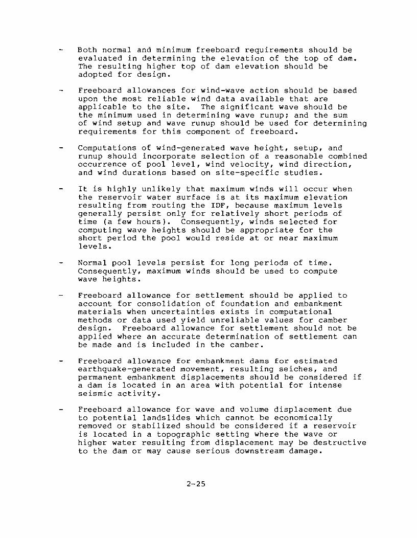
Both normal and minimum freeboard requirements should be evaluated in determining the elevation of the top of dam. The resulting higher top of dam elevation should be adopted for design.
Freeboard allowances for wind-wave action should be based upon the most reliable wind data available that are applicable to the site. The significant wave should be the minimum used in determining wave runupi and the sum of wind setup and wave runup should be used for determining requirements for this component of freeboard.
Computations of wind-generated wave height, setup, and runup should incorporate selection of a reasonable combined occurrence of pool level, wind velocity, wind direction, and wind durations based on site-specific studies.
It is highly unlikely that maximum winds will occur when the reservoir water surface is at its maximum elevation resulting from routing the IDF, because maximum levels generally persist only for relatively short periods of time (a few hours). Consequently, winds selected for computing wave heights should be appropriate for the short period the pool would reside at or near maximum levels.
Normal pool levels persist for long periods of time. Consequently, maximum winds should be used to compute wave heights.
Freeboard allowance for settlement should be applied to account for consolidation of foundation and embankment materials when uncertainties exists in computational methods or data used yield unreliable values for camber design. Freeboard allowance for settlement should not be applied where an accurate determination of settlement can be made and is included in the camber.
Freeboard allowance for embankment dams for estimated earthquake-generated movement, resulting seiches, and permanent embankment displacements should be considered if a dam is located in an area with potential for intense seismic activity.
Freeboard allowance for wave and volume displacement due to potential landslides which cannot be economically removed or stabilized should be considered if a reservoir is located in a topographic setting where the wave or higher water resulting from displacement may be destructive to the dam or may cause serious downstream damage.
2-25

Total freeboard allowances should include only those components of freeboard which can reasonably occur simultaneously for a particular water surface elevation. Components of freeboard and combinations of those components which have a reasonable probability of simultaneous occurrence are listed in the following paragraphs for estimating minimum, normal, and intermediate freeboards. The top of the dam should be established to accommodate the most critical combination of water surface and freeboard components from the following combinations.
For minimum freeboard combinations the following components, when they can reasonably occur simultaneously, should be added to determine the total minimum freeboard requirement:
(1) Wind-generated wave runup and setup for a wind appropriate for maximum reservoir stage for the IDF
(2) Effects of possible malfunction of spillway and/or outlet works during routing of the IDF
(3) Settlement of embankment and foundation not included in crest camber
(4) Landslide-generated water waves and/or displacement of reservoir volume (only cases where landslides are triggered by the occurrence of higher water elevations and intense precipitation associated with the occurrence of the IDF).
For normal freeboard combinations, the most critical of the following two combinations of components should be used for determining normal freeboard requirements:
(1) Combination 1
(a) Wind-generated wave runup and setup for maximum wind, and
(b) Settlement of embankment and foundation not included in camber.
(2) Combination 2
(a) Landslide-generated water waves and/or displacement of reservoir volume;
(b) Settlement of embankment and foundation not included in camber; and
2-26

(c) Settlement of embankment and foundation or seiches as a result of the occurrence of the maximum credible earthquake.
For intermediate freeboard combinations, in special cases, a combination of intermediate winds and water surface between normal and maximum levels should be evaluated to determine whether this condition is critical. This may apply where there are exclusive flood control storage allocations.
2-27

2-5. References
1. American Nuclear Society (1981). Determining Design Basis Flooding at Power Reactor Sites. ANSI/ANS-2.8-1981. Permission to use portions of this publication was granted by letter dated February 25, 1987.
2. Committee on Safety Criteria for Dams (1985). Safety of Dams - Flood and Earthquake Criteria. Prepared under the Auspices of Water Science and Technology Board, Commission on Engineering and Technical Systems, National Research Council, Washington, D.C.: National Academy Press, 374 pp.
3. Federal Emergency Management Agency (1984). Federal Guidelines for Selecting and Accommodating Inflow Design Floods for Dams. Prepared by Horking Group on Inflow Design Flood SUbcommittee 1 of Interagency Committee on Dam Safety.
4. Federal Energy Regulatory Commission 1986. Operating Manual for Inspection of Projects and Supervision of Licenses for Water Power Projects.
5. Hydrology Subcommittee, 1981. Estimating Peak Flow Frequencies for Natural Ungaged Watersheds: A Proposed Nationwide Test. U. S. ~vater Resources COuncil, 346 pp.
6. Hydrology Subcommittee, 1982. Guidelines for Determining Flood Flow Frequency. Hydrology Subcommittee Bulletin l7B, with editorial corrections. Interagency Advisory Committee on Water Data, U.S. Geological Survey, 28 pp.
7. Interagency Commi ttee on ~'Jater Data (1985 Draft). Feasibility of Assigning a Probability to the Probable Maximum Flood. Prepared by Working Group of Hydrology Committee.
8. International Symposium on Flood Frequency and Risk Analyses at Louisiana State University, Baton Rouge, La. May 14-17, 1986. Proceedings to be published late 1986.
9. Lane, ~v. L., 1985. Rare Flood Frequency Estimation -A Case Study of the Pecos River, (Abstract). EOS Transactions of AGU, 66(18), 267.
10. Myers, V.A., 1969. The Estimation of Extreme Precipitation as the Basis for Design Floods - Resume of Practice in the United States. Proceedings of the Leningrad Symposium on Floods and Their Computation, August 1967, Vol. 1, International Association of Scientific Hydrology, Gentbrugge, Belgium, 84-101.
2-28

11. Naef, F., 1981. Process Today?
Can \'Je model the Rainfall-Runoff Hydrological Sciences Bulletin, 26.
2-29

2-6. APPENDICES
2-30

APPENDIX IIA
DAMBREAK STUDIES

APPENDIX IIA
Dambreak Flood Studies
The evaluation of the downstream consequences in the event of a dam failure is a main element in determining hazard potential and formulating emergency action plans for hydroelectric projects. The solution requires knowledge of the lateral and longitudinal geometry of the stream, its frictional resistance, a dischargeelevation relationship at one boundary, and the time-varying flow or elevation at the opposite boundary.
The current state-of-the-art is to use transient flow or hydraulic methods to predict dambreak wave formation and downstream progression. The transient flow methods solve and therefore account for the essential momentum forces involved in the rapidly changing flow caused by a dambreak. Another technique, referred to as storage routing or the hydrologic method, solves onedimensional equations of steady flow ignoring the pressure and acceleration contributions to the total momentum force. For the same outflow hydrograph the storage routing procedure will always yield lower water surface elevations than hydraulic or transient flow routing.
When routing a dambreak flood through the downstream reaches appropriate local inflows should be included in the routing, consistent with the assumed storm centerings.
The mode and degree of dam failure involves considerable uncertainty and cannot be predicted with acceptable engineering accuracy; therefore, conservative failure postulations are necessary. Uncertainties can be circumvented in situations where it can be shown that the complete and sudden removal of a dam (or dams) will not endanger human life or cause significant property damage.
The following provides references on dambreak analyses and criteria which may prove useful as indicators of reasonableness of the breach parameter, peak discharge, depth of flow, and travel time determined by the licensee.
I. REFERENCES
Suggested acceptable references regarding dam failure studies include the following:
A. Westmore, Jonathan N. and Fread, Danny L., "The NWS Simplified Dam-Break Flood Forecasting Model," National Weather Service, Silver Spring, Maryland, 1981. (Copy previously furnished to each Regional Office with a detailed example)

-2-
B. Fread, D. L., 1977: The development and testing of a dambreak flood forecasting model, "Proceedings, Dam-Break Flood Model i ng Horkshop," U. S. vlater Resources Counc iI, Washington, D.C., 1977, pp. 164-197.
C. Fread, D. L. "DAMBRK - The N~lS Dam-Break Model," National Weather Service, Silver July 18, 1984 (Reprinted February 1987). preferred method for performing dambreak
Flood Forecasting Spring, Maryland,
(This is the studies).
D. Hydrologic Engineering Center, "Flood Hydrograph Package (HEC-l) Users Manual for Dam Safety Investigations," September, 1981 (Revised January 1985).
E. Gandlach, D. L. and Thomas, W. A., "Guidelines for Calculating and Routing a Dam-Break Flood," Research Note No.5, U.S. Army Corps of Engineers, Hydrologic Engineering Center, 1977.
F. Cecilio, C. B. and Strassburger, A. G., "Downstream Hydrograph from Dam Failure," Engineering Foundation Conference on Evaluation of Dam Safety, 1976.
G. Soil Conservation Service, "Simplified Dam-Breach Routing Procedure," March 1979. (To be used only for flood routing technique, not dambreak discharge.)
H. Chow, V. T., Open Channel Hydraulics, McGraw-Hill Book Company, Inc., New York, 1959, Chapter 20.
I. Henderson, F. M., Open Channel Flow, McMillan Company, New York, 1966, Chapters 8 and 9.
J. Hydrologic Engineering Center, "Flood Emergency Plans, Guidelines for Corps Dam," June 1980. (Forwarded to all Regional Engineers by memorandum dated February 11, 1981).
II. CRITERIA
The following criteria may prove useful as an indicator of the reasonableness of a dambreak study:
A. If the dambreak analysis has been performed by an acceptable method (Reference C is the preferred method), then generally only the breach parameter, peak discharge, and flood wave travel time should be verified as an indicator of the licensee's correct application of the method selected. Downstream routing parameters (i.e., Manning's "n") should be reviewed for acceptability and inundation maps should be reviewed for clarity and completeness of information (i.e., travel times). The following criteria are considered to be adequate and appropriate for verifying the selected breach parameters and peak discharge:

-3-
1. Breach Parameter - Most serious dam failures result in a situation resembling weir conditions. Breach width selection is judgmental and should be made based on the channel or valley width with failure occurring at the deepest section. The bottom of the breach should generally be assumed to be at the foundation elevation of the dam. Pages 8, 8A, 8B, and 9 of this appendix contain suggested breach parameters and should be used when verifying the selected breach parameter. For worst case scenarios, the breach width should be in the upper range while the time of failure should be in the lower range. However a sensitivity analysis is recommended to determine the reasonableness of the assumptions.
2. Peak Discharge - The peak discharge may be verified by use of equations (11) and (13) of Reference No.1. Although the equations assume a rectangular-shaped breach, a trapezoidal breach may be analyzed by specifying a rectangular breach width that is equal to the average width of the trapezoidal breach.
Equation 11:
c = 23.4 As
Br
Where C = constant
As = reservoir surface area, in acres
Br = average breach width, in feet
Equation 13:
Qbmax = 3.1 Br f. \tf +
Where Qbmax = maximum breach outflow, in cfs tf = time of failure, in hours
H = maximum head over the weir, in feet
This equation for Qbmax has been found to give results within +5% of the Qpeak from the full D~MBRK model.
In a rare case where a dam impounding a small storage volume has a large time of failure, the equations above will predict a much higher flow than actually occurs.
At a National t'leather Service Dam-Break Hodel Symposium held in Tulsa, Oklahoma, June 27-30, 1983, Dr. Danny Fread presented an update to his simplified method. Equation 13 has been modified

-4-
as follows to include additional outflow not attributed to breach outflow:
Qbmax = 00 + 3.1 Br
Where Qo = Additional (non-breach) outflow (cfs) at time tf (i.e., spillway flow and/or crest overflow) (optional data value, may be set to 0).
This equation has also been modified to address instantaneous failure, because in some situations where a dam fails very rapidly, the negative wave that forms in the reservoir may significantly affect the outflow from the dam.
3. Flood Wave Travel Time
Reasonableness of the flood wave travel time may be determined by use of the following "rule-of-thumb" approximation for average wave speed:
(a) Assume an equivalent rectangular channel section for the selected irregular channel section
(b) Assume a constant average channel slope
(c) Compute depth of flow from the following adjusted Manning's equation.
d = (-Qn
)
0.6
0.5 1.49 B(8)
Where: d = depth of flow for assumed rectangular section, ft.
Q = peak discharge, cfs
B = average width (rectangular), ft.
8 = average slope, ft/ft
n = Manning's roughness coefficient
(d) Compute average velocity from Manning's equation:
v = 1.49 (8) 0.5 (d) 0.67 n

-5-
Where: V = average velocity, fps
(e) Compute wave speed, C (kinematic velocity):
C = 5 V (0.68) 3
Where: C = wave speed (mph)
(f) Determination travel time, TT
TT = x C
Where: TT = travel time, hr. x = distance from dam, mi.
Note: If the slope is flat, the following "rule-of-thumb" provides a very rough estimate of the wave speed:
0.5 C = 2(S)
Where: C = wave speed, mph S = average slope, ft./mi.
In addition, as a "rule-of-thumb", the dynamic routing (NWS) method should be used whenever severe backwater conditions at downstream areas occur and/or the slope is less than 20 ft/mi. Otherwise, normal hydrologic routing (HEC-l) is usually acceptable. It is recommended that HEC-2 be used to determine the resulting water surface elevations when HEC-l is used for the dambreak study.
B. If a dambreak analysis has been performed by a method other than one of the suggested acceptable methods, the selected breach parameters, peak discharge, depth of flow and travel time of the flood wave shall be verified by one of the two methods:
1. Unsteady Flow Method (Recommended)
"The NWS Simplified Dam-Break Flood Forecasting Model" (Reference A) and "DAMBRK" (Reference C) are the recommended methods. As the flood wave travels downstream, the peak discharge generally, but not always, decreases along with the wave velocity. This attenuation in the flood wave is primarily due to energy dissipation when it is near the dam and to valley storage as it progresses in an unsteady flow downstream. For all parameters calculated, this method should usually give results within +10% of the parameters determined from using the full DAMBRK model.

-6-
2. Steady Flow Method (Provides a rough estimate) If this method is selected, the breach parameter and peak discharge shall be verified as in part "A" above.
For a rough estimate of the travel time and flood wave, it is recommended that one of the following two steady state methods be used for verification of the licensee's values:
a. When stream gage data is available, the depth of flow and travel time can be estimated as follows (This method will indirectly take valley storage into consideration.) :
(1) Identify existing stream gages located downstream of the dam.
(2) Obtain the stage-discharge curve for each gage.
(3) Assuming Q peak remains constant, extrapolate the curves to the Q peak value of the flood wave and determine the corresponding water surface elevation.
(4) Using the continuity equation to determine the velocity, estimate the travel time between each cross-section.
b. When stream gage data is not available, the depth of flow and travel time can be estimated based on the following steady-state method:
(1) Assume the area downstream of the dam is a channel. This will neglect valley storage.
(2) Identify on topographic maps all abrupt changes in channel width and/or slope. Using this as a basis, select and plot channel cross-sections.
(3) Assume Q max remains constant throughout the entire stream length under consideration.
(4) Selecting a fairly rough Manning's n value, determine the depth of flow by applying Manning's equation to each cross-section. Assume the energy slope is equal to the slope of the channel.
(5) Using the continuity equation to determine the velocity, estimate the travel time between each cross-section.

-7-
C. The above criteria for breach parameter, peak discharge, depth of flow, and travel time should provide the necessary "ballpark figures" needed for comparison with licensee's estimates. When large discrepancies in compared values exist, or questions arise about assumptions to be made, or it appears that an extensive review will be necessary, the Regional Director should contact the Washington Office, DINS for guidance. It should be emphasized that the intent is to review and not to make an independent analysis and that normally the studies submitted by the dam owner need not be verified if the methodology used appears to be satisfactory. The methodology is construed to be a part of the study and should be requested if not included.

- 8 -
~.~RU: '. ~GGESTED BREACH Pl·FAt1L::'PS
(Defimtion Sketch Srown in figure 1)
parameter
Average width of Breach (BR) (see Carment ~. 1)
Horizontal Component of S ide Slope of Breach (Z) (See Comment ~O. 2)
Time to Fail ure (TFH ) (in hours)
(See Ccnment No.3)
Value
AD < BR < SAD (usually-between
2HD & 4HD)
BR > 0.8 x Crest Length
BR = Crest Length
8R = Width of 1 or More 1<'ono 1 i ths , usually BR ~ 0.5 W
o < Z < 2
Z = 0
1/4 < Z < 1
1 < Z < 2
o < Z < slope of valley-wall s
0.1 < TFH < 1
Type of Darn
Earthen, Rockf ill
Slag, Refuse
Concrete, Arch, Timber Crib
Masonry, Gr'avity
All
Masonry, Concrete Timber C:rib
Earthen (En:;1'ineered, Canpacted)
Sla;!, Pefuse (Non-F:rgineered )
Arch
All
TFH < 0.1 Arch, Timber crih
0.1 < TFH < 0.3 Masonry, Concrete
0.1 < TFH < 1.0 Earthen ( ErYJ ineered, Canpacted)
n.l < TFH < 0.5 Earthen (Non Engineered, Poor Construction)
0.1 < TFH < 0.3 Slag, Pefuse
Definition: HI) - Beiqht of ['am Z - Horizontal Component of Side Slope of Breach
8R - Average Width of Breach 'IFH - Time to FUll y Form the Breach
W - Crest Lenqth Carments : See page 3A-88

-SA-
Comments:
1. BR is the average breach width, which is not necessarily the bottom width. BR is the bottom width for a rectangle, but BR is not the bottom width for a trapezoid.
2. Whether the shape is rectangular, trapezoidal, or triangular is not generally critical if the average breach width for each shape is the same. What is critical is the assumed average width of the breach.
3. Time to failure is a function of height of dam and location of breach. Therefore, the longer the time to failure, the wider the breach should be. Also, the greater the height of the dam and the storage volume, the greater the time to failure and average breach width will probably be.
4. The bottom of the breach should be at the foundation elevation.
5. Breach width assumptions should be based on the height of the dam, the volume of the reservoir, and the type of failure (e.g. piping, sustained overtopping, etc.).
6. For a worst-case scenario, the average breach width should be in the upper portion of the recommended range, the time to failure should be in the lower portion of the recommended range, and the manning's "n" value should be in the upper portion of the recommended range. In order to fully investigate the effects of the impacts of a failure on downstream areas, a sensitivity analysis is required to estimate the confidence limits and relative differences resulting from varying failure assumptions:
a. To compare relative differences in peak elevation based on variations in breach widths, the sensitivity analysis should be based on the following assumptions:
1. Assume a probable (reasonable) maximum breach width, a probable minimum time to failure, and a probable maximum manning's "n" value. Mannings's "n" values in the vicinity of the dam (up to several thousand feet or more downstream) should be assumed to be larger than the maximum value suggested by field investigations in order to account for uncertainties of high energy losses, velocities, turbulence, etc., resulting from the initial failure.

-SB-
Comments:
2. Assume a probable minimum breach width, a probable maximum time to failure, and a probable minimum manning's Un" value.
Plot the results of both runs on the same graph showing changes in elevation with respect to distance downstream from the dam.
b. To compare differences in travel time of the flood wave, the sensitivity analysis should be based on the following assumptions:
1. Use criteria in a. 1.
2. Assume a probable maximum breach width, a probabJ.e minimum time to failure, and a probable minimum manning's Un" value.
Plot the results of both runs on the same graph showing the changes in travel time with respect to distance downstream from the dam.
c. To compare differences in elevation between natural flood conditions and natural flood conditions plus dambreak, the sensitivity analysis should be based on the following assumptions:
1. Route natural flood without dambreak assuming maximum probable manning's Un" value.
2. Use criteria in a. 1.
Plot the results of both runs on the same graph showing changes in elevation with respect to distance downstream from the dam.
7. When dams are assumed to fail from overtopping, wider breach widths than those suggested in Table 1 should be considered if overtopping is sustained for a long period of time.

HD
" " "
~ ______ water surface of reservoir
/ /
/
~ __ -rater surface of tailrace
FIGURE 1. DEFINITION SKETCtl OF 8REACII PARNIETERS
-9-

APPENDIX lIB
REVISED EMERGENCY ACTION PLAN GUIDELINES

UNITED STATES or AMERICA FEDERAL ENERGY REGULATORY COHHISSION
NOTICE Of REV' SED EMERGENCY ACTION PLAN GUIDELINES
(April 5, 1985)
Pursuant to the authority in Section l2.22(a)(1) of the Commission's Regulations, the Director, Office of Hydropower Licensing, h.1I rev'hed the guidelines for the preparation of emergency action plana (EAP). The guidelinel have been revised to facilitate the preparation, annual revJew and updating of EAP's to ensure their effectlvenesl and workability. The guidelines should be uled in conjunction vlth the instructions contained in Part 12, Subpart C of the Commillion's Regulations.
OWners/developers (herein referred to as owners) of all dams under Commission jurisdiction MUlt develop and file an EAP with the Regional EIIgineer unless .n exe .. ptlon is obtained pursuant to Section 12.21 of the Regulations. All reQuired EAP's developed subseauent to the date of this notice must follow the format established in the revised guidelines. Owners are not required to rewrite a~d'refile existing EAP's in accordance with the established format. However, as part of the annual review and updatinQ process, owners should determine whether their EAP's can be enhanced based on the Information in the revised guid~lines and are, therefore, urged to consider reor9anizing their tAP's in the format described therein.
Copies of the revised guidelines are available from the Director, Division of Inspections or the Regional Engineer.
Kenneth F. Pl~ Secretary
[)c-A-)~
GUIOELINER FOil PREPARATION OF EKERC:ENCY ACTIO"! PLAtl!;
1. purpose. These. Quidel ines are for the purpose of deUnlI)g the reQuir .... ents of an acceptable emergency action plan (EAP) and for facilitating its preparation and annual testinQ and update. An emergencv is defined as an impending or actual sudden release of water caused by an accident to, or failure of, project structures.
2. Background. The "Guidelines for Preparation of Fmergency Action Plans" were established in ~ove~her 1979. The Quidellnes were subsequently included al the Appendix to Order 1'10. 122 of the Commission's Regulations, issuer! January 21, 1981. Section 12.22(al(11 of that Order states that "an emerQency action plan must conform with the Quidelines established, and from time to time rev i sed, ••••• The demand for more spec i f ic, comprehensive guidelines resulted in this revision to the Quide-lines: .
3. Scope. The quidelines establilih a. specific for~at (see Tteiii""41 to assist in preparing an effect ive, workable UP. The format was dl.!veloped to include all the pertinent information required for the tAP itself and its accOll'panying appendix. In providing the appropriate Inforl'lation, the UP should be site specific, reflecting mode of oper at ion, internal and ex ternal means of coml'lun Icat ion, and interaction with appropriate agencies and owners of other sites. The forlllat should be used in con1unctlon with the instructions contained in Part 12, Subpart C of the Commission'S ReQulations.
It is not imperative that current EAP's be revised to comply with this for~at. However, each EAP should conta ina discuss ion of the me thod for Impl ement I ng the notification plan in a timely manner. It is recommended that the owners use thelle guidelines to facilitate the annual rev iew and updatin9 of the workability of an EAP. The Re9ional Engineer is to be advl!!e.:! of the results of thi s annual rev iew pr ior to December 11 of each year.
H
~

- 2 -
tinder thp provisions of Sec:tion 12.221cl of the COIIIlda,;ion's PeQulat ions, "ach own"r of a hydroelect.riC: pro1ect under the 1urlsdictiCln of the COIII .. taaion witt. operatinq or other per60nnpl located within a lO-.. lle radiul! of a nuclear power ~lant r"actor ~uat prepare a radioloqical ~erqency reaponae plan to h" implement"d in the event of a sever" accident or incidpnt resultina in the release of radioactive .aterhls from a nucl par pI ant. The (lU idl'l ines for preparat'ion of a radioloaical "merraency reaponae plan laee ite .. SI should be used in coniunction with the ,instructiona contained in Spction 12.22(cl of the Commisaion's Pegulationa.
4. The FCl(mat. The followino paqealparae) thru 221 cOlllpriae the fOrJllat by wh ich all newl y reaui red' r,AP' a are to be defteloped. Thia for.-at should facilitate the preparation, updat ino, and annual rev iew of an E'P. It shoulc;l be ulled in con1 unction with t.he inatructions contained in Part 12, SubDclrt C of the Commission's Peaulations. The forlll,t waa developed to includ" all of the pertinent infor.-ation to be included in the EAP as reaulred by t.he COIIIIIIlsalon'a Pegulations. It la recomlllended that the EAP be bound usina a lIIethod, such as a three-ring binder, whereby Dutdated pages can be "asilv removed and replaced by updated infonlllltion to ensure a ~omplete, current, and workable plan.
- ) -ITitle "a9p l
Dtt;RGt;NC Y ACTION PLAN
tNUle) of [)eveloJllllent
Proiect No. IFt;PC No.1
Na.e of the licenaee/exa.ptee/applicantl
Addresa I
Subaitted Idatel

- 4 -
Verificationl
State of ) , county of
The undersioned, beinQ first duly sworn, statea that Ihe,
she) has read the followi~ docu~ent and knowa the contents
of it, and thilt all of the atatements contained in thilt
document ar~ true and correct, to the beat of I his, her)
knowledqe and belief.
(N .. e of person slonlnol
( Tltlel
Sworn to and lIubscribed before.e this Idayl of IMonth), Iyearl.
SEAL
(slonature of Notary Public or other state or local official authorized by law to notarize doeu.ents) •
- 5 -
Contenta 01 the Plan
J. t!otific .. tion flowchart
A. Failure ia '~~inent or haa occurred
R. potentially hazardoua aituation is developinq
H. General Reaponsibilitiea Under the Dlergency Action Plan
III. Notification Procedures
A. failure ia imminent or has occurred
B. Potentially haurdoua situation is deyelopill9
IV. "itiQation Activitiea
A. Ceneral provisions for surveillance
B. surveillance at r_otely controlled or \lnat tended da~s
C. Response during periods of darkness
D. Availability and use of alternate systeMS of communication
E. ~erQancy supplies and resources
,. Other concerns and actions
V. Append ix
A. Description of the project
R. Su~ary of study and analyses to deterMine e.tent of inundation
C. I nunda t ion 14apa
D. plana for training, te.tinQ, and annual review
E. Docuaentation
Paoe No.

I •
II.
- ,. -EHERGF.NC'V ACTION PLAN
Notification Flowchart
• Provide a flowchart sU"'lIIarizino clt'arly who iR to be notified and who is respanslblt' for notifying which owner re(,resentative(,) and/or (lUblic officialC,), and in what priority for the following e~ergency situationsl
A. failure i. Imminent or has occurred.
~. Potentially hazardous situation is developing. Situation wher. a failure .ay develop. but preplanned actions takltn durinq cettain ~vents (such as lIIajor floods. earthquake,. evidence ot piping, etc.) .ay prevent or .ltigate hilure. Foven if failure is inevitable. IIIOre ti~e 1s generally availahle than in situation A above to issue warnings and/or take preventative actions.
• Include individual names and position title&, otfice an~ home telephone n~hers. and alternate contacts and m.ans of catllllunicat'ion.
•
•
The flowchart should be easy to follow under ellleroency conditions and should non&ally b. limited to one page for each failure .ode. Color codinQ lIIay prove helpful. (Detailed infOl'lllation supplementing the flowchart should be provided in Section III of the emergency act ion pi an) •
Additional copies of the flo..,chart should be readily ava il abl e to each i nd i vidual hav i ng res pons ib il it iea thereon. and ahould be kept up-to-date through tests and revisions.
Note: ,. ..... ple flowchart is included on page 7 ot these ~uidelines.
General Respon&ibilities under the Emergency Action Plan
• Advise the operators of importance of the emergency action plan (EAP) and why the EAP is necessary. Describe operators duties in implementing the EAP. Give pointers on how to conununicate the _erQency situation to those who need to be contacted. Include samples ot typical cO~lIIunications.
- 7 -
t ! j t

- 8 -
Oescl"ihe the chain of COlllmand. L.censee~exemptee! appl icant (henin l"efened to all licensee) officl~ls a:ld alternates wh.ch IIIUst be notified should be deSlQnated and pdol"itY of notification detemined. Notification of supel"vlsol"Y pel"sonnel on the licensee staff is desil"able, if time penaita. Advice .,.ay be needed concel"ning pl"edetenlllned l"ellledial action to delay, Ol" mit iQate the severity of, the failul"e. For ex~ple, a pel"son may be dispatched to an unmanned ,dam during a major flood to observed And monitor the sltuation'cUl"ectly. The EAP should be coordinated with hioh enouqh levels of Manaqelllent ~o insure full awareness of organlzatl'lnal capabilities and responsibilities. It IIIUSt always be developed as a result?f coordination and consultation with other entitles and aoencies that will be affected by a failure. or have statutory responsibilities In warning and evacuation.
The pel"sonls) authodzed to notify local officials should be determined and clearly set forth in ,each EAP. Under certain situations, such as where failure iii imminent or has occurred, this authority Wlay have to be del eoa ted to t he dam operator or local of f ic I al and the responsibility should be clearly outlined in the EJ>.P. The Nat lanaI weather Service (NWS) ha~ the Qeneral resl'onsihll Ity to i'5sue flood warnlngs. Therefore. it lIIay be beneficial to notify the "'WS ,of any pendino or actual dam break flooding so that its facilites could enhance warninps beiOQ issued.
Designate means for keeping local authorities advised of conditions at the dam. The comllliesion does not intend for licensees to usurp the responsibility of ooveromental elements for evacuation of people. However, there may he situations wher, routine notification will not suffice, euct- as a resident located just below the dam. In this CIIse, the licensee should arranoe to notify that person directly. This should be coordinated with the pertinent public offichls.
Include any other infomation considered pertinent.
- 9 -
In. Notification Proce"uree
• Include in the notification portion of the EAP all per sons to tie not I f ied as soon as an emerl;jencY situation develops. lncluc)e in1ividual names and position titles, . location, office and nome telephone nUI'lt;.ers, and radio communication fl"eauencies and call sipnals, if available, fOl" owner personnel, public officials, and othel" pel"sonnel, including alternates. For each emel"Qency situdtlon, clearly indicate who is to ",ake a call and to whom it is to be lIIade, and in what pdodty.
• The nUlllb"r of ",el"sons to be not if led by each resJlQnsible Individual in the notification plan should be governed by what other responsibilities the person has been assiQned.
[lesc ribe in deta iI the not if icat ion procedures for the two emeraency situations.
A. Failure is imminent or has occurl"ed
B. Potentially hazardous situation is developino
Describe actions to be taken and contacts to be made. Pl"iorityof notification should address the actual emer~ency situation:
1. Detailed plan for notification
Residents and owners of pl"operty that are located immediately downstrea~ of the dam within the boundary Qf potent ial inundation where available warning tillle is very limited. Give nallles and telephone numbers (day!nioht), and al terna te means of c a-.III un icat Ion. If not applicable, so state.
Licensee personnel. Give names and telephone nunobers (day!ni9ht) of resPOnsihle Individuals and al ternate means of canmunication.
taw enforcement officials. Give nar-es and telephone numhers (dav!night) and alternate means of communication.

2.
- 10 -
0perators of other dams or water-retentions facilities: Give names and telephone nu",t-r.rs (day/night) and al ternate means of cOPUllun icat ion. I f not appl icable, so state.
Managers and operators of recreation faciiities. Give nallles and telephone numbers (day/niQht) and alternate lIIeans of cOllUllun icat ion. I f not appl ieable, so sta te.
Appropriate cies. Give (day/night) calion. If
Federal, ~tate and local agennames and telephone numbers
and alternate means of cGmllluninot applicahle, so state.
Others, as approrriate. Give nAilles and telephone nUlllbers (day/night) and alternate means of communication.
Poet Ing of the Notification Flowchart and distribution of EAP
(\escl'"it-e where the notification flowctoart for each emergency situation will be posted. It should he in a prominent location readily access it-Ie at the project site near a telephone and/or radio transmitter. A copy of the cOIIIplete emergency action plan should also he available to the operators and dispatch center personnel.
Oistribute the FAP to operational and supervisory employees and othen who will be required to take certain actions when the plan is put into effect.
IV. Miti9ation Activities
A. General provisions for surveillance
The ~AP should contain a discussion of provisions for surveill.mce and detection of an emergency situation and should clearly indicate that it can be implement .. d in a timely manner. An important consideration in the effectiveness of the EAP is the prompt detection and evaluation of information ohtained from instrwnentation and/or physical inspection procedures.
1'.
- 11 -
niscus~ t i.qoj f~ctor from aClual "",el'"qency OCCUri:nCI, to awareness of emergency and its effect on the workabilitvof the EAP. Timely i",pl_entation of the F.AP is a crucial elelllent in its effectiven'Oss.
Describe any other specific actions to t:e taken.
Surveillance at remotely controlled or unattended dams (not manned on a 24-hour per day basis).
Describe any instrulllentation alaras, video cameras, etc.) of unat.tended dams and how be impl_en ted •
(such as audible/visual for ",onitoring behavior warning syste'fts would
[lescribe procedures for prov Iding round the clock surveillance for periods of actual or forecasted high flows.
If not applicable, sQ state.
c. Response during periods of darkness
Describe actions to be taken to illuminate the spill way operat i no deck or other act ions necessary to lac·il iate opening or closing of gates or other necessary actions. Describe e~ergency operation of spillway gates during power failure. Refer to E-) of this section.
Describe special procedures for contacting the proper pe~sonnel and officials.
I ncl ude any other spec i al lnst ruct ions to the operators.
D. Availability and use of alternate systems of communication
• [lescribe alternative channels of communication to be used in case of failure of the primary systel'l or failure of other systems i,ftllledlately available.

- 12 -
Descrihe proper procedures to activate the alternat ive channels of comlllunication. Pelllelllber that you direcL these instructions tp your e~ploye~s.
Include any other special instructions.
-E. Emerqency supplics ancl resources
I. Stockpil iOQ of materials for emergency USIl or repair.
Describe materials, their location and intended use.
Descrihe eouip ... ent to be used, its location anti who will operate it.
(lescr ibe how the operator is contacterl.
Include any other special instructions.
If not applicable, 60 state.
2. roordin~tion of flows
lIeserihe the need tor advanced coordination of flows based on weather and runoff forecasts. Incluc1e special instructions. Describe how the coordination is aChieved and the chain of communication, including names and day/night telEphone numbers of responsible personnel. lhe I icensee is encouraqed to coordinate with the National Weather Service CNWS) tQ monitor storms as well as the flood wave resulting from a dam break. The NWS Dlay also be able to supplement the warnings being issued by using its own c~unication systeA.
Oescribe additional actions contemplated to respond to an emergency situation or failure at an unattended dan •• Include periods of darkness, incl e",ent weather, and non-business hours.
- 13 -
Ilesc r ibe actionfl to he taken to lower the reservoir water surface elevation. If n~t appl icable, so state. Instruct operators on when and how this acti~n should be taken.
Describe actions to be taken to reduce inflow to the reservoir (rom the upstreAIII dams or control structures. rf not applicable, so state. Instruct operators or Gther persons responsihle for contact with other owners on when and how this action should be ta~en.
Describe actionll to be taken to reduce downstream flows, such a~ Increasing or decreasing oULflows from downstream d~s or control structures on the waterway on which the project is located or its tributaties. If not appl icable, so state. Instruct operator~ on when and Itow this action should be taken.
Describe any other actions to be taken.
3. Al ternat ive s(~urces of power for spillway Qate operat ion anli other emerqency uses.
DesC'r ibe the al ternat ive SOUlces of power, their location, and DIode of operation, a.,.:! if portahle, the means of transportation and routes to be followed. Include the name and day/night telephone nUlAber of the operator. If not applicable, so state.
4. Other actions devised to mitiflate the extent of possible emergencies.
(lescribe other site specific actions or conditiona which in your judgment will contribute to mitigation of elllergencies.

- 14 -
f. Oth~r conc~rn& and action.
('Iescrib. any other conc.rn •• nd .ctlon. to b. Ulten.
V. App~nd i "
A. I'el!'criDt ion of the I\roj.ct
1. Prov id •• de .cr i pt ion of the project.
2. Provide a de.cription of the up.tre ..... nd downstr •• m .r •••• nd tOPQ9r.phy.
R. Su~.ry of .tudy .nd .n.lv ••• to d.t.rlDin, •• tent of inundation
1. Id.ntify .nd bri.fly d •• crib. the .uthod .el.ct.d to id.ntify the inund.t.d .r ••••
2. St.te ill .ssumption. I including, but not lilDit.d to, reservoir inflow condition (norm.l or flood), tempor.l Itim.) .nd geom.tric.l d •• cription of br •• ch, "annin~'. -n- etc.) Sev.r.l diff.rent .ssumption. could b ••• d. rep.rdino the .ppropri.te condition pr.v.iling .t the ti ... of • d •• f.ilure.
However, it !Day be i .. pract ical to .n.l YI. ..ch potenti.l .m.rg.ncy which could b. po.tul.t.d. A f.ir we.th.r d ... br •• k (r ••• rvoir .t nonn.l m"xi .. um full pool .1.vAtion, non .. l .tr.4IIIflow prev.ilino) h oener"lly con.id.red to h.v. the mO!lt pot.nt i.l for lo.s of 1i f.. Th.r. for., the min hllUIII cond it ion to b. consid.r.d h the to ir w •• th.r d~ br •• k. How.v.r, f.ilur. during v.ri-01,1. flood fl ow cond i t ion. .hould b. consid.r.d • nd .hould b. u •• d if th.y would id.ntify .p.ci.l probl.m. of 'loodin~ r.ouirin~ ch.no.. .nd/or .dditions to the notifi~.tion proc.dur... Th. Commi •• ion, or it. .uthoril.d r.pr ••• nt.tive, r.t.in. the right to r.ouir., on • c ••• -by-c ••• b.sis, .n inve.tioation of oth.r flood flow !lcen.rio. to .n.ur. th.t .11 ca.munit •• r.ouiring notific.tion by local offici.l. h.v. b •• n identified.
- IS -
1. Th. domino .ff.ct - •• eauenti.l f.ilur. of ... 1,11-t.lpl. nUIllt>.r of down.tream d ..... s • r.sult of f.ilur. of the d.m for which the ... ero.ncy .ctiQn pl.n i. b.i09 pr.p.r.~ - .u.t be consid.r.d on • c ••• - by-c ••• t>.si.. If t h ••• su .. ed fa il ure 0 f the 1 icen ••• '. d .. would promote the f.ilur. of .nv d .... down.tr .... , the lic.ns.e h •• the r •• pon.it>ility to con.ider the domino eff.ct in the routing of the floodw.ve down.tr..... The floodw.v •• hould b. rout.d to the point where it no lon9.r pr ••• ntl • h.z.rd to down.tr ••• life or property (includina down.tre .. d .... ). Th.r.fore, the lic.n ••• , .fter •• sUlllinQ • hypoth.tical f.ilur. of it. da"', "Ult •••••• the .tructur.l inteprity of the down.tream dllJll (b ••• d on ."9in •• rin9 judQ .. ent or .ctu.l .n.ly.i.) to deterlllin. wh.ther it would b. prud.nt to con.id.r .ny of down.tr •• ", d ..... to f.il wtl.n .ubj.ct.d to the routed flood w.v.. If .pplic.hl., the d.tail. of dOlllino eff.ct •• hould be d •• cribed. I( not .pplic.ble, .o.t.t ••
4. Provide ju.tific.tion for e.ch ••• Wllptlon. The ••• umption. ",.d. r.garding the temporal and g.OIIIetr ical de.cript ion of • bre.ch i. d.pendent on the type of d .. b.inq .nalYled. flugQ •• t.d br •• ch par ... t.r •• r. includ.d on p.o. 21 .nd 22 of thes. ~uideline ••
S. Provid •• n elev.tion vi.w of the d.m .nd indic.t. the a •• um.d bre.ch.
6. De.crib •• pecial consid.r.tion. (.uch •• re.ervoir .lope .t.bility).
7. Provid.oth.r helpful inforlll.tion, ••• ppropri.te •
8. If. d.m-br.ak .nal y.h 101 ••• IIAd., prov id. re.ultl of the .tudy. Include pe.k di.ch.ro ••• nd .l.v.tiona and k.y loc.tion., floodw.v. tr.vel time to critical loc.tion., v.locity of flood w.ve. It. comput.r prooram w.. used, it lII.y b. .pprop~ i. t. to includ ••• ulIIIII.ry of the comput.r print-out.
c.
- 16 -
9. Discuss where flood routinc;J was tendnated. It should usually be terminated where non-dlllllaging flood l.vels are obtain.d. Howev.r, th.y lIay b. t.rminated at a point where r.al-tiM. flood warninc;J in formation can be prov id.d on a pr.pl ann.d basis. (For .xampl., if it is known that the ti •• of failure was 12.05, p .... and the fluodwav. can b. monitor.d, it may b. possible to d.t.rmin. that the floodwav. will r.ach Town X at approxhaat.ly 4:20 p.m., henc., real-tim. flood warning informatlon). If the flood routing is t.rminated b.fore non-damac;JiIl!J lev.ls are obtained, de.cribe in detail the plan for establi.hing and implem.ntinp real-tim. flood warning information.
Inunda t lor. Haps
Inundation maps are required for a) 1 high and significant hazard d.velopm.nts unless an unusual condition exists. Th. reQuirem.nts for an inundation map are as follows.
1. Identify the ant.cedent flow conditions on which the maps are based.
2. Ilescribe how the Inundation boundari.s wer. plotted. As a minimum, show on the map and/or in a table the max imUIII inundat Ion el.vat ion and the trav'" time of the front of the dam break flood wave to critical locations.
3. The map should b. d.veloped at a .cal. suf Cicient to b. used for identifying downstream inhabited areas within the area .ubject to poss ibl. danq.r. Inunda ted areas should h. clearly identified. It may be appropriate t~ liupplement the inundation maps with water surface profil.s at critical areas showinq the water surface elevation prior to failure and the peak water surface el.vation aft.r failure.
4.
5.
- J7 -
Th. b •• t available topoqraphic map should b. used. The exp.cted inundation following the a •• uMed failure .hould be del ineated on the map. The lines delineating the inundated area .hould be drawn in such thickne.. or fona (.olid line, dashed 1 ine, dot ted line) as to id.ntify the inundation limits as the main f.atureft of the Map but not bold .nough to obliterate hou.es or other features which are to he shown as being inundated bV the flood water •• Clarity is important. Wh.n plotting inundation liMits between cro.s s.ctions used for the analy.i., the 1 in.s should reasonably reflect the chang. in water levelS with conaiC:.ration piven to topoqraphic patterns and both natural and mamad. featur.s. Wh.n inundation 1 ine. enter the ar.a of an .x ist ing 1 aka or r.s.rvoir, they should be so drawn as to repr.s.nt an incr •••• in the water lev.l of such lake or r.s.rvoir. Should this increased wat.r level over top the d_, the appropr ia t. inundation lines should be drawn downstre_ of such dlllll to repre.ent expected inundation in the downstreaM chann.l up to a point wh.re an increase in wat.r lev.l will no lona.r repr.s.nt danger to life, health or prop.rty. The ar.a b.tw.en the inundation 1 ines r.presellt inq the water level .ay be shad.d to distinguished the area of inundation. Care should be tak.n to s.l.ct a shading which will not ol>literat. the background information .hown on the map.
Describe the accuracy and 11ulitation of the information supplied on the inundation maps and how b.st to use the maps. Since local officials are likely to us. the maps for evacuation purpos.s, a note should be included on the map to advise that, because of the method, proc.dur.s, and assUlllptions used to d.velop the flooded ar.as, thG I inllts of flooding shown and flood wave travel times are approx ima t. and should t.. us.d only as a quidelin. for establishino evacuation zones. Actual ar.as inundat.d will depend on actual failure conJitions and may differ from areas shown on the maps.

6.
- 18 -
If inundation maps are to b. shown on s.v.ral pag.s, a ~ap ind •• should b. includ.d to ori.nt the individual pao.s.
7. Includs any oth.r p.rtinent infonaation.
O. Plans for trainlnp, t.sting and annual revi.w
1. Annual traininq of proj.ct op.rators and oth.r responsible p.rsonn.l.
Oescr ibe pl ans to 'llv. detail.d instructions to the operators, attendants and oth.r responsible personn.l on how to respond properly to a project emergency. Include plans for discussing procedur.s to h. follow.d throughout the emerg.ncy and d.scribe the chain of com .. and dur I n9 day/nig ht or non-busine •• hours.
Describe plans to hold r.fr.sh.r seminars with operators.
2. Annual review and test of the stats of readin.ss.
•
Descr lh. plans to lIIak!, prompt updat.s of F.AP from comprehensive r.view. Must annually 6uppl y FERC wi th stat_ent that EAP has b •• n test.d, with inclusion of any n •• ded r.visions and updat.s or stat.Ment that no revisions and updates are nded.d. Provide all plan hold.rs copi.s of all r.vieions. Hark pag.s -R.vised HO/DA/YR/- and hiqhlight revis.d ~at.rlal.
Describe the annUAl test. Stat. who will be contact.d, wh.n and bow. Th. annual t.st should I nvolv. a eimula ted dr il 1 for on. of the .merqency situations. T.stlnq of r.~ot. aensina .Quipment at unmann.d dillas should b. included. Coordination and consultation with local gov.rnm.nt, law enforc_.nt officials and other orqaniaations should b. .ad. in order to .nhanc. the reali .. of th. test.
Oescribe action to b. tak.n •
•
- 19 -
Stat. who d.t.r~in.s if the t.st was succ.ssful.
Stat. plans for sub .. itting a critiQu. of the t.st to R.gional Engin •• r.
Oescrib. the ch.ckpoints.
E. Oocu..ntation
1. Provide docum.ntation of consultations with r.d.ral, Stat. and local ag.ncies, includin'l pub 1 ic sa f. t Y and law .n forcemen t bod i. s • Provide l.tt.rs of acknowl.dg ... ent from the contact.d ag.nc i.s.
• L.tt.rs Should indicat. that .ach agency involved und.rstands its re.pon.~bility for al.rting and/or .vacuating the public in those are~s within its jurisdiction.
2. Provide lett.rs or Memoranda of contact
• Coordination is 8ssential to .nsure that local officials r.sponsible for warning and .vacuat ion of the publ ic cOPlpreh.nd and acc.pt the ir individual and qroup r.sponsibiliti.s. Participation in the pr.paration of the plan will .nhanc. th.ir confid.nc. In the plan and in the accuracy of its cOlllpon.nts. Coord inat ion will provide opportunitl.s for discussion and d.t.raination of the ord.r in which public officials should b. notifi.d, backup p.rsonn.l, alternate •• ans of ca..unication, and special proc.dur.s for per iods of darkn.ss, incl ement w.ath.r, non-business hours, .tc. Diff.rences in procedur.s for notification for different • ... rg.ncy situations should h. coordinated prior to finalizing the notification planes).

- 20 -
Advance preparations should include arranqements for such ~eeting(s) as are necessary with local and county governments, lawenforcement officials, and other public officials who wi 11 toe respons ible for the warn ing and the evacuat ion of ths occupants of ths affected areas. The 1 icensee should discuss the accuracy of the inundat ion ",aps or other means used to delineate the affected areas. Tillles ava Bable for response should also be discussed. publ ic officials to be notified and their priority of notification should be established. Special procedures should be developed for periods of darkness, inclement weather, and non-business hours.
All positions critical to the execution of the emergency action plan should be covered 24-hour s a day, 7-days a week. Al ternat ive or backup personnel should be identified for all public officials to be notified. Alternative means ot communication should be identified.
Oescr ibe the all letters others and ences held.
coordination efforts. Include directed by you to agencies or memoranda of meetings or confer-
Par_ter Value
HIl/2 ~ fiR ~ 3H1l
not DR > 0.8 x Crest
BR - bottall width rectargle
DR # bot taa wid th trape:lOid
Note I ~ther the shape is rectangular, trapezoidal, or triangular is not I)8nerally critical if the average width (IIR) for each shape is the same. Wlat is critical is the asstAed ilIIIera;Je width (BR) of the breach T e to Fa lure
(in Inurs)
b)
Crnmants:
- lJargth
BR. - Crest largth
BR • Width of 1 ex It:>re It:>noliths, lBually BR ~ 0
0.1 ~ TFH ~ 0.5
0.1 ~ TFH ~ 0.3
Concrete, Arch
Masonry, ~ilIIIitv
All
Masonry, Gravity
Earthen (EI'¥! ineared, Coapacted)
Slag, Re fuse (Non-Ergineered) Arch
All
Arch I1allOnrv, Concrete
Earthen (Erg ineered, Coapacted)
Earthen (Non O'Qineel"ed, I'Ixlc COnstruct ion)
Slag, Refuse
fbr a WX"st-case scenario, fiR should be in the upper (Drti recmmendod rarge arrl TFH stnuld be in lower port ion of rae ran;»e •

- 22 -
... ~ ...
- 23 -
5. ical Eaeroenc owner of a ectr c pro ect under the Federal Regulatory CONmission located within a 10-.ile of a nuclear plant 1 icensed to o .... rate shall pre
pare a rad iolog lcal ... ergency response plan to be impl e-lIIented in the event of a severe acc ident or inc ident. resultill4l in the release of radioactive materials. '" plan is reauired if the )O-adle radius inclul1es any project structures such as the da. or powerhousft that are used in changing water flows, or pro\ect facil ities that would be affected by radioacl ive .. aterials in such a manner that would interfere with project operations. The plan will be a. supplelllent to the Emergency "'ction Plan and lIIade a part thereof. It should contain, but not necessarily be limited tOI
"'. Detailed procedures for I The evacuation of power plant personnel when advised or directed to do so by the appropriate State or 1 ocal government of tic 141, setting of gate openings, continuation, curtailment, or cessation of generation, coordination with, and notification of, custOlllers, power pools, and other illterconnec ted power suppl iers, advance coord inat iOIl with operators of upstream and downstream reservoirs, and/or other actions as considered appropriate.
8. '" list of State and/or local government officials who are responsible for notification of hydroelectric project .... rsonnel that a nuclear accident or incident is developing eor has occurred). This part of the plan should specifically identify the State or local government officials responsible for notifying individuales) in the hydroelectric power plant owner's organization. It should also include proviCiions for keepinq the owner's ~ey personnel currently informed on the developing situation to allow timely action or response at the affec·ted hydroelectric rroject. This portion of the plan should identify, if other than the officials noted above, the State or local government agency representat ives authori zed to direct or advise i .. plementation of action, such as evacuation of the area, or other appropriate action.

- 24 -
C. Not if icat ion plans should be developed for alert iog the following concerned individuals of proposed plan implementation. Reference can be made to the notification procedures contained in the main body of the emergency action plan if appropriate.
1. Local, Sta te, and Federal \jovernment off ic ialll, including the FERC Regional Engineer or alternate.
2. Operators of water-related facilitiell
3. Residents and owners of properties that could be endangered by the change in project operation.
4. Supervisors and other c~pany officials.
The radioloqical emergency response supplement to the emergency action plan shall be posted with the .ain body of the emergency action plan in a prominent location accessible to operating and supervisory personnel. Such personnel shall be famil iar with their responsibil ities under the plan. Training of these personnel shall be conducted to assure adequate and timely performance of their duties in the event of an emergency.
As with the other parts of the emergency action plan, all as!,)ects of the plan are subject to continuous review and u!,)dating. At lease once a year, a comprehensive review shall be made of the plan. Any revisions shall be made a fter consul ta t ion wi th Federal, Sta te, and local agencies, and electric power producers and users, all appropriate. The need for an update shall be reported to the Regional Engineer no later than December 31 of each year.
The affected owner will be requested to file a plan no later than 3 months after the date of issuance of a license to operate a nuclear plant.
I f the Feg ional Eng i neer determ ines t hat an emergency action plan is not required for the hydroelectric project, the radioloqicalsupplement shall, nevertheless, be filed. Evidence of coordination with the State or local director of civil defense, or the appropriate official responsible for emergency nreparedness, should be obta ined and forwarded with the plan. Three copies should be submitted to the Reqional Office.

UNITED STATES OF AMERICA
FFDERAL ENERGY REGULATORY COMMISSION
NOTICE OF REVISION No. 1 TO TABLE 1 (Suggested Breach Parameters - page 21)
of the REVISED EMERGENCY ACTION PLAN GUIDET.INES
Issued AprilS, 1985
(Issued March 18, 1987)
Pursuant to the authority in Section l2.22(a)(1) of the Coaaission's regulations, the Director, Office of Hydropower Licensing, has revised Table J (Suggested 8reach Parameters -page 21) of the Revised Emergency Action Plan Guidelines issued AprilS, 19A5.
Copies of the revised Table 1 are available from the co-aission's Oivis~on of Public Information, Director, Division of Inspections or the Regional Director (Atlanta, New York, Chicago, Portland, and San Francisco). The original table of suggested breach para.eters was based on previous recommendations by Dr. Danny L. Fread of the National Weather Service. Table 1 has been revised to conform with current breach parameters recommended by Dr. Freild. Due to this revision, Table 1 has been expanded from one page to three pages (i.e. pages 21. 21A, and 21B).
Kenneth F. Plumb Secretary
DC-C-40
- 21 -
TABLE 1 SUOOESTED 8REHlI PAIWa."l'ERS
(Definition Sketch ShOWn In Figura 1)
Parameter
Average width of 8reach (SR) (See Catment No.1)
Horizontal C~nt of Slde Slq>e of Bntach (Z) (See Catment No.2)
'fJ:niil to Failure ('mi) (in hoors)
(See Cament No.3)
value
lID < SR < SlID (usUally-between
2HD , 411D)
8R ) 0.8 x Crest - Length
BR • Crest Length
SR • Width of 1 or Mora Monoliths, usually 8R ~ 0.5 W
Z·O
1/4 ~ Z ~ 1
1 < 7. < 2
o < Z < slope of valley-walls
0.1 ~ TflI ~ ,
TflI ~ 0.1
0.1 ~ TFIl ~ 0.3
0.1 ~ TflI ~ 1.0
0.1 ~ TFIl ~ 0.5
0.1 ~ TFIl ~ 0.3
DsfinTtion: Hi)---Height of Dam -------.• ----------.
...! - Horizontal Cattxlnent of Side Slq>e of Breach BR - A~rage Width of Breach
TFH - Tune to Fully Form the Breach W - Crest Length
cam;ents: See page 21A-218
Earthen, Rockfill
Slag. Refuse
Concrete, Arch. 1'iJrberCrib
M.uonry, Gravi ty
All
Maaonq-, Concrete 1'iJrber Crib
Earthen (Engineered, CcDpacted)
Slag, Refuse (NOn-Engi nee red )
Arch
Ail
Arch. TiI1tler Crib
Hasonq-, Coocrete
Earthen (Engineered. C~ted)
Earthen (Non Engineered, FOor Coostruction)
Slag, Refuse

- 21A -
Comments'
l.
7.
3.
...
6.
BR i~ the averaae breach width, which is not necessarily the bottom-wra-t~ BR is the bottom width for a rectangle, hut BR is not the bottom width for a trape20id.
Whether the shape is rectangular. trape20idal, or triangular is not generally critical if the average breach width for each shape is the same. What is critical is the assumed average width of the breach.
Time to fai lurp. is a function of height of dam and location of ~reach. Therefore, the longer the time to failure, the wider the breach should be. Also, the greater the height of the dam and the storage volume, the greater the time to failure and average breach width will probably be.
The bottom of the breach should be at the foundation elevation.
Breach width assumptions should be based on the height of the dam, the volume of the reservoir, and the type of failure (e.g. piping, sustained overtopping, etc.).
For a worst-case scenario, the average hreach width should be in the upper portion of the recommended range, the time to failure should be in the lower portion of, recommended rangp.. and the manning's value should be 1n the upper portion of the recommended range • In orde: to fully' investigate the effects of the impacts of a failure on downstream areas. a sensitivity analyses is required to estimate the confidence limits and relative differences resulting from varying failure assumptions:
a. To compare relative differences in peak .levation based on variations in breach widths, the sensiti~ity analysis should be based on the following as~umptlons:
1. Assume a probable (reasonable) maximum breach width, a probable minimum time to failure, and a probable maxtmum manning's ~n~ value. Mannin9'S "n" values in the vicinity of the dam (UP to several thousand feet or more downstream) should be assumed to be
- 21B -
Comments,
b.
larger than the maximum value suggested by field investigations in order to account for uncertainties of higb energy losses, velocities, turbulence, etc., resulting from the initial failure.
2. Assume a probable minimum breach width, a probable maximum time to failure, and a probable minimum manning's "n" value.
Plot the results of both runs on the same graph showing changes in elevation with respect to distance downstream from the dam.
To compare differences in travel time of the flood wave, the sensitivity analYSis should be based on the following assumptions:
1. Use criteria in a. 1.
2. Assume a probable maximum breach width, a prObable minimum time to failure, and a probable minimum manning's On" value.
Plot the results of both runa on the same graph showing the changes in travel time with respect to distance downstream from the dam.
c. To compare differenceS in elevation between natural flood conditions and natural flood conditions plus dambreak, the sensitivity analysis should be based on the following assumptions'
1. Route natural flood withQut dambreak assuming maximum probable manning's "n" value.
2. Use criteria in a. 1.
Plot the results of both runs on the same graph showing changes in elevation with respect to distance downstream from the dam.
7. When dams are assume to fail from overtopping, wider breach widths than those suggested in Table I should be considered if overtopping is sustained for a long period of time.

APPENDIX IIC
HYDROMETEO~LOGICAL PEPORT (HMR)
Nos. 51 and 52 vs HMR No. 33

APPENDIX IIC
Hydrometeorological Report (HMR) Nos. 51 and 52 vs HMR No. 33
In accordance with Section l2.35(b)(1) of the Commission's Regulations, if structural failure of project works (water impounding structures) would present a hazard to human life or cause significant property damage, licensed or exempted project works subject to Part 12 of the Commission's Regulations must be analyzed to evaluate their capability to withstand the loading conditions and/or overtopping which may occur from a flood up to the probable maximum flood (PMF) or the capacity of spillways to prevent the reservoir from rising to an elevation that would endanger downstream life and property.
As a result of the recent publications of Hydrometeorological Reports Nos. 51 and 52 (HMR Nos. 51 and 52), the FERC Staff has adopted the following guidelines for evaluating the spillway adequacy of all licensed and exempted projects located east of the l05th meridian:
(1) For existing structures where a reasonable determination of the Probably Maximum Precipitation (PMP) has not previously been made using suitable methods and data such as contained in HMR No. 33 or derived from specific meteorologic studies, or the PMF has not been properly determined, the ability of the project structures to withstand the loading or overtopping which may occur from the PMF must be re-evaluated using HMR Nos. 51 and 52.
(2) For existing structures where a reasonable determination of the PMP has previously been made, a PMF has been properly determined, and the project structures can withstand the loading or overtopping imposed by that PMF, a re-evaluation of the adequacy of the spillway using HMR Nos. 51 and 52 is not required. Generally, no PMF studies will be repeated solely because of the publication of HMR Nos. 51 and 52. However, there is no objection to using the two reports for necessary PMF studies for any water retaining structure, should you so desire.
(3) For all unconstructed projects and for those projects where any proposed or required modification will significantly affect the stability of water impounding project structures, the adequacy of the project spillway must be evaluated using:
(a) HMR Nos. 51 and 52, or
(b) Specific basin studies where the project lies in the stippled areas on Figures 18 through 47 of HMR No. 51.

Engineering Guidelines
Chapter III
Gravity Dams
July 1987

Chapter III
Gravity Dams
3-0 Contents
Title
3-1 Purpose and Scope 3-1
3-2 Forces
3-2.1 3-2.2 3-2.3 3-2.4 3-2.5 3-2.6 3-2.7 3-2.8 3-2.9
3-3 Loadi
3-3.1 3-3.2
3-3.3
3-3.4 3-3.5
3-3.6
General Dead Loads External Hydrostatic Loads Internal Hydrostatic Loads (uplift) Earth and Silt Pressures Earthquake Forces Ice Pressu re \Vind Pressure Temperature
Combinations
3-2 3-2 3-2 3-4 3-20 3-21 3-23 3-23 3-24
General 3-25 Case I - Usual Loading Combination-Normal Operating Condition 3-25 Case II - Unusual Loading Combination-Flood 3-25 Discharge Case IIA - Unusual Loading Combination-Ice 3-25 Case III - Extreme Loading Combination-Normal Operating with Earthquake 3-26 Case IlIA - Extreme Loading Combination-Construction Condition with Earthquake 3-26
3-4 Methods of Analysis
3-4.1 3-4.2 3-4.3 3-4.4 3-4.5 3-4.6 3-4.7
General Gravity Method Trial Load Methods Finite Element Methods Dynamic Methods Cracked Base Analysis Computer Programs
3-i
3-26 3-26 3-28 3-29 3-32 3-32 3-34

- ii -
Title
3-5 Stability Criteria
3-5.1 3-5.2
3-5.3
3-5.4 3-5.5 3-5.6
General Unconstructed Projects - Static Methods of
Analysis Constructed Projects - Static Methods of
Analysis Safety Factor Evaluation Alternate Criteria - Dynamic and FEM Anlyses Foundation Stability
3-6 Construction Materials
3-6.1 3-6.2 3-6.3 3-6.4
General Site Investigations Concrete Properties Foundation Properties
3-7 References
3-8 Appendices
Appendix IlIA Seismic Zone Maps
Appendix IIIB Cracked Base Analysis
3-35
3-35
3-37 3-38 3-38 3-41
3-44 3-44 3-45 3-48
3-52
3-55

3-1 Purpose and Scope
3-1.1 General
The objective of this section of the Guidelines is to provide Staff engineers with recommended procedures and stability criteria for use in the analysis of unconstructed and existing concrete gravity structures and in the review of analyses conducted by licensees, or their consultants, in prelicensing applications, supporting design reports or post-licensing Part-12 consultants reports. II It is not intended to generate any new philosophy or theories on the methods used to analyze these structures. Existing Bureau of Reclamation and Corps of Engineers literature as well as other readily available references have been used and are listed in section 3-8.
As mentioned in the preface to these guidelines, considerable, engineering judgement must be excercised by staff when evaluating procedures or situations not specifically covered herein. Unique problems or unusual solutions may require deviations from the criteria and or procedures outlined in this chapter. In these cases, such deviations must be evaluated on an individual basis in accordance with Chapter 1, paragraph 1-4.
3-1.2 Review Procedures
Review by the staff of analyses performed by licensees, or their consultants, should concentrate on the assumptions used in the analysis. The basis for critical assumptions such as allowable stresses, drain effectiveness, and loading conditions should be carefully examined. The consultant's reports, exhibits, and supplemental information must provide justification for these assumptions by way of testing information or through records maintained during the actual construction of the project. Methods of analysis should conform to the conventional procedures used in the engineering profession.
!I Reference: 18 CFR Part 4, Subpart E, §4.4l (g), and 18 CFR, Part 12, Subpart D.
3-1

3-2 Forces
3-2.1 Genera
Many of the forces which must be considered in the design of the gravity dam structure are of such a nature that an exact determination cannot be made. The intensity, direction and location of these forces must be assumed by the designer after consideration of all available facts and, to a certain extent, must be based on judgment and experience. ~I
3-2.2 Dead Loads
It is usually necessary to proceed with designs, at least in a preliminary manner, before a complete concrete analysis including data on weights, is available. In such cases, the unit weight of concrete for preliminary studies should be assumed to be 150 pounds per cubic foot, and should be determined by laboratory tests for final designs. In the determination of the dead load, relatively small voids, such as galleries, normally are not deducted except in low dams, where such voids create an appreciable effect upon the stability of the structure. The dead loads considered should be weights of concrete, superimposed backfill and appurtenances such as gates and bridges. 21
3-2.3 External Hydrostatic Loads
3-2.3.1 Static Loads
Although the weight of water varies slightly with temperature, the weight of fresh water should be taken at 62.4 pounds per cubic foot. Triangular distribution of the static water pressure acting normal to the face of the dam should suffice for the design of most dams. In special cases the dynamic effects of the velocity of approach to an overflow spillway become significant and should be considered. The dynamic ef cts of
21 Reference 3, page 3. II Ibid.
3-2

if Ibid.
headwater and tailwater are discussed in paragraph 3-2.3.2. Tailwater pressure, adjusted for retrogression, should be taken at full value for nonoverflow sections and at about 60 percent of full value for deep flow over the spillway, except that full value will be used in all cases for uplift assumptions. if
3-2.3.2 Dynamic and Subatmospheric Loads
The forces acting on an overflow dam are complicated by the jet of water. Normally such forces may be neglected in the stability analysis; however, conditions can exist which cause overturning forces to be exerted upon the dam that exceed those calculated using static methods. The primary areas of concern are the crest pressures on high overflow crests and bucket pressures in both high and low overflow spillways.
3-2.3.3 Crest Pressures
~lhen the depth of water flowing over the crest of the overflow portion of a dam is greater than the head for which it was designed, the nappe will tend to separate from the face of the dam. This creates an area of subatmospheric pressure along the dam face which adds to the overturning forces on the dam. If the crest is poorly designed, there may be local areas where the intensity of the subatmospheric pressure approaches full vacuum, then a break occurs allowing aeration, and a sudden return to normal pressure. This is repeated periodically for very short periods of time and can cause strong vibrations to occur. If, however, the crest is properly designed, nappe separation will be minimized. Plate 4, reference 18 should be used to estimate the magnitude of these pressures.
3-3

3-2.3.4 Bucket Pressures
The flow of high velocity water through a spillway bucket may result in high pressures on the bucket surface. Model and prototype results indicate that these pressures change continuously throughout the bucket and are a function of the entering velocity and depth of flow, radius of curvature of the bucket, and the total angle of deflection of the flow. Further discussion concerning this phenomenon can be found in reference 18. Plate 21 of this reference presents procedures for calculating bucket pressures in higher overflow structures, and Plate 36 can be used to determine toe curve pressures in low ogee structures.
3-2.4 Internal Hydrostatic Loads (uplift)
3-2.4.1 General
Uplift exists within the body of a dam, at the contact plane between the dam and its foundation, and within the foundation below the contact plane. It is an active force which must be included in the design of dams to insure structural adequacy_ 51 Uplift shall be assumed to act over 100 percent of the area of any horizontal plane cut through the dam, at the plane of contact with the foundation and at any plane within the foundation.
3-2.4.2 Horizontal Planes within the Dam
For normal loading conditions, uplift along horizontal planes above the foundation and within the body of the dam shall be assumed to vary from 100% of normal headwater at the upstream face to 100% of tailwater or zero, as the case may be, at the downstream face. For flood conditions, the uplift shall be assumed to vary from 100% of normal headwater plus 50% of the difference between the maximum water surface and normal headwater, at the upstream face, to 100% of normal tailwater plus 50% of the difference between the
~I Reference 3, page 3.
3-4

maximum tailwater elevation and normal tailwater or zero, as the case may be, at the downstream face. When a vertical drainage system has been provided within the dam, the drain effectiveness and uplift assumptions should follow the guidance provided in paragraph 3-2.4.3 below and should be verified by instrumentation.
3-2.4.3 Rock Foundations
Uplift distribution at the plane of contact between the dam and its foundation, and within the foundation depends on depth and spacing of drains, grout curtain, rock permeability, jointing, faulting, and any other geologic features which may modify the seepage or flow of water. Effective downstream drainage, whether natural or artificial will usually limit the uplift pressure at the toe of the dam to tailwater pressure.
The magnitude of uplift reduction due to seepage control measures such as drainage and/or grouting is a subject which evokes considerable discussion and differences of opinion among engineers. However, one point upon which most engineers will agree is that an uplift reduction should not be assumed unless the geologic characteristics of the foundation have been thoroughly investigated, and the design of the seepage control measures has been tailored to correct the specific deficiencies of the site. To complicate matters is the fact that the design of a drainage or grouting system, once the problems have been identified, is at best empirical and usually subjective. In addition, the design and installation of seepage control measures does not complete the solution of the site problems, nor does it insure the proper operation of the measure throughout the life of the project. These can only be assured by implementation of a comprehensive monitoring and maintenance program. For this reason structures with closed drainage systems, which do not allow inspection or maintenance, are considered for analysis purposes to be subject to full uplift loading unless a monitoring
3-5

system is installed to verify uplift pressures on a periodic basis. Of course, future increasing uplift pressures that can not be corrected because of the closed system may dictate structural modifications.
During design, the engineer must coordinate closely with the engineering geologists in order to evaluate the character of the foundation and the effectiveness of the proposed drainage system. Any drain effectiveness assumptions made should be coupled with a post-construction testing and monitoring program aimed at verifying the assumptions. The system should include instrumentation to verify continued operation of the drains and to determine the effects of corrosion or clogging upon the original effective-ness assumption. A maintenance program for the system should be developed and implemented that is consistent with the nature of the system. In general, maintenance should include, but not be limited to: periodic testing to locate clogged and inoperative drains; redrilling or cleaning of drains which have become clogged; installation of additional drains to achieve design concept; and periodic monitoring and calibration of pressure gages.
For existing dams, foundation information may be limited, and the extensive testing and exploration required to evaluate the strength and permeability of the foundation may limit the amount of field information available to staff engineers prior to the analysis. It is, therefore, necessary to be conservative in the selection of uplift parameters regardless of past performance. The fact that dams designed on the assumptions of uplift in use at the time the dam was built have stood successfully is not positive proof that such assumptions are correct. There is present in some rock foundations, even in poorly constructed joints in the dam, a certain amount of shear and tensile strength that is frequently neglected in the overturning analysis. This neglected strength adds to the stability of the dam and may be sufficient to counter balance deficient uplift assumptions. ~/
6/ Reference 7, Page 24.
3-6

Staff review of assumptions concerning uplift reduction should consider the above discussion. Applicants should be required to submit supplemental information in support of any uplift reduction assumption. The following guidance shall be applied to staff review of the design assumptions. The uplift criteria cited herein may be relaxed only when sufficient field measurements of actual uplift pressures justify any proposed deviations.
3-2.4.3.1
Uplift at the foundation-concrete interface for structures having no foundation drains or a closed drainage system should be assumed to vary as a straight line from 100% of the headwater pressure at the upstream face (heel) to 100% of the tailwater pressure at the downstream face (toe) applied over 100% of the base area (See Figure 1).
Uplift at foundation concrete-rock interface for structures having an open drainage system (drain holes drilled into rock with outlets accessible for inspection and maintenance) should be assumed to vary as a straight line from full headwater pressure at the heel to reduced uplift at the drain and thence to full tailwater pressure at the toe (See Figure 2). The drain effectiveness (E) may be determined by instrumentation, but an effective maintenance plan as outlined in paragraph 3-2.4.3 must be implemented. If the drains are spaced within a distance from the upstream face, that is equal to 5% of the reservoir depth at the face of the dam, uplift may be assumed to vary linearly to tailwater from the value determined as through the drains were exactly at the heel (See Figure 3).
In all cases, uplift on any portion of the base or section not in compression should be assumed to be 100% of the assumed upstream head except when
3-7

Headwate~r~ __ ~ ____ ~
.... = Tailwater
'f-----,--J�::;.....;;;;=.."
~plift Distribution-Without Foundation Drainage
FIGURE 1
3-8

Headwater .;;;....,.-----lII-----I
I Cf.. Drains Tailwater 't-----z-:;.....;:;.;;;;;;;
Where: E-Drain effectiveness
expressed as a decimal.
H38K(Hl-H2)~ +H2 L
Uplift Distribution-With Foundation Drainage
FIGURE 2.
3-9

Headwater I
E = Drain Effectiveness
K ... l-E
Drainage Gallery
UPLIFT DISTRIBUTION
UNCRACKED BASE WITH DRAINAGE
Tailwater
When x ~ 5% Of Reservoir Depth
If H4> H2 H3=K(Hl-H4)t-H4
If H4 < H2 H3=K (Hl-H2)+ H2
DRAINS CLOSE TO UPSTREAM FACE
Figure 3
3-10

the non-compressive foundation pressure is the result of earthquake forces. If, however, instrumentation can verify use of less than 100%, then uplift pressure may be reduced accordingly. Extrapolations of uplift pressure to headwater and tailwater conditions that exceed the conditions monitored is not appropriate without supporting data.
Wherever possible, drainage efficiencies for unconstructed projects should be verified through field investigations involving post-construction measurement of actual uplift pressures. Any measured drain efficiency must be considered valid only for the reservoir loading at which the measurement was taken. Extrapolation to higher reservoir levels in the absence of supporting field data may not be valid in all cases where the net loading from the unusual loading condition is significantly greater than the usual loading condition.
3-2.4.3.2 Drainage Galleries
If a drainage gallery is provided, it should be at an elevation at or below tai1water level. If the gallery is above tai1water elevation, the pressure at the line of drains should be determined as though the tai1water level is equal to the gallery elevation (See Figure 4). However, with instrumentation, actual data would govern.
3-2.4.3.3 Grouting
Grouting alone should not be considered sufficient justification to assume an uplift reduction. A grout curtain may retard flow to the drains from the upstream head, but the degree of uplift relief may be lessened as the age of the dam increases, due to deterioration of the curtain. Therefore, unless drains are provided to relieve uplift pressures which would build up over a period of time, full uplift pressure should be assumed downstream of the grout curtain.
3-11

whee;
C"t .... = =-,.. '""'-+-
t.
UPLIFT DISTRIBUTION
WITH DRAINAGE GALLERY'
Figure 4
3-12
!-Drain effectiveness ~ressed as a dec~l
K-l-!
Tailwater
When H4> H2: H3-K(Rl-H4) ~iX) + H4
When H4< H2: H3-K(Hl-R2)(L-X) + H2
L

3-2.4.3.4 Upstream Apron
A horizontal or vertical upstream apron may serve as a cut-off where the foundation, though basically impervious and not susceptible to grouting, is so jointed that considerable flow is expected. It may also serve to reduce the hydrostatic pressure which would exist at the heel from an open crack if the joint between the apron and structure is sealed. Any assumed reduction in hydrostatic pressure must be verified by instrumentation data (See Figure 5).
3-2.4.3.5 Earthquake
Uplift pressures should be assumed to be unaf ted by earthquake loading, i.e., at the pre-earthquake intensity during and immediately after the earthquake.
3-2.4.3.6 PMF
Uplift reductions should not be based on the judgement that the PMF flood event is of such short duration and the permeability of the foundation so low that the elevated headwater and tai1water pressures are not transmitted under the base of the dam. This less than conservative assumption is invalid because extreme design floods and the resulting elevated water levels often last many hours, if not days, and because in a saturated rigid system, such as a rock foundation with joints, extremely small volume changes are necessary to transmit large pressure changes. In the absence of corroborative evidence (e.g., measurements of piezometer levels during prior floods) the uplift should be assumed to vary directly with changes in headwater and tai1water levels.
3-2.4.3.7 Cracked Base Analysis
If the cracked base analysis is required and the crack does not extend beyond the location of the drains, the uplift will be as shown in Figure 6.
3-13

lH4
Headwater
Apron slab anchored to rock.
Ll
'-_-t-~ Waterstops in monolith joints,spliced with apron slab waterstops.
L
Expansion joint and .premculded filler.
~....:!:;=----_lwater
~!~I~ "Where:
H4-(HI-H2) tl + HZ
UPLIFT DISTRIBUTION-WITH UPSTREAM CUIOFF
FIGURE 5
3-14

Headwater
When H4 < H2, H3 = K(Hl-H2)+~(1-K)(Hl-H2)+H2
When H4::> H2,
H3 = K(Hl-H2)+~(1-K)(Hl-H2)+H4
where; E-Drain effectiveness
expressed as a decimal K-l-E T -Length of crack T(.x
_--4--~ Drains
I Tail~ater
L
f
UPLIFT DISTRIEUT!ON
CRACKED BASE wrm DRAINAGE
Figure 6
3-15

If the crack extends beyond the location of the drains, the performance of the drainage system cannot be accurately predicted; therefore, no allowance for drain effectiveness should be allowed unless verfication in accordance with paragraph 3-2.4.3.1 can be provided. The uplift diagram will then be as shown in Figure 7.
3-2.4.3.8 Foundation Reaction
The assumed unit uplift pressure should be added to the computed foundation reaction to determine the maximum possible unit foundation pressure at any point. 2/
3-2.4.4 Soil Foundations
Uplift pressures acting upon the base of a gravity structure constructed on a pervious soil foundation are related to seepage through permeable materials. Water percolating through pore spaces in the materials is retarded by frictional resistance, somewhat the same as water flowing through a pipe. The intensity of the uplift can be controlled by construction of properly placed aprons, cutoffs and other devices. 8/ One of the following methods should be used to determine the magnitude of the uplift pressure:
3-2.4.4.1 Creep Theory
7/ Reference 3, Page 6 8/ Refernce 9, Page 333.
Under creep theory, the uplift pressure is assumed to be the sum of two components the seepage potential and the position potential.
The seepage potential is calculated by first determining the creep distance, which a molecule of water would follow as it flows beneath the structure. The creep distance starts at a point on the ground line directly over the heel, and
3-16

Headwater
,... =
Where:
T -Length 0 f crack T )z
Drainage Gallery
L
-r I----~J..
~ T .1
UPLIFT D ISTRDTIT:U ~
CRACKED BASE WITH DRAINAGE
Figure 7
3-17
Tailwater

ends at another point on the ground line directly above the toe, following the boundary of the sides and bottom of buried concrete. The seepage potential is then calculated by dividing the distance remaining on the creep distance, from the point under consideration to the point of zero potential (usually tailwater) by the total creep distance, and multiplying the resulting ratio by the head differential between headwater and tailwater. In some cases, the groundline elevation at the toe may be used to determine the head differential in lieu of the tailwater elevation if it results in a greater head difference.
The position potential at any point on the path is the difference in elevation between the point under consideration and ground line, or tailwater, whichever is greater.
The effective uplift pressure at a point is then calculated by multiplying the sum of the seepage and position potentials of the points by the unit weight of water.
There are certain limitations on the use of the creep method. A "weighted creep ratio", defined as the creep distance divided by the head differential, should always be calculated. It is necessary to limit the creep ratio as shown in Table 1 in order to avoid seepage potential conditions which could lead to boils and/or blowouts.
This weighted creep ratio recognizes the differences in vertical and horizontal permeability of most soil foundations. Generally, the vertical lines of creep are more efficient at reducing head than horizontal lines because vertical permeability is usually less than horizontal permeability.
3-18

* **
The creep distance used in the weighted creep ratio (Cw) should be as shown below.
Where: Kh = horizontal permeability coefficient
Kv = vertical permeability coefficient
Lh = total horizontal length of creep path.
Lv = total vertical length of creep path.
Lc = effective creep distance
Table 1*
Weighted Creep Values Cw **
Very fine sand or silt 8.5 Fine sand 7.0 Medium sand 6.0 Coarse sand 5.0 Fine gravel 4.0 Medium gravel 3.5 Coarse gravel including cobbles 3.0 Boulders with some cobbles 2.5
and gravel
Reference 35 page 617. Foundation type should be determined upon consultation with Staff soil Engineers.
3-2.4.4.2 Flow Net Method
This method is a graphical procedure which involves the construction of paths of percolation (flow lines) and lines of equal potential (lines drawn through points of equal total head) in subsurface flow. Flow lines and equipotential lines are superimposed upon a cross section of the soil through which the flow is taking place. Reference for the procedure is made to any standard text book on soil mechanics. ~/
~/ See references 30, 31 and 32 for detailed guidance concerning flow nets.
19

The flow net method should be used whenever the weighted creep ratio for the structure under consideration is less than that shown in Table 1. As with the weighted creep method, the position potential should be added to the seepage potential (determined from the flow net), and the result multiplied by the unit weight of water to calculate the uplift pressure.
3-2.5 Earth and Silt Pressures
3-2.5.1 Earth Pressures
Earth pressures exerted on dams or other gravity structures by soil backfills should be calculated as outlined in reference 19. 10/ Gravity darns should be designed for active earth pressures if built on soil foundations, and for at-rest earth pr.essures if a rock foundation is anticipated. The unit weight of the soil to be used in the analysis should be supported by site investigations. If the backfill is submerged, the unit weight of the soil (bouyant weight) should be reduced by the unit weight of water.
3-2.5.2 Silt Pressures
The probable depth of silt deposits within the reservoir during the expected useful life of the darn should be given careful study. Not all darns will be subjected to silt pressure, and the designer should consider all available hydrologic data before deciding whether an allowance for silt pressure is necessary. For existing structures the silt load should be determined by hydrographic surveys. Vertical pressure exerted by saturated silt is determined as if silt were a saturated soil, the magnitude of pressure varying directly with depth.
Horizontal pressure exerted by the silt load is calculated in the same manner as submerged earth backfill.
10/ Reference 19, Pages 1 thru 5.
3-20

3-2.6 Earthquake Forces
3-2.6.1 General
Earthquake loadings should be selected after consideration of the accelerations which may be expected at each project site as determined by the geology of the site, proximity to major faults, and earthquake history of the region as indicated by available seismic records. Seismic risk maps can be used to establish the probability zone for projects which do not have detailed seismicity studies. An earthquake analysis is not required for structures in zones 0 and 1 unless site studies indicate the presence of capable faults, or recent earthquake epicenters are discovered near enough to the dam to cause structural damage in the event of an earthquake. The following methods can be used to calculate the magnitude of the earthquake forces.
3-2.6.2 Seismic Coefficient Method
This is a static procedure which utilizes ratios of assumed accelerations of the structure to the acceleration of gravity to define the horizontal inertial force acting on the dam. The hydrodynamic forces (i.e., the reaction of the reservoir water on the surface of the dam) are determined using the Westergaard formula. This method can be used to screen zone 2 projects to determine if a more rigorous analysis is required. For zone 2 projects which are found to be stable using the seismic coefficient method, no further analysis is required. However, if a zone 2 project is found to be unstable using the method, a pseudo dynamic analysis should be performed. References 3 and 4 should be used to calculate the magnitude of the earthquake force using seismic coefficient methods. Seismic zone maps are provided in Appendix IlIA.
3-2.6.3 Pseudo Dynamic Method
This procedure was developed as a hand calculated alternative to the more general analytical procedures which require computer programs. It is a simplified response spectrum analysis which determines the structural response, in the fundamental mode of vibration, to only the horizontal component of ground motion. Reference 20 should be used to calculate inertial and hydrodynamic earthquake forces for the
3-21

pseudo dynamic method. This method can be used to evaluate the compressive and tensile stresses only at locations above the base of the dam. Because of the oscillatory nature of earthquakes, and the subsequent structural responses, conventional overturning and sliding stability criteria are not valid when dynamic and pseudo dynamic methods are used.
3-2.6.4 Dynamic Methods
Dynamic response analyses are based upon the structure's dynamic characteristics and the expected ground motions for the particular location. Ground motions, in the form of time histories from a design earthquake, can be input to a finite element model of the structure and foundation to determine the dynamic stress distributions as a function of time. This procedure is generally referred to as the Time History Method. Another approach, called the Response Spectrum Method, is to calculate the approximate maximum dynamic deformation, due to the design response spectrum, of an equivalent system. Dynamic stresses can then be computed by a static stress analysis.
3-2.6.5 Use of Dynamic Analysis
A pseudo dynamic analysis is recommended for all dams in zones 3 and 4, and for all zone 2 dams for which the screening process of paragraph 3-2.6.2 above indicates possible problems. Structures which exhibit potential overstressing when sUbjected to pseudo dynamic loading, should be evaluated using dynamic methods. This would also involve a geological and seismological evaluation to establish the design earthquakes or response spectra. A geological and seismological review of all high hazard dams in seismic zones 2 through 4 should be conducted to locate faults and ascertain the seismic history of the region around the dam. Where capable faults or recent earthquake epicenters are discovered near enough to the dam to cause structural damage (in the event of an earthquake), a dynamic analysis should be performed. These studies and analyses should be conducted by the Licensee, or Applicant, as required by license articles on specific requests by Staff and then reviewed by Staff. Guidance concerning the review and analysis of seismic studies is provided in 3-4.5 of this Chapter.
3-22

3-2.7 Ice Pressure
Ice pressure is normally not of great importance in the analysis of gravity dams. Instances of ice damage to the gates are quite common while no instance is known of any serious ice damage occurring to the dam. 11/ Ice pressure is created by thermal expansion of the ice and by wind drag. Pressures caused by thermal expansion are dependent on the temperature rise of the ice, the thickness of the ice sheet, the coefficient of expansion, the elastic modulus and the strength of the ice. Wind drag is dependent on the size and shape of the exposed area, the roughness of the surface, and the direction and velocity of the wind. Ice loads are usually transitory. Not all dams will be subject to ice pressure, 12/ and the engineer should decide whether an ice-road is appropriate after consideration of the above factors. An example of the conditions conducive to the development of potentially high ice pressure would be at a reservoir with hard rock reservoir walls which totally restrain the ice sheet. In addition, the site meteorological conditions would have to be such that an extremely rigid ice sheet develops. For the purpose of the design of structures for which an ice load is expected it is recommended that a pressure of 5000 pounds per square foot be applied to the contact surface of the structure, based upon the expected ice thickness. For dams in this country the ice thickness normally will not exceed 2 feet. The existance of a formal system for the prevention of ice formation, such as an air bubble system, may reduce or eliminate ice loadings. Information showing the design and maintenance of such a system must be provided in support of this assumption. Ice pressure should be applied at the normal pool elevation. Further information concerning ice loadings can be found in references 3 (Pages 325, 326, & 327), 14, 15, & 16.
3-2.8 Wind Pressures
Wind pressure of 30 pounds per square foot in any direction should be used in the stability investigation of dam superstructures carrying large crest gates. ll/
11/ Reference 3, Page 5. 12/ Reference l, Page 29. 13/ Reference 3, Page 6.
3-23
3-2.9 Temperature
The effects of temperature change in gravity dams are not as important in the design as those in arch dams. However, during construction, the temperature change of the concrete in the dam should be controlled to avoid undesirable cracking. !i/
Natural shrinking, artificial cooling, and temperature changes all produce secondary stresses. These stresses in themselves will not cause failure in a dam but may modify the ability of the dam to resist applied loads. vlliile these stresses may be kept under control by proper construction methods, they may require investigation. 12/
Volumetric increases caused by temperature rise will transfer load across transverse contraction joints if the joints are grouted. Horizontal thrusts which are caused by volumetric changes as temperature increases will result in a transfer of load across grouted contraction joints, increasing twist effects and the loading of the abutments. Ungrouted contraction joints are assumed to offer no restraint on volumetric increase caused by temperature rise and no associated transfer of load, providing the mean concrete temperatures remain below the closure temperature.
The effects of temperature change should be investigated if joints are to be grouted and when the operating temperatures are above the closure temperature if joints are to be ungrouted. 16/
References 17 and 21 provide detailed guidance concerning the control of temperatures in mass concrete during both design and construction.
14/ Reference 7, Page 20. 15/ Reference 3, Page 6. 16/ Reference 7, Page 23.
3-24

3-3 Loading Combinations
3-3.1 General
The following loading conditions and requirements are suitable in general for gravity dams of moderate height. Loads which are not indicated, such as wave action, or any unusual loadings should be considered where applicable. Power intake sections should be investigated with emergency bulkheads closed and all water passages empty.
3-3.2 Case I Usual Loading Combination - Normal Operating Condition
3-3.3
3-3.4
The reservoir elevation is at the normal power pool, as governed by the crest elevation of an overflow structure or the top of the closed spillway gates whichever is greater. Normal tailwater is used. Horizontal silt pressure should also be considered, if applicable.
Case II Unusual Loading Combination - Flood Discharge
The project inflow design flood up to and including the Probable Maximum Flood, if appropriate, that results in reservoir and tailwater elevations that exert the greatest head differential and uplift pressure upon the structure should be used. However, unusual conditions such as high tailwater should be examined on a case by case basis since it is possible that the worst case loading condition exists under other than extreme floods. For further discussion on this latter consideration, refer to paragraph 3-5.4
Case IIA Unusual Loading Combination - Ice
Case I loading plus ice pressure, if applicable. Generally, ice pressure will not be a factor in the stability analysis, but may affect the operation, or structural integrity of flashboards and spillway gates. 121
l21 Reference 3, Page 11.
3-25

3-3.5 Case III Extreme Loading Combination - Normal Operating with Earthguake
The same loading as in Loading Condition I is used except that the inertial force due to the earthquake acceleration of the dam, and the increased hydrostatic forces due to the reservoir reaction on the dam are added.
Three methods can be used to evaluate the earthquake forces; they are: use of static seismic coefficients; pseudo dynamic procedures; and dynamic analysis using either response spectra or time histories to define the earthquake ground motion. Recommended procedures for each of these methods are presented in paragraph 2.6.
3-3.6 Case IlIA Extreme Loading Combination - (UnconstructedDams Only) - Construction Condition with Earthquake
Construction of the dam completed, no water in reservoir, no tailwater but with earthquake forces as determined in Case III applied.
3-4 Methods of Analysis
3-4.1 General
Selection of the method of analysis should be governed by the design stage, the type and configuration of the structure being considered. The gravity method will generally be sufficient for the analysis of most structures, however, more sophisticated methods may be required for curved in plan structures, structures with unusual configurations or to conduct detailed stress analyses of final designs.
3-4.2 The Gravity Method
The gravity method of Stress and Stabiity Analysis is used a great deal for preliminary studies of gravity dams, depending on the phase of design and the information required. The gravity method is also used for final designs of straight gravity dams in which the transverse contraction joints are neither keyed nor grouted.
3-26

The gravity method provides an approximate means for determination of stresses in a cross section of a gravity dam. It is applicable to the general case of a gravity section with a vertical upstream face and with a constant downstream slope and to situations where there is a variable slope on either or both faces. Uplift pressures on a horizontal section are usually not included with the contact pressures in the computation of stresses, and are considered separately in the computation of stability factors. ~/
Use of the gravity method requires that several simplifying assumptions concerning the application of loads on the dam and the structural behavior of the dam be made. These assumptions are: The concrete in the dam is a homogeneous, isotropic and uniformly elastic material~ all loads are transmitted to the foundation through cantilever action of the dam without support from adjacent monoliths~ and normal stresses are distributed linearly on horizontal planes.
Examples of the use of the Gravity Method are presented in reference 1, pages 28 through 43.
When using the Gravity Method, stability factors for shear-friction and overturning, and foundation stresses are determined. The stability factor for sliding should be determined in accordance with reference 5. Uplift should be included in the shear stress calculation required for equations (1) and (2) of that reference. It is important to note that the factors of safety adopted for sliding in reference 5 are based upon the premise that extensive foundation exploration has been conducted using sophisticated, state-of-the-art techniques. Staff geologists should, therefore, be consulted concerning the adequacy of the foundation exploration and testing program prior to acceptance of any sliding analysis based on reference 5. In general, the factors of safety in Table 2 will govern.
~/ Reference 1, Page 37.
3-27

Stability against overturning is usually determined by calculation of the location of the resultant of all forces acting on the darn, and by determination of interface and foundation stresses. Foundation stresses should be determined without uplift included in order to check for the cracked base condition, as outlined in Section 3-4.6. Stability criteria and required factors of safety for overturning and sliding are presented in Section 3-5.0.
3-4.3 Trial-Load Methods
A gravity darn may be considered to be made up of a series of vertical cantilever elements from abutment to abutment. If the cross-canyon profile is narrow with steep sloping walls, each cantilever from the center of the darn toward the abutments will be shorter than the preceding one. Consequently, each cantilever will be deflected less by the water load than the preceding one and more than the succeeding one. If the transverse contraction joints in the darn are keyed, regardless of whether grouted or ungrouted, the movements of each cantilever will be restrained by the adjacent ones. The longer cantilever will try to deflect the adjacent shorter cantilever forward and the shorter cantilever will tend to restrain the longer cantilevers. This interaction between adjacent cantilever elements causes torsional moments, or twists, which materially affect the manner in which the waterload is distributed between the cantilever elements in the darn. This changes the stress distribution from that of ordinary gravity analysis in which the effects of twist, as well as deformation of the foundation rock, are neglected. All straight gravity darns having keyed transverse contraction joints should, therefore, be treated as three-dimensional structures and designed on that basis.
If the canyon is wide and flat, the cantilevers in the central portion of the darn are of about the same length and the effects of twist are usually negligible. However, twist effects may be important in the abutment regions where the length of the cantilevers changes rapidly. This action tends to twist the cantilevers from their seats on the sloping canyon walls, thus tending to develop cracks in the dam in these regions.
3-28

A sharp break in the cross-canyon profile will result in an abrupt change in the length of cantilevers in that region. This has the effect of introducing an irregular wedge of rock in the dam and causes a very marked change in stresses and stability factors. Such conditions should be eliminated, if possible, by providing additional rock excavation so that a smooth profile is obtained. 19/
A detailed description of the theory and procedures used in Trial-Load methods is beyond the scope of these guidelines. Reference 1, pages 43 through 68 should be used as guidance for this method.
3-4.4 Finite Element Methods
3-4.4.1 General
Dams of moderate height may be analyzed using the Gravity and Trial-Load methods of analysis: however, the stress changes which occur near the base of a dam, due to foundation yielding, may be of importance in high dams. The Finite Element Method (FEM) permits the engineer to model closely the actual geometry of the structure and its interaction with the foundation. References 22 and 23 provide the theory and formulation of the method in detail. Because of the complexity of problems handled by FEM, computerized analysis is a must. Peview of FEM studies should concentrate upon the modeling assumptions made and the actual computer input to ensure that the computer model accurately predicts the structural behavior of the dam. In some cases, two dimensional (2-D) FEM may sufficiently model the behavior of the dam. However, three-dimensional (3-D) FEM should be used when the structure or loading is such that plane stress or strain conditions may not be assumed.
3-4.4.2 Two-Dimensional Finite Element Analysis
The two-dimensional finite element method is capable of analyzing the majority of problems associated with variations in the geometry of sections of the dam. Three-dimensional effects can be approximated
11/ Reference 1, Page 43.
3-29

by making a two-dimensional analysis in more than one plane. The two-dimensional finite element method is capable of solving for stresses economically even when great detail is necessary to attain sufficient accuracy. ~/
Two-dimensional finite element analysis is adaptable to gravity dam analysis when the assumption of planarity is used. The stress results for loading of typical transverse sections (perpendicular to the axis) are directly applicable. Sections including auxiliary works can be analyzed to determine their stress distribution.
The two-dimensional finite element analysis allows the foundation, with its possible wide variation in material properties, to be included with the dam in the analysis. Zones of tension cracks and weak seams of material can be included in the foundation. ~/
3-4.4.3 Three-Dimensional Finite Element Analysis
Three-dimensional FEM may be required when the geometry of the problem is such that the stability of the dam depends upon stress distribution parallel to its axis, as in a curved-in plan structure, or when the cross section of the dam or its loading is not uniform. Three-dimensional states of stress can be approximated, using 2-D FEM, by combining the results of 2-D FEM studies done on transverse and longitudinal Rections of the structure. This method may be preferable due to its simplicity.
3-4.4.4 Uplift Loads for Finite Element Studies
Uplift pressures must be included as point loads acting at each nodal point on the dam-foundation interface. Pressures are usually calculated using conventional straight line distributions (as outlined in Section 3-2.4) or flow net methods, and then averaged over the distance between nodes.
20/ Reference 1, Page 72. 21/ Ibid, Page 74.
3-30

The load on each node is then determined by multiplying this average pressure by the distance between nodes. The resulting product is then applied to the node in an upward direction. If the program has the capability to use uniformly varying edge loads on the elements, then the uplift distribution can be input directly. Care must be taken to apply the same loads, in a downward direction, to the row of nodes directly below the interface in order to obtain accurate stresses in the foundation.
3-4.4.5 Analysis of Results of Finite Element Method Studies
It is recommended that an experienced staff structural engineer review any FEM study submitted in support of FERC's dam safety program. The validity of any computer analysis is determined by the input data and the program used. Additional factors combine to make this even more important in a FEM analysis. For instance, an FEM analysis is an elastic analysis as opposed to the rigid body analysis used in the gravity method, and the results can be extremely difficult to verify by hand calculations. Another factor is that subtle changes in material properties, boundary conditions,e1ement type, and model geometry can have a significant effect upon the results. The engineer must be able to recognize the influence of these factors upon displacements and stresses in order to judge the reasonableness of the analysis and interpret the results.
Staff review of the results of FEM study should include an assessment of the validity of the stress distributions on any planes of importance, such as along the dam-foundation interface. For 2-D FEM studies, this can be done by plotting the stresses on the plane and determining the area under the curve. At the interface, the area should be equal to the dam weight minus any uplift, and should equal the dam weight at the row of nodes immediately below the interface. If these conditions are not satisfied, the computer input should be re-examined to determine if the computer input is accurately modeling the prototype.
3-31

Whenever possible, stress contour plots should be provided. Study of these plots can reveal much about the behavior of the structure that may not be readily apparent by examining tables of stresses and displacements. Zones of high tensile stress concentration at the interface can indicate the need for a cracked base analysis. Contours should be fairly smooth, if not, the finite element mesh used in the model may be too coarse and a finer mesh should be used. High stress concentrations around galleries or at changes in geometry may indicate the need for reinforcement.
3-4.5 Dynamic Methods
Earthquake loadings in areas of high seismicity may justify, or require, the use of dynamic analysis to properly assess a structure's response to ground accelerations.
Detailed discussions of the theory and practical development of these methods are presented in references 24 and 25. These methods require the use of complex matrix mathematics and computer programs.
Staff review of dynamic analyses should concentrate upon the computer model, the basis for selecting the design earthquake and the material properties used in the analysis. The computer model should accurately model the structure's geometry and, in particular, should include voids and any lumped masses which might affect the vibration mode shapes of the structure. Foundation interaction can significantly influence the dynamic response of the dam and should be included in the model. The model should also consider the hydrodynamic effects of reservoir-structure interaction. The variables which must be considered in the selection of these modeling parameters coupled with the uncertainties involved in the selection of material properties, can cause wide ranging differences in stress distributions within the dam. Therefore, several analyses may be required in order to test the sensitivity of the dynamic behavior to various combinations of properties and assumptions. The ultimate strengths of the materials may be used in earthquake analyses using dynamic methods.
Guidance concerning the review of design earthquakes is presented in references 4 and 34.
3-4.6 Cracked Base Analysis
A dam must be safe either with or without uplift; therefore, the concrete stresses and foundation reactions should be computed with and without uplift to determine the maximum conditions. Base pressures should be calculated excluding uplift. These pressures should then be compared to the uplift pressures at each point across the base to identify
3-32
!:J:./
any portion of the base not in compression (i.e., where the foundation reaction is less than the uplift pressure a "cracked" section is assumed and, thereby, subject to full headwater pressure). This condition requires that the uplift diagram be modified and a cracked base analysis be performed. See Appendix IIIB for further explanation of this procedure.
3-4.6.1 For Unconstructed Gravity Dams
This condition shall not be allowed for load Cases I, II or IIA but is permitted for load Cases III and IlIA. Cracked base analysis for load Cases III and IlIA shall be conducted as follows:
a. Base pressures shall be calculated without uplift, and compared to the uplift pressure at the heel of the dam. If the uplift pressure exceeds the base pressure, the base shall be considered cracked.
b. If the base is cracked, the eccentricity of the resultant of all forces, including uplift, shall be determined using the following expression:
e' = liM + Mu ~W-U
where: ~ M = summation of moments of all external forces about centerline of the base, including earthquake but excluding uplift
Mu = moment of uplift force about centerline of the base
~ W = summation of vertical forces without uplift
U = uplift force which existed immediately prior to the earthquake. ~/
c. Determine the uncracked portion of the base using the following expression:
Tl = 3 (L - e I )
"2 where Tl = uncracked base length
L = total base length.
Note: Due to the oscillatory nature of earthquake loading, uplift is assumed to be unaffected by seismic event.
3-33

d. Determine the toe pressure (B5) using the following expression:
2 (W-U) B5 = TI + A2
where A2 = tailwater pressure.
e. Only the uncracked portion of the base, TI' shall be used to determine the sliding stability.
f. Load Cases I, II and IIA shall be reevaluated for the post earthquake condition using the uncracked length determined in step C above. Sliding factors should be recalculated using only friction on the cracked portion of the base, and friction plus cohesion on the uncracked portion.
3-4.6.2 For Existing Gravity Dams.
References I and 7 provide detailed analysis procedures for cracked base analysis for load cases I, II and IIA. Paragraph 3-4.6.1 should be used for analysis of load cases III and IlIA.
3-4.7 Computer Programs - Review of Computer Studies
Computer studies submitted by applicants or licensees should include the name of the computer program used, and sample input data and output data. Program documentation should be requested for any program which has not been thoroughly tested and proven to be accurate.
Documentation should include samples of verification runs and a description of the analysis procedures used in the program. Well known programs such as: SAP4, STRUDL, ANSYS, etc., may be used without supporting documentation.
Input data should be checked in order to determine if the computer model will accurately predict the structural behavior of the prototype and the loads to which it will be subjected.
Output data should be spot checked and compared to hand calculated solutions wherever possible, in order to assure that the basic laws of statics have been satisfied, i.e., summation of forces and moments equals zero.
3-34

3-5 Stability Criteria
3-5.1 General
Specific stability criteria for a particular loading combination is dependent upon the type of analysis being done (i.e., foundation or concrete analysis), the degree of understanding of the foundationstructure interaction and site geology, and, to some extent, on the method of analysis. For unconstructed projects, preliminary analyses are generally based pon more conservative criteria than final designs. As the design process progresses the designer has available more sophisticated, and detailed, foundation information and material testing results. Therefore, the unknowns associated with the preliminary designs are reduced by the final design stage and somewhat lower safety factors may be acceptable.
For constructed projects, assumptions used in the analysis should be based upon construction records and the performance of the structures under historical flood loadings. In the absence of available design data and records, site investigations must be conducted to verify all assumptions.
3-5.2 Unconstructed Projects - Static Methods of Analysis
3-5.2.1 Case I, II or Case IIA Loading
The basic requirements for stability of a gravity dam, for these loading conditions are:
a. That it be safe against overturning at any horizontal plane within the dam, at the base or at any plane below the base. This requires that the allowable unit stresses established for the concrete and foundation materials not be exceeded. The allowable stresses should be determined by dividing the ultimate strengths of the materials by the appropriate safety factors in Table 2.
b. Tensile stresses at the rock/concrete interface and cracked base analyses shall not be allowed for these loading conditions.
3-35

TABLE 2
Recommended Factors of Safety !/
Darns having a high or significant hazard potential.
Loading Condition :/
Usual
Unusual
Extreme
Factor of Safety ~/
3.0
2.0
Greater than 1.0
Darns having a low hazard potential.
Loading Condition :/
Usual
Unusual
Extreme
Factor of Safety ~/
2.0
1. 25
Greater than 1. 0
!/ Safety factors apply to the calculation of stress and the Shear Friction Factor of Safety within the structure, at the rock/concrete interface and foundation.
~/ Loading conditions as defined in paragraph 3-3.0.
1/ Safety factors are based upon the use of the gravity method of analysis. Safety factors should not be calculated for overturning, Le., Mr/Ho.
3-36

c. That it be safe against sliding on any horizontal plane within the dam, on the foundation, or on any horizontal seam in the foundation. Reference 5, should be used to evaluate sliding stability.
3-5.2.2 Case III or Case IlIA Loading
When the extreme loading combination consists of an earthquake loading using the seismic coefficient method, the basic requirements for stability under Case I or Case II loading shall apply except that tensile stresses at the interface and the associated cracked base analysis will be allowed if the structure stabilizes when the cracked base analysis is conducted in accordance with Section 3-4.6 of this chapter. An analysis must be conducted of the post earthquake condition using the cracked base and modified material parameters to ensure stability under Cases I, II and IIA. The eccentricity of the resultant of all forces shall fall within the base.
3-5.3 Constructed project - Static Methods of Analysis
The requirements of section 3-5.2 shall apply except as modified below:
3-5.3.1 Tensile Stresses
Tensile stresses within the body of the dam should not exceed 4 to 6 percent of the compressive strength of the concrete. The tensile strength of horizontal lift joints within the dam may be less and testing may be required to establish allowable stresses when the analysis indicates zones of high stress.
The tensile strength of the rock-concrete interface should be assumed to be zero. The rock foundations may consist of adversely-oriented joints or fractures such that even if the interface could resist tension, the rock formation immediately below may not be able to develop the same strength. Therefore, since stability would not be enhanced by an interface with tensile strength when a joint, seam or fracture in the rock only a few inches or feet below the interface has zero tensile strength, no tension will be allowed at the interface.
3-37

3-5.3.2 Cracked Base Analysis
Cracked base will be allowed for all loading conditions, provided that the crack stabilizes within the base of the dam, and adequate sliding safety factors are obtained using only the uncracked portion of the base.
3-5.4 Safety Factor Evaluation
The safety factors determined in sections 3-5.2 and 3-5.3 shall be evaluated on a case-by-case basis in order to assess the overall safety of a particular project. On some projects, the recommended safety fators presented in Table 2 may not be attained for each and every load case. In these cases, engineering judgement must be applied to determine the acceptability of the calculated safety factor. Consideration must be given to the adequacy of the data presented in support of the analyses and the load case for which the safety factor does not meet the criteria. If the loading condition in question results in the worst loads on the structure, then a lower factor of safety may be acceptable, provided that an adequate analysis is supported by field data verifying critical material strengths and uplift assumptions.
For example, it may be acceptable to apply the factor of safety criteria for the unusual loading combination from Table 2 to the normal loading combination if the normal headwater and tailwater elevations result in the maximum net forces tending to indicate overturning of the structure. However, use of an overall lower safety factor for the normal loading condition must be supported by adequate field data and an acceptable analysis of the structure.
3-5.5 Alternate Criteria - pynamic and FEM Analyses
3-5.5.1 Case I, Case II or Case IIA Loading
When an FEM analysis is conducted using equivalent static loads, the basic criteria of Section 3-5.2 shall apply. Conventional factors of safety for sliding and overturning should be determined by integrating the stress distributions at the structure-foundation interface to calculate resultant locations.
3-38

3-5.5.2 Case III or Case IlIA Loading
When the earthquake loading is calculated using dynamic or pseudo dynamic methods, the following criteria shall apply:
a. The dam shall be capable of surviving a Maximum Credible Earthquake (MCE) without a failure of a type that would result in loss of life or significant damage to downstream property. Inelastic behavior with associated damage is permissible under the maximum credible earthquake for the site.
The Maximum Credible Earthquake is defined as the severest earthquake that is believed to be possible at the site on the basis of geological and seismological evidence. It is determined by regional and local studies which include a complete review of all historic earthquake data of events sufficiently nearby to influence the project, all faults in the area, attenuations between causative faults and the site.
b. The dam shall be capable of resisting an Operating Base Earthquake (aBE) within the elastic range of the materials. The aBE is generally more moderate than the maximum credible earthquake and is selected on a probabilistic basis from regional and local geology and seismology studies as being likely to occur during the life of the project. It is generally as large as earthquakes that have occurred in the seismotectonic province in which the site is located.
See References 4 and 34 for detailed information concerning the above criteria.
3-5.5.3 Evaluation of Dynamic Analysis Results
Since tensile cracking is acceptable for the MCE loading, the significance of the tensile stresses which exceed the tensile strength of the concrete shall be evaluated as follows:
a. Sliding Stability Analysis. To evaluate the significance of cracking, perform a sliding stability analysis for the portion of the dam above the plane where the greatest cracking is expected. The earthquake loafing should be the same as that used for the
3-39

stress analysis , zero cohesion should be assumed along the cracked portion of the plane, and the uplift loading should be the same as for the uncracked condition. The uplift is not increased during the earthquakeinduced excitation due to the very short duration of this excitation.
b. Evaluation of Sliding Stability Results. If the sliding safety factor is equal to, or greater than, 1.0, adequate sliding resistance can be assumed. If the sliding safety factor is less than 1.0, compute an upper bound for the permanent displacement along the plane of investigation by assuming a horizontal crack the entire length of the sliding plane, and perform a partial nonlinear finite element analysis to compute the permanent displacement.
c. Partial Nonlinear Analysis. For an upperbound solution, perform a linear finit element acceleration-time history method of analysis with a special slip element to model the discontinuity along the crack. The slip element should have normal and tangential strength but no tensile strength.
The element should limit the magnitude of the shear stresses to the value allowed by the frictional force if the element is in compression. More than one cracked plane can be modeled at one time. Some general purpose finite element computer programs which include the slip element are ~P 80, ANSYS, ADINA, and ABAQUS.
d. Overturning Stability. During the earthquakeinduced excitation, the overturning stability for a gravity dam can be assumed to be adequate if the overturning criteria for the static loading conditions are met. This mode of failure of a gravity dam due to an earthquakeinduced excitation is not likely because of the large base width to height ratios of gravity dam cross-sections and the nature of the excitation--peak oscillatory motion of very short duration.
3-40

e. Stability After the MCE. The dam, in its post-earthquake condition, should be capable of containing the reservoir for a sufficient period of time to allow for strengthening of the dam, if necessary. For the normal static loading condition, the overturning and sliding stability should be checked assuming appropriate uplift in any cracked portion of the base as determined by the dynamic analysis. The resultant should be sufficiently within the base so that 50 percent of the unconfined compressive strength of the concrete is not exceeded and the sliding safety factor is 1.3 or greater.
f. Sequence of Analysis for the Operating Basis Earthquake (OBE). If no cracking is estimated to occur for the MCE loading, a stress analysis for the OBE is not required. However, effects of the OBE on the continued operation of essential equipment should be determined. If the level of the OBE is sufficiently high to require a dynamic analysis, the simplest linear elastic analysis appropriate for the monolith should be performed for the OBE loading using a five percent damping ratio. The combined maximum static and dynamic tensile stress should be no greater than 15 percent of the unconfined compressive strength of the concrete to assume no cracking occurs, provided the lift joints are sound.
3-5.6 Foundation Stability
3-5.6.1 Rock Foundations
The foundat ion or port ions of it must be analy.zed for stability whenever the structural configuration of the rock is such that direct shear failure is possible, or whenever sliding failure is possible along faults, shears and/or joints. Associated with stability are problems of local overstressing in the dam due to foundation deficiencies. The presence of such weak zones can cause problems under either of two conditions: (1) when differential displacement of rock blocks occurs on either side of weak zones, and (2) when the width of a weak zone represents an excessive span for the dam to bridge over. To prevent local overstressing, the zones of weakness in the foundation must be strengthened
3-41

so that the applied forces can be distributed without causing excessive differential displacements, and so that the dam is not overstressed due to bridging over the zone. 23/
Sliding failure may result when the rock foundation contains nearly horizontal seams close to the surface. Such seams are particularly dangerous when they contain clay, bentonite, or other similar substances. Rock that is otherwise satisfactory may have to be removed in order to eliminate an objectionable seam below it. ~
3-5.6.2 Soil Foundations
Gravity dams constructed on soil foundations are usually relatively small structures which exert low bearing pressures upon the foundation. Large structures on soil foundations are usually supported by bearing or friction piles and are beyond the scope of these guidelines. When the foundation consists of pervious sands and gravels, such as alluvial deposits, two possible problems exist; one pertains to the amount of underseepage, and the other is concerned with the forces exerted by the seepage. Loss of water through underseepage may be of economic concern for a storage or hydroelectric dam but may not adversely affect the safety of the dam. However, adequate measures must be taken to ensure the safety of the dam against failure due to piping, regardless of the economic value of the seepage. ~/
The forces exerted by the water as it flows through the foundation can cause an effective reduction in the weight of the soil at the toe of a dam and result in a lifting of the soil. If uncontrolled, these seepage forces can cause a progressive erosion of the foundation, often referred to as "piping" and allow a sudden collapse of the structure. The design of the erosion, seepage and uplift control measures requires extensive knowledge of type, stratification,
23/ Reference 1, Page 76. 24/ Reference 3, Page 8. 25/ Reference 9, Page 219.
3-42

permeability, homogeneity, and other properties of the foundation materials. Some of the control measures which may be required may include some, all or various combinations of the following devices:
a. Upstream apron, usually with cutoffs at the upstream end.
b. Downstream apron, with scour cutoffs at the downstream end, and with or without filters and drains under the apron.
c. Cutoffs at the upstream or downstream end or at both ends of the overflow section, with or without filters or drains under the section.
A detailed discussion of these measures and their usages is given in reference 9. 26/
An indication of the susceptability of a foundation to piping can be determined by calculating the hydraulic gradient at the toe of the dam. The critical hydraulic gradient, that which will cause piping of sand is approximately 1.0. The hydraulic gradients should be calculated for all dams with weighted creep ratios (as defined in Section 3-2.4.4.1) less than that required by Table 1.
This will require the construction of a flow net and the calculation of the factor of safety against piping at critical points in the foundation. If a factor of safety of less than 2.0 is obtained, the condition should be corrected by adjusting the base configuration or dimensions or by adding some means of cutoff which extends the seepage path. The factor of safety against piping shall be calculated by the following formula:
Safety Factor (SF) =
where is= hydraulic gradient at the point under consideration
26/ See Reference 9, Pages 340 & 341.
3-43

3-6 Construction Materials
3-6.1 General
The material strength assumptions made during the design process must be verified by the site investigations and attained in the field during the construction process. Specific details concerning geological and foundation investigations and construction supervision will be presented in future guidelines. In the interim, the following guidance shall apply.
3-6.2 Site Investigations
The collection, study and evaluation of foundation data is a continuing program from the time of site selection to the completion of construction. Data collection starts with the assembly of general information concerning the site. This information is usually collected from field examinations of natural outcrops, road cuts and other prominent surface features. The amount of investigation necessary for appraisal will vary with the anticipated difficulty of the foundation. In general the investigation should be sufficient to define the major geologic conditions with emphasis on those which will affect design. 27/ Core drilling during this phase of the investigation is generally not necessary, but may be required for foundations with known problems, and for larger dams.
The following data should be obtained during the preliminary investigations and continually refined until the completion of construction: ~/
a. Dip, strike, thickness, composition, and extent of faults and shears.
b. Depth of overburden
c. Depth of weathering
d. Joint orientation and continuity
e. Lithology throughout the foundation
27/ Peference 1, page 13. 28/ Data collection recommendations from Reference 1, pg. 13.
3-44

f. Physical properties tests of the foundation rock. Tests performed on similar foundation materials may be used for estimating the properties in the preliminary phase.
During staff review of foundation investigation reports, staff geologists and soils engineers should be consulted concerning the adequacy of the data submitted with respect to defining the structural and geological capability of the foundation. Once construction has commenced, the geology as encountered in the excavation should be defined and compared with the preexcavation geology. 29/ Any geologic changes should be carefully examined and consideration given to the possible impacts upon the design of the structure.
3-6.3 Concrete Properties
3-6.3.1 General
Many factors affect the strength and durability of mass concrete. The concrete must be of sufficient strength to safely resist the design loads throughout the life of the structure. Durability of the concrete is required to withstand the effects of weathering (freeze & thaw), chemical action and erosion. This strength and durability of the concrete must be uniform throughout the structure, because the weakest part will govern its structural adequacy.
3-6.3.2 Structural Properties
Stresses in a gravity dam are usually low: therefore, concrete of moderate strength is generally sufficient to withstand design loads. Laboratory tests should be performed on representative samples of actual production concrete to determine the following parameters:
~/ Ibid, page 15.
3-45

a. Compressive strength at 7 days and 28 days. 30/
b. Tensile strength
c. Shear strength (cohesion and internal friction angle.)
d. Modulus of elasticity (sustained and instantaneous)
e. Poisson's ratio
f. Unit weight
Depending upon the stress conditions to which the concrete will be subjected, tests appropriate for the required material strengths should be performed at regular intervals throughout the dam construction in order to insure that uniform quality has been maintained.
For existing structures, drilling and testing of concrete should be performed wherever possible to verify analysis assumptions, especially when the analysis indicates high stresses or low safety factors.
Staff review of these tests should compare the laboratory results to the original design assumptions, and should examine the testing procedures to determine if the tests were conducted in conformance with recommended ASTM and ACI procedures as listed below:
a. Compressive tests; ASTM-C39
b. Tensile tests; ASTM C78
c. Shear tests; RTH 203-80 ll/
d. Modulus of elasticity, Static: ASTM C469, Dynamic: ASTM C2l5
lQ/ For the determination of allowable stresses within the body of a dam, the maximum ultimate compressive strength shall be limited to 4500 psi for use with Table 2.
31/ Reference 27, Page 173.
3-46

e. Poisson's ratio, ASTM C469
f. Collection of test samples; ASTM-C 31, C172, and C192
g. Evaluation of tests results: ACI 214
Additional guidance concerning the design of mass concrete mixes and the determination of the cured properties of the concrete are presented in reference 17.
3-6.3.3 Durability
The durability of concrete is influenced by the physical nature of the component parts, and although performance is largely influenced by mix proportions and degree of compaction, the aggregates constitute nearly 85 percent of the constituents in a mass concrete and good aggregates are essential for durable concrete. 32/ The environment in which the structure will exist must be considered in the mix design and in the evaluation of the suitability of aggregate sources proposed for use in the mix. Generally, the environmental considerations which must be examined are: weathering due to freezing and thawing cycles: chemical attack from reactions between the elements in the concrete, exposure to acid waters, exposure to sulfates in water and leaching by mineral-free water; and erosion due to cavitation or the movement of abrasive material in flowing water. Mix designs and material considerations, which will insure a durable concrete are p~esented in references 1 and 17.11/
32/ Reference 33: applies only to the testing of rock core to concrete bond specimens.
11/ Reference 1, Pages 281 thru 285; Reference 17, paragraph 3.9.
3-47

3-6.3.4 Dynamic Properties
The apparent compressive and tensile strengths of concrete varies with the speed of testing. As the rate of loading increases compressive and tensile strengths also increase, therefore, the properties of concrete under dynamic loadings such as during an earthquake are greater than under static conditions.
a. For two and three dimensional finite element analyses using response spectra with a damping ratio of five percent, the combined maxiumum static and dynamic tensile stresses should be less than 15 percent of the unconfined compressive strength of the concrete. Some cracking may occur under tensile stresses of this magnitude, however, the dam can be considered to have adequate earthquake strength for MCE loadings.
b. If the combined maximum static and dynamic tensile stress using a five percent damping ratio exceeds 15 percent, but is less than or equal to 20 percent of the unconfined compressive strength, the analysis should be repeated using a seven percent damping ratio. Estimate the extent of cracking by assuming a crack to occur whenever the extreme fiber tensile stress exceeds 10 percent of the unconfined compressive strength and to propagate to the zero stress level along the plane of investigation.
c. If the combined maximum static and dynamic tensile stress using a five percent damping ratio exceeds 20 percent of the unconfined compressive strength of the concrete, follow the same procedure as described above, using a 10 percent damping ratio to estimate the extent of cracking.
3-6.4 Foundation ies
In most instances, a gravity dam is keyed into the foundation so that the foundation will normally be adequate if it has enough bearing capacity to resist the loads from the dam. 34/ If, however, weak planes or zones of inferior roc~are present within the foundation, the stability of the dam will be governed by the sliding resistance of the foundation. The foundation investigations should establish the following strength parameters:
34/ Reference 1, Page 15.
3-48

a. Shear and sliding strengths (; and C) of the discontinuities and the rock.
b. Bearing capacity (compressive strength)
c. Elastic Modulus
d. Poisson's ratio
These parameters are established by laboratory tests on samples obtained at the site. In some instances, in situ testing may be justified. In either instance, it is important that samples and testing methods be representative of the site conditions. The results of these tests will, generally, yield ultimate strength or peak values and must, therefore, be divided by the appropriate factors of safety in order to obtain the allowable working stresses. Recommended factors of safety are presented in Table 2.
Foundation permeability tests should be conducted in conjunction with the drilling program, or as a separate study, in order to establish uplift parameters and to design an appropriate drainage system. Permeability testing programs should be designed to establish the permeability of the rock mass and not an isolated sample of the rock material. The mass permeability will usually be higher, due to jointing and faulting, than an individual sample. Guidance for staff review of permeability tests can be found in reference 26. 121
Prior to the selection of allowable foundation strengths, for existing dams, all available geologic and foundation information should be reviewed for descriptions of the type of material and structural formation on which the dam is constructed. A general description of the foundation material can be used as a basis for choosing a range of allowable strengths from published data, if testing data is not available. Staff geologists should be consulted if the avialable information refers to material parameters or structural features which are suspected to be indications of poor foundation conditions. Some terms which should alert the engineer to possible problem areas are listed below:
a. Low RQD ratio (RQD = Rock Quality Designation).
b. Solution features such as caves, sinkholes and fissures.
121 Designation E-IE, Page 593.
3-49

c. Columnar jointing.
d. Closely spaced horizontal seams or bedding planes.
e. Highly weathered or fractured material.
f. Shear zones or faults and adversely oriented joints.
g. Joints or bedding planes described as slickensided, or filled with gouge materials such as bentonite or other swelling clays.
h. Foliation surfaces.
Compressive - In general, the compressive strength of a rock foundation will be greater than the compressive strength of the concrete within the dam. Therefore, crushing (or compressive failure) of the concrete will usually occur prior to compression failure of the foundation material. When testing information is not available this can be assumed, and the allowable compressive strength of the rock may be taken as equal to that of the concrete. However, if testing data is available, the safety factors from Table 2 should applied to the ultimate conmpressive strength to determine the allowable stress. ~fuere the foundation rock is nonhomogeneous, tests should be performed on each type of rock in the foundation.
Tensile - A determination of tensile strength of the rock is seldom required because unhealed joints, shears, etc., cannot transmit tensile stress within the foundation. 36/ Therefore, the allowable tensile strength for the f~undation should be assumed to be zero.
Shear - Resistance to shear within the foundation and between the dam and its foundation depends upon the cohesion and internal friction inherent in the foundation materials, and in the bond between concrete and rock at the contract surface. Ideally, these properties are determined in the laboratory by triaxial and direct shear tests and in the field through in situ testing. The possible sliding surface may consist of several different materials, some intact some fractured. Intact rock reaches its maximum break bond resistance with less deformation than is necessary for fractured materials to develop their maximum frictional resistances. Therefore, the shear resistance developed by each fractured material
l§./ USBR, "Design Criteria for Concrete Arch and Gravity Dams" page 22, February 1977 edition.
3-50

3Jj
depends upon the displacement of the intact rock part of the surface. If the intact rock shears, the shear resistance of the entire plane is equal to the combined sliding frictional resistance for all materials along the plane. 37/ The shear resistance versus normal load relationship-for each material along the potential sliding plane should be determined by testing wherever possible.
In the absence of test results conservative values of the shear strength parameters should be assumed based upon the type and condition of the foundation material. If the analyses based on the conservative values indicate marginal safety factors, testing may be dictated to verify the appropriate cohesion values.
In the interim, staff geologists and soils engineers should be consulted concerning the adequacy of any foundation evaluation program.
USBR, "Design Criteria for Concrete Arch and Gravity Dams", page 21, February 1977 edition.
3-51

3-7 References
1. Bureau of Reclamation, "Des ign of Gravi ty Dams", 1976 edition.
2. Creager and Justin, "Hydroelectric Handbook", John Wi 1 e y and So n s, Inc., 1 9 27 • ( 2 n d e d i t ion, 1 9 63 )
3. U. S. Army Corps of Eng ineers, "Gravi ty Dam Des ign" • EM-lllO-2-2200.
4. U. S. Army Corps of Engineers, "Earthquake Design and Analysis for Corps of Engineers Dams", ER-lllO-2-l806, April 30, 1977.
5. U. S. Army Corps of Engineers, "Gravity Dam Design, Stability", ETL-lllO-2-256, June 24, 1981.
6. Creager, Justin· and Hinds, "Engineering for Dams", Volume II, John Hiley and Sons, "Concrete Dams", c 1945.
7. Bureau of Reclamation, "Des ign Cri teria for Concrete Arch and Gravity Dams", Engineering Monograph No. 19, 1977 edition.
8. American Concrete Institute, "Building Code Requirements for Reinforced Concrete", ACI-3l8-77.
9. Bureau of Reclamat ion, "Des ign of Small Dams", 1974 edition.
10. Link, Harald, "The Sliding Stability of Dams", Water Power; Part I, March 1969; Part II, April 1969; Part III, May 1969, London, England.
11. Balmer, G.G., "Physical Properties of Some Typical Foundation Rocks", USBR. Lab report SP-39, Denver, 1953, reprinted in the American Geologic Institute magazine, AGI 24.
12. Stagg, K. C. and Zienkiewicz, o. C. "Rock Mechanics in Engineering Practice," John Wiley and Sons, c 1968., page 33.
13. Bieniawski, Z. T. "Exploration for Rock Engineering," 1976 from proceedings of Symposium 1-5 November 1976 in Johannesburg.
14. Lofquist, Bertil, "Ice Pressure Against Dams: Studies of the Effects of Temperature Variations," Proceedings ASCE, Power Division, December 1952 Volume 78, Separate No. 160.
3-52

15. Hoog, A. D., "Ice Pressure Against Dams: Some Investigations in Canada", Proceedings ASCE, Power Division, December 1952, Volume 78, Separate No. 161.
16. Monfore, G. E., "Ice Pressure Against Dams: Experimental Investigations by the Bureau of Pec1amation", Proceedings ASCE, Power Division, December 1952, Volume 78, Separate No. 161.
17. American Concrete Institute "Manual of Concrete Practice, Part 1-1980, ACI-207.1R-70 "Mass Concrete for Dams and Other Massive Structures."
18. U. S. Army Corps of Engineers, EM-IIIO-2-1603 "Hydraulic Design of Spillways," 31 March 1965.
19. U. S. Army Corps of Engineers, EM-IIIO-2-2502, "Retaining Walls," 29 May 1961.
20. Chopra, A. K., "Earthquake Resistant Design of Concrete Gravity Dams," ACI Journal June 1978.
21. Bureau of Reclamation, "Control of Cracking in Mass Concrete Structures", Engineering Monograph No. 34.
22. Clough, Ray W., "The Finite Element Method in Plane Stress Analys is", ASCE Conference Papers, Sept. 1960.
23. Zienkiewicz, O. C., "The Finite Element in Structural and Continuum Mechanics", McGraw-Hill, London, 1967.
24. Biggs, J. M., "Structural Dynamics", McGraw-Hill, 1964.
25. Newmark, N. M. and Rosenblueth, E., "Fundamentals of Earthquake Engineering," Prentice Hall, 1971.
26. U. S. Department of the Interior, "Earth Manual," Second Edition 1974, reprinted 1980.
27. "Handbook of Dam Engineering", A. R. Golze (editor), Van Nostrand Reinhold Co., C 1977.
28. U. S. Army Corps of Engineers, EM-IIIO-2-2501, "Wall DesignFlood Walls", Jan., 1948 & changes 1-3.
29. "Safety Inspection of Dams", A. Dolcimascolo, Water Power and Dam Construction, October 1980, page 35.
3-53

30. Cedergren, Harry R., "Seepage, Drainage and Flow Nets", John Wiley & Sons, 2nd Ed.
31. Means, R. E. and Parcher, J. W., "Physical Properties of Soils", Charles E. Merrill Book Inc., 3rd printing 1966.
32. u. S. Army Corps of Engineers, EM 1110-2-1901 "Soil Mechanics Design," Ch. 1, Seepage Control, Feb. 1952.
33. u. S. Army Corps of Engineers, "Rock Testing Handbook (Standard and Recommended Methods)" August 1980.
34. u.S. Army Corps of Engineers, ETL -1110-2-303, "Earthquake Analysis and Design of Concrete Gravity Dams". August 23, 1985.
35. Terzaghi, Karl and Peck, Ralph B, "Soil Mechanics in Engineering Practice," John Wiley & Sons, copyright 1948.
3-54

3-8 Appendices
3-55

Map
Contiguous States
3-55 APPENDIX IlIA
SEISMIC ZONE MAPS
California, Nevada and Arizona
Hawaii
A-2
A-3
A-5
NOTE: Seismic zones for areas not shown in this appendix can be found in the seismic zone tabulation in section 1 of reference 20.

SJ::ISNhC. P~0846H.lr1
Z O/J/i. l)/I "' ... G£ C.O£.;F. 0 HO"li 0.0
I """IOL (hOS'
2- 1-\0 I) U4'TE: 0·10
3 "'A-.) oft. O.IS
4 ~(~4T O.~O
SEISMIC ZONE MAP OF THE
CONTIGUOUS STATES AND PUERTO RICO
Figure A-l
ZONE 3
..... t'Il 0'::0
3:_ 111_ '<-
o Q)I
""'tv I -Q)
o 0\

- ....... _---... °0 ---- ---..., -- ~ 1 ,-----
3
- Sacramento
SE ISMIC ZONE MAP CALIFORHIA. NEVADA & ARIZOHA
o 40 8OHlLE$ - --- -SCALE °0 ... -
I , - Reno
I '-. , ,
"'-, ,
Bishop_
_ Frein.
A-3
, ,
"
4
3
, , '\J
ER 1110-2-1806 i6 May 83
2
Las Ve,as I _ _. J
~ V , , \ I 2
------_ ......... 4 --rI :.!u;n;a ... ... ,

·l . -c ~/-
:/::; , 1 • ,
BERING STRAIT
I
ARCTIC OCEAN
\ ",t' r~ ~ lJ" .......... ... , , .
COADOVA
PACIFIC OCEA.N
so 0 so 'go ISO 110 ISO
STATUE MILES
Figure A-3
SE ISMIC ZONE MAP
Aluka
....... t'I1 o--l'O
3:; ..... D> ..... « .....
0 OJI \.oJN
1 ..... 00 0 a-

NItHAU
KAUA.
OLaU
II 0 10 10 )0 40
STATUTE M'LES
3
Figure A-4
KAHOOLAWE
/
/ ./
./ 4 /
/
SE ISMIC ZONE MAP
HawaII
/ /
/
.... .... .... .... 0-0
I 3:N III I . ..: ....
00 000 ....., '"

Appendix IIIB
Cracked Base Analysis
3-56

Appendix IIIB
Cracked Base Analysis
1. General - The procedures for analyzing gravity dams recommended by these guidelines is basically the gravity method used by the Bureau of Reclamation (USBR). This method differs from that used by the Corps of Engineers primarily in procedures for the consideration of uplift forces. The USBR procedure separates uplift from the base pressure calculations, and compares the base pressure to the uplift pressure at the upstream face (minus the tensile strength of the lift joint) to determine whether a crack has been initiated. The Corps method includes uplift as a load on the base of the structure, and then determines " non-compressive" zones of stress to be cracked or tensile zones. This discussion is intended to clarify the differences in the two methods and to further explain the method recommended by these guidelines.
2. USB R Procedures - "Des ign of Grav i ty Dams", reference 1, recommends procedures identical to the Corps procedures for determining base pressures without uplift, i.e. basic static analysis, and therefore is consistent with the Corp's "Gravity Dams Design" manual reference 2. However, the USBR method assumes that uplift pressures below the dam are not redistributed along the dam foundation interface by the geometric properties of the interface, rather, the uplift should be added point-by-point to the base pressure diagram. The combined pressure diagram is thus determined by summing the base pressure and uplift diagrams. This diagram represents the total vertical force on the bottom of the darn.
The USBR uses the following equation to determine whether cracking of a lift joint has been initiated.
Sc = pwh - ft SF
vfuere: Sc = minimum allowable compressive stress at upstream face
p = reduction factor to account for drainage
w = unit weight of water
h = depth below water
ft = tensile strength of concrete at lift surfaces
SF = Safety Factor

This is a general equation meant to be applicable for use both at the interface and at lift joints within the body of the dam. The USSR recommends that p values be 1.0 if drains are not used and 0.4 if drains are used, and the values for SF are as shown in Table 2 of this chapter.
Equations 5, 6, and 7 on page 32 of reference 1 are then used to determine crack length and toe pressures. Attachment 1 shows the derivation of these equations.
3. Corps of Engineers Procedures - The Corps' EM-IIIO-1-2200, "Gravity Dam Design" (reference 2) also recommends that basic static procedures be used to analyze gravity dams. In paragraph 2-11, page 6 of this manual the following two statements are made:
"The assumed uplift pressure should be added to the computed unit foundation reaction to determine the maximum possible unit foundation pressure at any point.", and "Internal stresses and foundation pressures should be computed both with and without uplift to determine the maximum conditon."
These two statements are consistent with the USSR recommended procedure of calculating base pressure without uplift and then adding the uplift diagram point-by-point.
In practice, the Corps applies uplift as a load in the structure and determines cracking potential by examining the resulting foundation pressure diagram to locate areas which are not in compression. An iterative process is then used which involves changing the uplift diagram to show 100% of headwater in noncompression zones and recalculating the foundation pressure. This procedure is continued until the remaining base is found to be in compression.
4. Differences in Results - The procedures recommended by the USSR and the Corps are basically the same and usually yield the same results. For all dams without drains and for some structures with drains the results will be identical. However, structures with high drain efficiencies and taller dams may show differing results when analyzed by the two methods. Attachment 2 illustrates such a case. The reason for the differences is that the Corps' procedure, by including uplift as a load, linearizes the uplift distribution and thereby distributes the headwater uplift pressure over the entire base. This causes some analyses to not indicate cracking using the Corps method while cracking is indicated using the USSR procedures.

5. FERC Procedures - These guidelines recommend that the cracking potential of the interface be determined using the USSR procedures. However, certain limitations contained in this chapter must be noted. The equation in paragraph 2 above, while general in nature, must be applied with care at the interface between the dam and foundation.
When using this equation to determine cracking potential at the interface, ft is chosen as zero, and p will equal 1.0 unless the drains are located within 5% of the reservoir depth from the upstream face (See paragraph 3-2.4.3.1). Therefore, cracking will be predicted whenever the uplift pressure due to headwater exceeds the foundation pressure at the heel of the dam.
This procedure is more conservative than the Corps' method and is a special application of the USSR method in that the reduction for drainage is not always allowed at the upstream heel.

Attachment 1
Example Problem.

/ \
\ \
\ Ocr/"\C ~ ISc> pcf
/ /
~ ""fLr -:. ~ 2,4 pc.-{
IJem Iv1O'1'l!evJj /v1crr"t'lerX- Ahi, _~fr(1ffz:)j _______ ~_.@p-f'f ) ! ~ff)~hj-.. ___ fL.
33,33 /O)4co, a n k l l//v7C; fi;1'rL, IO{)(&-:A)IOO (~z) 312,0-/000 .
r :;::.. IOO(IfO) 1'2.- 1'3-1 bOO ,0 "i' 13,33 ?faJO .6 IO()O
tA) ~ ~OOJ6< l ::1v1 =- 2/100,0 n '" ; 312,.,6 'C"""""
-'"""""-
2.- = I09/2.J 0.07 ,Z?{,O n !)/JI,f-/ 312(J(7d~ .....,--- _ 'J foOO
311-0(10) ~ z.. =- 15r&; f 3o,&7 572..a 11
31 l-o( ! CJ ) ::... 3/,7., t 35,0 10'11-,0 t1 -~---
:f:. fA -=-- J5{;,!3't 21VJ/A..- :: 2-3'12 ,d~' n I

0/-. ~--------------+~/
:i V::. Goo - 15 G -z.. 4 L/4 I,; !
:f.11/i/Z'/ -:.. /O,!/' Lit =- 13.33'
&~ 5/Y(SS2S
fled:;:. 1.14!l. - 4 71 Ul:}) ~ YtJL
C4'Yv!fJress(~
h--e -= s, $5 -f Lf,LI'7::: !f:;f1;! i:;sf ~CI'/V1f?rf'r;$/~
I eY'li>r.e Ew~.e v:, 4i11fresS/~ I
but'Pctk. ~ 'Ito
7 M -;. 2-L1 DO r 0 !:;: I /)
":?-l;1J::. ~oo K-
e~4,O'1o rI,V1i i Au) fJ'PS5V'fe:::. hOO (J - ~(Lf)' -==- 5.2.5 }:.sF
go 80 )
U~ pJ.4<Jure;:. (p, Z~(J::;5"r::' > ::),2-5 k5F
e. '-:;. 2-400 _ boo - 0,2.5(20)
TJ -: (40 -2Lf) ~ 1.1 '15

') L) 3' ____ r-____________ ~ ______________ ~ _________________ +_7
IF u;Uft 0 ~ fecbA~d b1 d-rt:u/v1t'.Jf
u~ ~V-i2(8V) 12.:: 2-49. (p k. /000
Mu ~ 2-41,t(J[) =- 332-~rOJ:.' f1
&fl:/ Me~d _ :zAll V-{OQ {- 332-~
2.- y-=- c,oo-Z-l/q,c, -
.zAI!£V=- /&.351
/3C{se S;Ye§::R'::>
A.a.J =- 350, t/ _ 2t)
DVft'?1..NL IV/..;ft..) d
~ 572-~,Ot:' /J JSO,Y.t- J
'-i =-/3.331
:57-U-~6 (,) ~ 1./. 3r-5, ~7 =-:Cfi /c:;f 2tl '- - ~~ S/C'A/.!
6'1 '/l/tSid c;/?cr:; hC'~ 0 ere; v6 d . .5!J/1J:.P 5- Z'5 <:. 0,24 In pr-ev/()V$ vc;~/e,
!&su£;:fs w~../ j.e.. Ylv -So/VV'--e o/.? ~fve.1 I.'e I
e 2-'+,0 I
7J :;;- 4 ,(, 0 /
8'5 """ 10,4 J ks{
n~ ~() Jrv,LY+odo, (r-(Jyc( 'Ite! -.S(/""~ r-P'?~ UJfu/l U'l0$--1?t i<J r/IJ~ re lV-A. (£~d C t--; () r;J, '/1}";;;R () Ole

Attachment 2
Derivation of USBR Equations
· J'!I~:
SumYV)~W1 oI'fir.rUkJ ~b()\)c 4. ?5 ba$-e == .:£AI1-z.M; We
6~ ;Jf~vY'e5 {,/IJ'~ u~ lressuyes:;;. ~(I+ 'e )
I I
z.. AI -:::. ZW(I- ~e),; 8?. =- ~l/'J (1+ ~) TIT I
C{JI/lsr"cier v~ IT B

IT .----__ -+=-__ ...".,.,8
3 4 5 -7i@uve 1

~ 2MisZ.c)
SUry') rf)fYYl~ ~arJC 1.- of &.~. u S2.. "::;:=;0/ () ye 3.
2Mtf. -=- n3(T).cjJ 7- (65-A-3 'D (T -LLj -:; 2- L-- ;,
r se-t e '= _-' - JJ e~CJ~0-., 4/ - 23 ~ z./V1tl. =- (65 -A3) TJ (e ')
sub6 f,'fu1P fiv.- /;5 ~J ~ -fVv-. e I
..zMi =(('&(~±3-T) +~) -11-3 ) 1J. (e'~ 2-AJl~ ~ (2-vv -A-3·7j e I
9Y / e ,- <f.M1 r-- "'8vd~ 5" pr· 32
L ~W-43,T

ttrv{f~~()Tf.1 j E8vd~,4 Lt7vy1 I/» ~'-=.. T --Ii
-:z:: 3"
wT::- 8o({oo)lso(~) ;:: tooo k: j
H -=- 00 L( ~ 2-,LI) ~ 312'<-'2-
I", 8~ I 4
fZMt ~ 3 t2(/~O) _ (J{){)/ :0- "% ) = IO'-iOO -?ooc; = 2,/001<..1
I e. -:. ZHOO/ (000 ::: t./, 0 .' '
I 41 -;. ( /- ~ ~J) ~ 5; 1,5 k-s F-
! UF ~ of Ire re ~ J.QQ (" vI) ~ G, Z-lf /:::sf' > 5, 13 ~'5 f --v- IOOd
I e-=. (Poo - fa ' 2J.I (8V )
:::: 23,8""1
T, -= (40 - 23%1) ::: I
t3s ': 2-(&00 - 0.VI eifO)) + &:z.L(:;; 10, 37 !=.~ t L{¥:S 7

Uf-hff r¥vu(lefirve crevd)=- 0,~4(80):. 2.-l{0.~.t1 2-Urzk{t !YIfJ'v'IAh.j-;. ZLj1,h(LfO- Bf) =- 3 32,? kl n.
;V1- 2f-/Oo +33"2.%;::. 57 L'lf Co' <1
~ V -=- ~oo - lJ-f'l Je :. 350, Lf /<::
e:::. IG,3s f 1,21-
4! =- J~J Lj ( / - {,CW·3~)::: -/ rOO i::"S F (~S/cn.-'
b2.-=.. '1,lS ks r C;+reS5 ,[),r;:;:~/'M
I. cJ
/ X:: /0,75
lrO
1.75
II it --"--5 n ",,; ~ '{} Cf~/<!-"'-- ~/I/:f4 = /0 I
! Uf&1t D't)·rvv/'/) }!!l!-
foyu, =0 (j; . 2f/ (10) + t .2Jf(]2) , I~ :. z..Ft;,? k. 2-(;,.2..."/ ~
I 'I ((1~fyl~4-::. c9 2,1-1 (3S-) 1- ZI''i, Lf('0. & 7) 't to .,
:= 3r.c,c{ 0,,7 le . .1 /)

000 ~co
41 = 2-7?",V(I- eo("1, 1b )) -:- -.4 3; ~5 f L, cjJ 55 5:5
" ~ (!. VC1 Jc. ff(;l'/~ k h.fV1 ere V"
3,d e "S ~ 0 ~;fJ (5 C v~ cfi: j:~ 'i'!::A ,:.-?-v XO I ( 40 I Uh C va eli; d) u/~~ ilf\/{..R:: G,lt.f(yo)+I.t>.3.Y:-t.fo)=. 37L/.t./ k
. U z... 1'~./-f ty1(/Vv1~)-= P{1f (.,(tn) -t I -Z-'-f/i:(:/3r3-;)::: 3>2-~,Ol::..'
.:z Iv'/ '::- '"2-l{ 00 + ~;;, &~ '::.. <57 7...-'1 J::.. /
v -;:.. ~o D - 5)1-{, L( ::.. 2:l_5'.r C. ' e::.. 2C::;, '3t:J I e ~ 25.~/1-Z~ --=-=) -=
41 ~ Z1--5",~(/_ 6(5JCJ))= leYt; ksF> cf 40 '10 1
F . ., kO'/V) Cf..lVV~ d--~ 'l/roc.)"h .3 r.~/V'~) "",Jf vjJ (oR ({ r 5 '!-It ",...::r c rC{ C/C. ~ c:z 'b ~ 3/ /' ~ '/-
lV-'1 3/'

J.Lfb~f-'/ C2uc, fb 1-~---+--------------~--------------~----------------+-~I
~ ~~~
h
CO? z.o ~ ..."c-..;;
-.... ~ ~ ':'<1)'::), M~
~ ~~·~i
~G~ f ~
10
-1.0 -,5 .s La I.S
fuse. p.re.ssure (~)
tjH:, 7~ (!ra vt ~7 r4t -=- 3r I Vr)Cv7[ ~ j:;:.. 49 ' i")}'l.!'J I'5'Lir~
u~::. 31(6,'2.).1) -t (P,VI{!Jq)-;;. .3Lfb,5 1c
2- I In ~-=- ,0 3, 1ft.( (~'-fs) 1- 1'5 l ,'rr (-7, 3?) ~ 3(P ( 2', z.'r.:·
2-M =- 3G> (~, 'L -t- 2.4 00 ~ 60 I?, '2.- -t:. '
:fV;::.. Goo - 0:3> -:::.- 2-'53,7 I( j C:::::. 23.77-' C '-::... ~,2-1.)
41-:- 253;](1- c:ttWJ.::: ,.03 k:'5P o,,.t', '-f1 47)-
! c rw vL ~> 'It, ,;, cJo t2<-J" 7E]
* u.s. GOVERNMENT PRINTING OFFICE: 1987 0 - 187-340

DRAFT ENGINEERING GUIDELINES
FOR
THE EVALUATION OF HYDROPOWER PROJECTS
CHAPTER IV ISSUED APRIL 1987
FEDERAL ENERGY REGULATORY COMMISSION
OFFICE OF HYDROPOWER LICENSING

ABOUT THIS PUBLICATION
This is the fourth chapter of a PERC publication entitled Engineering Guidelines for the Evaluation of Hydropower projects. Chapters I, II and II, issued in October 1986, can be purchased at $9.50 per copy from the Public Reference S~ction, Room 1000, at the address shown below. Additional chapters will be issued as they are completed.
If you wish to be notified of the availability of future chapters, please complete the form below and mail it to the Commission. (If you already submitted a similar form after receiving the first three chapters, it will not be necessary to do so again.)
N~E ------------------------------------------ADDRESS ---------------------------------------
CITY STATE ZIP ------------------- ---------
MAIL TO: Engineering Guidelines for Evaluation of Hydropower Projects - IV
Division of Public Affairs Room 9200, PERC 825 North Capitol Street, NE. Washington, DC 20426

NOTE: The following chapter of Engineering Guidelines for the Evaluation of Hydropower Projects is undergoing peer review by independent consultants and is therefore subject to revision and clarification.

Preface
These engineering guidelines have been prepared by the Office of Hydropower Licensing (OHL) to provide technical guidance to the Staff in the processing of applications for license and in the evaluation of proposed changes or additions to existing projects under the jurisdiction of the Federal Energy Regulatory Commission (Commission).
The guidelines are intended to provide personnel of the Office of Hydropower Licensing, including the Regional Office and Washington Office technical personnel, with procedures and criteria to be used in enginBering review and analyses of projects over which the Commission has jurisdiction. In addition, these guidelines should be used in the evaluation of consultant or licensee conducted studies. The guidance is intended to cover a majority of studies usually encountered by the Staff. However, special cases may require deviations from, or modification of, the guidelines. When such cases arise, Staff members must determine the applicability of alternate criteria or procedures based upon their experience and must exercise sound engineering judgment when considering situations not covered by the guidelines. The alternate procedures, or criteria, used in these situations should be justified and accompanied by any suggested changes in the guidelines that may be necessary to incorporate such procedures in future revisions. Staff technical personnel consist of the professional disciplines (e.g. professional engineers and geologists) required to perform such studies. Since every dam site and hydropower related structure is qnique, individual design consideration and construction treatment will be required. Technical judgment is therefore required in most analytical studies.
These guidelines are primarily intended for internal use by OHL Staff, out also provide the criteria that licensee and applicants should use in any studies presented to the Commission under Parts 4 and 12 of the Regulations (18 CFR, Parts 4 and 12). When any portion becomes outdated, obsolete, or needs revision for any reason, they will be revised and supplemented as necessary. New pages will be prepared and issued with instructions for page replacements.

4-1
Chapter IV
Embankment Dams
Title
Purpose and Scope
4-1.1 4-1.2 4-1.3
General Depth of Review References
Contents
4-2 Sources of Data and Information
4-3 Review of Existing Data
4-4 Need for Supplemental Information
4-5 Evaluation of Embankment Dams
4-5.1 4-5.2 4-5.3 4-5.4 4-5.5 4-5.6 4-5.7 4-5.8
Embankment Zoninp Seepape Control Measures Deformation, Predicted or Recorded Erosion Control Measures Structural Stability Analyses Potential for Liquefaction Soil Properties Embankment Overtoppinq Potential
4-6 Stability Analysis
4-6.1 4-6.2 4-6.3 4-6.4 4-6.5 4-6.6 4-6.7 4-6.8 4-6.9 4-6.10
General Review Approach Conditions to be Investigated Shear Strenpth Types of Stress Analyses Loading Conditions for Analysis Factors of Safety Static Stability Analysis Seismic Stability Analysis Dynamic Analysis
4-7 References
Appendices
Appendix 4-A Engineerinq Data Appendix 4-B Procedures For Evaluating Embankment Dams
1 1 1 3
3
5
6
6
6 9
11 12 13 14 15 16
17
17 18 20 20 23 23 33 36 38 42
43
for Seismic Stability, Liquefaction Potential, and Deformation

1.0 Purpose and Scope
1.1 General
The guidelines presented in this chapter provide staff
engineers with recommended procedures and criteria to be
used in reviewing and evaluating the safety of existing
and proposed earth and rockfill (embankment) dams. The
review performed by staff engineers will be conducted to
ensure that all decisions, methods, and procedures performed
by licensees, or their consultants, are sound regarding dam
safety, and to ensure that accepted, up-to-date state-of
the-art procedures are consistent with the Commission's Dam
Safety Program objectives (the term licensees also refers
to applicants for license where appropriate).
The evaluation of the safety of new and existing embankment
dams present special and unique problem. Existing dams
may prove difficult to analyze especially where the dam
was designed before the development of modern design and
construction technology was developed or where adequate
records are not available. Even for a relatively new dam,
where records are extensive, evaluation can be cumbersome
for the following reasons: (a) various levels of complete
ness of records, (b) different site conditions, (c) varying
degrees of quality in design and construction, and
(d) differing depth of evaluation required for each dam.
The objective set forth in this chapter is to provide
systematic procedures performing staff evaluations.
1.2 Depth of Review
The review of existing dams will not be as detailen as the
procedures involved in the design of new darns. Instead, the
review is intended to evaluate procedures and methodoloqy
of design and analysis to ensure that safe and adequate
embankment darns have been constructed. The licensee's or
its consultant's investigations and evaluations should

2
be examined to determine if all areas of importance were
considered and appropriate design criteria have been used.
For proposed dams, the licensee will be required to submit
a design report in accordance with the Commission's
Regulations. This report should be critically examined to
determine if all appropriate design criteria have been met.
During the investigation and evaluation for both proposed
and existing dams, important areas to consider are as
follows:
o The embankment must be safe against overtopping
by wave action and during inflow design flood
conditions.
o The slopes must be stable during all conditions
of reservoir operations, including rapid drawdown.
o Seepage flow through the embankment, foundation,
and abutments must be controlled so that no
internal erosion (piping) takes place and there
is no sloughing in areas where seepage emerges.
o The embankment must not overstress the foundation.
o Embankment slopes must be protected against erosion.
o The embankment and foundation must be stable under
the most, severe earthquake conditions that can
reasonably be expected. 1/
1/ Reference I, pg. 210, 211

3
For existing dams, an independent analysis of the
embankment stability or adequacy need not necessarily be
performed by staff. The data presented by the licensee
should be reviewed to determine if they are correct and if
the latest information has been considered. The criteria
used by the licensee or its consultant should be consistent
with any changed conditions discovered during onsite exami
nations such as loadings, seepage, increased pore pressures
in the dam or the foundation, erosio~, etc.
For proposed dams, an analysis of the stability and adequacy
is required unless specifically exempted by the Commission.
The methods and procedures used in the evaluation of any
embankment should be consistent with the latest, accepted
state-of-the-art methods and criteria, and with quidance
contained in this chapter of the Guidelines.
1.3 References
Any criteria and methods of evaluation and analysis used
in reviewing licensee's reports should be based on criteria
and procedures established in literature published by the
Corps of Engineers or Bureau of Reclamation, or in other
recognized engineering references. Selected references
are listed in Section 7.0.
2.0 Sources of Data and Information •
To properly evaluate all information and data presented
in the licensee's design report, various available FERC
reports should also be reviewed. Available reports
include:
o Prelicense Inspection Reports of existinq dams
and/or Site Inspection Reports of proposed damsites
o Operation Reports
o Construction Reports
o Independent Consultant's Safety Inspection Reports

4
One or more of the above listed reports should be available
for licensed projects. If a license has not previously
been issued, the staff engineer performing the review
should refer to the Prelicense Inspection Report prepared
by the staff engineer responsible for the project in the
Regional Office.
For existing dams, additional data may be available from
the facility owner, previous owners, state or local agency
if the facility is a publicly owned project and from the
state agency responsible for dam safety, such as Department
of Water Resources, Department of Environmental Resources,
Division of Dam Safety or Department of Natural Resources.
Also, technical information may be available from Corps of
Engineers Phase I Inspection Reports of public or private
entities having impounding structures upstream or downstream
of the facility.
For proposed dams, the source of information will generally
be the licensee and/or its consultants and engineers. For
all proposed dams, the licensee will be required to provide
staff with all data necessary to evaluate whether the design
of the structure is safe and adequate.
Data that may be available from the sources referenced
should include:
o Logs of drill holes, test pits, and exploratory
trenches
o Site geologic reports
o Site seismicity reports
o Materials exploration and testinq reports

5
o Reservoir area-capacity curves and rim conditions, plus drainage basin information
o Dambreak analyses
o Construction reports
o Correspondence that may highlight design changes or problems
o Design drawings and specifications
o Inspection records
o Maintenance records
o Aerial photography
o Licensee's reports
3.0 Review of Existing Data
Appendix 4-A is a listing of various engineering data
related to the design, construction, and operation of an
embankment dam. Prior to review and analysis of existing
data, this appendix may be useful in organizing the data
as discussed in the Safety Evaluation of Existing Dams
(SEED) Manual. ~I
The engineer performing the review should examine all data
to determine if potential problem areas have been recognized
and methods are proposed for correction. Additionally, the
data should be examined to determine if the source of any
current conditions or prohlems, such as seepage, settlement,
cracking, etc., are evident from existing data. The
methodologies and criteria used in the design should be
examined and compared to the present state-of-the-art
procedures and criteria. Advances in state-of-the-art
methodologies may require a reevaluation of the original
design. The SEED Manual ~I discusses in greater detail
specific information to look for in the reports and data
that may he available.
ZI Reference 2

6
4.0 Need for Supplemental Information
The objective of reviewing existing data is to be in a
position to use as much information as is available to
evaluate the structural adequacy of existing or proposed
embankment dams. Data should be the prevalent basis for
judgments on dam safety. If potentially hazardous condi
tions are believed or determined to exist and the existing
data are insufficient to resolve the problem, it may be
necessary to request supplemental investigations, analyses,
or information to complete the evaluation. The supplemental
information could involve additional visual inspections,
measurements, foundation exploration and testing, and
materials testing. Conditions that may require supplemental
information are as follows:
o Significant cracking, settlement or sloughing of
an existing embankment and the potential for such
in any proposed structure.
o Uncontrolled seepage conditions through the
embankment, the abutments, or at the toe area, and
the potential for such in any proposed structure.
o The use of available data with state-of-the-art
analytical methods.
5.0 Evaluation of Embankments
The safety of an embankment dam is dependent primarily
on two items, the absence of excessive deformations under
all conditions of environment and operation, and the
control of seepage to prevent migration of materials and
thus preclude adverse effects on stability.

7
To properly evaluate the stability of an embankment dam,
the following characteristics of the structure should be
reviewed. For existing dams, the review should include
all records of its past behavior in addition to these
characteristics:
o Embankment zoning
o Seepage control measures and records
o Deformation, predicted or recorded
o Erosion control measures
o Structural stability analyses
o Liquefaction potential
o Soil properties
o Overtopping potential
5.1 Embankment zoning
There are two types of embankment dams, homogeneous and
zoned. Zoned dams are generally preferred since zoning
permits the use in the embankment of several different
material types that may be available from borrow areas
or required excavations. 11 Homogeneous embankments are
usually not recommended except when free-draining materials
are not readily available.
For zoned embankments, the zoning geometry and properties
of the materials placed in the zones should be reviewed to
determine: (.1) the structural design, and (2) the types of
internal features such as chimney drains,'blanket drains,
toe drains, etc., that are proposed or were used to provide
for and maintain embankment stability. One should keep in
mind that embankment zoning is also established for economic
11 Reference 1, pg. 209, 210

i/ ~/
i/ 2/ ~/
2/
8
reasons according to the availability of materials. i/ The embankment zoning should provide an adequate impervious
zone, transition zones between the core and the shells,
and seepage control zones. Desirable characteristics that
these zones should have or provide are as follows:
a. For the impervious zone (core), it is desirable that
the width of the core at any elevation be equal to or
greater than one-third the height of the dam above
that elevation. The minimum top width of the core
should not be less than 10 feet. ~/ For dams less
than 50 feet high, the width to height ratio of the
impervious core at any elevation in the dam should not
be less than 1.0. i/ The coefficient of permeability
of the core material should be 10-4 cm/sec or less.
b. Transition zones must meet filter criteria to protect
the adjacent zones from piping. The transition zones
should be sufficiently wide to ensure that they are
continuous and constructable without contamination. 2/ ~/
c. Seepage control features within the embankment should
be sized adequately to contain all seepage flows. The
features should also be sufficiently pervious to ensure
that all seepage will be intercepted and controlled. 2/
Reference 1
Reference 3, pg. 5-3
Reference I, Chapter 6
Reference 4, pg. 57, 606
Reference 1, Chapter 6
P,eference 3, pg. 5-3

9
d. Zoning of an embankment that places the more pervious
material to each side of the core zone is preferable.
This placement improves the stability of the embankment
during rapid drawdown conditions and keeps the downstream
slope drained for greater effective weight. 10/
Homogeneous dams may also have seepage control features
including a transition zone between the main embankment
material and the drain. Desirable characteristics listed
in paragraph 5.1 band c also apply to the features of
this type of structure. The homogeneous structure is
usually more massive and usually has flatter slopes than
a zoned embankment of the same height. These character
istics compensate for a less effective weight of soil due
to a higher phreatic line in the homogeneous embankment.
They also provide greater slope stability during rapid
drawdown. 11/
5.2 Seepage Control Measures
1..2./ 11/
12/ 13/
All embankment dams are subject to some seepage through,
under and around them. ~/ If uncontrolled, seepage may be
detrimental to the stability of the structure as a result
of excessive internal pore water pressures or by piping. ll/ For existing dams, records or evidence that seepage flows
have removed any significant degree of fine grained material
must be evaluated. Any such record requires further field
investigation. The predicted and/or recorded loss of
water due to seepage may be of economic significance for
Reference S, pg. 7
Reference 1 , pg. 209
Reference 5, pg. 1
Reference 3, pg. 1-6

11/ 12/ ~/
12/ ~/
10
hydroelectric projects if quantities are relatively large.
Otherwise seepage should be effectively controlled to
preclude structural damage or interference with normal
operations.
In the evaluation of seepage reduction or seepage control
measures as they pertain to dam safety, one should review
and evaluate the following:
a. Protective control measures such as relief wells,
weighted graded filters, or horizontal drains which
prevent seepage forces from endangering the stability
of the downstream slope. 11/
b. Filters and transition zones designed to prevent mo~e
ment of soil particles that might clog drains or result
in piping. 12/ ~/
c. Drainage blankets, chimney drains, and toe drains designed
to ensure that they control and safely discharge seepage
for all conditions. 12/
d. Contacts of seepage control features with the foundation,
abutments, embedded structures, etc., designed to prevent
the occurrence of hydrofracturing of embankment and/or
foundation materials. ~/
Ibid. , pg. 1-6, b
Reference 4, pg. 57
Reference 1, pg •. 235
Reference 3, pg. 1-6
Reference 1, Appendix E

11
e. Measures such as compaction requirements, seepage
collars, placement of special materials, or other
similar features to prevent internal erosion from
seepage at the interface with concrete structures. 19/
20/ If seepage collars are present, special attention
should be given to compaction requirements around them.
The use of seepage collars is not recommended for
incorporation into the design of new structures.
f. For existing embankments, all seepage records compiled
during the existence of the structure should be reviewed
for significant trends or abnormal changes. The causes
of these abnormalities should be determined as accurately
as possible.
5.3 Deformation, Predicted or Recorded
The type, amount, and rate of deformation of an embankment,
either vertical or horizontal movement, must be estimated
during the design stage and should be recorded during the
operation of the structure. For proposed embankments, the
structure must be cambered to allow for the estimated
settlement during the life of the structure. For existing
embankments, any evidence or records of .unusual settlement,
cracking, or movement should be reviewed to determine
whether these conditions are detrimental to the continued
safe operati~n of the structure. Field investigations may
be required to determine the causes of th~se abnormalities.
These investigations may involve such items as surveying
the structure, installing movement detecting instruments,
or excavating test pits for examination, etc. 2
!!/ Ibid.
~/ Reference 3, Chapter 2
~/ Reference 4, Chapter 12

12
As a result of deformation, cracking can develop through
the impervious core section below the line of saturation
which may result in piping. Adequately sized and graded
filter zones located downstream from the impervious core
can prevent piping. 22/ Corrective measures or instru
mentation may be needed if adequate filter zones do not
exist.
5.4 Erosion Control Measures
22/
~/
24/
Upstream and downstream slopes, the toe area, groin areas
at the abutments, approach and discharge channels, and
areas adjacent to concrete structures should be protected
against excessive erosion from wave action, surface runoff,
and impinqing currents. Inadequate erosion protection can
result in slope instability. 23/ Some common types of
protection used are riprap, gabions, paving (concrete or
asphalt), and appropriate vegetative cover.
The slope and toe protection of all embankment dams should
be reviewed to deterfulne if the dam is adequately protected
against erosive forces. If the slope protection is being
continually displaced, heavier protection is required.
Additionally, if embankment materials, consisting of silty
and sandy soils, are being moved into the slope protection,
measures must be taken to correct this condition before
erosion becomes detrimental to the embankment. A bedding
layer must be designed according to established filter
criteria and placed under the riprap protection. 24/
Ibid. , Chapter II
Reference 3 , Chapter 5
Reference 1 , Chapter 6
~

13
5.5 Structural Stability Analyses
The evaluation of the structural stability of embankment
dams shall be based on all available design information
for proposed structures and on design and construction
information and records of performance for existing
embankments. The Corps of Engineers Guidelines for Safety
Inspection of Dams 25/ can be used as a guide in performing
the review.
Stability studies and analyses for proposed embankments
will be conducted during design in accordance with methods
discussed in Section 6.0. For existing embankments, the
initial stability studies and analyses will normally be
acceptable if they were performed by these methods.
Additional stability analyses should be performed if initial
design analyses do not exist or are incomplete, if existing
conditions and hazard potential of the project have changed
since construction occurred, or if the embankment has been
subjected to loading conditions more severe than originally
envisioned during the design. Satisfactory behavior of
the embankment under loading conditions not expected to be
exceeded during the life of the structure should generally
be indicative of satisfactory stability, provided adverse
changes in the physical condition of the embankment has not
occurred. 26/
Evidence of any adverse changes which may affect the stabil
ity of an embankment can be obtained from visual inspection
and observation of available instrumentation data covering
such items as changes in pore water pressures, displacements,
changes in loading conditions, seepage, etc. Review of
25/ Reference 6
26/ Reference 6, pg. 10

14
maintenance records and related information may also
provide a reference to structural behavior data for a
particular structure. Should a review of project records
indicate possible deficiencies in the stability of an
embankment, additional information may be required regarding
the foundation and the embankment materials. The Corps of
Engineers Guidelines for Safety Inspection of Dams ~/ and
other available literature ~/ 29/ 30/ 11/ ~/ 1l/ l!/ can
be referred to in establishing the information necessary
to determine the condition and material properties of the
foundation and embankment.
5.6 Potential for Liquefaction
27/
~/
~/
30/
11/ ~/
3
~/
The phenomenon of liquefaction of loose saturated sands
having a contractive structure may occur when such materials
are subjected to shear deformation with high pore water
pressures developing, resulting in a loss of resistance
to deformation.
The potential for liquefaction in an embankment or its
foundation must be evaluated on the basis of empirical
knowledge and engineering judgment supplemented by special
laboratory tests when necessary. Simplified methods for
evaluating soil liquefaction potential are used by Seed
Reference 6
Reference 3
Reference 5
Reference 7
Reference R
Reference 9
Reference 10
Reference 15

15
and Idriss 35/ and Castro 36/ to relate blow count values
from standard penetration tests to safe, unsafe, and
marginal conditions. For the evaluation of embankment dams,
these methods can be employed in conjunction with guidelines
given in Section 6.0 for stability analyses.
5.7 Soil Properties
~/
36/
37/
~/
12./ 40/
41/
42/
ii/ 44/
Soil properties including strength and seepage parameters
to be used as input data for stability analyses should be
realistically representative of the ranqe and variation
that exist in the foundation, abutment, and embankment
materials.]2/ For information concerning the foundation
and embankment soils, refer to the procedures established in
the Corps of Engineers and Bureau of Reclamation Guidelines
38/ 39/ iQ/ !l/, and other literature ~/ ii/ !!/. The
selection of the proper input parameters and their correct
use in a stability analysis are more important than the
mechanics of the stability analyses.
Reference 12
Reference 13
Reference 14
Reference B
Reference 9.
Reference 2
Reference 15
Reference 16
Reference 4
Peference 17

16
5.8 Embankment overtopping Potential
All embankment dams, either proposed or existing, should be
evaluated for overtopping potential under the most extreme
conditions expected. Chapter II of these Guidelines
discusses the Spillway Design Flood and provides freeboard
criteria. The maximum reservoir elevation determined for
the design flood and expected wave runup are conditions that
should be considered. However, a less severe storm with
lower reservoir elevation but greater wave propagation may
result in conditions that are more critical than those
produced by the design flood. There should be no overtopping
of the embankment.
6.0 Stability Analysis
6.1 General
As discussed in paragraph 1.2, a new, independent stability
analysis by staff is not necessarily required for a proposed
or existinq embankment. Spot checks of analyses may be
required to verify that application of the specific analyt
ical approach is correct. The analysis and evaluation of
the structural adeguacy of an embankment dam by the licensee
and/or its consultant should be reviewed based on information
formulated by the licensee and information developed by the
Regional Office staff from various project inspections and
data requests resulting from the licensing or inspection
program. For embankment dams, stability analyses should be
examined to determine if the criteria used and loading
conditions analyzed are appropriate based on review of the
above information and if m~thods of analyses used are
acceptable based on the present state-of-the-art, and if
proper types of failure surfaces have been analyzed (i.e.,
wedge and/or circular).

17
An independent stability analysis should be performed by
staff if physical conditions differ from those assumed in
the licensee's analysis, if soil parameters are inconsistent
with material types, if soil parameters and pore water
pressures are inconsistent with the method being used, or if
the critical failure surface does not appear to have been
determined.
Staff presently has available a Corps of Engineers stability
computer program prepared by the Waterways Experiment Station
based on the ~10dified Swedish Circle Method of Analysis. 45/
This program can be used by staff in reviewing the results
of the licensee's analysis. It should, however, be understood
that the results obtained by this method of analysis may not
necessarily agree exactly with the licensee's results based
on other methods: however, it will provide an indication as
to the adequacy of the analysis being reviewed. staff is
not limited to the use of the computer proqram based on the
Modified Swedish Circle Method of Analysis and, therefore,
may also use other available computer proqrams.
A brief discussion is included in this section of the
Engineering Guidelines concerning some methods of stability
analysis and why the results obtained from each method may
vary to some degree. Additionally, references are listed
in Section 7.0 that analyze the various methods of stability
analyses in detail. A historical development of methods of
stability analyses is presented in Reference 16. 46/
45/ Reference 16
~/ Reference 16, pp. 323-326

18
6.2 Review Approach
Stability analyses should be reviewed to determine if input
data appear appropriate based on a knowledge of the embank
ment and foundation materials, on pore pressures in the
embankment and its foundation, or if the method of analysis
chosen by the licensee is being used correctly. The
literature provides several publications, textbooks, and
other sources of information that discuss in detail the
various methods of analyses available. Refer to Section 7.0
for references that can be used in obtaining information for
use in reviewing a particular method of stability analysis. il/
For small embankment dams on stable foundations where it
may not be necessary to perform detailed independent
stability analyses, the reviewer should use information
assembled by the Bureau of Reclamation ~/ in determining
whether embankment slopes are adequate. However, if seepage,
slope erosion, sloughing, piping, high pore water pressures,
or other deficiencies exist and are not addressed, the
licensee should be requested to analyze the conditions.
A review of the stability analysis presented by the licensee
shall include an evaluation and summary of the data used in
the analysis and an evaluation to determine if the critical
conditions have been investigated. The items to be evaluated
include:
47/ References 20 and 26
48/ Reference 1, pg. 265, 267

~/
~ ~/ 52/
53/
19
o densities of soils
o shear strength parameters
o pore water pressures, estimated or existing
o loading conditions
o trial failure surfaces
o method of analysis
The soil densities and shear strengths to be used for the
various loading conditions investigated can be evaluated
by studying available laboratory test data and/or comparing
data presented to that known for similar materials based
on past experiences and on data available from other dams
consisting of similar materials.
Pore water pressures used in the analysis of the various
loading conditions investigated should be reviewed to
determine if they are realistic based on available
instrumentation data or estimates based on such methods as
those proposed by Casagrande 49/ and Carstens and May ~/.
When field explorations and laboratory testing are required
to provide additional information concerning the strength
characteristics of the embankment materials, the sampling
and laboratory testing procedures should be reviewed to
determine if they were adequately accomplished and are
representative of the conditions analyzed. Corps of
Engineers and Bureau of Reclamation technical guidelines
concerning 9ampling and laboratory testing procedures can
be used to complete this review. 2!/ ~/. ~/
Reference 18
Reference 19
Reference 9
Reference 10
Reference 15

20
6.3 Conditions to be Investigated
An embankment and its foundation are subject to shear
stresses imposed by the weight of the embankment and by
pool fluctuations, seepage, or earthquake forces. Loading
conditions vary from the commencement of construction of
the embankment until the time when the embankment has been
completed and has a full reservoir pool behind it. The
range of loading conditions encompasses the following
conditions at various stages from construction through the
operational stage of the completed embankment:
0 Construction
0 Sudden drawdown
0 Partial pool with steady seepage
0 Steady seepage
0 Earthquake
In all loading cases, the shear strength along any potential
failure surface must be defined. The shear strength available
to resist failure along any particular failure surface depends
on the loading conditions applied.
6.4 Shear Strength
54/
S5/
56/
Generally, the shear strengths of materials used in
stability analyses are determined from laboratory testing
procedures which attempt to duplicate the various loading
conditions to which the embankment is expected to be
subjected. ~/ 22/ 56/
Reference 11
Peference 16
Reference 20
4"""'.~~'t.;~

57/
~/ 59/
~/
~/
21
From the time construction begins until the reservoir has
been filled and a state of steady seepage has been estab
lished, three different conditions of drainage will have
occurred. Shear strength values used in stability analyses
for each condition of drainage are determined from laboratory
tests on specimens of the material which are compacted to
the density and water content that simulates the conditions
anticipated in the dam. 57 Tests corresponding to the
three conditions of drainage are: ~/ ~/ ~/ ~/
(a) 0 or unconsolidated-undrained (UU) test in which
no initial consolidation is allowed and the water
content is kept constant during shear.
-(b) R or R consolidated-undrained (CU) tests in which
consolidation is allowed under initial stress
conditions, but in which the water content is kept
constant during application of shearing stresses.
The R test is identical to the R test except that
pore water pressure measurements are made during
the test.
(c) S or consolidated-drained (Cn) test in which
consolidation is permitted under the stress
conditions and also for each increment of
loading during shear.
Reference 16
Reference 11
Reference 10, pp. 328-338
Reference 16
Reference 20
22
6.4.1 Laboratory Testing
Testing procedures for determining the shear
strengths of soils to be used in stability analyses,
as well as determining other engineering properties
of soils, such as density, moisture content,
consolidation, permeability, qradation, etc., can be
found in Corps of Engineers and Bureau of Reclamation
manuals. ~I &11 When reviewing analyses of existing
embankments only Rand S shear strength parameters
are considered. For proposed darns, shear strenqth
parameters obtained from the 0 test will also be
used.
6.4.2 0 - Unconsolidated-Undrained Shear Strength
The 0 test is performed on specimens of impervious
materials under simulated loading conditions
expected to occur during construction of embank
ments and results in an approximation of the
end-of-construction shear strength of the material.
6.4.3 Rand R - Consolidated-Undrained Shear Strength
The Rand R tests apply to conditions in which
impervious or semipervious soils that have been
fully consolidated under one set of stresses are
subjected to a stress change during the test
without time for consolidation to take place
(soil is sheared without allowing dissipation of
pore pressures).
~I Reference 10
&11 Reference 15

23
6.4.4 S - Consolidated-Drained Shear Strength
The shear strength resulting from an S test is
obtained by fully consolidating the soil specimen
under the applied confining stress and, when drainage
is complete, applying shear stresses slowly enough to
allow full drainage to occur during the shearing
process under each loading increment.
6.5 Types of Stress Analyses
In general there are two types of stress analyses that are
used in the evaluation of existing and proposed embankments.
These are the total stress analysis and the effective stress
analysis. The total stress analysis is used in the design
of embankments for loading conditions during construction,
rapid drawdown, and earthquake. The effective stress
analysis is generally used to evaluate embankments during
and after construction when piezometer observations are
available, for partial pool and steady seepage loading
conditions, and for conditions existing in the embankment
and foundation after consolidations has occurred.
6.6 Loading Conditions for Analysis
As outlined in Section 6.3, an embankment may be subjected
to several loading conditions during its life, ranging from
constructioD to full pool operation. The loading conditions
for which an embankment must be analyzed.are five in number
and are presented in detail in the following paragraphs.

24
6.6.1 End of Construction Loading Condition
At the end of construction, an embankment dam is
still undergoing internal consolidation under its
own weight. For homogeneous dams or for zones in
dams constructed from impervious materials, pore
water pressures will be built up during construction
due to the inahility of the impervious soil mass to
drain rapidly during consolidation.
The shear strength applicable to the impervious dam
or zones within the dam during the construction loading
condition, is determined by the 0 test conducted at
field moisture contents. The type of stress analysis
that applies to this loading condition is the total
stress analysis. Because of the difficulty in estimating
pore water pressures within the embankment during this
stage of loading, an effective stress analysis is not
recommended. For pervious zones in the embankment where
drainage can occur rapidly, S strengths should he used
in the analysis.
The end of construction analysis using shear strengths
obtained from the 0 test as representative of the strength
available in the impervious zones of an embankment,
represents a lower limit of stability since consolIdation
is progressing during the course of construction.

64/
65/
66/
67
25
6.6.2 Sudden Drawdown Loading Condition
In the sudden drawdown loading condition the
structure has been subjected to a prolonged high
pool during which time a steady seepage condition
has been established through the embankment. The
soil in the embankment below the phreatic surface
is in a completely saturated state and is fully
consolidated under the weight of the overlying
material. If subsequently the reservoir pool is
drawn down faster than pore water can escape,
excess pore water pressures develop. Consequently,
the reduced factor of safety following a reservoir
drawdown is due primarily to the existence of higher
pore water pressures (drawdown pore water pressures)
acting inside the upstream slope. ~/ The shear
strength is governed by the state of stress
developed during consolidation under buoyant weight
before drawdown. ~/
The shear strength parameters required for an
analysis under this loading condition are obtained
from the R test. An expression needs to be determined
for relating consolidation pressure before shear to
the undrained shear strength. Laboratory tests are
performed under consolidated-undrained conditions,
in which the samples are consolidated under stresses
corresponding to the conditions immediately preceding
the drawdown. ~/ ~ If the material being investi
gated can drain so rapidly as to dissipate practically
Reference 16, pq. 370
Reference 20, pg. 26
Reference 4, pg. 258
Reference 20, pp. 23-27

26
all the excess pore water pressure as the drawdown
progresses 68/, the drained or S strength is the
strength used in the analysis. This type of analysis
is referred to as a total stress analysis.
If an effective stress analysis is conducted, one
m~thod of measuring the effective stress parameters
is to perform consolidated-undrained triaxial tests
on the soil with the measurement of pore pressure.
This type of test is referred to as an R test. The
accuracy of this type of analysis rests in how well
the pore pressures can be estimated. If R tests are
run on undisturbed samples retrieved from an existing
embankment, results of pore-pressure observations in
the field can be used in determining pore pressure
coefficients to be used in the R testing procedure.
For further discussion on differences between total
and effective stress analyses refer to References 16
and 4. Laboratory procedures for the Rand R tests
are discussed in Reference 10.
When conducting a sudden drawdown analysis the
Corps of Engineers uses shear strength based on the
minimum of the combined Rand S envelopes (figure
1). 69/ Shear strengths of free-draining materials
where dissipation of pore water pressure can proceed
as the reservoir pool is drawn down will be based
on the S shear strength envelope of the material.
~/ Reference 4, pg. 258
~/ Reference 11

Shear Strength S
, I I I I I J
I
27
The unit weights of the soils to be used in analyzing
the "before drawdown" condition will be the moist
weights above the line of saturation and submerged
weights below. In analyzing the "after drawdown"
condition, moist unit weights will be used for the
zone above the original phreatic surface, saturated
unit weights will be used within the drawdown zone,
and submerged weights will be used below the level
of drawdown.
/
~I
/
I / I /' I I
----' I ~-~ -' /~~", ~. ·Ube,~
Normal Stress, ~
Figure I
I
= Angle of internal
friction based on
total stresses
~ = Angle of internal
friction based on
effective stressess

28
6.6.3 Steady Seepage Loading Condition
Steady seepage develops after a reservoir pool has
been maintained at a particular elevation (e.g.,
maximum storage pool) for a sufficient length of
time to establish a steady line of saturation through
the embankment. The seepage forces which develop
in the steady state condition act in a downstream
direction. The condition of steady seepage throughout
an embankment may be critical for downstream slope
stability. lQ/ The seepage forces can be estimated
by assuming a horizontal phreatic line through the
impervious zone at the elevation of the storage pool
intersected by zones of free-draining material.
However, high abutment groundwater tables may cause
the phreatic surface to be higher in the vicinity of
the abutments. In homogeneous impervious embankments,
the line of seepage can be estimated by various
methods. 21/ 22/ Examples of estimating the line of
seepage through an embankment are given in Reference
5. If sufficient instrumentation is available,
piezometer levels in both the embankment and founda
tion can be reviewed and phreatic surfaces can be
developed accordingly.
70/ Reference 11, pg. 19
21/ Reference 18
72/ Reference 19

29
The pore water pressures which exist within an
embankment at any given time are generated as the
result of two actions which can be considered
independent for practical purposes: (1) gravity
seepage flow, and (2) changes in pore volume due
to changes in the total stresses. 73/ The full
reservoir stability condition is nearly always
analyzed using the effective stress method of
analysis and the pore water pressures acting are
assumed to be those governed by gravity flow
through the embankment. 2!/
For design purposes, the Corps of Engineers gener
ally uses the shear strength of impervious soils
corresponding to a strength envelope midway between
the Rand S test envelopes when the S strength is
greater than the R strength and to the S envelope
when the S strength is less than the R strength
(figure 2). The shear strength of freely draining
cohesion1ess soils should be represented by the S
test envelopes. ~/
The unit weights to be used in the analysis will be
the moist unit weight above the line of saturation
and submerged weights below this line.
73/ Reference 16
2!/ Ibid.
~/ Reference II, pg. 18

Shear Streng t'
S
--
30
Normal Stress~ rs-
Fiqure 2
Angle of internal
friction based on
total stresses
I ~ = Angle of internal
friction based on
effective stressess
Tn the case where a steady seepage condition exists
in an emhankment, an additional horizontal thrust may
be imposed by a surcharoe pool. up to the probable
maximum pool elevation, generally not for a prolonged
period of time. Thus the i~pervious zone would not
become saturated above the steady state condition
established under normal reservoir conditions. The
shear strengths to be used in the stability analyses
should be the same as those used in the steady seepaqe
case with maximum storage pool.
6.6.4 Partial Pool Loading Condition
The same information applies to the partial pool
loading condition as to the steady seepage loading
condition except that the upstream slope is also
analyzed.

31
6.6.5 Earthquake
Evaluations of seismic effects for embankments
located in areas of low or negligible seismicity
shall be accomplished using the seismic coefficient
method of analysis. Seismic coeffici~nts at least
as large as shown in figures 6, 6a, 6b, and 6c of
Reference 11 shall be employed as applicable. 2£/ The seismic coefficient method assumes that the
earthquake causes additional horizontal forces in
the direction of potential failure. This investiga
tion need only be applied to those critical failure
surfaces found in analyzing loading conditions
without earthquake loading. An analysis of earth
quake loading is seldom necessary in conjunction
with sudden drawdown stability analysis. However,
if earthquake loading is possible during reservoir
drawdown associated with a pumped storage project
where frequency of drawdown occurs on a daily cycle,
earthquake effects during sudden drawdown should be
investigated.
For embankments located in areas of strong seismicity,
a dynamic response analysis should be performed based
on present state-of-the-art procedures. Refer to
Corps of Engineers ER 1110-2-1806, "Earthquake Design
and Analysis for Corps of Engineers Dams," for the
earthquake loading to be used in dynamic response
analyses and for guidance in performing seismic
evaluations.
76/ Reference 11, change 1, dated 17 February 1982

32
In general, an embankment dam should be capable of
retaining the reservoir under conditions induced by
the maximum credible earthquake where failure would
cause loss of life. The following investigations
should be accomplished for all proposed and existing
embankments. 2J...1
a. A seismic stability investigation using dynamic
methods of all proposed and existing dams
located in Seismic Zones 3 and 4.
b. An evaluation of the liquefaction potential for
all dams that have or will have liquefiable
materials either in the embankment or foundation.
c. A geological and seismological review of existing
dams in Seismic Zones 2, 3, and 4, to locate
faults and ascertain the seismic history. of the
region around the dam and reservoir.
d. A seismic stability investigation of existing
dams by dynamic methods regardless of the seismic
zone in which the dam is located where capable
faults or recent earthquake epicenters are
discovered within a distance where an earthquake
would cause structural damage.
221 Reference 21, Chap. IV, App. 4-B

33
6.7 Factors of Safe
The factor of safety includes a margin of safety to guard
against ultimate failure, to avoid unacceptable deformations,
and to cover uncertainties associated with the measurement
of soil properties or the analysis used. ~/ In selecting
a minimum acceptable factor of safety an evaluation should
be made on both the degree of conservatism with which
assumptions were made in choosing soil strength parameters
and pore water pressures, and the influence of the method
of analysis which is used. ~/ The latter concerns the
method of calculation in which side earth forces are con
sidered and how assumptions of directions of side earth
forces affect stability analysis results.
The degree of safety against ultimate failure may be defined
as:
where
Factor of Safety = strength
Stress
or F. S. = z: f
7:
F.S. = factor of safety
"C f = shear strength along the same shear
surface
~ = equilibrium shear stress along the
same shear surface
~/ Reference 22, pg. 48
79/ Reference 16, pp. 368-371

34
A qualitative estimate of the factor of safety can be
obtained by examining conditions of eauilibrium when
incipient failure is postulated, and comparing the
strength necessary to maintain limiting equilibrium
with the available strength of the soil. ~I
Therefore, the slope stability analysis of soils requires
measurements of the shear strength and computation of the
shear stress. Appropriate minimum values of factors of
safety to be used in the stability analysis of a slope
depend primarily on the measurement of strength. Factors
influencing the selection of minimum factors of safety
include:
o Reliability of laboratory shear strength
testing results
o Embankment height
o Thoroughness of investigations
o Construction quality, construction control of
embankment fills
o Judgment based on past experience
o Design conditions being analyzed
o Predictions of pore water pressures used in
effective stress analyses
801 Reference 23

35
FERC minimum factors of safety listed in Table 1. Final
accepted factors of safety should depend upon the degree of
confidence in the engineering data available. In the final
analysis, the consequences of a failure with respect to
human life, property damaqe, and impairment of project
functions are important considerations in establishing
factors of safety for specific investiqations.
Table 1
Minimum Factor of Slope to be
Loading Condition
End of construction condition
Sudden drawdown from maximum pool
Sudden drawdown from spillway crest or top of gates
Steady seepage with maximum storaqe pool
Steady seepage with surcharge pool
Earthquake (for steady seepage conditions with seismic loading using th~ seismic coefficient method)
Earthquake (for all dynamic analyses usinq a deformation method)
Safety
1.3
>1.0*
1.2*
1.5
1.4
>1.0
<2 feet of Newmarktype deformation along the potential failure plane
Analyzed
upstream and downstream
upstream
upstream
downstream
downstream
upstream and downstream
* The factor of safety should not be less than 1.5 when drawdown rate and pore water pressures developed from flow nets are used in the stability analyses and where rapid drawdown is a normal operating condition as with pumped storage reservoir.

36
6.8 Static Stability Analysis
Various analytical methods for evaluating the static stability
of an embankment dam exist. The method utilized in the
licensee's analysis should be consistent with the anticipated
mode of failure, dam cross section, and soil test data.
6.8.1 Limit Equilibrium
Many methods of stability analyses exist that use the
same general approach of employing the "limit equili
brium method" of slope stability analysis. In this
type of approach a quantitative estimate of factor of
safety can be obtained by examining the conditions of
equilibrium when incipient failure is postulated, and
comparing the strength necessary to maintain limiting
equilibrium with the available strength of the soil.
The factor of safety (F.S.) is thus defined as the
ratio of the total shear strength available (S) on
the failure surface assumed to the total shear stress
mobilized ~) along the failure surface in order to
maintain equilibrium. ~I
F.S. = S r
( 1 )
A state of limiting equilibrium exists when the shear
strength mobilized is expressed as:
1 (5) ( 2 )
F.S.
~/ Reference 24

37
F.S. is a factor of safety with respect to shear
strength and l/F.S. is the degree of mobilization
of the shear strength. It may be shown that the
definition of F.S. given by eouation (I) is
equivalent to the one used in the Ordinary Method
of Slices, where the factor of safety is defined
as the ratio of the resisting moment to the over
turning moment. ~/
The shear strength of a soil is expressed by the
following expression:
s = c + t:r tan <r
in which c and <T equal the Mohr-Coulomb shear
strength parameters, where c represents the cohesive
resistance of the soil and ~ represents the normal
stress on the shear surface. Thus, to determine the
shear strength along a potential failure surface the
normal' stress on the shear surface must be known. In
analyzing both force and moment conditions of equili
brium it becomes apparent that the problem of deter
mining the distribution of the normal stress on the
shear surface is statically indeterminate, that is,
there are more unknowns than there are equations of
equilibrium. ~/ An approach to this situation is to
make assumptions to reduce the number of unknowns in
order that the problem is statically determinate,
such as is done in the "limit equilibrium" analysis
procedures. Different procedures use different
assumptions. Some methods do not satisfy all
82/ Reference 25, pg. 784
83/ Reference 25

38
conditions of equilibrium, such as moment equilibrium
or vertical and horizontal force equilibrium. Table 2
shows equilibrium conditions satisfied by various
methods of analysis.
Table 2 Equilibrium conditions Satisfied
Individual Overall slice vertical Horizontal
Procedure Moment Moment Force Force
Ordinary Method of Slices Yes No No No
Bishop's Modified Method Yes No Yes No
Janbu's Generalized Yes Yes Yes Yes Procedure of Slices
Spencer's Procedure Yes Yes Yes Yes
Studies have been performed to examine the accuracy of the eauilibrium methods of slope stability analysis • .!!!/ ~/
6.9 Seismic Stability Analysis
Various methods of analyses are available for evaluating the seismic stability of an earth dam. These may be classified as:
(a) Pseudostatic methods
(b) Simplified procedures
(c) Dynamic response analyses
84/ Reference 25, pp. 783-791 85/ Reference 26, pp. 475-498

39
Pegardless of the method of analysis, the final evaluation
of the seismic safety of the embankment should be based on
all pertinent factors involved in the investigation and
not solely on the numerical results of the analysis. ~/
References presented in the Corps of Engineers ER 1110-2-1806
can be used in determining the scope of analysis required
for properly assessing the seismic stability of an embankment
dam. In addition, procedural guidelines for dynamic methods
of seismic stability analyses are outlined in Appendix 4-B
to these guidelines.
6.9.1 General Approach
Analyses for earthquake loadinq should begin with
simplified procedures and proceed to more riqorous
methods of analysis as a particular situation may
warrant. In general, a pseudostatic method of
analysis shall be used with conservative estimates
of data and information pertinent to the analysis
when materials are known to be non-liquefiable or
where structures are proposed or existinq in areas
of low seismicity. In areas of severe and/or
frequent seismic loading such as in seismic Zones 3
and 4 or where foundation liquefaction potential
exists, more rigorous dynamic methods of analyses
may be necessary. ~/
~/ Reference 21 and 33
~/ Reference 33

40
6.9.2 Pseudostatic Analysis Procedures
For several years the standard method of evaluating
the safety of embankment dams against sliding during
earthquakes has been the pseudostatic method of
analysis. In using this approach no special consid
eration has been given to the nature of the slope
forming or foundation materials and if the computed
factor of safety was larger than unity, it has
generally been concluded that the seismic stability
question has been satisfactorily resolved. ~I
In Terzaghi's opinion, depending on the slope
forming materials, a slope may remain stable if the
factor of safety is less than unity and may fail if
the factor of safety has been found to be greater
than unity based on the pseudostatic approach. ~I
In general, earthquake analyses using the seismic
coefficient method shall be performed for all
structures proposed or existing in Seismic Zones 1
and 2. Seismic coefficients at least as large as
shown in the Corps of Engineer ER 1110-2-1806, should
be employed in the analysis. 901 In Zones 3 and 4 and
in other zones where an initial analysis does not
demonstrate the embankment to be safe, more sophis
ticated analyses should be performed.
~I Reference 27, pg. 220
891 Ibid.
901 Reference 33

2l/ 92/
93/
2.i/ 95/
96/
41
6.9.3 Simplified Analysis
Dr. H. Bolton Seed has drawn various conclusions
following a close study of embankment dam performance
during earthquakes. 2l/ As a result of his study,
Seed has determined that the seismic resistance of
dams constructed of clayey soils is much higher
than those constructed of saturated sands or other
cohesionless soils. Due to limitation of the
pseudostatic analysis approach and difficulties in
evaluating the resistance of saturated cohesionless
soils, methods of evaluating deformations in earth
dams were developed. The computed displacements
can be compared to allowable displacements to
determine the adequacy of the embankment. Methods
for evaluating deformations have been developed by
Seed and Newmark. 21/ 93/
v,lhen embankments and/or their foundations are composed
of sandy soils, an analysis must be performed to
determine if a liquefaction potential exists. There
are various simplified methods available for evaluatinq
soil liquefaction potential 2i/ ~/ ~/ which have
established empirical correlations between in situ
behavior of sands and standard penetration resistance.
In addition, methods exist to assess the liquefaction
Reference 27, pg. 227
Reference 28
Reference 29
Reference 12
Reference 30
Reference 13

42
potential of a soil by determininq whether the soil
is contractive or dilative. 97/ 9A/ Under cyclic
loading of sufficient magnitude and duration, a loose
saturated sand having a contractive structure will
develop high pore water pressures, lose a large
portion of its resistance to deformation, and flow.
See Appendix 4-B for additional information.
6.10 Dynamic Analysis
Dynamic response analyses using state-of-the-art methods
shall be conducted for those embankments which are located
in Zones 3 or 4, or are constructed of materials which
could undergo significant loss of strength due to loading
such as hydraulic fill dams or dumped fill dams. Earthauake
parameters should be established from seismological and
geological studies and dynamic properties of the soils
should be determined from. laboratory and field testing
procedures for use in a dynamic stability analysis.
The results of dynamic analyses should be assessed on the
basis of whether or not the dam would have sufficient
residual integrity to retain the reservoir during and after
the most adverse earthauake which may occur near the project
location. ~/ Appendix 4-B should be consulted whenever
results of dynamic analyses are reviewed.
22/ Reference 31
~/ Reference 32
~/ R.eference 6, pg. 19

43
7.0 References
1. Bureau of Reclamation, "Design of Small Dams," 1977.
2. Bureau of Reclamation, "Safety Evaluation of Existing Dams (SEED) Manual," 1979.
3. U. S. Army Corps of Eng ineers, "Earth and Rock-Fill Dams General Design and Construction Considerations," EM 1110-2-2300, Mar. 1, 1971.
4. Terzaghi, K. and Peck, R.B., "Soil Mechanics in Engineering Practice," 1967.
5. U.S. Army Corps of Engineers, "Seepage Control," EM 1110-2-1901, Feb. 1952.
6. U.S. Army Corps of Engineers, "National Program of Inspection of Dams," Vol. 1, App. D., Recommended Guidelines for Safety Inspections of Dams.
7. U.S. Army Corps of Engineers, "Settlement Analysis," EM 1110-2-1904, Jan. 1953.
8. U.S. Army Corps of Engineers, "Subsurface Investigations, Soils," EM 1110-2-1803, Mar. 1954.
9. U.S. Army Corps of Enqineers, "Soil Sampling," EM 1110-2-1907, Mar. 31, 1972.
10. U.S. Army Corps of Engineers, "Laboratory Soils Testing," EM 1110 - 2 -19 0 6, Nov. 30, 1970.
11. U.S. Army Corps of Engineers, "Engineerinq and Design Stability of Earth and Rock-Fill Dams," EM 1110-2-1902, Apr. 1, 1970.
12. Seed, H.B. and Idriss, I.M., "Simplifiert Procedure for Evaluating Soil Liquefaction Potential," Journal of the Soil Mechanics and Foundations Division, ASCE, Vol. 97, No. SM9, Proc. Paper 8371, Sept. 1971, pp. 1249-1273.
13. Castro, G., "Liquefaction and Cyclic Mobility of saturated Sands," Journal of the Geotechnical Engineering Division, ASCE, Vol. 101, No. GT6, Proc. Paper 11388, June 1975, pp. 551-569.
14. Federal Coordinating Council for Science, Engineering and Technology, "Improv i ng Federal Dam Safety," July 1, 1978.
15. Bureau of Reclamation, "Barth ~1anual," 1974.

44
16. Sherard, J.J., Woodward, R.J., Gizienski, S.F., and Clevenger, W. A., "Earth and Earth-Rock Dams," New York, John Wiley and Sons (1963).
17. Sowers, G.B. and Sowers, G.F., "Introductory Soil Mechanics and Foundations," New York, The Macmillan Company (970), 3 rd Ed it ion.
18. Casagrande, A., "Seepage Through Dams," Contr ibut ing to Soil ~1echanics 1925-1940, Roston Society of civil Engineers, Boston, 1940.
19. Carstens, M. R. and May, G. D., "Graphs for Locating the Line of Seepage in an Earth Dam," Civil Engineering, ASCE, Aug. 1967.
20. Lowe, J. III, "Stability Analysis of Embankments," Journal of the Soil Mechanics and Foundations Division, ASCE, Vol. 93, No. SM 4, Proc. Paper 5305, July 1967, pp. 1-33.
21. Federal Energy Regulatory Commission, OEPR, "Engineering Guidelines for the Evaluation of Hydropower Projects."
22. Janbu, N., "Slope Stability Computations," Embankment Dam Engineering, Casagrande Volume, 1973. ---
23. Bishop, A.W., "The Use of the Slip Circle in the Stability Analysis of Slopes," proceedinqs: European Conference on stability of Earth Slopes (Stockholm) and Geotechnique-,vol. 5, No-.-l, 1955, pp. 7-17.
24. Spencer, E., "A Method of Analysis of the Stability of Embankments Assuming Parallel Inter-Slice Forces," Geotechnigue, vol. 17, No.1, 1967, pp. 11-26.
25. Wright, S.G., Kulhawy, F.H. and Duncan, J.M., "Accuracy of Equilibrium Slope Stability Analysis," Journal of the Soil Hechanics and Foundations Division, ASeE, Vol. 99, SM 10, Oc t • 1 9 7 3, P P • 7 R 3 - 7 91.
26. Whitman, R.V. and Bailey, W.A., "Use of Computers for Slope Stability Analysis," Journal of the Soil Mechanics and Foundations Division, ASCE, Vol. 93, No. SM4, ,July 1974, pp. 475-498.
27. Seed, H.B., "Considerations in Earthquake-Resistant Design of Earth and Rockfill Dams," Geotechnique 29, No.3, Proc. Paper 5327, 1979, PP. 215-263.

45
28. Makdisi, F.I. and Seed, H.B., "A Simplified Procedure for Estimating Earthquake-Induced Deformations in Dams and Embankments," Report EERC-77/19, Earthquake Engineering Research Center, university of California, Berkeley, Aug. 1977.
29. Newmark, N.M., "Effects of Earthquakes on Dams and Embankments," Geotechnique 15, No.2., pp. 139-160.
30. Seed, H.B., "Soil Liquefaction and Cyclic Mobility Evaluation for Level Ground During Earthquakes," Journal of the Geotechnical Engineering Division, ASCE, Vol. 105, No. GT2, Feb. 1979.
31. Castro, G., "Liquefaction of Sands," Harvard Soil Mechanics Series, No. 81, Jan. 1969.
32. Wisa, Anwar: Martin, E.Z.: Torrance, R.: and Garlanger, John E., "The Piezometer Probe," Proc. ASCE Conference on In Situ Measurement of Soil Properties, Vol. 1, June 1-4, 1975 (Source A).
33. U. S. Army Corps of Enq ineers, "Earthquake Design and Analysis For Corps of Enqineers Project," ER 1110-2-lR06, dated 16 May 1983.

APPENDIX 4-A
ENGINEFRING DATA

APPENDIX 4-A
ENGINEERING DATA
This appendix lists engineering data which should be collected
relating to the desian, construction, and operation of an embank
ment darn to be used in establishing the adequacy of embankment
structures.
1. General Project Data
a. Construction dates.
b. Desi0n of structures.
c. As-built drawings indicating plans, elevations, and
sections of embankment and appurtenant structures.
d. Information on any modifications made, if applicable,
such as dam raising.
2. Geotechnical Data
a. Regional and site seismicity.
b. Foundat\on data and geological features including
logs or borings, geological profiles and cross sections,
and reports of foundation treatment.
c. Engineering properties assigned to construction materials
and the foundation for design purposes including results
of laboratory tests, field permeability tests, construction
control tests, and assumed design properties for materials.
4-A-l

3. Construction Historx
a. Construction procedures and methods used.
b. Properties and characteristics of construction materials.
c. How was quality control measured and maintained?
d. Final foundation and embankment reports.
4. Operation and Maintenance Records
a. Performance record to date based on instrumentation
observations and surveillance reports.
b. Comparison of conditions to which embankment has been
subjected, to those assumed in the original design.
c. Remedial measures undertaken during life of project.
d. Known deficiencies and any work underway to co~rect
deficiencies.
5. Inspection History
a. Operation inspections reports.
b. Safety inspections reports.
4-A-2

APPENDIX 4-B
PROCEDURES FOR EVALUATING EMBANKMENT DAMS FOR SEISMIC STABILITY, LIOUEFACTION POTENTIAL, AND DEFORMATION

APPENDIX 4-B
PROCEDURES· FOR EVALUATING E~BANKMENT DAMS FOR SEISMIC STABILITY, LIOUEFACTION POTENTIAL, AND DEFORMATION
Introduction
The purpose of this appendix is to establish procedures for
evaluating the seismic stability, liquefaction potential, and
deformation potential of embankment darns. This appendix is not
intended to provide an exhaustive list of procedures, but rather
a guide to ensure consistency within FERC for evaluating embankment
darns for seismic liquefaction and deformation.
Seismic Evaluations
The term "project" applies to all embankment darns, associated
embankment structures, and their foundations. All projects must
be evaluated for the effects that seismic loadings will have on
them.
a. projects with well-compacted embankments and foundations
located in seismic zone 1 or 2 [ref. 1] and all confirmed low
hazard potential projects may be evaluated by the pseudostatic
method using the seismic coefficient assigned to the seismic zone
the project is in.
b. Site-specific seismic studies will be performed for all
projects not covered in Paragraph a. above. These studies will
identify earthquake source areas and the maximum credible earth-
quake and the distance from the site for each relevant source
area. potential for fault rupture in the darn foundation and in
the reservoir will be assessed.
4-B-I

0 f(> -CAJ --CAJ -• -I 0'1 ........ flo) 0 ........ ClO .tao
""" I tJ:I I
N
9
• ! :::» l-
i
=-- . a NO LtQUEMCATIONjAT SITES SUSCEPTIBLE : • LIQUEFACTION TO LIQUEFACTION (10' - • _. THRESHOLD BA8ED ON CHINESE DATA (4' 2- 0 LIQUEFACTION FROM .JAPANESE EARTHQUAkES ~ -- -LOWER BOUND BELOW WtllCH NO lIQUE-f:- FACTION SHOULD OCCUR (5)
~ I.:J
I' " • ~ 0 f:\ ~ • <:) ~ ... '= C·)
-. --:.::. ",'" - 16 ~.
.!~
: :..
;> 0 ~ ~'" ",'
I- . ". = .. 7 2
~ ~It ... A ..... r. ~ .......- jI.
~ l-:r.: 0 ii I
III
~ :::» 0 ::r:: I-a:' .. &aJ
: --
• ~ ~ ~ f:
5 V·---~ ~ ~ ....
4 .. :: :. ;:
= '5 I
~ ~
........ ~ . ."".....
2
C·" ..... ",,"2. t:\ ~ .. .--:-
~ l.a"""" ..., ",""
:;;. ..... J}. 1,..00 ~'"
I.
10 20 50 100 200 EPICENTRAL OISTAttCE (kin'
"ft ~.
j')
"l !'" .... CAJ in CD
0 ~ if
11 • 1- •
en ~
"' .... en CAJ
I:
~ ~.a 1-
.D ~ 1-~'
I: 1-
•
i: (=) !r ~ ~5
in z Ii' ::! ,.. fit _.
.- ~ 1- ~
en =i
1
"' 1- < I: != I: i: •
!II
"' i: 0 3! ~ ::0
~ (=) ,.. .-
1- !: .0
1-
I: I: 1-
C
"' "ft
II ::! 0
I: I: 1=
500
4
1000
z g "' 0 :I c i ::0 ::I ::0 :III."
"' 2 z 0 ::I
"' ...
" !

Methods of Analysis
The sequence for evaluating the effects of seismic load on a
project is as follows:
a. Determine the appropriate seismic coefficient or the
maximum credible earthquake magnitude, distance, and site-ground
motion parameters as appropriate for the project.
b. Liquefaction analyses are performed to predict embankment
and foundation responses to earthquake. Prior to determining the
strength of the deposits, a quick evaluation of the potential for
liquefaction may be made by examining the record of liguefaction
occurrence versus the seismic potential of the site [fig. 1 from
ref. 5]. The lower bound of these occurrences provides a reasonable
limit for the potential occurrence of liquefaction for sites with
poor soil conditions. The empirical record presented on figure 1
reflects the experience in three seismically active area of the
world (China, Japan, and western united States). If conditions
at the site are not represented by these three area, adjustments
may be reauired in the use of figure 1, or it may be inapplicable.
If the magnitude and distance for the site fallon or above the
boundary, then the potential for liquefaction exists and an
evaluation of the soil deposits is required.
The procedure currently used by FERC [ref. 2] is to determine
the material strength properties by conducting standard penetration
tests (SPT). All hydraulic-fill projects and suspected loose-fill
projects will be evaluated for liquefaction.
4-B-3

The resistance afforded by these strength properties is then
compared to the resistive capacity required as appropriately
determined from the seismic zone coefficient or from the magnitude
and distance of the relevant earthquakes. Empirical correlations
or analytical methods may be used to establish the required
strength. Projects that are determined to be potentially
susceptible to liquefaction may be further evaluated using a
dynamic analysis [ref. 6, 71 and strengths of materials which can
be determined by correlating SPT blow counts to soil strengths to
show the limits of liquefaction, if any occurs.
Should liquefaction be determined to be a problem, corrective
action must be taken to correct this problem if the project is
not a confirmed low hazard potential project. If liquefaction is
not found to occur or to be a problem, then further evaluation
for seismic-induced deformation and a seismic stability analysis
should be made.
c. Deformation analyses like liquefaction analyses are
performed to predict embankment and foundation response to
earthquakes. For projects not subject to liquefaction, deformation
should not be a problem if the following conditions are satisfied:
(1) The dam is well-built (densely compacted) and peak
accelerations are 0.2g or less rref. 8]:
(2) The slopes of the dam are 3 horizontal to 1 vertical
or flatter;
4-B-4

(3) The static factors of safety of the critical failure
surfaces involving the crest (other than infinite slope case) are
greater than 1.5 under loading conditions expected prior to an
earthquake:
(4) Freeboard at the time of the earthquake is a minimum
of 2 to 3 per~ent of the embankment height (not less than 3 feet).
If these conditions are not satisfied, a deformation analysis
should be made. This analysis can be made using the Newmark
approach, a simplified Newmark procedure [ref. 4], or by more
rigorous methods such as a finite element (strain potential)
approach. The deformation calculated along the failure plane
by these methods should not exceed 2 feet.
The basic steps involved in conducting a state-of-the-frt
type of an analysis are as follows:
(1) Determine the magnitude and source of the earthquake
or earthquakes that should be considered:
(2) Determine the time-history or time-histories of the
ground motion associated with the earthquake or earthquakes:
(3) Determine the properties of the embankment and
foundation materials:
(4) Determine the dynamic response of embankment and
foundation materials by case history comparisons, comparisons
with other tests and/or dynamic testing:
4-B-5

(5) Predict the extent of structural deformations
resulting from earthquake shaking: and
(6) If predicted deformations are not tolerable, explore
design alternatives that would provide a tolerable response.
d. Seismic stability analyses are used to evaluate the
ability of embankment dams to resist seismic loadings. As
indicated in Seismic Evaluations, some embankments may be
evaluated for seismic stability by using the seismic coefficient.
The seismic coefficient is then applied in a pseudostatic analysis
to determine a factor of safety. The minimum acceptable factor
of safety for this type of analysis is F.S. > 1.
All other embankment dams not subject to the pseudostatic
analysis must be analyzed by an acceptable state-of-the-art type
of dynamic analysis. For an analysis of this type, the embankment
should have a minimum factor of safety of F.S. > 1 during the
earthquake and a minimum of F.S. = 1.3 immediately after the
earthquake stops.
References
1. ER 1110-2-180.6, "Earthquake Design and Analysis for Corps of
Engineers Projects," U.S. Army Corps of F.ngineers, Washington,
D.C. 20314, 16 May 1983.
2. Seed, H.B., and I.M. Idriss, "Evaluation of Liquefaction
Potential of Sand Deposits Based on Observations of Performance
in Previous Earthauakes," proceedings of ASCE National
4-8-6

Convention, St. Louis, Missouri, October 1981.
3. Seed, H.B., and I.M. Idriss, "Simplified Procedure for
Evaluating Soil Liquefaction Potential," Journal of the Soil
Mechanics and Foundations Division, American Society of Civil
Engineers, Vol. 97, 1971.
4. Makdisi, F.I., and H.B. Seed, "A Simplified Procedure for
Estimating Earthquake-Induced Deformations in Darns and
Embankments," Report No. UCB/EERC-77/19, August 1977.
5. Design Standards No. 13 - Embankment Darns (Draft), Chapter
13 - Seismic Design and Analysis, United States Department
of the Interior, Bureau of Reclamation, June 20, 1984.
6. Lysmer, J. et al., "FLUSH, A Computer Program for Approximate
3-D Analysis of Soil-Structure Interaction Problems," Report
No. 75-30, Earthquake Engineering Research Center, University
of California, Berkeley, 1975.
7. Schnabel, B. et al., "SHAKE, A Computer Program for the
Earthquake Response Analysis of Horizontally Layered Sites,"
Report No. 72-12, Earthquake Engineering Research Center,
University of California, Berkeley, 1972.
8. Seed, H.B., F.I. Makdisi, and P. DeAlba, "Performance of
Earth Darns During Earthquakes," Journal of the Geotechnical
Division, American Society of Civil Engineers, Vol. 104,
No. GT7, 1978.
4-B-7 U.S. Goyernment Printing Office: 1987-177-763

Date ROUTING AND TRANSMITTAL SLIP
1-1'-81 TO: (Name, office qmbol, room number, Initial' Dati
building, Agenc'l/PQBt)
1. L,qr/'V' WO/,t" , , 2.
3.
4.
5. Action File Not. aad Retum Approval For Clearance Per Conversation Aa Requested For COrrection Prepare Reply
Circulate ~ For Your Information SeeM. Comment. Investigate SIQI\atu ... Coordination Justify
REMARKS
A~t:'~ /ja GeiI'.Y e/ Chlifl'nfl 2,. clq~ Io/z../IP ~~~ CA~~er III "&;;wv"1 /)#MJ' q
1>/ ?Ae ''e7/;'i!''~~' G«/~k;'~s ~,. ~t EVe:1/U~~/Dd '7' ~dr~~DWer- k.;yeer.r .
DO NOT use this form as a RECORD of approvals, concurrencM, disposals, clearances, and similar actions
FROM: (Name, 0'11. qmbol, Agenc'l/Post) Room No.-8ldg.
1041-102 • U.S.GPO:1985..()·491·247120036

'EDERAl ENERGY REGULATORY COMM:SSION
lJEe 1 ~ 1988
TO ADDRESSEE
-Q
. b Attached 1S Change 2, dated December 2, 1988, t~ Chapter III
"Gravity Dams" of the "Engineering Guidelines for the Evaluation of Hydropower Projects"
Paragraph 3-5.5 of Chapter III of the Engineering Guidelines provides guidance on the evaluation of safety factors determined for gravity dams and Table 2 of Chapter III lists acceptable safety factors for various loading conditions.
At the time the guidelines were developed, a higher level of conservatism was considered appropriate. In many cases, decisions on the stability of gravity structures were based on data that may have been less extensive than one might consider desirable. Therefore, the lack of data was offset by more conservative safety factors.
Since the issuance of the current regulations in 1981 (Order No. 122), we have emphasized to dam owners the importance of gathering adequate data for evaluating the stability of dams. This emphasis on data was further reflected in the Engineering Guidelines. Over time, dam owners have begun to approach safety evaluations with better data and analysis. Simultaneously, investigatory and analytical methods and research on dam safety have improved. Given this background, we have concluded that it is appropriate to modify the safety factor criteria for gravity dams for the Probable Maximum Flood (PMF) loading condition. In reaching the decision to modify the safety factor for the PMF, the state-of-the-art in investigatory, testing, and analytical methods were taken into account along with an increased willingness on the part of dam owners to use state-of-the-art methods.
Sincerely,
Ronald A. Corso, Director Division of Dam Safety
and Inspections

FEDERAL ENERGY REGULATORY COMMISSION
Chapter III, Gravity Dams Change 2, December 2, 1988
WASHINGTON 0 C 20426
The .following changes should be made to Chapter III, "Gravity Dams" of the "Engineering Guidelines for the Evaluation of Hydr"opower Proj ects" . Note that the page and paragraph numbers apply to the October 1988 reprinting of the July 1987 edition of the guidelines.
1. Replace page 3-ii with new page 3-ii.
2. Replace pages 3-36 through 3-43 with new pages. The changes on these pages are as follows:
a. The stability criteria has been revised and reorganized to distinguish between analyses conducted using static methods of analysis and those using dynamic methods.
h. Allowable tensile stresses within the body of the dam has been increased to 10 percent of the unconfined compressive strength for static met.hods of analysis.
c. A new section 3-5.4 has been added to emphasize the need for a post earthquake stability analysis.
d. Section 3-5.5, Safety Factor Evaluation (formerly section 3-5.4) has been rewritten to cite examples of acceptable deviations from the safety factors recommended in Table 2, and gives the supporting data requirements for use of these deviations.
3. Replace pages 3-50 through 3-52 with the new pages. Section 3-6.3.4 has been revised to require rapid rate testing to establish the concrete properties to be used in a dynamic analysis of a new design. The concrete properties to be used in the dynamic analysis of an existing project may be determined in accordance with currently accepted industry practice as referenced.
4. Replace page 3-57 with the new page 3-57. Reference nwnber 37 has been added.

Title
3-1
3-2
3-3
Chapter III
Gravity Dams
3-0 Contents
Purpose and Scope
Forces
3-2.1 3-2.2 3-2.3 3-2.4 3-2.5 3-2.6 3-2.7 3-2.8 3-2.9
General Dead Loads External Hydrostatic Loads Internal Hydrostatic Loads (uplift) Earth and Silt Pressures Earthquake Forces Ice Pressure Wind Pressure Temperature
Loading Combinations
3-1
3-2
3-2 3-2 3-2 3-4 3-20 3-21 3-24 3-24 3-25
3-25
3-3.1 General 3-25 3-3.2 Case I - Usual Loading Combination-Normal
Operating Condition 3-26 3-3.3 Case II - Unusual Loading Combination-Flood 3-26
Discharge 3-3.4 Case IIA - Unusual Loading Combination-Ice 3-26 3-3.5 Case III - Extreme Loading Combination-Normal
Operating with Earthquake 3-26 3-3.6 Case IlIA - Extreme Loading Combination-
Construction Condition with Earthquake 3-27
3-4 Methods of Analysis 3-27
3-27 3-27 3-28 3-29 3-33 3-33 3-35
3-4.1 3-4.2 3-4.3 3-4.4 3-4.5 3-4.6 3-4.7
General Gravity Method Trial Load Methods Finite Element Methods Dynamic Methods Cracked Base Analysis Computer Programs
3-i

Title
3-5
3-6
3-7
3-8
Stability Criteria
3-5.1 3-5.2 3-5.3 3-5.4 3-5.5 3-5.6
General Static Methods of Analysis Dynamic Methods of Analysis Post Earthquake Stability Analysis Safety Factor Evaluation Foundation Stability
Construction Materials
3-6.1 3-6.2 3-6.3 3-6.4
General Site Investigations Concrete Properties Foundation Properties
References
Appendices
Appendix IlIA Seismic Zone Maps
Change 2, 12/2/88 3-ii
3-36
3-36 3-36 3-39 3-41 3-42 3-43
3-46
3-46 3-46 3-47 3-51
3-55
3-58

•
3-4.7
3-4.6.2
c. Determine the uncracked portion of the base using the following expression:
TI = 3(L - e') 2
where: TI = uncracked base length
L= total base length.
d. Determine the toe pressure (B5) using the following expression:
B5 = 2(EW-U) + A2 TI
where A2 = tailwater pressure.
e. Only the uncracked portion of the base, TI, shall be used to determine the sliding stability.
f. Load Cases I, II and IIA shall be reevaluated for the post-earthquake condition using the uncracked length determined in step C above. Sliding factors should be recalculated using only friction on the cracked portion of the base, and friction plus cohesion on the uncracked portion.
For Existing Gravity Dams.
References I and 7 provide detailed analysis procedures for cracked base analysis for load cases I, II and IIA. Paragraph 3-4.6.1 should be used for analysis of load cases III and IlIA.
Computer Programs - Review of Computer Studies
Computer studies submitted by applicants or licensees should include the name of the computer program used, and sample input data and output data. Program documentation should be requested for any program which has not been thoroughly tested and proven to be accurate.
Documentation should include samples of verification runs and a description of the analysis procedures used in the program. Well known programs such as: SAP4, STRUDL, ANSYS, etc., may be used without supporting documentation.
Change 2, 12/2/88 3-35

Input data should be checked in order to determine if the computer model will accurately predict the structural behavior of the prototype and the loads to which it will be subjected.
Output data should be spot checked and compared to hand calculated solutions wherever possible, in order to assure that the basic laws of statics have been satisfied, i.e., summation of forces equals zero and summation of moments equals zero.
3-5 Stability Criteria
3-5.1
3-5.2
General
Specific stability criteria for a particular loading combination is dependent upon the type of analysis being done (i.e., foundation or concrete analysis), the degree of understanding of the foundation structure interaction and site geology, and to some extent, on the method of analysis. For unconstructed projects, preliminary analyses are generally based on more conservative criteria than final designs. As the design process progresses the designer has available more sophisticated and detailed foundation information and material testing results. Therefore, the unknowns associated with the preliminary designs are reduced by the final design stage and somewhat lower safety factors may be acceptable.
For constructed projects, assumptions used in the analysis should be based upon construction records and the performance of the structures under historical flood loadings. In the absence of available design data and records, site investigations must be conducted to verify all assumptions.
Static Methods of Analysis
3-5.2.1 Basic Requirements
The basic requirements for stability of a gravity dam are:
a. That it be safe against overturning at any horizontal plane within the dam, at the base or at any plane below the base. This requires that the allowable unit stresses
Change 2, 12/2/88 3-36
•

• 3-5.2.2
3-5.2.3
Change 2, 12/2/88
established for the concrete and foundation materials not be exceeded. The allowable stresses should be determined by dividing the ultimate strengths of the materials by the appropriate safety factors in Table 2.
b. That it be safe against sliding on any horizontal plane within the dam, on the foundation or on any horizontal seam in the foundation. Reference 5, should be used to evaluate sliding stability.
Tensile Stresses
Tensile stresses within the body of the dam should not exceed 10 percent of the compressive strength of the concrete. The tensile strength of horizontal lift joints within the dam may be less, and testing may be required to establish allowable stresses.
The tensile strength of the rock-concrete interface should be assumed to be zero. The rock foundations may consist of adversely-oriented joints or fractures such that even if the interface could resist tension, the rock formation immediately below may not be able to develop the same strength. Therefore, since stability would not be enhanced by an interface with tensile strength when a joint, seam or fracture in the rock only a few inches or feet below the interface has zero tensile strength, no tension will be allowed at the interface.
Cracked Base Analysis
Theoretical base cracking will be allowed for all loading conditions, provided that the crack stabilizes within the base of the dam, and adequate sliding safety factors are obtained using only the uncracked portion of the base. If the base cracking occurs during loading conditions III or IlIA, Section 3-5.2.4 shall apply.
3-37

TABLE 2
Recommended Factors of Safety 1/
Dams having a high or significant hazard potential.
Loading Condition £/ Usual Unusual Extreme
Factor of Safety 1/ 3.0 2.0
Greater than 1.0
Dams having a low hazard potential.
Loading Condition £/ Usual Unusual Extreme
Factor of Safety 1/ 2.0 1.25
Greater than 1.0
1/ Safety factors apply to the calculation of stress and the shear Friction Factor of Safety within the structure, at the rock/concrete interface and in the foundation. Deviations from recommended safety factors are discussed in paragraph 3-5.5.
£/ Loading conditions as defined in paragraph 3-3.0.
1/ Safety factors are based upon the use of the gravity method of analysis. Safety factors should not be calculated for overturning, i.e., Mr/Mo.
3-5.2.4
Change 2, 12/2/88
For new designs, base cracking will not be allowed for loading combinations I, II and IIA. Cracking will be allowed for Case III and IlIA loadings as described in Section 3-5.2.4.
Seismic Loading
When the extreme loading combination consists of an earthquake loading using the seismic coefficient method, the basic requirements for stability under Case I or Case II loading shall apply except that a cracked base analysis will be allowed if the structure stabilizes when the analysis is conducted in accordance with Section 3-4.6 of this chapter. An analysis must be conducted of the post-
3-38

3-5.2.5
earthquake condition in accordance with Section 3-5.4 using the cracked base and modified material parameters to ensure stability under Cases I, II and IIA.
Finite Element Analysis
When an FEM analysis is conducted using equivalent static loads, the basic criteria of this section shall apply. Conventional factors of safety for sliding and overturning should be determined by integrating the stress distributions at the structure foundation interface to calculate resultant locations.
3-5.3 Dynamic Methods of Analysis
3-5.3.1
Change 2, 12/2/88
Basic Requirements
When the earthquake loading is calculated using dynamic or pseudo dynamic methods, the following criteria shall apply:
a.
b.
The dam shall be capable of surviving a Maximum Credible Earthquake (MCE) without a failure of a type that would result in loss of life or significant damage to downstream property. Inelastic behavior with associated damage is permissible under the MCE for the site. The MCE is defined as the severest earthquake that is believed to be possible at the site on the basis of geological and seismological evidence. The MCE should be determined by regional and local studies which include a complete review of all historic earthquake data of events located sufficiently nearby to influence the project, all faults in the area, and attenuations between causative faults and the site.
The dam shall be capable of resisting an Operating Basis Earthquake (aBE) within the elastic range of the materials. The aBE is
3-39

3-5.3.2
3-5.3.3
Change 2, 12/2/88
generally more moderate than the MCE and is selected on a probabilistic basis from regional and local geology and seismology studies as being likely to occur during the life of the project. It is generally as large as earthquakes that have occurred in the seismotectonic province in which the site is located. See References 4 and 34 for detailed information concerning the above criteria.
Tensile Stresses
Since tensile cracking is acceptable for the MCE loading, the significance of the tensile stresses which exceed the tensile strength of the concrete shall be evaluated as outlined in Section 3-5.4.
Evaluation of Dynamic Analysis Results
a.
b.
c.
Sliding Stability Analysis. To evaluate the significance of cracking, perform a sliding stability analysis for the portion of the dam above the plane where the greatest cracking is expected.
If the sliding safety factor is equal to, or greater than 1.0, adequate sliding resistance can be assumed. If the sliding safety factor is less than 1.0, compute an upper bound for the permanent displacement along the plane of investigation by assuming a horizontal crack the entire length of the sliding plane, and perform a partial nonlinear finite element analysis to compute the permanent displacement.
Partial Nonlinear Analysis. For an upperbound solution, perform a linear finite element acceleration time history method of analysis with a special slip element to model the discontinuity along the crack. The
3-40
•
d.
slip element should have normal and tangential strength but no tensile strength.
The element should limit the magnitude of the shear stresses to the value allowed by the frictional force if the element is in compression. More than one cracked plane can be modeled at one time. Some general purpose finite element computer programs which include the slip element are SAP 80, ANSYS, ADINA, and ABAQUS.
Overturning Stability. During the earthquake-induced excitation, the overturning stability for a gravity dam can be assumed to be adequate if the overturning criteria for the static loading conditions are met. This mode of failure of a gravity dam due to an earthquake-induced excitation is not likely because of the large base width to height ratios of gravity dam cross-sections and the nature of the excitation peak oscillatory motion of very short duration.
3-5.4 Post-Earthquake Stability Analysis
3-5.4.1
Change 2, 12/2/88
Stability After the MCE
The dam, in its post-earthquake condition, should be capable of containing the reservoir for a sufficient period of time to allow for strengthening of the dam, if necessary. For the normal static loading condition, the overturning and sliding stability should be checked assuming appropriate uplift in any cracked portion of the base as determined by the dynamic analysis. The resultant should be sufficiently within the base so that 50 percent of the unconfined compressive strength of the concrete is not exceeded and the sliding safety factor is 1.3 or greater.
3-41

3-5.5
3-5.4.2 Analysis for Operating Basis Earthquake(OBE)
If no cracking is estimated to occur for the MCE loading, a stress analysis for the OBE is not required. However, effects of the OBE on the continued operation of essential equipment should be determined. If the level of the OBE is sufficiently high to require a dynamic analysis, the simplest linear elastic analysis appropriate for the monolith should be performed for the OBE loading using a five percent damping ratio. The combined maximum static and dynamic tensile stress should be no greater than 15 percent of the static unconfined compressive strength of the concrete to assume no cracking occurs, provided the r lift joints are sound.
Safety Factor Evaluation
The safety factors determined in previous sections shall be evaluated on a case-by-case basis in order to assess the overall safety of a particular project. Engineering judgment must be used to evaluate any calculated safety factor which does not conform to the recommendations of Table 2. In applying engineering judgment, consideration must be given to both the adequacy of the data presented in support of the analyses and the loading case for which the safety factor does not meet the criteria.
For example, it is acceptable to apply the factor of safety criteria for the unusual loading combination from Table 2 to the usual loading combination if the normal headwater and tailwater elevations result in the maximum net forces tending to indicate overturning of the structure.
In addition, it will also be acceptable to allow a factor of safety as low as 1.5 for the unusual loading combination on a case-by-case basis when the PMF is the Inflow Design Flood (IDF). Generally, a factor of safety of less than 2.0 should not be accepted for the unusual loading condition if the IDF is less than the PMF, or if the unusual condition criteria is used for the normal loading condition as outlined above. Before approving a safety factor of 1.5 when the PMF is the IDF, the factor of safety at lesser
Change 2, 12/2/88 3-42

3-5.6
flood magnitudes should be reviewed to ensure that the safety factor at 50 percent of the PMF is 2.0.
It is preferable to better define design parameters and loading conditions than to utilize higher safety factors to accommodate uncertainties in the analysis. Therefore, in order to be flexible in the evaluation of safety factors, Staff should require the licensee/exemptee to better define foundation and material strength parameters, and loading conditions. Any decision to accept safety factors lower than those shown in Table 2 will be based on: (1) the degree of uncertainty in the data and analyses provided and (2) the nature of the loading condition, i.e. an infrequent versus frequent or sustained loading.
In accepting any lower safety factor as outlined in the examples described above or other situations, the stability analyses must be supported by a program that includes, but is not limited to, adequate field level investigations to define material (dam and foundation) strength parameters, installation and verification of necessary instrumentation to evaluate uplift assumptions and loading conditions, a detailed survey of the condition of the structure, and proper analysis procedures. This program should be submitted for approval by the Director, Division of Dam Safety and Inspections. Flexibility on safety factors beyond that discussed above will be infrequent and on special case specific consideration.
Foundation Stability
3-5.6.1 Rock Foundations
The foundation or portions of it must be analyzed for stability whenever the structural configuration of the rock is such that direct shear failure is possible, or whenever sliding failure is possible along faults, shears and/or joints. Associated with stability are problems of local overstressing in the dam due to foundation deficiencies. The presence of such weak zones can cause problems under either of two conditions: (1) when differential displacement of rock blocks occurs on either side of weak zones, and (2) when the width of a weak zone represents an excessive span for
Change 2, 12/2/88 3-43

3-5.6.2
the dam to bridge over. To prevent local overstressing, the zones of weakness in the foundation must be strengthened so that the applied forces can be distributed without causing excessive differential displacements, and so that the dam is not overstressed due to bridging over the zone. 23/
Sliding failure may result when the rock foundation contains nearly horizontal seams. Such seams are particularly dangerous when they contain clay, bentonite, or other similar substances. Rock that is otherwise satisfactory may have to be removed in order to eliminate an objectionable seam below it. 24/
Soil Foundations
Gravity dams constructed on soil foundations are usually relatively small structures which exert low bearing pressures upon the foundation. Large structures on soil foundations are usually supported by bearing or friction piles and are beyond the scope of these guidelines. When the foundation consists of pervious sands and gravels, such as alluvial deposits, two possible problems exist; one pertains to the amount of under seepage , and the other is concerned with the forces exerted by the seepage. Loss of water through under seepage may be of economic concern for a storage or hydroelectric dam but may not adversely affect the safety of the dam. However, adequate measures must be taken to ensure the safety of the dam against failure due to piping, regardless of the economic value of the seepage. 25/
23/ Reference 1, Page 76. 24/ Reference 3, Page 8. 25/ Reference 9, Page 219.
Change 2, 12/2/88 3-44
•
3-6.3.3
a. Compressive tests; ASTM C39
b. Tensile tests; ASTM C78
c. Shear tests; RTH 203-80 11/
d. Modulus of elasticity, Static: ASTM C469, Dynamic: ASTM C215
e. Poisson's ratio, ASTM C469
f. Collection of test samples: ASTM C31, C172, and C192
g. Evaluation of tests results: ACI 214
Additional guidance concerning the design of mass concrete mixes and the determination of the cured properties of the concrete are presented in reference 17.
Durability
The durability of concrete is influenced by the physical nature of the component parts, and although performance is largely influenced by mix proportions and degree of compaction, the aggregates constitute nearly 85 percent of the constituents in a mass concrete and good aggregates are essential for durable concrete. 32/ The environment in which the structure will exist must be considered in the mix design and in the evaluation of the suitability of aggregate sources proposed for use in the mix. Generally, the environmental considerations which must be examined are: weathering due to freezing and thawing cycles; chemical attack from reactions between the elements in the concrete, exposure to acid waters, exposure to sulfates in water and leaching by mineral-free water; and
31/ Reference 33: applies only to the testing of rock core to concrete bond specimens.
~/ Reference 27; Page 173.
Change 2, 12/2/88 3-49

3-6.3.4
erosion due to cavitation or the movement of abrasive material in flowing water. Mix designs and material considerations, which will insure a durable concrete are presented in references 1 and 17. 11/
Dynamic Properties
The apparent compressive and tensile strengths of concrete varies with the speed of testing. As the rate of loading increases, compressive and tensile strengths also increase. Therefore, the strength properties of concrete under dynamic loadings, such as during an earthquake, are higher than under static • conditions.
References 34 and 37 provide a detailed discussion of the rates and types of testing which should be conducted to determine the dynamic properties of concrete for use in linear finite element analyses. The concrete properties to be used in the dynamic analysis for new designs should be based on rapid rate testing conducted on test mixes which approximate the properties of the concrete to be used in the actual construction. The rates of testing should be coordinated with the expected stress cycles of the design seismic event.
Existing structures which require a dynamic analysis, and which have concrete coring and testing information available should use the recommendations of reference 37 to determine the dynamic tensile strength. Since dynamic compressive stresses rarely are of concern, the allowable compressive strength for static loading can be utilized in the dynamic analysis. If, however, coring is to be conducted to determine concrete properties, then rapid rate tests should be run to establish both the dynamic compressive and tensile strength.
11/ Reference 1, Pages 281 thru 285; Reference 17, Paragraph 3.9.
Change 2, 12/2/88 3-50

3-6.4 Foundation Properties
In most instances, a gravity dam is keyed into the foundation so that the foundation will normally be adequate if it has enough bearing capacity to resist the loads from the dam. 34/ If, however, weak planes or zones of inferior-rock are present within the foundation, the stability of the dam will be governed by the sliding resistance of the foundation. The foundation investigations should establish the following strength parameters:
a. Shear and sliding strengths (¢ and C) of the discontinuities and the rock.
b. Bearing capacity (compressive strength)
c. Elastic Modulus
d. Poisson's ratio
These parameters are established by laboratory tests on samples obtained at the site. In some instances, in situ testing may be justified. In either instance, it is important that samples and testing methods be representative of the site conditions. The results of these tests will, generally, yield ultimate strength or peak values and must, therefore, be divided by the appropriate factors of safety in order to obtain the allowable working stresses. Recommended factors of safety are presented in Table 2.
Foundation permeability test should be conducted in conjunction with the drilling program, or as a separate study, in order to establish uplift parameters and to design an appropriate drainage system. Permeability testing programs should be designed to establish the permeability of the rock mass and not an isolated sample of the rock material. The mass permeability will usually be higher, due to jointing and faulting, than an individual sample. Guidance for staff review of permeability tests can be found in reference 26. 35/
34/ Reference 1, Page 15. 35/ Reference 26, Designation E-1E, Page 593
Change 2, 12/2/88 3-51

Prior to the selection of allowable foundation strengths, for existing dams, all available geologic and foundation information should be reviewed to gain an understanding of the type of material and structural formation on which the dam is constructed. A general description of the foundation material can be used as a basis for choosing a range of allowable strengths from published data, if testing data is not available. Staff geologists should be consulted if the available information refers to material parameters or structural features which are suspected to be indications of poor foundation conditions. Some terms which should alert the engineer to possible problem areas are listed below:
a. Low RQD ratio (RQD = Rock Quality Designation) .
b. Solution features such as caves, sinkholes and fissures.
c. Columnar jointing.
d. Closely spaced horizontal seams or bedding planes.
e. Highly weathered or fractured material.
f. Shear zones or faults and adversely oriented joints.
g. Joints or bedding planes described as slicken sided, or filled with gouge materials such as bentonite or other swelling clays.
h. Foliation surfaces.
Compressive - In general, the compressive strength of a rock foundation will be greater than the compressive strength of the concrete within the dam. Therefore, crushing (or compressive failure) of the concrete will usually occur prior to
Change 2, 12/2/88 3-52
"._.

•
30. Cedergren, Harry R., "Seepage, Drainage and Flow Nets", John Wiley & Sons, 2nd Ed.
31. Means R. E. and Parcher, J. W., "Physical Properties of Soils", Charles E. Merrill Book Inc., 3rd printing 1966.
32. U. S. Army Corps of Engineers, EM 1110-2-1901 "Soil Mechanics Design", Ch. 1, Seepage Control, February 1952
33. u. S. Army Corps of Engineers, "Rock Testing Handbook (Standard and Recommended Methods)", August 1980.
34. U.S. Army Corps of Engineers, ETL -1110-2-303, "Earthquake Analysis and Design of Concrete Gravity Dams", August 23, 1985.
35 . Terzaghi, Karl and Peck, Ralph B, "Soil Mechanics in Engineering Practice", John Wiley & Sons, copyright 1948
36. Bureau of Reclamation, "Design Criteria for Concrete Arch and Gravity Dams", February 1977 Edition.
37. Raphael, Jerome M., "Tensile Strength of Concrete", Journal of the American Concrete Institute, Mar/Apr 1984, p158.
Change 2, 12/2/88 3-57