engineering drawing lecture 1 overview of an engineering drawing lecturer: eng. eman al.swaity...
TRANSCRIPT

Engineering DrawingLecture 1
Overview of an Engineering Drawing
Lecturer:Eng. Eman Al.SwaityEng.Heba Hamad
University of PalestineCollege of Engineering & Urban PlanningFirst Level

TOPICS
Drawing standards
Graphics language
Engineering drawing

GRAPHICS LANGUAGE

1. Try to write a description of this object.
2. Test your written description by having someone attempt to make a sketch from your description.
Effectiveness of Graphics Language
The word languages are inadequate for describing the
sizesize, shapeshape and featuresfeatures completely as well as
concisely.
You can easily understand that …

Graphic language in “engineering application” use
llinesines to represent the surfacessurfaces, edgesedges and contourscontours
of objects.
A drawing can be done using freehandfreehand, instrumentsinstruments or computercomputer methods.
Composition of Graphic Language
The language is known as “drawingdrawing” or “draftingdrafting” .

Freehand drawingFreehand drawing The lines are sketched without using instruments other
than pencils and erasers.
Example

Instrument drawingInstrument drawing Instruments are used to draw straight lines, circles, and
curves concisely and accurately. Thus, the drawings are
usually made to scale.
Example

Computer drawingComputer drawing The drawings are usually made by commercial software
such as AutoCAD, solid works etc.
Example

Engineering Drawing

Elements of Engineering Drawing
Engineering drawing are made up of graphics languagegraphics language
and word languageword language.
Graphicslanguage
Describe a shape(mainly).
Wordlanguage
Describe size, location andspecification of the object.

Basic Knowledge for Drafting
Graphicslanguage
Wordlanguage
Linetypes
Geometricconstruction Lettering
Projectionmethod

Drawing Standard

Introduction
StandardsStandards are set of rules that govern how technical
drawings are represented.
Drawing standards are used so that drawings convey
the same meaning to everyone who reads them.

ISO International Standards Organization
Standard Code
ANSI American National Standard InstituteUSA
JIS Japanese Industrial StandardJapan
BS British StandardUK
AS Australian StandardAustralia
Deutsches Institut für NormungDINGermany
Country Code Full name
มอก.สำ��นั�กง�นัม�ตรฐ�นัผลิ�ตภั�ณฑ์�อ�ตสำ�หกรรมThailand

Partial List of Drawing Standards
มอก. 210 2520 วิ�ธี�เขี�ยนัแบบทั่��วิไป : ทั่�งเคร$�องกลิมอก . 440 ลิ .1 2541 ก�รเขี�ยนัแบบก%อสำร&�งเลิ%ม 1 ทั่��วิไปมอก . 446 ลิ .4 2532 ขี&อแนัะนั��สำ��หร�บก�รเขี�ยนัแผนัภั�พ วิงจรไฟฟ+�
มอก . 1473 2540 ก�รเขี�ยนัแบบเทั่คนั�ค ก�รต�ดต�-งสำ�ญลิ�กษณ�สำ��หร�บระบบทั่%อขีองเหลิวิระบบทั่��ควิ�มร&อนั ก�รระบ�ยอ�ก�ศแลิะระบบทั่%ออ�ก�ศ
Code number Contents
ทั่��ม� : http://library.tisi.go.th/data/lib_resources/pdf/catalog-online49/tis/02_ICS.pdf

Partial List of Drawing Standards
JIS Z 8311 Sizes and Format of DrawingsSizes and Format of Drawings
JIS Z 8312 Line ConventionsLine Conventions
JIS Z 8313 LetteringLettering
JIS Z 8314 ScalesScales
JIS Z 8315 Projection methods
JIS Z 8316 Presentation of Views and Sections
JIS Z 8317 Dimensioning
Code number Contents

Drawing Sheet
Trimmed paper ofa size A0 ~ A4.
Standard sheet size (JIS)
A4 210 x 297
A3 297 x 420
A2 420 x 594
A1 594 x 841
A0 841 x 1189
A4
A3
A2
A1
A0(Dimensions in millimeters)
Note: A0 paper area is 1 m2

Drawing space Drawingspace
Title block
d
d
c
c
cBorder lines
1. Type X (A0~A4) 2. Type Y (A4 only)
Orientation of drawing sheet
Title block
Sheet size c (min) d (min) A4 10 25 A3 10 25 A2 10 25 A1 20 25 A0 20 25

Drawing Scales
ScaleScale is the ratio of the linear dimension of an element
of an object shown in the drawing to the real linear
dimension of the same element of the object.
Size in drawing Actual size
Length, size
:
Drawing Scales
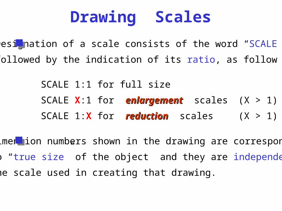
Designation of a scale consists of the word “SCALE”
followed by the indication of its ratio, as follow
SCALE 1:1 for full size
SCALE X:1 for enlargementenlargement scales (X > 1)
SCALE 1:X for reductionreduction scales (X > 1)
Dimension numbers shown in the drawing are correspond
to “true size” of the object and they are independent of
the scale used in creating that drawing.

Basic Line Types
Types of Lines AppearanceName according
to application
Continuous thick line (HB) Visible line-finishing
Continuous thin line (H) Dimension line
Extension line
Leader line
Hatching line
Dash thick line (HB) Hidden line
Chain thin line (H) Center line
NOTE : Dimensions in mmWe will learn other types of line in later chapters.
3 1.5
6 1.53

Basic Line Types-cont
Types of Lines AppearanceName according
to application
Arrows Heads (HB) Arrows
NOTE : Dimensions in mmWe will learn other types of line in later chapters.
Cutting line (HB) Section line
6 1.53
5 - Units
2 - Units

Visible linesVisible lines represent features that can be seen in the
current view
Meaning of Lines
Hidden linesHidden lines represent features that can not be seen in
the current view
Center lineCenter line represents symmetry, path of motion, centers
of circles, axis of axisymmetrical parts
Dimension and Extension linesDimension and Extension lines indicate the sizes and
location of features on a drawing

Example : Line conventions in engineering drawing

End of Lecture 1
Overview of an Engineering Drawing