engineering - americanradiohistory.com...customer's specifications in dry or oil- filled types...
TRANSCRIPT

u n ¡cal ionßroad cas
Engineering
rio Telegraphy
dio Telephony
e and Cable -graphy
e and Cable :phony
`adcast nsmission
ier smission
m Ismission
rine Radio
ice Radio
ronautical Radio
evision
-simile
SUBSCRIPTION
$3.00 YEARLY
Irmo RIP.
The Journal of World Communication www.americanradiohistory.com

A COMPLETE LINE -FILLING' EVERY BRO DCASTING NEED
Model SR -80. Easiest way to improve any installa- tion. Perfect fidelity. No background noises. No resonant peaks. Can be placed up to 2000 feet from amplifier without any appreciable loss. Frequency response 30 to 10,000 C.P.S. Output, -64 db. (open line). Hand -hammered ribbon is not affected by even a 40 -mile gale. Not affected by tempera- ture, pressure, or humidity. Com¡iptely shielded. Elastic coupling absorbs shocks Mid vibrations.
Model RB -M New Super -flux Nickel Aluminum Magnets are used ... magnets more power- ful than even 36% Cobalt .. .
Since this microphone has no peaks, it gives perfectly life- like reproduction (not mechan- ical) and does not tire the listener. Eliminates acoustic feedback in F.A. Work. NEW! High Level Model RB -H. Elim- inates separate pre -amp. (Out- put impedance, 2000 ohms.)
TRANSFORMER COUPLED THOROUGHLY SHIELDED 6, GUARANTEED HUMLESS Also included in FREE TRIAL offer. Frequency range, 30- 14,000 cycles (1 db.). Hum
level, -100 db.
NEW! HighLevel Model SR8O-H. Unusual brilliancy and definition. Eliminates input transformer with its losses and inductive hum. Requires 15 db. less overall amplification than low impedance type. Ex- cellent for both udio and remote. This microphone is high enou impedance (2000 ohms) to oper- ate directly grid -but not high enough to in- troduce seri losses in lines up to 50'. Longer lines can b d with low capacity R.F. Cable.
Broadcasts rs are invited to conduct a TW D WEEKS' FREE TRIAL of our microphones. No deposit. No obligation whatever. All we ask is that you make the test exhaustive. Then decide whether you want to keep the microphone or return it. Even it you are not in the market. feel free to make the test for future reference. Behind this FREE TRIAL offer is the conviction that Amperite offers the finest microphones available today. regardless of price. High fidelity reproduction of speech and music.... Perfect Definition of instruments in ensemble work.... Dependability .. Ruggedness ...
AU these qualities are gxaranteedl
THE LITTLE VELOCITY WITH UNIFORM OUTPUT
Output uniform with speaker's head at any angle Output level practically equal to large velocity. Frequency response 60 -7500 cycles. Reproduction lifelike Eliminates audience noises Transformer included within microphone case. Rug- ged construction New chrome aluminum magnets used Weighs only 8 ounces Size 21/4 x 11/4 x 1% High Level Model available (Model 7J -H)
The very latest in construc- tion and appearance Rug- ged Smooth operating Complete line of floor stands. Desk and banquet stands. Portable stand which un- folds to extra sturdy floor stand. Chrome or gunmetal finish. Write for Bulletin S.
NEW! Illustrated Catalogne Sheets.
Write for them now.
VELOCITY AJ4ERJ7"E MICROPHONES
AMPER/TE Cmpany_ 561 BROADWAY NEW YORE
Cable Address Alken, New York
www.americanradiohistory.com

AUDIO POWER and FILTER UTC gjç1COMPONENTS
BROADCAST for HIGH POWERED
TRANSMITTERS Typical UTC units used in better equipped
i 3 II High Fidelity Broadcast Stations
'.
t
'to, ..
---__ _ : a
a
fr' '¼
o,
N.
The units illustrated -top row, left to right -are: an oil -filled class B output transformer; plate transformer for output and RF stage; oil -filled modulation reactor. Second row, left to right: audio and filter reactors. Bottom row: speech and voltage amplifier audio units, etc.
UTC specializes in custom -built audio transformers in power ranges of 120 DB. to 50 KW.; power transformers to customer's specifications in dry or oil- filled types from I watt to 100 KVA. -up to 100,000 volts.
UTC has set a new precedent in matched audio units used by high fidelity broadcast and communication systems.
UTC LINEAR STANDARD and HI -PERM ALLOY audio transformers are calibrated and guaranteed to be -I DB. from 30 cycles to 20,000 cycles. All pertinent technical data and frequency response in DB. indelibly imprinted on outer trans- former shield for customers' protection.
UTC HIPERM ALLOY Audio .. used in the new Transformers
alti illj_ WOR TFfrA .e
30B Portable Amplifiers, specially
'7k'' .t -di h 15`t built for use in remote Pickup
H :7/. ..;r':: -.'f' broadcasts in conjunction with the h¡ iJ. new WOR high fidelity 50,000 -watt ' .
transmitter.
Write for the U 1008 bulletin describing the use of Linear Standard Units in amplifier circa having an outpu- of from 1/2 watt to 000 watts. Also includes Decibel, Reactance and Resistance data , 'a-'..
UNITED TRANSFORMER CORP. Export Division: 15 Laight Street, New York City
74 -78 SPRING STREET NEW YORK, N. Y.
OCTOBER
I935 COMMUNICATION AND BROADCAST ENGINEERING 3
www.americanradiohistory.com

OCTOBER 1 9 3 5
EDITORIAL
11.%11111 .H'..-, BAN?
4 OCTOBER
1935
DURING THE ANNUAL convention of the In- land Daily Press Association, held the week of October 14th, a resolution was adopted urging the Federal Communications Corn - mission to ban news flashes broadcast under the sponsorship of radio advertisers.
A reading of the resolution provides rea- sons for this suggested muzzling of radio commentators, such as, to "preserve the true news value" ; for the protection of the radio audience ; as a precaution against the coloring of news by advertisers.
It was pointed out that the U. S. postal laws prohibit newspapers from printing "any editorial or reading matter for which money or other valuable consideration is paid un- less it is plainly marked `advertising.' "
The suggestion was made that all news broadcast should be only in the form of an unsponsored editorial from the broadcast- ing station itself.
In the resolution the hope was expressed that all newspapers and news -gathering organizations would cooperate in developing a satisfactory plan for the broadcasting of news bulletins as "a public service in the name of the participating groups."
This resolution has all the earmarks of a rather clever counterplay. If sponsored news flashes are banned, the Fourth Estate will be on the road to a complete control of news distribution -at the expense of the Broadcasting Industry.
The inference that sponsored news is "colored" or "edited" by the advertiser is unwarranted. The inference that the listen- ing public requires protection from errors or exaggerations is also unwarranted. The suggestion that the broadcasting of news should conform to the U. S. Postal Rules and Regulations is not only unreasonable, but decidedly incongruous. The controlling body is the Federal Communications Com- mission, and any interference on the part of another government agency would only
weaken the supervising power of the F. C. C. and tend to reduce its efficiency.
The resolution referred to was no doubt prompted by an increasing feeling of un- easiness on the part of newspaper pub- lishers, who see in the human and dramatic appeal of the radio news commentator a menace to printed news. His growing pop- ularity with the radio audience is indicative of the value and interest the public places in radio news flashes.
Should broadcasters lose their right to transmit news flashes, they will have lost the strongest link between their stations and the listening public. Radio news re- porting has not been developed to its full technique, but in time its importance may well overshadow program transmission. It is vital, therefore, that the broadcaster retain his rights in the matter.
Broadcast stations are the logical mediums for the distribution of spot news ; first, be- cause of the rapidity with which the news can reach the public ear ; second, because of the huge number of people reached ; and third, because of the human interest and drama that can be packed into each flash. All three points have vast sociological sig- nificance, and we doubt if a public keenly in- terested in maintaining a close and human contact with the activities in this world, would for a moment approve of a ban were they given the opportunity of expressing their views.
The question is: what are the broad- casters going to do about it? It is high time that a complete and unconditional agreement be made between broadcasters and newspapers in regard to what each agency shall do in the future. It is natural that the newspapers should wish to protect their in- terests as they see them, and it is equally as natural that the broadcasters should wish to expand upon the types and forms of ser- vices they are in a position to provide. But it is not reasonable that newspaper publishers and the news -gathering agencies should at- tempt to retard the growth of broadcasting by depriving the public of a desired service.
COMMUNICATION AND BROADCAST ENGINEERING
www.americanradiohistory.com

ANOTHER REASON
WHY
BLAW -KNOX RADIATOR INCREASES NIGHT TIME COVERAGE 50 MILES
FOR STATION W H O From the Central Broadcasting Company Station WHO,
Des Moines, Iowa, comes the following comment:-
"We would like to commend your company on the tower installation which you
made for the Central Broadcasting Company Station WHO Des Moines. We
have every reason to believe that from a radio standpoint this tower has given
us a signal strength increase equivalent to the best tower installation in this
country, increasing our field at one mile from approximately 1500 to 1900 mv, m,
and increasing our fading wall distance approximately 50 miles.
Again let us thank you for your wonderful cooperation in providing us
with the means for greatly increasing our coverage."
WHO -DES MOINES PAUL A. LOYET, Technical Director
May we send you our recommendations and approximate prices on Blaw- Knox Radiators to increase the effectiveness of your own coverage. There are now 446 Blew -Knox Vertical Radiators in use.
BLAW -KNOX COMPANY 2065 FARMERS BANK BUILDING PITTSBURGH, PA.
H A M M A R L U N D Trimming, Padding and I. F. Tuning CONDENSERS
AMOST complete line of small adjustable con- densers -the result of ten years of specializa-
tion on the exacting requirements of the radio industry.
Isolantite or Bakelite bases; air or mica dielectric: phosphor bronze spring plates ; brass, self -aligning adjusting screws; in a large variety of sizes, shapes and ratings. Actual minimums are lower and actual maximums are higher than stated ratings. Individually tested for capacity range, power factor and for break- down at 500 volts D.C.
Special models made to specifications.
If you want condenser quality at interesting prices, put your problems up to HAMMARLUND.
i
apt, 3a#un. Rr:rlirr
4rammarlund PRODUCTS i
See the Difference Good Design Makes
Write Dept. CB -35 for Complete Catalog. Sena specifications for quotation on special designs.
HAMMARLUND MFG. CO. 424 -438 W. 33rd St.. New York
Export Dept.-15 Leight Si., N.r York, U.S.A.
OCTOBER
I935 COMMUNICATION AND
5 BROADCAST ENGINEERING
www.americanradiohistory.com

C TO OPERATE
DIRECT CURRENT
QUIPMEA
THESE Ward Leonard Controlled Rectifiers, without moving parts, offer a most economical means of providing direct current from alternating current supply. They operate with little electrical and no mechanical loss. They require no mainte- nance. Here is the device you have been looking for to operate your DC equipment from AC cur-
rent where volt- age control is a factor. Send for particulars.
CONTROLLED RECTIFIERS for communi- cation, laboratory and similar uses requir- ing a constant DC voltage with varying loads.
SEND FOR DESCRIP7IVls BULLETIN Bulletin 8601 describes the II'ard Leonard Controlled Rectifier, gives efficiencies and other technical data. Send for a copy.
WARD LEONARD RELAYS - RESISTORS - RHEOSTATS
WARD LEONARD ELECTRIC CO. 33 South Street, Mount Vernon, N. Y.
Please send me your bulletin No. 8601.
Name
Company
Vtreet
City and State...
6 OCTOBER
1935
MIN
THE NEW ANSLEY DYNAPHONE Plays 16 -inch Records Excellent for broadcast transcription records and all smaller discs of any speed. Microphone jack provided. AC -DC. Crystal pick -up (patented). Weighs 35 pounds. $89.50, ready for use.
ANSLEY RADIO CORP'N 100 West 57th Street New York, N. Y.
Performanre- whether in men or machines, de-
pends on reliability and trustworthiness. Today, engineers strive for that extra margin of safety which assures reliable operation. Breakdowns and tie -ups are taboo.
WORKING VOLTAGE 20 V. D.C.
t.e. ,..
cei. .
sa.
500 1000 1500 2000 2500 3000 4000 5000
EVL-2005 EVL4010 EVL-2015 EVL.2020 EVL2025 EVL.2030 EVL-2040 EVL-2050
NxWxD
g - s I/ . dsS.lf2 D - s1/4S1/4a2;'. E p/la .3 F - 41/4.4 .4
The same care tul selection of
materials, the same meticulous inspection
of products and ad- vanced production methods that characterize the famous and widely accepted Dubilier mica transmitting condensers are in- corporated in the CoaNEl.l.- Ucaataa electrolytic condensers.
A complete line of high capacity. low voltage electrolytic. are avail -
able. Specially designed for use in all uni -direetional or direct current applications. When extremely high capacity is required in circuits. where the D. C. working voltages do not d 50 volts.
Engineering catalog. No. 127 and 12+1. Illustrating a complete line o1 lertrnlvl i , mica. paper and i. eondes,, now available.
CORNELL-DUBILIER CORPORATION
4398 BRONX BOULEVARD NEW YORK
COMMUNICATION AND BROADCAST ENGINEERING
www.americanradiohistory.com

COMMU IICATI10
IENGE\
N & I13IR.OADCAS
IEIERR \G
FOR OCTOBER, 1935 pr.,- 14 tooZ
f' cri.
A NEW METHOD OF MEASURING STUDIO REVERBERATION
DECAYING SOUND WAVES 111 a room pre- sent an interesting problem in measure- ment. The particular combination of
apparatus necessary for such measure- ments is unique in requirements and function. The following description deals with a novel system employing some of the most modern tools of the art and yet yielding a simple, direct result. A cathode -ray tube forms the basis around which the system is built.
SOUND IN CONFINED SPACE
Whenever a sound wave is produced in a confined space there is formed a complex pattern of direct and reflected waves the vector sum of which at any point creates an instantaneously unique value of sound pressure. While the sound source is vibrating, the reflected waves add to the direct wave produc- ing an increase or decrease in pressure depending on the relative phases but always increasing the average sound pressure in the space. When the sound source ceases to vibrate, the sound waves existing at that instant gradually dissipate themselves upon the confining areas. The rate at which this dissipa- tion takes place is a characteristic of any particular space and since it is in general a function of frequency, its measurement must be performed at a sufficient number of frequencies as to completely determine this function.
OCTOBER
935
By ALFRED W. BARBER
CONSULTING ENGINEER
Resume of Data Obtained in Studios of W2XR, and the Equipment Used
MEASURING SET -UP
Fig. 1 shows a block drawing of the present system for measuring the rate of sound decay at various frequencies. A beat oscillator is used to generate an audio tone of any desired frequency. The audio -frequency voltage is ampli-
BLOCK DRAWING OF
THE SYSTEM USED
FOR MEASURING THE
RATE OF SOUND DE-
CAY AT VARIOUS FREQUENCIES.
feed and fed to a loudspeaker located within the space where measurements are to be made such as a broadcasting studio. living room or auditorium. The loudspeaker sets up the desired sound wave and is turned off and on by a pair of motor- driven contactors. The sound pressure in the space is converted into
Beat Oscillator
Wobble Tone
Synchronous -- Motor
Sweep Generator
Fiq.t
Amplifier
Cam
/!,
Cathode Roy Tube'
Speaker
Ft 1,
Room
Microphone
Ampi fier
COMMUNICATION AND
BROADCAST ENGINEERING 7
www.americanradiohistory.com

electrical oscillations by a high -grade microphone. The electrical energy is then amplified and indicated on a ca- thode -ray tube. If the amplifier output is applied, as shown, to the vertical de- flecting plates, the beam excursion in the vertical direction will indicate the sound pressure amplitudes existing at the microphone. A condenser charged at a constant rate is connected across the horizontal deflecting plates of the cathode -ray tube, thus creating a time axis for the sound pressure. A second set of contactors on the motor is actu- ated by the same cam which operates the speaker and removes the short from the deflecting condenser, thereby start- ing the beam across the screen.
OPERATION In operation, the motor is started and
for part of a revolution connects the speaker and returns the cathode -ray tube beam to one side of the screen. The speaker, actuated by the amplified beat - oscillator output, builds up a sound pat- tern. The speaker is silenced by open- ing its circuit and at the same instant
the cathode -ray beam is started across the tube at a uniform rate of speed. The vertical deflection records the de- cay of sound against the horizontal time axis. A camera may be conveniently used to record this pattern and the results may be computed from the pho- tographs.
By definition "reverberation time" is the time required for the free sound pressure in any given space to fall 60 db. On a cathode -ray tube it is difficult to measure a 60 -db range, but since the decay function is closely logarithmic, the result may be obtained by taking three times the time required for a 20 -db decay of sound pressure. The accuracy of the results thus obtained seem to fully warrant the extrapolation.
MEASUREMENTS IN W2XR STUDIO The above apparatus was used to
measure the characteristics of a studio being used by the high -fidelity broad- casting station W2XR in New York. The studio under investigation has a floor 15 feet by 15 feet and is 10 feet high. The walls are covered with half-
FREQUENCY: 30 CYCLES. TIME: 0.38 SECOND.
FREQUENCY: 60 CYCLES. TIME: 0.44 SECOND.
FREQUENCY: 160 CYCLES. TIME: 0.24 SECOND.
FREQUENCY: 450 CYCLES. TIME 0.24 SECOND.
FREQUENCY: 700 CYCLES. TIME: 0.24 SECOND.
FREQUENCY: 1000 CYCLES. TIME: 0.23 SECOND.
FREQUENCY: 1500 CYCLES. TIME 0.18 SECOND.
FREQUENCY: 4000 CYCLES. FREQUENCY: 6500 CYCLES. TIME: 0.12 SECOND. TIME: 0.12 SECOND.
r 1.0
1 6
Ito .4
``z I 1 11
88 8 8 88 §
Frequency in Cycles
Fig. 3
RESULTS OF MEASUREMENTS MADE IN A STUDIO AT W2XR.
inch Celotex backed by rock wool for sound insulation purposes. Two walls and the ceiling are covered with Monk's Cloth having a fifty percent gather. The main furniture in the studio consists of two grand pianos with benches, and four small chairs. This studio is used for solo and duo piano work, solo and duet singing, violin and piano, and violin, 'cello and piano combinations.
The measurements to be described in this report were made with steady tones of frequencies from 30 to 6500 cycles. Higher frequencies will be used in later tests as the upper limit by the present method is determined only by the speaker used as a sound source.
MEANS OF MEASUREMENT
In making these measurements an audio- frequency beat -oscillator output was amplified by the station monitor amplifier and the output fed to a high - fidelity speaker located within the studio. The sound pressure produced was picked up by means of a special crystal microphone. The microphone output was amplified by the regular sta- tion pre- amplifier and main amplifier. The main amplifier output was indicated vertically on the screen of a three -inch cathode -ray tube.
The horizontal cathode -ray tube de- flection was obtained from the voltage across a condenser charged at a constant rate through a current -limiting tube. The beam speed was determined by photo- graphing it against a 60 -cycle voltage. The speed thus determined was 15 cm /sec. The speaker was turned off and the cathode -ray tube beam started by means of a double contactor actuated by a cam driven by worm -gear reduc- tion from a 3600 -rpm synchronous mo- tor. A 9 by 12 cm camera having an aperture of f 4.5 and a double extension bellows was used to photograph the ca- thode -ray tube traces on verichrome film.
RESULTS OBTAINED
Fig. 2 shows the results obtained over the range from 30 to 6500 cycles. It will be noted that the decay curve is not smooth, but goes through a series
(Continued on page 21)
8 OCTOBER COMMUNICATION AND 19 3 5 BROADCAST ENGINEERING
www.americanradiohistory.com

MARINE RADIO - TELEPHONE SERVICE
SINCE THE ESTABLISHMENT of ship -to- shore radiotelephone service by the Bell System in 1929, there has been a con- stantly increasing interest in a similar but less expensive service for small har- bor and coastal craft such as tugboats, private yachts, coastal passenger ships, merchant craft and fishing vessels. This interest became particularly evident in New England in 1931 and since equip- ment suitable for the purpose had re- cently been developed by Bell Telephone Laboratories, the New England Tele- phone and Telegraph Company under- took the establishment of a marine ra- diotelephone service.
A survey consisting of a comprehen- sive series of field- strength measure- ments on ship board and at various
By F. A. GIFFORD and R. B. MEADER
Engineering Department
NEW ENGLAND TELEPHONE & TELEGRAPH CO.
points along the coasts of Massachusetts and Cape Cod Bays resulted in selecting Green Harbor as the location for a shore station. Green Harbor is in the town of Marshfield, Mass., about 28 miles southeast of Boston.
A commercial survey indicated that initially the service would be of interest chiefly to the Boston fishing industry. Consequently boat radiotelephone equip- ment was installed on the trawler Flow of the Bay State Fishing Company and the service was opened in June, 1932, on a demonstration basis. As tests with this vessel progressed, it became evident that the radiotelephone service would fulfill the communications requirements of the fishing industry. It also became apparent that a complete service of this
OCTOBER
I935
VIEW OF THE GREEN HARBO R STATION, MARSHrIELD. MASS.. THE SENDING AND RECEIVING POINT IN THE NEW ENGLAND MARINE RADIOTELE
PHONE SYSTEM.
type should include some means for de- termining the vessel's position at any time by means of radio.
Fishing operations are usually con- ducted in areas requiring accurate bear- ings over distances as great as 200 or 300 miles from shore radio- beacon sta- tions. Equipment was developed to per- form that function as an adjunct to the radiotelephone service. Tests of an ex- perimental model indicate that the prob- lem of providing suitable radio -compass equipment in the price range satisfac- tory to the fishing fleet owners has been satisfactorily solved.
During the period required for the development and tests of the radio com- pass, radiotelephone equipment was in- stalled on several other fishing craft and on one private yacht and the service was placed on a commercial basis on July 1, 1934.
RADIOTELEPHONE EQUIPMENT (Shore Sfa +ion)
The shore terminal at Green Harbor (Station WOU) comprises in general a radio transmitter with associated an- tenna and power supply, a radio receiver with its associated antenna, and voice - frequency terminal equipment for main- taining proper speech volumes, prevent- ing echoes and singing and providing for monitoring, talking and signaling. All the equipment is of Western Electric make.
The transmitting antenna is a single vertical wire 120 feet in height sus- pended from cables extending from three 165 -foot steel towers 500 feet apart to a common point above the station. Ad- vantage was taken of three towers al- ready in existence.
The radio transmitter is a 400 -watt, crystal- controlled type similar to those designed for use at aviation ground sta- tions and adjusted to operate at a fre- quency of 2506 kilocycles. This fre-
COMMUNICATION AND BROADCAST ENGINEERING 9
www.americanradiohistory.com

quency is maintained within limits of
better than 0.025 percent. The power supply for the transmitter is obtained from a rectifier consisting essentially of two three -phase and a single -phase rectifier operating on 220 -volt, three - phase, 60 -cycle power.
The transmitter is coupled to the an- tenna by means of a 500 -ohm transmis- sion line and a tuning unit containing the necessary apparatus for tuning the antenna to resonance.
The radio receiver is of the double - detection, single -control type, equipped with automatic volume control and ar- ranged for operating over a frequency range of from 1500 to 3600 kilocycles. The receiver is coupled through a con- centric conductor transmission line and tuning unit to a single vertical -wire re- ceiving antenna 45 feet in height located 500 feet from the transmitting antenna.
In order to combine the two uni- directional radio channels into a two - way circuit suitable for connection to the ordinary wire circuits in the land telephone network, apparatus similar to that provided at the terminals of the transatlantic and high seas ship -to- shore radiotelephone circuits has been provided. This apparatus includes con- trols for adjusting the volume of speech into the transmitter and from the re- ceiver to the wire lines and the usual voice -operated devices (termed "vo- das") provided for the suppression of echoes and singing.
The apparatus mentioned, together with a volume indicator, means for talk- ing, monitoring and signaling, and test- ing apparatus is assembled on one floor - mounted apparatus bay. This, mounted adjacent to the bay containing the re- ceiver and a noise- suppression device constitutes the operating position. This position is continuously attended by a
OCTOBER
1935
CABINET ASSEMBLY OF MARINE RADIO- TELEPHONE EQUIP- MENT, HOUSING COM- PACTLY THE TRANS- MITTER (UPPER LEFT), THE RECEIVER )UP- PER RIGHT). AND BELOW THE JUNC- TION BOX AND SE- LECTOR SET. THE LATTER AN OPTIONAL FEATURE FOR EX- CLUSIVE RINGING OF
THE VESSEL'S TELE- PHONE BELL.
technical operator who adjusts the con- trols during the progress of each call, guided by indications of the meters pro- vided, to insure the best possible con- nection under the conditions obtained at the time. Power for the terminal appa- ratus is supplied by a motor -generator set operating from a 110 -volt 60 -cycle source.
A noise- suppression device, termed a
"codan"* (carrier -operated device anti -
noise) is employed in connection with the receiver to insure relatively quiet conditions on the receiving line by in- troducing a predetermined high loss into -*See
page 20.
MARINE RADIOTELEPHONE EQUIPMENT FOR HARBOR CRAFT. TRAWLERS AND
YACHTS.
the audio -frequency portion of the radio receiver during intervals when there is no incoming carrier. When a carrier is received, the codan action removes this loss, allowing the speech with which the carrier is modulated to pass from the receiver output to the receiving line. This device makes it possible to deliver higher speech volumes to the telephones on shore since it prevents the operation of the receiving vodas relays on radio noise during the idle intervals. It also prevents the high radio noise which would otherwise result due to the in- crease in gain inserted by the automatic volume control whenever the carrier is
interrupted. It can be seen from this discussion
that the codan requires that the carrier of the distant transmitter be suppressed, except when the user actually talks. This method of operation has been adopted for this type of marine radiotelephone service.
A 10 -kw, 220 -volt, three -phase, 60- cycle alternator, driven by a Buffalo gasoline engine, has been provided to furnish the necessary emergency power supply in case the normal commercial supply fails.
RADIOTELEPHONE EQUIPMENT (Boat Stations)
The boat station equipment consists essentially of three units: A steel cabi- net, 28% inches by 251/2 inches by 25
inches, containing the radio transmitter, receiver, signaling unit and relays for controlling the circuit operating, the power -supply equipment, and a control unit including a handset of a special
COMMUNICATION AND
BROADCAST ENGINEERING
-
www.americanradiohistory.com

type. The details of the radio -compass equipment are not within the scope of the present article.
The boat station radio transmitter is a 50 -watt crystal- controlled type in which the crystal operates at half the carrier frequency. The transmitter is arranged for the use of three carrier frequencies, any one of which may be selected by means of a single local me- chanical or an electrically -operated re- mote control. The frequency designated by the Federal Communications Com- mission for use by ships communicat- ing with the shore through the Green Harbor radiotelephone station is 2110 kilocycles. This carrier frequency is maintained within limits of 0.025 per- cent. The equipment for coupling the transmitter to the antenna and tuning it to resonance forms an integral part of the transmitter.
The radio receivers most recently in- stalled are of the superheterodyne type with the frequency of the beating oscil- lator crystal controlled to insure that the receiver is always adjusted to the proper frequency. Two crystals are provided and the circuit arranged so that the re- ceiver may be quickly adjusted to oper- ate on either of two frequencies by means of a local mechanical or an elec- trically- operated remote control. The second receiver frequency makes possi- ble boat -to -boat conversations on a sepa- rate frequency.
The signaling unit which is normally connected to the output of the radio receiver consists of a selector operated under the control of an arrangement of relays which in turn are controlled by incoming signal pulses of 600- and 1500 - cycle tones. The bell on each vessel is operated only in response to the par- ticular code of pulses to which the se- lector is adjusted. Arrangements are also included so that all the vessels of any one fleet may be called simultane- ously.
The power- supply equipment depends upon the characteristics of the vessel's primary electrical power, but d -c volt- ages of 1050, 200 and 12 volts are neces- sary for the operation of the radio equipment. In the case of a vessel with a well regulated 110 -volt power plant, power at the above voltages is furnished by two motor -generator sets equipped with speed regulators.
One of these motor- generator sets op- erates continuously while the vessel is standing by for the reception of signals and furnishes 12- and 200 -volt power for the operation of the radio receiver and signaling unit. The second motor - generator set is automatically started when the handset is lifted from the switch hook to place a call or in re- sponse to an incoming signal, and fur- nishes power to operate the transmitter.
OCTOBER
1935
INTERIOR VIEW OF THE GREEN HARBOR STATION. MARSH -
FIELD. MASS.. THE SENDING AND RE- CEIVING STATION IN THE NEW ENGLAND MARINE RADIOTELE
PHONE SYSTEM.
On several of the smaller boats having 32 -volt power supply with wide voltage fluctuations, power -supply equipment consisting of two dynamotors operated from a 12 -volt battery charged from the vessel's storage battery has been em- ployed successfully.
The control unit for the radiotele- phone consists of a small panel on which are mounted a switch for turning the set on and off, a meter for indicating antenna current, a manual volume con- trol, pilot lamp signals and a bell for announcing incoming calls. A special handset with push button completes the control unit assembly.
OPERATING POSITION AND WIRE LINES
At Boston, the marine radiotelephone traffic is handled at two positions on the outgoing toll board especially modified for this purpose. The wire lines from the Green Harbor station terminate at this point, and calls from vessels can he switched by the operator to any point connected to Bell System facilities. The normal wire lines are three loaded cable pairs. One pair is used for transmis- sion from the shore telephone to a boat. the second conducts speech received from a boat through the toll position to the land -line telephone, and the third is employed as an order wire for com- munication between the operator at the marine position and the technical oper- ator at the Green Harbor station. All of these circuits are duplicated over an alternate route for use in case of trouble on the normal facilities.
OPERATION OF THE SYSTEM
To illustrate the operation of the ser- vice, let us follow the routing of a call from an ordinary land telephone to a vessel and vice versa. Let us assume that a person in the vicinity of Boston wishes to talk with the captain of a fishing trawler. This person follows the usual procedure in placing a tele- phone toll call. The toll operator estab- lishes connection with the marine oper- ator who records the details of the call and requests the person calling to hold the line.
The marine operator then dials the code assigned to the vessel desired. The dialing operation produces the desired grouping of 600- and 1500 -cycle pulses which modulate the radio -transmitter carrier frequency of 2506 kilocycles. The signaling unit on the vessel is actu- ated by these pulses and the bell rings. The captain raises the handset from the switchhook on the control unit, presses the push button in the handle of the handset and announces the name of his vessel. The operator then completes the connection and the conversation ensues.
In placing a call from boat -to -shore the captain or member of the crew raises the handset from the switch -hook and, after listening to ascertain that no con- versations are in progress, presses the push button and calls "marine opera- tor." The marine operator who is nor- mally monitoring on the channel ascer- tains the name of the calling vessel, the
(Continued on page 15)
COMMUNICATION AND BROADCAST ENGINEERING
www.americanradiohistory.com

INTRODUCTION
AS BROADCASTINC IIAS advanced, the technical requirements have become more exacting in every way. The rule of thumb has had to give way to exact engineering. This is particularly true in regard to the radiated energy from a radio transmitter. Quantitative mea- surements of this radiated energy is usually expressed in terms of field strength.
Field strength measurements can be naturally divided into two distinct classes; namely, spot measurements and continuous recording measurements. A readily portable, rugged, yet easily -oper- ated instrument is desirable in making spot measurements, while continuous recording equipment may be of a semi - portable type, but capable of operating for long periods of time without much attention.
To meet these requirements, two measuring sets were designed and con- structed. Both sets have proven to be very satisfactory in field operation. Some of the needs and applications with a description of the equipment follows:
PORTABLE FIELD STRENGTH SET
Commercial departments find it neces- sary to call upon the technical depart- ment to help solve the question of cov- erage so that equitable rates can be established. The equipment needed to accomplish this can become a very valu-
Technical Supervisor, WHK. tAssistant Engineer, WHK.
12 OCTOBER
L 1 9 3 5
FIELD STRENGTH
FIG. 2. SHOWING THE LOOP FIX- TURE EXTENDED THROUGH T H E
REAR WINDOW OF THE CAR.
By E. L. GOVE* and C. E. SMITHt
SOUND SYSTEMS, INC.
able asset to any progressive station, not only to collect coverage data, but also for the gaining of neces- sary information in locating new trans- mitter sites, determining the efficiency of radiating systems, and, when antenna improvements are made, to definitely check the degree of such improvements.
After experimenting with two port- able field sets certain improvements were found desirable and so, were in- corporated in the set. With portability in mind, it was built around the '30 series of battery- operated tubes, into a compact single unit, without sacrificing accuracy. Since the recording equip- ment covers frequencies from 550 kc to 20 mc, this set was constructed to cover only the broadcast band. The Direct Comparison Method of measurement was adopted, because of the speed and ease of operation. The calculation of field strength then reduces to simple multiplication. The set is capable of measuring field intensities from 5 mic- rovolts per meter to 1 volt per meter.
MECHANICAL FEATURES
The single compact field strength unit shown in Fig. 1 can be located on the deck back of the seat in a coupe, with the loop fixtures extending through the rear window, supporting the loop above the top of the car. The entire operation of the set is then handled from within the car (see Fig. 2). When not in use the loop fixture can be re-
radio
FIG. I. THE FIELD STRENGTH MEASURING UNIT. NOTE THE LOOP AND LOOP FIXTURE.
moved and stored in the back of the car, allowing the closing of the rear window.
The loop fixture, consisting of an extension tube and loop rotating hand - wheel, plugs into the back of the case. The loop in turn plugs into the top of this fixture. Two loops were con- structed with a voltage ratio of 10 to 1,
or a difference of 20 decibels. The large loop is used for low field inten- sities, and the small one for high field intensities near the transmitter. A small cap is provided to cover the loop tube when traveling from point to point, protecting the plug and wiring from dust and rain.
The field strength unit consists of a calibrating oscillator and superhetero- dyne receiver. The thoroughly shield- ed calibrating oscillator is located in the left hand end of the case. Next to it in the same case, though separately shielded, is the oscillator battery supply, followed by the calibrated output at- tenuator which feeds a standard signal into the loop circuit. The receiving set and output meter are located in the right hand end of the case. A cover lid fits over the recessed front panel to protect the meters and controls when necessary.
The receiver battery supply is in a separate case located in the rear com- partment of the car. A plug -in cable makes the connection with the set through the rear window.
ELECTRICAL DESIGN
A circuit diagram of the calibrating oscillator is shown in Fig. 3. The os- cillator consists of a push -pull circuit carefully and thoroughly shielded to prevent stray coupling into the loop
COMMUNICATION AND BROADCAST ENGINEERING
www.americanradiohistory.com

MEASURING EQUIPMENT
r r
Osc. 19
r + 3V.
Fiq. 3 c Oscillator
G coil P placement
IO Ohm concentric transmission line to receiver loop
Multiplying factor 400,000 10,000 4000 /00 40 I L_
SCHEMATIC OF THE STANDARD FIELD SET SIGNAL GENERATOR.
circuit. The oscillator coils are of the small honeycomb type mounted on an Isolantite shaft; the whole assembly ar- ranged to plug in. The coil unit is in a double -shielded compartment. Each unit o f the oscillator is separately shielded and all shields are grounded to the case at a common point. This entire assembly is enclosed in a copper case and the unit mounted inside the aluminum carrying case.
The oscillator battery supply case is constructed of copper, the grounding of which is a part of the unit system, thus preventing any possibility of stray fields through the leads. The filament voltage is controlled by a rheostat and measured by a meter on the panel.
The r -f output of the oscillator is con- trolled by a 200 -ohm potentiometer con- nected through a thermocouple, for metering, to the attenuation network. The attenuation network consists of a ratio arm and a multiplying- factor switch, making possible the control of the output continuously from 0.5 micro- volts to 1 volt. Special care was taken in the shielding of the attenuation net- work, and its attenuation was checked against a known standard.
The output of the attenuator feeds into one side of the balanced loop cir- cuit. as shown in Fig. 3. When the calibrating oscillator is connected to the loop, the resistance in each side of
OCTOBER
I.935
the loop is balanced. Half of the out- put of the loop feeds into a sensitive superheterodyne receiver using one stage of tuned radio frequency. The receiver selected was a standard battery - operated set. The automatic volume control was replaced with a stepped control, as shown in Fig. 4. The bias on the second detector was made con- tinuously adjustable so that a convenient deflection could be more readily obtain- ed on the output meter. The output stage was replaced by a phone -mon- itoring jack. A filament voltmeter and control rheostat were installed. A 500- microampere meter was connected in the plate circuit of the second detec- tor, and a shunt switch provided to change the meter to read 2.5 milliam- peres when less sensitivity is desirable. An audio choke coil was placed in the plate lead of the second detector to help iron out the effect of audio modulation on the carrier.
OPERATION
\\itli the proper loop in place, the loop and set are adjusted for maximum deflection. Neutralization of either loop is quickly accomplished by turning the loop- balancing condenser to previously adjusted stop pins. The stepped volume control and bias control should be ad- justed for a convenient deflection on the output meter. The loop is then
turned through 90° to a null position. The calibrating oscillator is turned on and adjusted to the frequency of the station being measured. The output of the oscillator is adjusted to a predeter- mined calibration reading on its output meter of 56. This supplies one volt across the attenuator. The attenuator, which is calibrated in microvolts, is then adjusted to give the same deflec- tion on the output meter as that induced by the signal being measured.
The voltage induced in the loop by the signal is then
0.1 E = hfe \Vhere E = voltage output of attenu-
ator connected to calib- rating oscillator.
0.1 E = voltage induced in the loop; the value 0.1 is the result of the 1.1 -ohm shunt across the 10 -ohm transmission line to the loop circuit.
e = volts per meter field in- tensity.
f = operating frequency in cycles. k AN
h = the effective height v of the loop in
meters. Where k = 6,2832
A = area of loop in square meters
= number of turns in the loop = 3 X 10' meters per second
the velocity of light. Changing E from volts to microvolts
and f from cycles to megacycles gives 1.82E
e = microvolts per meter F for the large loop
N
and 182E
e = microvolts per meter F for the small loop.
A table was prepared as a matter of convenience covering the channels in the broadcast band and reducing the above equations to
e = KtE microvolts per meter for the large loop.
e = 10 KtE microvolts per me- ter for the small loop.
\Vhere Kt = 1.82/f
RESULTS
The set has proven to be very satis- factory in field operation. It has been used repeatedly during had weather and measurements made during rain. The set can be put into operation on loca- tion and measurements made on one or more stations in a few minutes. If
COMMUNICATION AND
BROADCAST ENGINEERING
www.americanradiohistory.com

rp)
f s.
F
f st. Det. 32
270 Kc. 2nd. bet.
270 Kc. 30
.0024 Mfd.
Audio 30
.5 Mfd. .1 Mfd.
'f.t l.b .25Mfd. 8Mfd. Ohm Ohm
Concentric transmission line
from signal generator
Chassis ground
Fiy.4
Meg. J Mil® »M W.IVIN = u
Fcne
,---50,000 Ohms ` L .i 7500 Ohms
Det bias
.5 Meg. 20,000 Ohms
50hms f Meg.
4# for./ Storage battery
S3 A+
B-
23,000 Ohms
1 Meg.
B +22Y2 V. 3
BI- 90V. {B+ 1801
10.8 .
Ohms
53 53
Fuses -
MA
0-500,uA 0-25 MA.
the road is not too rough, observations can be made while traveling along the highway. This is particularly valuable when there are discontinuities in the conductivity or other irregularities that make it difficult to arrive at the true condition by spot measurements.*
FIELD -INTENSITY RECORDING EQUIPMENT
In checking the behavior of direc- tional arrays, securing fading data or making permanent records under any condition that may seem desirable, an automatic recording field set fills a definite need.
The set herein described was design- ed and built with the idea of attaining maximum flexibility and to cover a wide band of frequencies, viz., 550 kc to 20 mc. Although it has a maximum sensitivity of better than one my /m the sensitivity can be readily controlled to keep the readings within the paper width throughout wide variations of field intensity. Alternating- current operation through a voltage regulator makes possible continuous operation with little attention. The set is ruggedly constructed and when mounted in a car can be put in operation in a few minutes after connecting to a power supply. A 200 -ft. cable carried in a reel mounted on the rear of the car makes such a con- nection very simple.
MECHANICAL FEATURES
The equipment is divided into six portable units : (1) a calibrating oscil- lator antenna tuning unit; (2) a re- ceiver unit; (3) the attenuator unit;
'Readings taken on reenforced concrete high- ways may he in error due to the presence of stanul i ng Waves.- EDITOR.
14 OCTOBER
{ 19 3 5
SCHEMATIC OF THE STANDARD FIELD SET RECEIVER.
(4) the logarithmic voltmeter unit ; (5) the recording meter; and (6) a voltage regulator.
Each unit is assembled in a metal case equipped with carrying handle and protective metal cover. Power- supply connections are made through plug -in cables. The r -f connections are made through plug -in concentric transmission lines connecting directly from case to case when they are lined up side by side in proper order.
The loop is designed with an exten- sion column so that connection can be made through the top of the car, rota- tion being controlled from inside the car. A built -in coupling unit makes possible the use of a conventional anten- na when desired.
Each unit is thoroughly shielded so that stray fields are kept to a minimum.
ELECTRICAL DESIGN
In the calibrating oscillator antenna tuning unit a variometer and varicoup- ling assembly make possible the use of a conventional antenna. Selection of this arrangement on the loop is ac- complished through a simple transfer switch.
The thoroughly shielded calibrating oscillator is inductively coupled to the loop circuit, static shielding separating the two coils. The thermocouple for metering the applied voltage is con- nected across the primary coil. The oscillator power supply is secured from the receiver.
The receiver unit consists of a stand- ard all -wave receiver modified by re-
moving the Class B audio output sys- tem and substituting a plate -to- 500 -ohm transformer for monitoring phones. Che 53 output socket provides the fila- ment and plate supply for the calibrating oscillator.
The antenna transmission line ter- minates in a flexible lead and grid clip and can be connected to any one of three grid caps. These connections are made through a small door in the re- ceiver panel. This gives a wide range in sensitivity, hence a wide range of field strength may be measured.
The automatic volume control was removed and the input to the inter- mediate amplifier connected through a concentric transmission line to the at- tenuator unit and back through another similar line. The attenuator unit pro- vides for an attenuation of 110 db in steps of 1 db.
The output of the receiver is carried to the logarithmic voltmeter unit. A discussion of this type of voltmeter is given by F. V. Hunt in the December 1933 issue of The Review of Scientific Instruments. In this unit the grids of three type 58 tubes are connected to the elements of a type 55 tube for rectification. This current is read on an 0 -200 meter. Since the output meter requires 5 nia for full -scale de- flection, a direct -current bridge amplifier utilizing two type 56 tubes was added.
The power -supply unit to operate this assembly is an integral part of it. The output of this unit may be switched from an interval 0 -5 ma meter or to two binding posts for connection to the external recording meter.
The recording meter selected was a
COMMUNICATION AND BROADCAST ENGINEERING
www.americanradiohistory.com

standard Esterline Angus 0 -5 ma graphic recording meter.
OPERATION
With the loop in place and power turned on, adjustment is made for maximum deflection on the internal out- put meter. To prevent overloading, the proper grid is selected and the db at- tenuator used for the final adjustment. The cathode -current meter should also be turned on as a check. The zero ad- justment should normally be left on a predetermined marker. A warm -up period of 15 to 20 minutes should be al-
. lowed to stabilize the operation of the beating oscillator.
The set should be calibrated both before and after making a record. With- in limits the thermal meter in the cali- brating oscillator registers the voltage induced in the loop circuit. From cali- bration curves of the oscillator output meter the voltage induced in the loop circuit can be determined.
With an output meter reference point of 4 milliamperes the desired signal is tuned to maximum and the attenuator adjusted to as near 4 milliamperes as possible. If it is desirable to know the field strength for this deflection, nota-
Lion should be made for future refer- ence. Usually the equipment is cali- brated and the field strength calculated from the recorder chart.
After turning the loop to minimum the calibrating oscillator is turned on and adjusted to the frequency being measured. The oscillator output is brought up to 10 or 20 microamperes and the db attenuator adjusted to give 4 -ma output. If this cannot be obtained readings either side should be taken and the correct db value interpolated.
With a calibrating voltage of E, hav- ing an attenuation of A, db for a deflec- tion of 4 ma and a signal induced voltage of E, having an attenuation of A. db for a deflection of 4 ma, A, -A, gives the db above the calibrating volt- age E, due to the incoming signal E, or
E, Iì, _ --
Al - A, Anti Log -
20
Ef (1) for the field strength can be written
E, e =
hf
Substituting for h the effective height of the loop and for E, this equation can
be written 17250 E,
e = A, - A,
f Anti Log my /m 20
where E, = microvolts calibrating voltage induced in the loop circuit.
f = frequency in kc. A, = db corresponding to E,
to give 4 -ma output. A, = db corresponding to E,
to give 4 -nia output. As a matter of convenience a table
was made for all frequencies in the broadcast band which reduces the abc,ve equation to
e = Kr E,
A, - A, Anti Log
where Kr = 17250 /f. This equipment has had a quite varied
use in the field both for spot and short record use and also long record work. It has proven very useful in definitely locating the fading wall of the station, Long records of fading and heterodyne effects between distant stations showing some very interesting phenomena have been made. Continuous runs during antenna experiments provide an ac- curate record of results accomplished.
20
MARINE RADIOTELEPHONE SERVICE
(Cuntiuued jrout page 11) shore station desired and other neces- sary details, and while the calling party holds the line proceeds to call the land - line telephone and establish the connec- tion.
When a person on one boat wishes to talk with a person on another boat, the procedure in placing the call and estab- lishing the connection is the same as in the case of a ship -shore call, except that when both are prepared to talk, the tech- nical operator at Green Harbor oper- ates a by -pass key which connects the radio- receiver output to the radio-trans- mitter input without including the voice - operated device and other equipment as- sociated with the land circuits. The land line is bridged on to the circuit so that the marine operator may be advised of any difficulties which arise in carrying on the conversation.
RESULTS OF OPERATION
During the more than two years that the system has been in experimental service, the transmission results up to distances of 500 miles from the shore station have been quite satisfactory. Of course, during periods of abnormally heavy static the normal range is some- what reduced. The service is available at all times, but practically all business is handled between the hours of 8:00 A. M. and 6:00 P. M. so that the rela- tively poor atmospheric conditions
OCTOBER
1935
usually existing during summer nights do not adversely affect the radiotele- phone traffic. However, experience has indicated that calls originated during such periods from vessels within the normal range can be handled satisfac- torily. During some period of favorable atmospheric conditions experimental transmissions over distances greatly in excess of the normal range have been successfully conducted.
On fishing vessels the radiotelephone equipment is accessible for maintenance work only at the conclusion of trips which are usually of about ten (lays duration. It is obvious, therefore, that the equipment must be designed for re- liable operation over long periods and experience indicates that these require- ments have been well satisfied.
Fishing craft normally make use of the service for reporting the details of the catch, for making arrangements to return to port and for talking with other fishing vessels to locate points where fishing is best. The radiotelephone has proved of vital importance on several occasions where engine breakdowns ne- cessitated advice from shore in order to make repairs and having replacement parts available upon the vessel's arrival at port. In several instances of sickness and accidents to members of a crew, medical advice has been obtained or the Coast Guard summoned to remove the injured man for quick transportation to a hospital. In one case of severe dam- age to a trawler as a result of a col-
lision, the Coast Guard were summoned and the owners were able to keep in constant touch with the situation.
At the present time, radiotelephone installations have been made on fishing trawlers and yachts, as well as on one Coast Guard patrol boat. Results of the marine radiotelephone system have dem- onstrated that the advantages offered by this type of communication service have great value both in the preservation of life and property and in the efficient operation of marine business.
CORRECTION ON PAGE 25 of the August, 1935, issue of COMMUNICATION AND BROADCAST ENGINEERING, the first sentence under the heading Hamilton, Ohio, to Install Two -Way Police Radio reads : "The first two -way police radio system in the state of Ohio will be installed this sum- mer by the city of Hamilton." This statement is not correct.
A two -way police radio system was installed by the Radio Engineering Lab- oratories in the city of Springfield, Ohio, during August, 1934. This sys- tem consists of a 50 -watt fixed trans- mitting station and nine radio -equipped police cars, with one spare for emer- gency service. Satisfactory two -way communication is carried on within the city limits, while the fixed transmitter is able to send out messages considera- bly beyond the county lines. This sys- tem has given very satisfactory service (luring its 14 months of operation.
COMMUNICATION AND BROADCAST ENGINEERING 15
www.americanradiohistory.com
WSPD Builds Nerv Stations By GEORGE BROWN
ON AUGUST 20th WSPD, a CBS basic outlet, and the only radio station in northwestern Ohio, increased its power when it put into service the latest type Western Electric 5 -kw, high -fidelity transmitter using 2500 watts daytime and 1000 watts night -time power.
The transmitting site, which was formerly located on the Commodore Perry Hotel in downtown Toledo, is now located on Oregon Road in Wood County, Ohio, about 3.5 miles south- east of downtown Toledo. The studios and offices remain in the penthouse atop the Commodore Perry Hotel.
The present site was chosen in the fall of 1934 after Mr. J. H. Ryan, Vice - President and Manager, and Mr. Vernon C. Alston, Chief Engineer, of the Toledo Broadcasting Company made a careful survey of the territory surrounding Toledo. Two field- inten- sity surveys were conducted by Jansky and Bailey, consulting engineers, at Washington, D. C., before the present site was finally decided upon and con- struction begun.
Mr. Alston designed the transmitter house and installed the transmitting equipment. Assisting Mr. Alston in in- stalling the transmitter were William Stringfellow, Phillip Bloom, Ralph Lar- son, Edward Goon, Kenneth Neubrecht, and the author; members of the WSPD engineering staff.
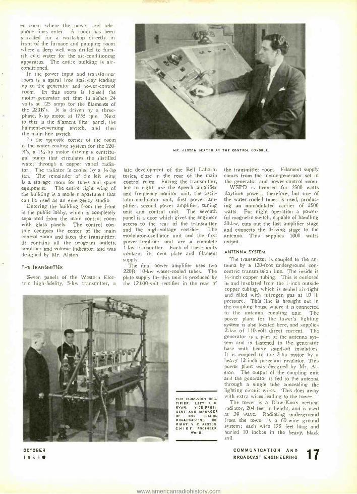
POWER AND TELEPHONE FACILITIES
Power lines carrying three -phase, 60 -cycle a -c at 6900 volts are fed from two different directions meeting at a sub -station in one corner of the five -acre plot. There it is stepped down from 6900 to 220 volts at three phase, sup- plying approximately 33 kw to the transmitter. One 10 -kw transformer supplies power for lighting the building. In emergency or failure of regular power supply, the engineer on duty may press the second power line into use by manual switching at the sub- station. The transmitter is connected to the downtown studios with two high -fidelity program lines equalized within one db from 30 to 8000 cycles.
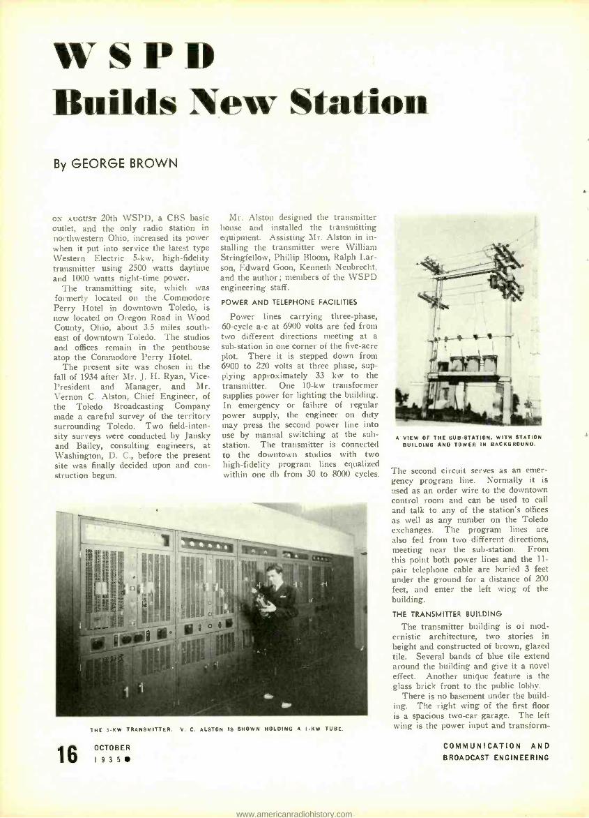
THE 5 -KW TRANSMITTER. V. C. ALSTON IS SHOWN HOLDING A I -KW TUBE.
16 OCTOBER
I935
A VIEW OF THE SUB -STATION. WITH STATION BUILDING AND TOWER IN BACKGROUND.
The second circuit serves as an emer- gency program line. Normally it is used as an order wire to the downtown control room and can be used to call and talk to any of the station's offices as well as any number on the Toledo exchanges. The program lines are also fed from two different directions, meeting near the sub -station. From this point both power lines and the 11-
pair telephone cable are buried 3 feet under the ground for a distance of 200 feet, and enter the left wing of the building.
THE TRANSMITTER BUILDING
The transmitter building is of mod- ernistic architecture, two stories in height and constructed of brown, glazed tile. Several bands of blue tile extend around the building and give it a novel effect. Another unique feature is the glass brick front to the public lobby.
There is no basement under the build- ing. The right wing of the first floor is a spacious two -car garage. The left wing is the power input and transform-
COMMUNICATION AND
BROADCAST ENGINEERING
www.americanradiohistory.com
er room where the power and tele- phone lines enter. A room has been provided for a workshop directly in front of the furnace and pumping room where a deep well was drilled to furn- ish cold water for the air- conditioning apparatus. The entire building is air - conditioned.
In the power input and transformer room is a spiral iron stairway leading up to the generator and power -control room. In this room is housed the motor -generator set that furnishes 24 volts at 125 amps for the filaments of the 220B's. It is driven by a three - phase, 5 -hp motor at 1735 rpm. Next to this is the filament filter panel, the fialment- reversing switch, and then the main -line switch.
In the opposite corner of the room is the water- cooling system for the 220 - B's, a 1 % -hp motor driving a centrifu- gal pump that circulates the distilled water through a copper vaned radia- tor. The radiator is cooled by a V2-hp fan. The remainder of the left wing is a storage room for tubes and spare equipment. The entire right wing of the building is a modern apartment that can be used as an emergency studio.
Entering the building from the front is the public lobby, which is completely separated from the main control room with glass panels. The control con- sole occupies the center of the main control room and faces the transmitter. It contains all the program outlets, amplifier ai-d v,Ilume indicator, and was designed by \ I, Alston.
THE TRANSMITTER
Seven panels of the Western Elec- tric high -fidelity, 5 -kw transmitter, a
MR. ALSTON SEATED AT THE CONTROL CONSOLE.
late development of the Bell Labora- tories, close in the rear of the main control room. Facing the transmitter, left to right, are the speech amplifier and frequency- monitor unit, the oscil- lator- modulator unit, first power am- plifier, second power amplifier, tuning unit and control unit. The seventh panel is a door which gives the engineer access to the rear of the transmitter and the high- voltage rectifier. The modulator- oscillator unit and the first power- amplifier unit are a complete 1 -kw transmuter. Each of these units contains its own plate and filament supply.
The final power amplifier uses two 220B, 10 -kw water- cooled tubes. The plate supply for this unit is produced by the 12,000 -volt rectifier in the rear of
OCTOBER
1935
THE 12.000 -VOLT REC TIFIER. LEFT: J. H. RYAN, VICE- PRESI- DENT AND MANAGER OF THE TOLEDO BROADCASTING CO. RIGHT: V. C. ALSTON, CHIEF ENGINEER.
WSPD.
the transmitter room. Filament supply comes from the motor -generator set in the generator and power- control room.
WSPD is licensed for 2500 watts daytime power ; therefore, but one of the water -cooled tubes is used, produc- ing an unmodulated carrier of 2500 watts. For night operation a power- ful magnetic switch, capable of handling 50 -kw, cuts out the last amplifier stage and connects the driving stage to the antenna. This supplies 1000 watts output.
ANTENNA SYSTEM
The transmitter is coupled to the an- tenna by a 120 -foot underground con- centric transmission line. The inside is %-inch copper tubing. This is enclosed in and insulated from the 1 -inch outside copper tubing, which is sealed air -tight and filled with nitrogen gas at 10 lb pressure. This line is brought out in the coupling house where it is connected to the antenna coupling unit. The power plant for the tower's lighting system is also located here, and supplies 2 -kw of 110 -volt direct current. The generator is a part of the antenna sys- tem and is fastened to the generator base with heavy stand -off insulators. It is coupled to the 3 -hp motor by a heavy 12 -inch porcelain insulator. This power plant was designed by Mr. Al- ston. The output of the coupling unit and the generator is fed to the antenna through a single tube concealing the lighting circuit wires. This does away with extra wires leading to the tower.
The tower is a Blaw -Knox vertical radiator, 204 feet in height, and is used at .39 wave. Radiating underground from the tower is a 60 -wire ground system; each wire 175 feet long and buried 10 inches in the heavy, black soil.
COMMUNICATION AND BROADCAST ENGINEERING
www.americanradiohistory.com

The.. Alternator As
The Radio lower Supply By J. DELMONTE
Providing Adequate Voltage Regulation
Under Conditions of Varying Load - With Particular Reference to Aircraft
Transmitters
IT FREQUENTLY becomes necessary to resort to alternat- ing- current generators for the radio power supply. The electrical energy may then be stepped up to the desired potential by transformers and then rectified for use in connection with the radio transmitter circuit. In a num- ber of instances the radio demands are the only loads that the alternator must be designed to meet. Conse- quently, when radio transmitters engage in cw or mcw transmissions, the keying alternately opens and closes the circuit, changing the load upon the alternator rapidly from no load to full load. As the load current is highly lagging due to the presence of the trans- formers, the voltage regulation at the terminals of the alternator is very high. The large voltage regulation leads to high voltages considerably in excess of the value for which the transmitter circuit was designed. By careful design, the circuit constants of the radio load may be corrected by condensers to give a more desirable voltage regulation.
Voltage (no load) - Voltage (full load) Voltage Regulation = (1)
Voltage (full load)
LAGGING LOAD
In examining a lagging load upon the alternator, at- tention is called to the vector diagram of Fig. 1, where
AB = No -load voltage = V °,,, AC = Full -load voltage = BC = Synchronous impedance drop = ZI CD = Effective resistance drop = RI I)B = Effective reactance drop = XI
The last three vectors above are characteristics of the alternator, which play a large part in determining the voltage regulation of the load. It is obvious on examin- ing Fig. 1 that the transmitter load will not permit low voltage regulation due to the inductance introduced by the transformers: the AB vector is always larger than the AC vector for lagging currents.
On the other hand, low voltage regulation is attain- able when the load current leads the voltage. This is more readily visualized by reference to Fig. 2, which illustrates a condition of zero voltage regulation (i.e., voltage no load = full -load voltage). It is of decided
18 OCTOBER
1935
importance to calculate the power factor at which zero voltage regulation is achieved, for it is possible to in- troduce some compensating capacity in the radio circuit to give the load current a lead over the voltage. By observing this practice it is possible to eliminate a dis- turbing factor when the alternator is used as the radio power supply.
From trigonometry the following relation is estab- lished from the vector diagram of Fig. 2:
V °.,.'= Vrn'-f-ZI'- 2(V,,,,) (ZI) cos a (2) R
a = 180' - (O + arc cos -) Z
a = Where
R = WW0° - arc cos -
Z
cos a= cos 0 cos O + sin g sin e and as V °,,. = V,.,, for zero voltage regulation,
ZI = 2 V,,,, (cos¢ cose + sino sine)
On substituting for sin 0 the value
(3)
(4)
V1 - cos' e ,
squaring and simplifying, the following quadratic equa- tion is obtained:
ZI cot 0 (csc'¢) (cos'e) cos e+
Vf.,. sin o r
1] =0 L (2 Vf.,. sino)'
FIG. I. VECTOR DIAGRAM. WITH LAGGING POWER FACTOR TO ALTERNATOR.
(5)
COMMUNICATION AND
BROADCAST ENGINEERING
www.americanradiohistory.com

FIG. 2. VECTOR DIAGRAM, WITH LEADING POWER FACTOR TO ALTERNATOR.
On solving for cos 0, the following values are obtained :
ZI cos sin co, o= ± N./4V1.,.' -(ZI)' (6)
2 V,.,. 2 V,.,.
DETERMINING PHASE ANGLE
By solving for the power factor in equation (6) it is possible to determine at what phase angle the load current must lead in order to obtain zero regulation. Referring to Fig. 2, it will be noticed that the arcs in- tersect each other at two points, indicative of zero volt- age regulation under two conditions. These are calcu- lated from equation (6) ; for one value it is plus the last term and for the other value it is minus the last term. It is sometimes possible that zero regulation may not be obtained, a condition that ensues when the im- pedance drop (ZI) is greater than twice the voltage (2 Vr.1.). This necessitates that the alternator be de- signed with a reasonably low value of synchronous im- pedance to make possible low voltage regulation.
In equation (6) there are two unknowns, the current (I) and the power factor. While the full -load current under normal (uncompensated) conditions may be known, it is probable that the value will change with the changing of the power factor, which will he necessary to attain the low voltage regulation. As it is desirable that the power output to the transmitter be the same for the changed (compensated) condition as the original, another relation of I and the power factor is introduced:
W /VI = cos e (7)
where W is the watts output to radio. And, un substitut- ing into equation (6) the following relation ensues:
2W= ZI' cos 4, sin .I.V4V,,,,' -(ZI)' (8)
Expressing the value of I in terms of a quadratic equation.
rI,- (4V,.,' sin' 4, t4WZcos4,) I' +4W' =f) (9)
On solving for I the following expressions are ob- tained :
(4 V,,,'sin' 4, +4WZ cos 0) ± I' =
2 Z'
4 sin/V r,,,' - ( V r.,.' cos0 - WZ)'
SECURING COMPENSATION
(101
On finding the value of I, which is the current that will be required by the transmitter load at that power
tactor which permits zero voltage regulation, a substitu- tion into equation (6) will give the power factor for achieving the desired regulation. It is a simple matter to design the input of the radio circuit to compensate for the inductive characteristics, by the addition of capaci- tance. Knowing the power factor, this is solved as follows:
On adopting equivalent circuit values as in Fig. 3, the required capacitance for correcting the transmitter load may be calculated. Assuming the total power that the transmitter requires is lost in the circuit resistance (this is not strictly so as hysteresis, eddy current, etc., contribute to the losses), the equivalent value of R be- comes:
R = \V /I'
if NV watts are given to the radio circuit. Let cos A = A for zero voltage regulation
cos e = B for the uncorrected radio load with the lagging power factor.
Then
A= R, R,'
and X ' = - - R,' A'
(12)
with R, the equivalent resistance when I (at 0 volt. reg.) flows. Likewise
B = R.
N/R.' + X,`
R.' and X,' = - - R.'
B'
FIG. 3. EQUIVALENT CIRCUIT.
(13)
with R, the equivalent resistance when I (at original load) flows. Where X, equals the inductive reactance of the radio circuit and X equals X, - Xe, solving for X,., it is set equal to
1 /2+rfC (14)
where f = frequency of the alternator output C = required capacity to establish the power fac-
tor of the load at A.
Thus from equation (14) the value of C is found which will bring the radio circuit constants to the proper values for permitting zero voltage regulation upon the alternator. As all the losses are not strictly I'R losses, the value of C may be varied slightly from the calculated value until the circuit is tuned to that power factor which will give zero voltage regulation. When this condition ensues the keying of the radio transmitter may take place without profoundly affecting the terminal voltage of the alternator. This does a great deal toward im- proving the performance of the transmitter, if it de- pends upon a small alternator for its power supply.
OCTOBER COMMUNICATION AND 19 3 5 BROADCAST ENGINEERING
www.americanradiohistory.com

TELECOMMUNICATI UN PANORAMA OF PROGRESS IN THE FIELDS OF COMMUNICATION AND BROADCASTING
THE "CODAN -AN ANTI -NOISE DEVICE FOR POLICE CAR RECEIVER
ULTRA- HIGH- FREQCF:NLY radio trans- mitters, such as are used in the Western Electric Police Systems at Newark, New Rochelle, and other cities of the country, are so arranged that carrier power is radiated from the antenna only while announcements are being made. This provision considerably reduces the operating costs both by prolonging the life of the tubes and decreasing the daily power consumption. The radio receivers used with the ultra -high - frequency sys- tem, on the other hand, are equipped with automatic volume control, which maintains a constant output from the loudspeaker regardless of the strength
OPEN BOTTOM VIEW OF THE ULTRA -HIGH FREQUENCY RECEIVER FOR POLICE CARS. THE SMALL NEON TUBE WHICH IS THE MAJOR ELEMENT IN THE 'CODAN" -THE ANTI -NOISE DEVICE -IS SHOWN WITHIN THE WHITE OVAL. INSET AT RIGHT IS AN
ENLARGEMENT OF THIS OVAL.
of signal picked up. When the carrier is on, the signal strength is considerably higher than noise arising from ignition systems and other sources, and as a result the noise is not normally objec- tionable. When the carrier is off, how- ever, the noise, even though weak, would be amplified to the full output of the receiver by action of the auto- matic volume control and would he very objectionable if precautionary steps were not taken.
The possibility of noise when the car- rier is off is eliminated in these radio receivers by a device called a codan. This word is constructed from the initial letters of the phrase "carrier- operated device, anti -noise," which describes its function. It is not a single piece of apparatus, but a circuit intimately as- sociated with various parts of the re- ceiver.
OCTOBER
1935
Its major element, however, and one employed only for the codan, is a small neon tube. The important characteristic of this tube is that it acts as a very high impedance to all voltages up to some critical value. At voltages above this critical value, however, a discharge oc- curs across the electrodes of the tube and the impedance drops to so low a value as to act as a short- circuiting path. This tube is so connected in the circuit that when the carrier is off, a high voltage is impressed across it which causes the tube to discharge. Un- der these conditions the tube is conduct- ing, and forms a short -circuiting path that kills the output of the audio -fre- quency amplifier, and the loudspeaker remains silent. With the neon tube in a non -conducting state, the receiver acts normally.
The voltage across the neon tube de- pends upon the average level of the re- ceived signal. When the carrier is on, this average level is high enough to keep the neon tube non -conducting, and the set operates. When the carrier is off, however, the average signal strength is low enough to make the tube conducting, and the loudspeaker remains silent. The noise impulses themselves may be quite high in intensity, but they are of ex- tremely short duration so that their average value is too low to operate the codan.
With these codan -equipped receivers, therefore, the loudspeakers are silent as long as the transmitter at headquarters is off the air. As soon as it comes on, however, the codan operates, and the announcement comes in on the loud- speaker.
ROCHESTER I. R. E. FALL MEETING THE ROCHESTER Fall Meeting of the In- stitute of Radio Engineers is to be held November 18, 19, 20, 1935, at the Saga - more Hotel, Rochester, N. Y. The com- plete program follows :
MONDAY, NOVEMBER 18 9:00 A.M. Registration
Opening of Exhibits 10:00 A.M. Technical Session
SUPERHETERODYNE OSCILLATOR DE- SIGN CONSIDERATION
W. A. Harris. RCA Manufacturing Company. Radiotron Division ELECTRICAL QUALITY OF RADIO COMPONENTS C. J. Franks. Boonton Radio Cor- poration
12:30 P.M. Group Luncheon 2 :00 P.M. Technical Session
NEW PROBLEMS IN METAL TUBES Roger M. Wise, Hygrade- Sylvania Corporation LATEST DEVELOPMENTS IN ELEC- TRON OPTICS (\WITH DEMONSTRA- TION) W. H. Kohl, Rogers Radio Tubes Company, Ltd.
4:00 P.M. Inspection of Exhibits Meeting RMA Committee on Tele- vision Meeting RMA Committee on Sound Equipment
6:30 P.M. Group Dinner 8:00 P.M. Joint Technical Session
with Radio Club of America ELECTRON MULTIPLIERS AND NEW ELECTRON TECHNIQUE (WITH DEMONSTRATION) V. K. Zworykin, RCA Manufac- turing Company. Victor Division
TUESDAY, NOVEMBER 19 9:00 A.M. Registration
Opening of Exhibits 9:30 A.M. Joint Technical Session
with RMA Engineering Division A TRAGEDY IN SPECIFICATIONS L. C. F. Honte, Consulting En- gineer MANAGEMENT'S STAKE IN STAND- ARDS
P. G. Agnew, American Standards Association
12:30 P.M. Group Luncheon 2:00 P.M. Technical Session
THE STATUS OF THE RADIO SPEC- TRUM C. B..1 olliffe, Federal Communica- tions Commission
3:00 P.M. Inspection of Exhibits Meeting RMA General Standards Committee
6 :30 P.M. Stag Banquet (Informal) Toastmaster, A. F. Van Dyck EUROPEAN EXPERIENCES IN RADIO
L. M. Clement, RCA Manufactur- ing Company, Victor Division SPEECH WITH SOUND EFFECTS David Grimes, Philco Radio & Television Corp.
WEDNESDAY, NOVEMBER 20 9:00 A.M. Opening of Exhibits 9:30 A.M. Technical Session
INSTANTANEOUS TRACING OF TUBE CHARACTERISTICS Otto Schade, RCA Manufacturing Company, Radiotron Division QUANTITATIVE INFLUENCE OF
COMMUNICATION AND BROADCAST ENGINEERING
www.americanradiohistory.com

TUBE AND CIRCUIT PROPERTIES ON
RANDOM ELECTRON NOISE S. W. Seeley and W. A. Barden, RCA License Laboratory
12:30 P.M. Group Luncheon 2:00 P.M. Technical Session
DESIGN OF DOUBLET ANTENNA SYSTEMS H. A. Wheeler, Hazeltine Service Corporation IRON CORE ANTENNA COIL DESIGN George H. Timmings, Meissner Mfg. Company
4:00 P.M. Exhibits Close Meeting of RMA Committee on Broadcast Receivers Meeting of RMA Committee on Vacuum Tubes
ITALIAN LINK WITH ASMARA A RADIO -TELEPHONE service between As- mara, the capital of the Italian colony of Eritrea, and Rome has been brought into operation, states a British United Press message. (The Electrical Re- vim', London.)
RACIO "DETECTOR" ON NORMANDIE
TWO FRENCH engineers have constructed and perfected a device by the means of which obstacles at sea can be detected in fog or darkness. This device is based on the principle of the reflection of radioelectric waves. It is placed for- ward on the ship and by a rotation movement covers the space ahead within a fairly wide angle.
The experiments made on board the S.S. Normandie have been fully satis- factory. The apparatus is so sensitive that even an obstacle as small as a fish- ing boat was detected within a radius of 3 kilometers and a buoy at 1,500 meters. (Assistant Trade Commissioner Lestrade Brown, Paris.)
ITALIAN SHORT -WAVE STATION INCREASES POWER
IN ORDER to improve the facilities for Italian vessels desiring to keep in touch with their own country from all parts of the world, the Ministry of Communica- tions recently decided to increase the existing equipment at the Coltano wire- less station by the provision of a Mar- coni short -wave transmitter with a wavelength of 13 -100 meters, and this has now been installed. The output of the transmitter to the aerial feeders is
OCTOBER
I935
56 kw maximum on continuous -wave telegraphy and 35 kw on telephony at 80 percent modulation, and it is, therefore, one of the most powerful of its kind in the world. The speech response of the new installation is of an exceptionally high order, a linear response within plus or minus two decibels over a band of 50- 10,000 cycles having been ar- ranged. A feature of the new installa- tion is the provision of four spot -waves which can be selected practically instan- taneously by means of a turntable mech- anism which brings into circuit appro- priate tuning inductances and con- densers, so that the minimum of time is lost when conditions necessitate a change of wavelength. Special care has been taken in the stabilization of the transmitter, and two of the four spot - waves have a master oscillator with a stability of one in 50,000. The other two have a stability of one in 20,000, so that in this respect the equipment fully complies with international legislation. Four vertical "uniform" aerials are em- ployed, each for a different wavelength. These are connected with the transmit- ter by concentric feeders. (Electrical Review, London.)
NO CHANGES IN FRENCH RADIO WAVELENGTHS
THE DIRECTOR of the French Broadcast- ing Service (under the control of the Ministry of Posts, Telephones and Telegraph), has just announced that no change will be effected in wavelengths in France during 1935 -36, according to
DIVERSITY RECEIVERS EMPLOYED IN THE RECEPTION OF ADDRESSED BROADCAST PROGRAMS FROM FOREIGN COUN- TRIES. AF THE RCA COMMUNICATIONS. INC.. RECEIVING
POSITION. RIVERHEAD. LONG ISLAND.
present plans. (Assistant Trade Com- missioner Lestrade Brouet, Paris.)
MEASURING STUDIO REVERBERATION
(Continued from page 8)
of maxima and minima. These varia- tions are due to standing waves, but they represent accurately the manner in which the sound decays.
Fig. 3 is a plot of reverberation time against frequency taken from the results shown in Fig. 2. At first glance it would appear that the studio measured was far too "dead" when judged on the basis of actual listening tests made by Sabine and others. The answer is found in the difference between binaural and single - point non -directional pick -ups used in the two cases. The microphone used in these tests and also in transmissions from W2XR is of the non -directional type. A year of use under actual oper- ating conditions of this studio indicates that its characteristics are, for the non - directional pick -up. much nearer the ideal than is indicated by binaural tests.
CONCLUSIONS
The method of acoustic measurement described above is accurate and easily carried out. Permanent records may be made photographically. The effects of standing waves are clearly shown. Measurements on a small studio indicate that a shorter reverberation time is re- quired when using a non -directional single -point pick -up than is indicated by binaural listening tests.
COMMUNICATION AND BROADCAST ENGINEERING L
www.americanradiohistory.com

FEDERAL COMMUNICATIONS COMMISSION REPORTS
RULE 404 AMENDED
THE LAST SENTENCE of Rule 404 has been amended to read as follows:
"Applicants for Class C privileges must reside more than 125 miles airline from the nearest examining point for Class C privi- leges, or in a camp of the Civilian Con- servation Corps, or be in the regular mili- tary or naval service of the United States at a military post or naval station; or be shown by physician's certificate to be unable to appear for examination due to protracted disability."
W. G. H. FINCH RESIGNS
W. c.. ii. rrxcu. a resident of New York, who has served as Assistant Chief Engineer of the Commission and Chief of the Tele- phone Section of the Engineering Depart- ment since September 1, 1934, resigned on September 15, 1935, to engage in private practice.
Chairman Prall, on behalf of the Com- mission, paid Mr. Finch a high tribute in the following letter accepting his resigna- tion :
"The Commission accepts your resigna- tion as Assistant Chief Engineer effective September 15th.
"On behalf of the Commission I want you to know that your resignation is accepted with great reluctance and with much re- gret. However, we are cognizant of the cir- cumstances which have impelled you to tender your resignation, and we do not feel that we have the right to ask you to make the necessary sacrifices any further. Your services with the Commission have been most valuable, and you take with you the affection of the Commissioners individually and their best wishes for your future hap- piness and success.
"For several months you have been act- ively engaged in the investigation under Public Resolution No. 8, particularly the patent features thereof. The Commission appreciates your offer of your services with- out compensation for consultation in the further progress of this investigation."
ORDER NO. 8 -A
AT A REGULAR MEETING of the Telephone Division of the Federal Communications Commission held on September 4, 1935. the Telephone Division having under con- sideration Section 308 (b) of the Communi- cations Act of 1934:
It was ordered that every radio -telephone common carrier (except those operating exclusively in Alaska) which holds a point - to -point telephone station license in the fixed public service shall file a supplement- ary statement with each application for renewal of license for the next license period only, showing :
(a) The name of the organization oper- ating the other end of each circuit desig- nated in the license sought to be renewed and (to the best of applicant's information and belief) its relation to other communi- cations operating or holding companies in the same country and any affiliation which it may have with any communications op- erating or holding companies or adminis- trations in other countries.
(b) The number of paid public messages, the average chargeable time and the reve- nue derived from such messages transmitted during the rip mth of July, 1935, to each
point specifically designated in the license sought to be renewed, showing (1) the number, the average chargeable time and the revenue of such messages originating in the United States, and (2) the number, the average chargeable time and the reve- nue of such messages originating outside of the United States and the names of the countries wherein such messages originate.
(c) The name of each point of communi- cation specifically designated in the license sought to be renewed to which no paid public messages have been transmitted dur- ing the license period, prior to the date of this order.
(d) (1) The name of each point of com- munication specifically designated in the license sought to be renewed, to which paid messages were transmitted at some time during the license period but to which no paid public message was transmitted dur- ing the month of July, 1935.
(2) The number of such paid messages transmitted together with the average chargeable time and the revenue derived from such paid messages.
(e) The reason for not handling paid public messages at each point that may be listed under (c) or (d) above.
(f) The reason for desiring to continue inactive points of communication in the license.
(g) The number of paid messages re- ceived during the month of July, 1935, from each fixed point outside of the United States from which messages are received and the names of the countries from which such messages are sent.
DOCKET NO. 2809
BY NOTICE given February 28, 1935, the Telephone Division has had under consid- eration:
"The matter of jurisdiction of the Com- mission under the Communications Act of 1934 over telephone companies engaged in the business of wire telephone communica- tion; and particularly the application of Sec. 2 (b) (2)" of the Act.
Many telephone carriers claiming exemp- tion from the jurisdiction of the Commis- sion, except as to Section 201 -205 of the Communications Act of 1934, requested of the Commission an opportunity to present arguments in support of their construction of Section 2 (b) (2) of the Communica- tions Act ; and the Commission placed this matter on the docket "for the purpose of hearing arguments by such telephone com- panies claiming exemption under 2 (h) (2) of the Act and any state regulatory com- mission desiring to be heard." Briefs were filed and oral arguments were heard on be- half of all parties requesting to be heard.
Section 2 of the Communications Act of 1934 provides:
"(a) The provisions of this Act shall apply to all interstate and foreign com- munication by wire .
"(b) . nothing in this Act shall be construed to apply or to give the Commis- sion jurisdiction with respect to (1) charges, classifications, practices, services, facilities, or regulation for or in connection with in- trastate communication service of any car- rier, or (2) any carrier engaged in inter- state or foreign communication solely through physical connection with the fa- cilities of another carrier not directly or in- directly controlling or controlled by, or under direct ör indirect common control v-ith. such carrier : except that Sections 201
to 205 of this Act, both inclusive, shall, ex- cept as otherwise provided therein, apply to carriers described in clause (2)."
Section 3 (u) provides that for the pur- pose of the Act unless the context other- wise requires:
" 'Connecting carrier' means a carrier de- scribed in clause (2) of Section 2 (b)."
It will be seen that Section 2 (b) (2) exempts from the jurisdiction of the Com- mission, except as to Sections 201 -205 in- clusive, carriers engaged in interstate or foreign communication solely through phy- sical connection with the facilities of an- other carrier not directly or indirectly con- trolling or controlled by, or under direct or indirect common control with such car- rier.
The Commission having heard and hav- ing considered all facts and matters pre- sented for and on behalf of telephone car- riers, and having read and having consider- ed the law, and being fully advised, found and held that :
1. Every wire telephone carrier owning, maintaining or operating a toll line which crosses a state or national boundary is sub- ject to all the provisions of the Communi- cations Act of 1934.
2. A wire telephone carrier which neither demands nor receives any charge, compensation or commission on interstate communication or service is not subject to the Act.
3. Every wire telephone carrier with one or more exchanges, or one or more toll lines within a single state, participating in interstate communication by physical con- nection with another wire telephone carrier within the same state, is subject to Sec- tions 201 to 205 only of the Act, except when the matter of control referred to in Section 2 (b) (2) of the Act is involved.
4. The phrase "directly or indirectly controlling or controlled by. or under direct or indirect common control with" as used in Section 2 (b) (2) of the Act contem- plates a mixed question of fact and law to be determined in each case heard and con- sidered by the Commis ion.
CYRUS G. HILL RECEIVES APPOINTMENT
rue COMMISSION, on September . an- nounced the appointment of Cyrus t Hill, Chicago, Ill., a well -known consulting en- gineer on telephone matters, to direct the engineering phases of the Telephone In- vestigation.
Mr. Hill was graduated from Yale Uni- versity with a degree of Bachelor of Arts in 1912 and from the graduate school of Harvard University with a degree of Mas- ter of Electrical Engineering in 1914. While at Yale University he was elected to Phi Beta Kappa and Sigma Xi and spe- cialized in mathematics and physics, and took special work at Harvard in wire com- munications and radio telephony.
During 1914 he was employed in the fac- tory of the Western Electric Company and later that year was transferred to the Cen- tral Group of Bell Telephone Companies in its Chicago office. This employment con- tinued until Mr. Hill entered the Army during the war.
Mr. Hill spent nearly two years in France as an officer in the air service. In addition to his work as a pilot he reorganized the airplane shops taken over from the French and was in charge of radio conununica-
ZA OCTOBER COMMUNICATION AND
L 19 3 5 BROADCAST ENGINEERING
www.americanradiohistory.com

tions for the Second Aviation Instruction Center near Tours.
Since 1919 Mr. Hill has been associated with the consulting engineering firm of J. G. Wray and Company. He has engaged in a large number of telephone investiga- tions and rate cases.
The engineering organization of the Tele- phone Investigation will continue as a part of the regular organization of the Engi- neering Department and Mr. Hill will as- sume the duties in connection with direct- ing work of the investigation formerly as- signed to Mr. Finch.
APPLICATIONS GRANTED FOR NEW STATIONS
Telegraph Division
August 7, 1935. NEW ENGLAND TEL, AND TEL, CO., Motor Vessel Found, granted con- struction permit and license, special ex- perimental, 329 kc, 10 watts. Same also granted for Motor Vessel Whalen and SS Hekla. PRESS \WIRELESS, Inc., Hicksville, N. Y., granted license, general experi- mental, for experimental research only when apparatus is not required to provide fixed public press service, 3285, 4715, 4720, 5345, 5350. 3290, 5355, 5360 kc, 1.2 kw. Also granted license to cover construction permit, 6920, 7355, 7615. 7850, 7955, 8810, 10,010, 10,750, 11,640, 14,635, 13,840, 15,700, 15,730, 15,850 17,440, 18,560, 20,800 kc, 1.2
kw. PRESS WIRELESS, Inc., Daly City, California, granted license to cover con- struction permit, 6920, 7340, 7355, 7820, 7850, 8810, 10,750, 14,635, 15,640, 15,700, 17,440, 20,800 kc, 1.2 kw. Also granted license to cover construction permit, 3285, 3290. 4720. 5345 kc, 1500 watts -10 kw. VILLAGE OF HIBBING, Minnesota, granted construction permit, police service, 2382 kc, 50 watts. NEVADA IRRIGATION DISTRICT, (12th District), granted construction per- mit (3 applications), portable- mobile, spe- cial emergency service, 2726, 3190 kc, 50
watts. CITY OF LAFAYETTE, Inc., granted construction permit, police service, 2442 kc, 50 watts. CITY OF TERRE HAUTE, Indiana, granted construction permit, authority to communicate as a municipal police station in emergency service on an experimental basis, 30,100, 33,100, 37,100, 40,100 kc, 25 watts. Also granted similar construction permit (2 applications), portable- mobile.
August 13, 1935.
ERROL, MACBOYLE AND DR. CARL P. JONES, NC- 13771. granted aviation aircraft license, 3105 kc. 50 watts. GRAND CANYON AIRLINES, Inc., NC -9645. granted license, itinerant air- craft station, 3105, 3072.5, 4937.5 kc, 50 watts. SANTA BARBARA AIRWAYS, Go- leta, California, granted construction per- mit. airport station, 278 kc, 10 watts. CITY OF NASHVILLE, Tennessee. granted construction permit. 12 general experimental stations to operate in experi- mental service, also authority to communi- cate as municipal police stations in emer- nency service on an experimental basis. The central station, fixed, to be located in Nashville. the remaining 11 are portable - mobile: 30.100. 33,100. 37,100, 40,100 kc; 50 watts. 5 watts, respectively. CITY OF BOSTON, Massachusetts. granted construction permit, mobile, gen- eral experimental, also to communicate as municipal police station in emergency ser-
OCTOBER
1935
vice, 30,100, 33,100, 35,600, 37,100, 40,100 kc, 10 watts. Also granted license cover- ing same. CITY OF DENTON, Texas, Police De- partment, granted construction permit, 1712 kc, 50 watts. CITY OF PRESCOTT, Arizona, granted construction permit, police service, 2430 kc, 10 watts. CITY OF FORT SMITH, Arkansas, granted construction permit, police service, 2406 kc, 50 watts. FLORIDA POWER CORP., Tarpon Springs, Florida, granted construction per- mit, portable, special emergency service, 2726 kc, 50 watts. FLORIDA POWER CORP., St. Peters- burg, Florida, granted license to cover construction permit, portable- mobile, 2726 kc, 50 watts. BELMONT INVESTMENT CO., NC-
THE CASE OF JERRY STOWELL
IN JUNE of this year a person giving his name as Jerry Stowell was reported to be visiting various radio stations on the Pacific Coast stating that he was a representative of the Federal Communications Commis- sion and presenting what purported to be an identification card issued by the Com- mission. He conducted inspections; and in some cases, claiming to have found irregu- larities, he obtained money on the basis of a promise that he would not take any fur- ther action with regard to the alleged dis- crepancy.
On or about June 15 at National City, California, the sheriff of San Diego County arrested Jerry Stowell. It was found that he had on a number of occasions repre- sented himself to be a special radio inspec- tor of the Federal Communications Corn- mission and that he had obtained $15.00 from Charles Bartell on the promise that he would not destroy a short -wave set which he found in Bartell's possession. He had in his possession a card bearing the following information on the front:
Number 98 FEDERAL COMMUNICATIONS
COMMISSION Washington. D. C. Date May 28, 1935
Zone 5-B.C. Zone 6-S.W.
Name Jerry N. Stowell Address 234 Cataline, Burbank, Cal. Capacity, Radio Inspector (Special)
Signature J. Smith, Secretary. Stowell was indicted by the Federal
Grand Jury on July 13, 1935, entered a plea of guilty and was sentenced to serve ten months in the San Diego County Jail. The sentence was suspended for five years on the condition that the $15.00 be ref und- ed to Bartell.
Other cases of impersonation have been reported from various parts of the coun- try. The public should beware of these imposters. The Federal Communications Commission's inspectors carry a gold badge bearing the seal of the Commission which will he exhibited upon request. They are not authorized to destroy radio apparatus or to take any disciplinary action on their own motion. All disciplinary action is handled by the Commission's office in Washington, and radio receivers are not subject to regulation or inspection by the Federal Communications Commission.
Any person believing that he has been visited by an imposter is requested to re- port all the facts to the Commission in order that suitable action may be taken.
14946, granted license, itinerant aircraft, 3105, 4937.5, 5592.5 kc, 20 watts.
August 20, 1935.
GENERAL TIRE AND RUBBER CO., Akron, Ohio, NC- 539 -M, granted aviation aircraft license to cover construction per- mit, 3105, 3120 kc, 35 watts. LOFTFIELD AND MATHISON, Ter- minal Island, California, granted construc- tion permit, general experimental, 31,100, 31,600, 37,600, 38,600, 40,600, 41,000 kc, 50 watts. EAST BAY MUNICIPAL UTILITY DIST., Oakland, California, granted con- struction permit, portable, general experi- mental, 31,600, 35,600, 38.600, 41,000 kc, 50 watts. Also granted four similar construc- tion permits for portable- mobile equipment. CITY OF DAVENPORT, Iowa, granted construction permit, portable, general ex- perimental, 30,100, 33,100, 37,100 kc, 12
watts. CITY OF PONTIAC, Michigan, granted construction permit, general experimental, 33,100 kc, 50 watts. CITY OF PONTIAC, Michigan, granted construction permit (7 applications), mo- hile, general experimental, 37,100 kc, 5
watts. CITY OF KANSAS CITY, Missouri, granted construction permit (10 applica- tions), portable- mobile, general experi- mental, 30,100, 33,100, 37,100, 40,100 kc. 7.5 watts. OHIO VALLEY RADIO RESEARCH LABS., Steubenville, Ohio, granted con- struction permit, portable- mobile, general experimental, 1614, 2398, 3492.5, 6425. 12,862.5, 23,100, 41,000, 86,000 kc, 30 watts. RCA MANUFACTURING CO., Inc., New York City, New York, granted con- struction permit, special experimental, 44.- 1100 to 46,000 kc, 100 watts. NORTHERN COMMERCIAL CO., Hamilton. Alaska. granted construction permit, fixed public point -to -point tele- graph service, 3092.5 kc. 2 watts. CITY OF SHARON. Pennsylvania. granted construction permit, police service. 2482 kc, 50 watts. STATE OF OHIO, Department of Highways, Division of State Highway Patrol, granted construction permit, port- able. police service, 1596, 1682 kc. 100 watts. ROCKLAND COUNTY. New York. granted construction permit. general ex- perimental, 30,100, 33,100, 37,100, 40.100 kc, 150 watts. AERONAUTICAL RADIO, Inc.. granted construction permit and license, portable, to communicate primarily with aircraft operating on Green Chain, 2922. 2946. 2986, 4122.5, 5652.5 kc. 20 watts. PEORIA AIR ASSOCIATES, Inc.. NR- 445-H, granted license for itinerant air- craft station, 3105 kc, 15 watts. PEORIA AIR ASSOCIATES, Inc.. Peoria County, Illinois, granted construc- tion permit and license. 278 kc, 15 watts. August 27. 1935. AERONAUTICAL RADIO, Inc., Miles City, Montana. granted construction per- mit. aeronautical, 3005, 2854 kc unlimited. 5377 kc day only, 50 watts. AERONAUTICAL RADIO, Inc.. St. Louis. Missouri. granted construction per- mit, aviation aeronautical and aeronautical point -to- point. 3485, 5887.5, 4690 kc, 125 watts. CARONDELET TOWNSHIP. Missouri. police department. granted construction per- mit. general experimental, 30.100, 33,100 kc. 50 watts.
COMMUNICATION AND 23 BROADCAST ENGINEERING L3
www.americanradiohistory.com

VO A
VETERAN WIRELESS OPERATORS
ASSOCIATION NEWS
W. J. McGonigle, Secretory. 112 Willoughby Avenue, Brooklyn, N. Y.
ANNUAL CRUISE
SIMULTANEVCS CRUISES of the New York, Boston, Chicago and San Francisco Chap- ters of the Veteran Wireless Operators Association will be held on Tuesday eve- ning, February 11, 1936, at leading hotels in the respective cities. Plans are under way to inaugurate cruises on the same eve- ning in Miami and New Orleans. We are desirous of effecting a tie -in between the various cruises either by phone or code communication and we will appreciate sug- gestions re the most feasible plan. (Ham radio-Ed.)
Suggestions relative to the individual cruises should be mailed to the Chapter Secretary. Suggestions of a general nature should be sent to the Association Secretary in Brooklyn. Harry Chetham is Secretary of the Boston Chapter and may be reached at 34A Prescott Street, Somerville, Mass. The Chicago Chapter Secretary is Dwight M. Williams, address : RCA Institutes, 1154 Merchandise Mart, Chicago, Ill. V. H. C. Eberlin represents the Miami Chapter and interested radio Miamians should contact him either at the Tropical Radio Station at Hialeah, or at P. O. Box 82, Opa Locka, Fla. Ray Meyers of "Nautilus" fame will appreciate the cooperation of the California radio veterans in support of their second Annual Cruise. Mr. Meyers may be reached at the Radiomarine Corp., Mar- shall, Calif.
Members and friends of the Association who plan to participate in the Annual Cruise of their respective Chapters are re- quested to inform their local Secretary at the earliest possible moment so that the best arrangements possible may be made. A little cooperation from all interested will simplify immeasurably the task of the com- mittees and assure the greatest measure of success. So "All Aboard" the good ship "V. W. O. A. CRUISE '36 "; sailing date - February 11, 1936, from the ports of New York, San Francisco, Boston, Chicago, Miami, and New Orleans. AWARD ACKNOWLEDGMENT
We are in receipt of a letter of acknowl- edgment of a Testimonial Scroll awarded to Henri Van Den Bussche, Radio Officer of the Belgian S. S. Jean Jadot for his work in connection with the rescue of the British S. S. Usworth's crew last year. The letter follows:
"I beg to acknowledge receipt of your valuable testimonial, through the inter- mediary of Mr. J. Gately, and presented to me for the rescue work of the S. S. Usworth. I certainly will accept it as a token of recognition and will be proud to have it in my possession.
"I wish to thank you very much and want you to be my interpreter to the Com- mittee and members of your honorable Association and to present them my grate- fulness for their high mark of esteem.
"I can assure you that in the future even
more than in the past, I will keep up and conform to the traditions of my duty and profession.
"I let you know herewith that after the rescue of the S. S. Usworth in December, 1934, we went to the rescue of the M. V. Mary Kingsley on September 16 /17th, 1935 in a hurricane near the Scilly Islands. She was bound from Liverpool to West Africa and had a deck cargo of locomotives and barges. She sent out an SOS on the 16th at 20:30 GMT. We located her by the wireless compass and steamed back towards her. Notwithstanding several nearby ships running towards her, we were the only vessel to reach her and stood by her on the 17th from 03:00 to 08:30 GMT. Then the weather moderated and we were re- leased. She returned back to port for re- pairs of damage done and to disembark part of her injured crew. She arrived at Falmouth September 18th, 1935, at 1 A.M. "
The interception of and response to two distress signals within less than a year is not the lot of many operators and it is true testimony of the vigilance and competence of radio operators such as Mr. Van Den Bussche.
NEW MEMBERS
C. D. Guthrie on his recent vacation trip obtained the application of Paul G. Watson, of West Chester, Pa., for Veteran member- ship in the Association.... V. H. C. Eber- lin, upon his honeymoon return trip to Miami wasted not a moment in signing R. V. Upp, who served on the U.S.S. Montana back in 1917, and since, at many of the Tropical Radio ship and shore sta- tions-at present stationed in Miami, for Veteran membership. C. J. Corrigan, of the Tropical Miami staff, also made appli- cation through Mr. Eberlin for Veteran membership. His first commercial assign- ment was at WLK in Indianapolis, Ind., in 1922 and since that time he has served on more than a dozen ships and at sev- eral shore stations. . . Mr. George A. Lamoree, at present Radio Officer of the S. S. Camden, makes application for mem- bership and on his application gives a résumé of a very comprehensive radio career.
PERSONALS George Clark, Association President,
writes an extremely interesting column in the RCA Family Circle.. . "Bill" Fitz- patrick and Mrs. contributed "A Cross Word Puzzle For, By and About Members of the RCA Family" to the same paper. To indicate its comprehensiveness, it has 237 Across and 233 Down. It contains so many references to radio and radio people that we have already reserved the first "evening at home" for an attempt at solv- ing it.... From E. H. Rietzke's Capitol
Radio Engineering Institute News Bulletin: "W. Martin stayed through the summer class. He is returning to his home in Sin- gapore via London where he expects to take the British license exam." Half way 'round the world to study in an American institute for a license exam in London. Must be a record of some kind. . A recent trip of the Secretary to Wilmington, Del., and a delightful visit with Willard S. Wilson Association Resident Agent in the State of Delaware. Other obligations pre- vented partaking further of WSW's hos- pitality and genuine regret at not being able to participate in the nightly conver- sations of WSW with a cohort in France on 20 -meter phone. . . . Fred Muller is now with the Magnavox Reproducers Company as Sales Engineer. Best of luck, F. M.... Paul K. Trautwein recently re- turned from an extended vacation trip much refreshed and prepared to see that the Association Treasury receives the proper nourishment. . . . From George Clark's column: "Arthur Isbell (a V. W. O. A. Director, by the way), now com- mercial manager for RCA Communica- tions, once built a Marconi station at Ketchikan, Alaska. He tried to get an ap- propriation for a drinking water reservoir but the 1913 depression stopped him. Nevertheless, when the chief engineer vis- ited the site later he found the reservoir built- that's how traveling salesmen get new overcoats. The station manager wished to serve the chief with four o'clock tea, but the latter glanced out of the window and saw a flock of very dirty Siwash Indians swimming in the new pool -they had scotch and soda instead. . ." An in- teresting article on Noise- Reducing An- tennae Systems by Arthur H. Lynch ap- peared in the first issue of a new magazine which bids fair to lead its contemporaries in the field -ALL WAVE RADIO. .
The same issue of ALL WAVE RADIO contained a very comprehensive and ex- tremely interesting article on the 1935 awards of the V. W. O. A. and the 1935 cruise. The article is entitled "RADIO HEROES" and is written by the "Foot- loose Reporter," G. C. B. Rowe, who at- tended the Cruise and interviewed the Awards recipients first hand. We suggest you get a copy and read the article. . .
"Eddie" Kamnisky led the Radiomarine baseball nine through a very successful season winning seven and losing but three. Good work, Ed.... Arthur F. Van Dyck, V. W. O. A. Life Member and Engineer- in- Charge of the RCA License Division Laboratory, authored "Radio and Our Fu- ture Lives," a stimulating panaoramic view of radio's present developments and some glimpses of possible future trends, appear- ing in the September issue of The North American Review. "Bill" McGonigle, Association Secretary, was recently elected President of the Telcoli Radio Club, an organization of radio amateurs in the Telephone Company.... The RCA Victor Booth at the National Electrical and Radio Exposition was in the charge of Henry Kasner under the direction of Advertising Manager Joyce of Camden headquarters.... O. B. Hanson, Association Life Member, and Chief Engineer of the National Broad- casting Company, tells us that the NBC facilities in the Merchandise Mart tower in Chicago have been supplemented by three new studios, an organ chamber, two echo rooms, and additional office space occupying some 11,500 square feet which brings the Chicago headquarters floor space to 76,500 feet and the total studios to eleven Maurice Schatt, New York
(Continued on page 26)
24 OCTOBER COMMUNICATION AND I ! 3 5 BROADCAST ENGINEERING
www.americanradiohistory.com

n -J Ck
o 3 W
1
.
:11hI$IJIII
+iplitilill
.
f it
..
Íí!`
r,
á
l
.
1-
/
4
.;.
i
Ì
'
,
`
1 T7IriI2T, vi+.l
iR
/r.,
,r
1
'çP ..Q-
'
úf%aÌ
I
1
.
;
O LL
z1
'
4,311 G
d O
I
I
' ' ó 3 W z
I
Q J
I
t1
u ,I_
Gl ;;;
a î
II (II
..;'I
= a á c
I.JL
; ,
Iilt III I
o
...,101
o
I
1 11 Illllll
Iii1! ;ttl!n; II, IMO
'
o
%
rf b -y
tl 1111
. 1
oz
ó
i
p
%,.II,j ,.
I
n
,,
ó ;I
-'
III I
I1,, a; ,. rr
G"nbNNd J
it -g > W QU
i IiØ
I . illll' I -
O d,
; j/I
'`
l,.i
_
blÓ e
IIIII
O
aIII
, (
IIIIIh
.
t
a CO
o>
I I
a
,
I
'r
'1
wo
o ° -;
II ¡
I.
'
a
L.
ó
N o
1
G ó á á
FO
ó
á v
ó
m
t
I-
o
o - Q v Z D 2
O v w Z
= i,
,
!
Z 40
J o ' I
`
w J Fw-
o o Q
OCTOBER
1935 COMMUNICATION AND BROADCAST ENGINEERING L
www.americanradiohistory.com

OVER THE TAPE .. .
NEWS OF THE RADIO, TELEGR APH AND TELEPHONE INDUSTRIES
STEVENS RECEIVES APPOINTMENT The Muter Company, manufacturers of
Candohms, as well as other radio accesso- ries and parts, announces the appointment of Mr. Fred Stevens as mid -western Sales Manager.
Mr. Stevens has been connected with the radio industry since the early part of 1924, during which time he has been associated with Magnavox, Rola, and recently with the Quam- Nichols Company.
SAYRES APPOINTED DIRECTOR OF SALES FOR KYW
On September 3, 1935, Radio Station KYW, Philadelphia, Pennsylvania, an- nounced the appointment of Ralph A. Sayres as Director of Sales. Mr. Sayres, who has long been associated with the radio industry, is wished every success in his new position.
TRANSMITTING EQUIPMENT PARTS GUIDE
The "1936 Transmitting Equipment Parts Guide" is a bulletin covering insu- lators, plugs and jacks, transmitting con- densers, transmitting inductors, antenna and transmission -line equipment. It may be obtained from the E. F. Johnson Company, Waseca, Minnesota.
NEW OFFICE FOR NORTHWEST SOUND SERVICES
The Northwest Sound Services announce that they will soon be located in their new Seattle office. The present location is No. 19, The Creso Court, 521 S. Ainsworth, Tacoma, Washington. The Northwest Sound Services will devote their efforts to representation of manufacturers of public- address, theatre, recording and specialized sound equipment. A service also included is the engineering consultant service offered free to broadcast stations, distributors, etc. The organization is under the direction of James V. Griffith, who for several years has been associated with the various branches of the Sound Industries and more recently operator of the Griffith Sales Co., Tacoma, Washington.
NEW WESTERN UNION SERVICES
The "tourate telegram," said to be the first service of its kind in history, was pro- posed to become effective October 14, in a tariff filed recently with the Federal Com- munications Commission by the Western Union Telegraph Company.
"Tourate," a combination of "tour" and "rate," is a special telegram for travelers at a flat rate of thirty -five cents for fifteen words between any two Western Union offices in the United States. The telegram may tell of the progress of the trip b%
giving the time of arrival, the point of overnight stop, the health of the party and the state of the weather, a characterization of the trip, and the next point of overnight stop. Any words in excess of fifteen relat- ing strictly to conditions of the trip are to
26 OCTOBER
I935
be charged for at the regular telegram ad- ditional -word rate.
This novelty in the telegram industry, indicating a further step forward in the drive to popularize the use of telegrams in every -day correspondence of a non -busi- ness nature, follows on the heels of the twenty- five -cent, flat -rate birthday greeting telegram proposed to the Federal Commu- nications Commission by Western Union for inauguration October 1. In the case of the birthday greeting telegrams, the flat rates apply to standard messages of fixed text to be selected and sent by number, while the "tourate telegram" contemplates the composition of the sender's own mes- sage, but within the restrictions prescribed.
OLESEN INSTALLS SPECIAL DEPARTMENT The Otto K. Olesen sound studios, Holly-
wood, have installed a special department for the sale and service of recording ma- chines to radio stations.
The first set was furnished KHJ, Los Angeles, in September, in the form of a double turntable apparatus and amplifica- tion.
The station will use the equipment to make its own audition records for agencies and sponsors, as well as transcribing cer- tain sustaining and commercial programs for future use and reference.
The machine operates at 78 and 33 rpm and is adaptable either to wax transcrip- tion work or any type of instantaneous discs.
TECH LABS PRODUCTS
Tech Laboratories, with a factory located at 703 Newark Avenue, Jersey City, N. J., is now engaged in manufacturing a line of standard and special precision resistance instruments and allied products, for indus- trial and laboratory use.
The standard line includes- Attenuators, Potentiometers, L- Pads, T- Pads, H- Pads and other impedance- matching networks, Line Equalizers, Sound Level Indicators, Tap Switches, Precision Wire -Wound Re- sistors and Geophysical Instruments.
For attenuators and potentiometers im- pedance values range from one to a million ohms. Standard accuracies ; two percent. Special accuracies ; down to one -tenth of one percent. Steps; from one to sixty, any circuit, any loss per step.
These units are compact in mechanical design. They are entirely noiseless, and frequency characteristics are flat from zero to 50,000 cycles, it is said.
The first of a series of bulletins on this type of equipment and its application is now available.
TALK ON CATHODE -RAY TUBE FOR TELEVISION
On October 9, Dr. I. G. Maloff of the RCA Manufacturing Company presented a paper before the Radio Club of America, Inc., New York City, on the design and
operation of a cathode -ray tube for use in television.
Dr. Maloff discussed the scanning re- quirements for pictures of varying degrees of definition and explained the methods used in constructing the tube to meet these requirements. Cathode -ray tubes now avail- able can, according to Dr. Maloff, produce an image which approaches the average home movie screen in brilliancy.
VWOA NEWS (Continued front page 24)
Representative of the Capitol Radio En- gineering Institute, is one of the Associa- tion's most enthusiastic "boosters." He travels about the eastern part of the U. S. and makes known the work of our organi- zation to all he contacts. . Radio En- gineer Henry Treger of NBC was aboard the S. S. Dixie as a passenger on that ship's fateful trip when the hurricane which lashed the Florida coast dashed the vessel on a Florida reef. Mr. Treger was of in- valuable assistance in the re- rigging of the antenna which subsequently resulted in the successful summoning of aid to the dis- tressed vessel. Mr. Treger rates commen- dation for volunteering his services in time of need. The Radio Officers, James W. Hodges, Chief, and Richard Schroeter, Second, deserve the highest praise for a job of communications well done. At no time was the outside world apprehensive as to the exact conditions ensuing aboard the stricken vessel. Able -bodied seaman Heinz Lahmeyer, of Scarsdale, N. Y., risked his life to climb to the top of each mast to clear fouled wires and halyards, making the actual rigging of the temporary an- tenna possible. We pay tribute to all of these men for a job well done.
IN MEMORIAM Charles Crittenden Galbraith, 74, a pio-
neer in equipping steamships with wireless, an Honorary Member of our Association, passed away of heart failure on September 15, 1935.
Mr. Galbraith became interested in wire- less telegraphy in 1901, and while with the De Forest Wireless and the United Wire- less Companies he was instrumental in having wireless equipment placed on many vessels operating on the Atlantic and Pacific Oceans and the Great Lakes. On leaving the wireless field Mr. Galbraith founded the firm of C. C. Galbraith & Sons, manufacturers of lifeboats, lifesaving de- vices and marine supplies. He was active until two years ago when his health began to fail.
Our Association, of which he was one of the earliest supporters and maintained an interest in our affairs until condition of his health prevented further participation, extends deepest sympathies and condolences to his bereaved family.
COMMUNICATION AND
BROADCAST ENGINEERING
www.americanradiohistory.com

STATEMENT OF THE OWNERSHIP, MANAGEMENT, CIRCULA- TION, ETC., REQUIRED BY THE ACT OF CONGRESS OF MARCH 3. 1933, OF COMMUNICATION & BROADCAST ENGINEERING
Published monthly at New York, N. Y., for October 1, 1935.
State of N .sw York, 1
County of New York, ) ss.:
Before me, a Notary Public in and for the State and county aforesaid, personally appeared B. S. Davis, who, having been duly sworn according to law, deposes and says that he is the Business Manager of COMMUNI- CATION AND BROADCAST ENGINEERING, and that the following is, to the best of his knowledge and belief, a true statement of the ownership, management, etc., of the aforesaid publication for the date shown in the above caption, required by the Act of March 3, 1933, embodied in section 537, Postal Laws and Regulations, to wit: 1. That the names and ad- dresses of the publisher. editor, managing editor, and business manager are: Publisher, Bryan Davis Publishing Co., Inc., 19 East 47th Street. New York. Editor, M. L. Muhleman, Mt. Vernon, N. Y.; Managing Editor, Ray D. Rettenmeyer, Madison, N. J.; Business Manager, B. S. Davis. Scarsdale, N. Y. 2. That the owners are: Bryan Davis Pub. Co., Inc.; B. S. Davis, Scarsdale, N. Y.; Roy T. Atwood, Albany, N. Y.; G. R. Bacon, Douglaston, N. Y.; T. C. Munn, Union City, Pa.; J. A. Walker, Richmond Hill, N. Y.; A. B. Goodenough, New Rochelle, N. Y. 3. That the known bondholders, mortgagees, and other security holders owning or holding I% or more of the total amount of bonds, mortgages, or other securities are: None. 4. That the two paragraphs next above, giving the names of the owners, stockholders, and security holders. if any, contain not only the list of stockholders and security holders as they appear upon the books of the company but also. in cases where a stockholder or security holder appears upon the books of the company as trustee or in any other fiduciary relation, the name of the person or corporation for whom such trustee is acting. is given: also, that the said two paragraph's contain statements embracing affiant's full knowledge anus
belief as to the circumstances and conditions under which stockholders and security holders who do not appear upon the books of the company as trustees, hold stock and securities in capacity other than that of a
bona fide owner; and this affiant has no reason to believe that any other person, association, or corporation has any interest direct or indirect in the said stock, bonds, or other securities than as so stated by him.
(Signed) B. S. DAVIS. Business Manager.
Sworn tc and subscribed before me this 25th day of September. 1935. (Seal) J. A. WALKER, Notary Public.
Queens Co. Clk's No. 3149, Reg. No. 747h. New York Co. Clk's No. 831. Reg. N... 7 -W -514. Commission expires March 30, 1937
TR -6A6- TWIN- TRIODE DUPLEX TRANSMITTER- RECEIVER UNIT
A COMPLETE
30 OR 60 MC. MOBILE
and PORTABLE STATION
RK34 or 6A6 Push -Pull Oscillator - 6A6 Class Modulator -6A6 Class A Driver -Tuned R.F. Super - Regen. Receiver -Integral Dynamic Speaker.
BROADCASTING from the FIELD TYPE PTR -19
B
PORTABLE PACK TRANSMITTER AND RECEIVER
Frequency range 30 -41 Mc. front panel control -special Hiperm Alloy Trans formers having uni form freq. response 40 to 12000 cycles per second- Transmitter unity coupled push -pull 19 Oscillator. 19 class B Modu. lator, 19 class A driver and 30 class A microphone amplifier - Carrier power, 2
watts -peak, 6 watts -receiver: one 30 tube in super -regenerative circuit-ample uit -ample battery provision. carrying etc.
Weighs only 35 Ibs with batteries and all accessories.
Write for Bulletin C
RADIO TRANSCEIVER LABORATORIES 8627 I15th Street, Richmond Hill, N. Y.
Export Division: 15 Lalght St., New York, N. Y., U. S. A.
OCTOBER
1935
TRANSFORMERS for Transmitting
Below- AmerTran air - cooled transmitting fila-
ment transformer.
Above - AmerTran air -cooled transmitting plate transformer
-sizes up to 7 kva.
AmerTran's line of air -cooled transmitting transformers are designed to meet the most rigid broadcast station requirements. Units are of the highest quality and standard types are available to meet all usual requirements in rectifiers utilizing either type '66 or '72 tubes. The illustrations show our new improved mountings and standard ratings are listed in Bulletin No. 1002 ... May we send you a copy?
AMERICAN TRANSFORMER CO. 175 Emmet St., Newark, N. J
RADIO RECEPTOR DYNAMIC ono. MICROPHONES
ARE DEFINITELY SUPERIOR! GREATER SENSITIVITY
EXTREME RUGGEDNESS
Models 611 and 6C
Model hA with Plug
NO EXTREMELY high gain ampli- fiers required.
WIDE ANGLE PICKUP: Uniform over ogle of 133-.
BACKGROUND NOISE: All micro- phone background noise eliminated.
CLOSE -UP TALKING: No change in frequency response, so common with other types.
OPERATING CURRENT: No current supply from batteries or other sources required.
SIZE: Extremely small and compact.
MOUNTING: No delicate spring sus- pension necessary for P. A. work or close talking. UNIFORMITY: All Model "8" micro- phones tented for sensitivIV, uni- formity and frequency characteristics.
CONVENIENCE: May be operated 1,000 feet from amplifier without ap- prerlable Ins,.
Price $33.00 and up Convince yourself of the vast superiority of the dynamic (moving coil) microphone
Complete data supplied on request. Write on your
letterhead.
RADIO RECEPTOR CO., INC. Manufacturers of Radio and Sound Equipment Since 1922
106 SEVENTH AVENUE NEW YORK, N. Y.
COMMUNICATION AND 27 BROADCAST ENGINEERING
www.americanradiohistory.com

THE MARKET PLACE NEW PRODUCTS FOR THE COMMU NICATION AND BROADCAST FIELDS
OUTPUT SWITCHING PANEL A. new output switching panel for speech -
input equipment designed by Bell Telephone Laboratories for Western Electric, pro- vides facilities for dispatching programs from as many as six amplifier channels over four output circuits to line amplifiers. This panel may also be used to assign any one amplifier channel simultaneously to a combination of two, three or four outgoing circuits for independently controlled net- works to separate destinations. Preselec- tion of amplifier channels for the group of programs which is scheduled to follow is a feature of this new panel.
The panel is particularly adaptable to installations such as multi -channel sys- tems and key stations in which both local programs and programs from outside sources are amplified and dispatched simul- taneously to one or more radio transmitters and also to program networks. This panel is fully described in a Western Electric bulletin entitled "Output Switching Panel 271A."
ANSLEY DYNAPHONE The Ansley Radio Corporation, 240 West
23rd St., New York, N. Y., have an- nounced a new portable combination elec- tric phonograph and public- address sys- tem known as the "Dynaphone."
Operating on a -c or d -c, and weighing but 35 pounds including the dynamic speaker, the whole outfit folds into a com- pact unit. It is designed for use with 16 -inch records and has a patented crystal - type pickup.
To make practical the use of the new type 48 high output tubes in a universal amplifier, a new patented balancing circuit was devised to eliminate a -c hum.
THE ANSLEY DYNAPHONE FOLDED INTO ITS CARRYING CASE.
The amplifier uses 6 tubes in three stages. A jack for connecting a micro- phone to the amplifier for use as a pub- lic- address system, is provided. Both volume and tone controls are included.
The loudspeaker unit uses an 8 -inch moving coil speaker in a narrow compact area. The baffle is increased by the addi- tion of two swinging sides which can be swung into any desired position. These sides also serve as side supports for the container when packed into one unit with the phonograph section, the loudspeaker section forming the cover.
BALL -BEARING MIKE STAND Moving up and down with a smooth
pneumatic action, the new stands by .1m- perite are said to require only % turn for a positive stop, free from "creeping." This action is obtained by the use of a ball -bearing clutch, which also permits the stand to be rotated without loosening. There are no parts to wear out, no adjust- ments to be made, and the action is always positive and smooth, it is stated.
This stand is rugged throughout, and can be obtained in either a chrome or black finish.
NEW UNIVERSAL POLICE EQUIPMENT Universal Microphone Co., Inglewood,
Calif., has started to produce three non- catalog items for police departments.
One is an emergency appliance with a clip and two wires set in the same casting as the five -meter hand set. It can be used by highway patrols that want to get in im- mediate connection with headquarters to answer radio calls. The policemen can tap the nearest available telephone line and clip
THE DYNAPHONE SET UP FOR OPERATION.
the conductor cords and clips on to the regular line.
The second item is a 'phone line coupler which is a special unit by itself in a square box with a cord on one end and 'phone tips for earphones on the other. Through the aid of this device, police officials can listen or speak via 'phone lines without disturbing automatic systems, or calling the attention of operators if a manual system. The device, of course, is produced solely for police use and is not available for pri- vate or personal distribution. A corrective degree of sensitivity and damping allows its use under adverse conditions of car rumbling and other attendant noises, it is said. Blue prints are available.
Still a third item is the new police hand - mike stand for the automobile dashboard. It clamps to the board and firmly holds the instrument even when traveling at high rates of speed.
NEW PRESTO DISCS The Presto Recording Corporation of
139 West 19th Street, New York City, has announced their improved chemically -coated acetate disc for instantaneous recording. Improvements in the coating material and manufacturing methods have been made, it is said, and this has resulted in an ex- tremely efficient recording disc.
Instantaneous recording requires that the disc be soft enough to be cut and at the same time hard enough to be reproduced a reasonable number of times with steel needles. The new Presto disc is said to meet these requirements fully.
The texture and hardness of the coating used on this record is such that frequencies up to 6500 cycles have been recorded using lateral cutters. With vertical or "hill and dale" cutters, frequencies up to 9000 cycles have been recorded. These frequency limits are almost equal to wax limits, and con- sidering that these discs are permanent records, this frequency range is remark- able. The surface noise of these records is far below that of standard shellac record- ings, it is stated.
These discs are absolutely free from dirt, air bubbles, craters, and any foreign ma- terials.
For processing, where over -sized discs are required, the following sizes are avail- able: 17%" discs for 16" pressings, 13%" discs for 12" pressings, 11,A" discs for 10" pressings.
RADIOTONE ALL -WAVE RECORDER A new model instantaneous recorder in-
corporating several novel features has re- cently been announced by the Radiotone Recording Company of Hollywood, Calif.
This model, known as the A -100, is housed in an attractive console cabinet. This recorder incorporates a recording chassis, amplifier for microphone recording, auditorium dynamic speaker for reproduc- tion of recordings and an all -wave radio re- ceiver allowing recordings of local broad- cast and foreign short -wave radio pro- grams to be made.
OCTOBER
19 3 5
COMMUNICATION AND BROADCAST ENGINEERING.
www.americanradiohistory.com

THE Group Subscription Plan for COMMUNICATION AND
BROADCAST ENGINEERING en- ables a group of engineers or de- partment heads to subscribe at two -thirds the usual yearly rate.
The regular individual rate is
$3.00 a year. In groups of 4 or more, the subscription rate is $2.00 a year. (In Canada and foreign countries, $3.00.)
Each subscriber should print his name and address clearly and state his occupation - whether an executive, engineer, department head, plant super- intendent, or foreman, etc.
Remember this Group Plan when Your Subscription Expires
(Communication and Broadcast Engineering)
Bryan Davis Publishing Co, Inc. 19 East 47th Street
New York, N. Y.
OCTOBER
1935
for EXACTING REQUIREMENTS
Engineers who require high fidelity and EXTRA PERFORMANCE-specify KENYON Laboratory Standard units. From coast to coast, in every commercial station line -up. KENYON units are winning a national Oit for doing a real leader's Job:
Unconditionally guaranteed Ire suency response of -r I db from 30 t0 15,000 cycles.
Self shielding coil and core structure plus high permeability Iron casting allow for maximum shielding and minimum electro- magnetic pick -up.
Write for Cotalot' .Vo. 1
drsrribine these Trans - farmers in full.
Kenyon Transformer Co., Inc.
844 Barry Street, New York
T R A N S F O R M E R S
Mr. E. H. Riet. ke, President of CREI .send originator of the first thorough :nurse in Practical Radio Engineering.
DO YOU BELIEVE IN SIGNS? If you obey "Stop'' and Danger" signs when driving a car you should obey the "signs of the time" that an ct every Radioman. Radio has become a specialised industry. and demands technical training of every
you're satitsfed ow with your
get esent
ahead. position
you won't be interested in CREI, but It you're anxious to get ahead, we n help you as w a have helped others to reath the tops
FREE - 41-Page
Illustrated Catalog
Capitol Radio Engineering Institute Dept.. CB-I0
14th & Park Rd., N.W., Washington, D. C.
RECORDING EQUIPMENT RADIOTONE ACETATE DISCS
RITE FOR COMPLETE INFORMATION
RADIOTONE RECORDING CO. 8183 MELROSE AVENUE HOLLYWOOD, CAL.
Peewee to Titan Plugs and Jacks OVER 100 SIZES AND TYPES
IN 7 COLORS NO TRANSMITTER COMPLETE WITHOUT TITANS
OUR CATALOG HAS A CONNECTOR FOR EVERY NEED QUALITY -ORIGINALITY SINCE 1930
BANK INTER -AIR PRODUCTS 45211 48th STREET WOODSIDE, N. Y.
COMMUNICATION AND BROADCAST ENGINEERING L
www.americanradiohistory.com

NEW AMPEREX TRANSMITTING TUBES Amperex Electronic Products, Inc., 79
Washington St., Brooklyn, N. Y., has intro- duced two new tubes specially designed for ultra -high -frequency operation, known as the H.F. 200 and H.F. 300.
It is stated by the manufacturer that a plate power output as high as 500 watts has been obtained from a single tube, made possible by the fact that the tubes are said to have the highest ratio of transcon- ductance to inter -electrode capacitance yet attained in any tube, together with the
ability to withstand abnormally high volt- age and handle the resultant large cir- culating r -f currents. Their high mu, in combination with their high transcon- ductance, reduces the requirements for grid excitation to a minimum.
The large plate area and the planer fila- ment suspension results in a low plate resistance and a high transconductance. Large power outputs may therefore be obtained from these tubes with compara- tively moderate plate potentials.
The conventional insulator between plate
and grid is eliminated and with it the losses due to dielectric absorption. An ingenious grid support permits high in- sulation between grid and filament at the stem and the exclusive "channel supports" offer a positive contact low -loss path for the r -f plate currents.
The plate itself is made of graphite and, in the case of the H.F. 300, represents a heat -radiating surface of 14 square inches.
The grid and plate terminals are de- signed with large heat -radiating areas and silver soldered to their respective leads.
The H.F. 200 has an attainable plate power output of from 300 to 400 watts, while the H.F. 300 has an output of from 400 to 600 watts.
30 OCTOBER 1935
NON NON -DIRECTIONAL CRYSTAL MIKE
An announcement of interest tu micro- phone users is the recent development of a "Spheroid" crystal microphone with new constructional features. The "Spheroid" is a product of Shure Brothers Company, 215 W. Huron St., Chicago.
As may be inferred from the name, the new microphone has the form of a sphere, and is only 21/4 inches in diameter. Sound enters the unit through a horizontal an- nular slot, and because of this symmetry of construction, pickup is said to be non - directional through an angle of 360 de- grees.
The frequency characteristic of the "Spheroid" is said to provide high -fidelity reproduction with a wave- response within 5 db from 40 to 10,000 cycles. Due to the absence of horizontal directivity, this fre- quency- response characteristic is not changed for sound approaching from any direction in the horizontal plane.
The "Spheroid" combines high output level with non- directional high -fidelity wave response, it is stated. The crystal element is a newly -developed "Grafoil" bimorph (Licensed under patents of the Brush Development Company ) which is can- tilever supported and driven by a specially - shaped small durai diaphragm, horizontally enclosed within the instrument. This dia- phragm and crystal system is said to pro- duce an output level of approximately minus 55 db. The "Spheroid" (Model 74A) may be mounted upright on desk or floor stands in the usual manner, or suspended by its cordage from the ceiling. The complete unit weighs only 6 ounces and is furnished with a newly developed three -conductor, com- pletely shielded, moisture -proof, locking plug and convertible suspension or stand receptacle.
DIAMOND ANTENNA SYSTEM
The Atlas Resistor Company, 423 Broome Street, New York City, N. Y., re- cently introduced a diamond antenna sys- tem for the short waves. This antenna system, which is shown in the accompany- ing illustration, was designed by Don. C. Wallace, W6AM.
Each tower serves as a support for the directional antenna and is used for both reception and transmission. This tower is constructed of wood, the corner pieces be- ing 2 x 2's and the cross pieces 1 x 2's. The entire tower is 4 feet in diameter at the middle, tapered toward the ends into a 4 -inch x 6 -inch at the top and 6 -inch x 8 -inch at the bottom.
The telephone pole is guyed with three steel cables, but outside of that there are no "official" guy wires, it is stated. The an- tenna is so arranged, however that they tend to guy the top, thus affording addi- tional protection.
A complete list of various constructions and designs are available by writing to the main office at 423 Broome Street. Foreign inquiries should be addressed to the Atlas Resistor Co's. export department at 15 Laight Street. New York City.
"GUIDE- GROOVE" ISOLANTITE SOCKET Another interesting development -a high -
frequency socket with a circular "Guide - Groove" -has just been completed in the laboratories of the Hammarlund Manufac- turing Company, Inc., 424 W. 33rd St., New York City.
The lowest loss, strongest Isolantite made-grade "B -100" substance -is used
exclusively. The top and sides of the socket are glazed and underneath it is "Ceresin" treated to afford high surface resistivity and
prevent moisture absorption. A new method of prong anchorage is used. The prongs are gripped in square insets. With this new grip, the contacts cannot twist, loosen, or shift their position with changes in tern - perature or humidity. Long leakage paths are also said to be assured with these new positive side gripping contacts. Soldering is simplified by the long semi -looped con- tacts. This construction also guarantees a sturdy connection.
The new circular "Guide-Groove" fea- ture not only makes insertion easier, but prevents errors in tube installation. These new sockets are made in 4 -, 5 -. 6 -, and 7 -prong style with a large and small base
7 -prong type also available.
THE DIAMOND AN- TENNA SYSTEM DE- SIGNED SY DON C.
WALLACE. W6AM.
COMMUNICATION AND BROADCAST ENGINEERING
www.americanradiohistory.com
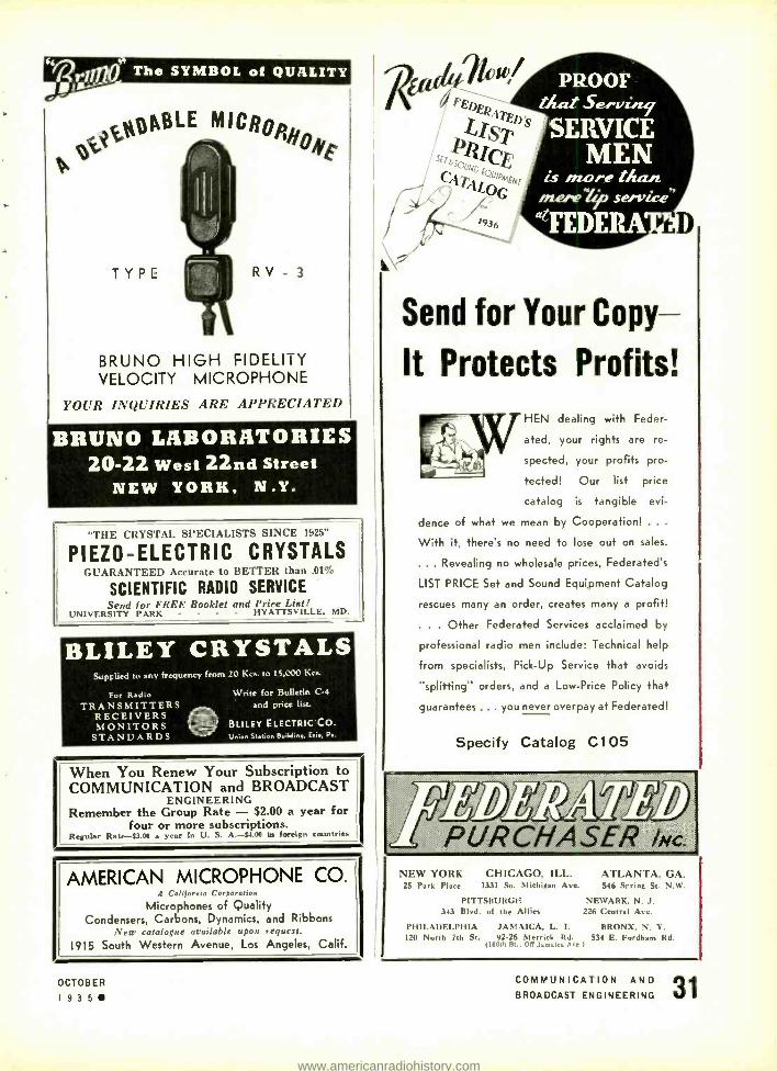
iNppBLE MI
to. °s '
HF
TYPE RV - 3
BRUNO HIGH FIDELITY VELOCITY MICROPHONE
I11I'R INQUIRIES ARE APPRECIATED
BRUNO LABORATORIES 20 -22 West 22nd Street
NEW YORK, N.Y.
THE CRYS'fAL SPECIALISTS SINCE 1925"
PIEZO- ELECTRIC CRYSTALS GUARANTEED Accurate to BETTER than .01%
SCIENTIFIC RADIO SERVICE Send for FREE Booklet and Price List!
UNIVERSITY PARK - - - - HYATTSVILLE. MD.
BLILEY CRYSTALS Supplied to any frequency from 20 Kcs. to 1:,000 Kcs.
For Radio TRANSMITTERS
RECEIVERS MONITORS
STANDARDS
Write for Bulletin C-4
and price list.
BLILEY ELECTRIC CO. Union Station Building, Erie, P..
When You Renew Your Subscription to COMMUNICATION and BROADCAST
ENGINEERING Remember the Group Rate - $2.00 a year for
four or more subscriptions. Regular Rate -$3.00 a year in U. S. A. -$4.011 in foreign countries
AMERICAN MICROPHONE CO. A Calilorroo Corporation
Microphones of Quality Condensers, Carbons, Dynamics, and Ribbons
New catalogue available upon request.
1915 South Western Avenue, Los Angeles, Calif.
OCTOBER
1 g35
Send for Your Copy-
It Protects Profits!
HEN dealing with Feder-
ated, your rights are re-
spected, your profits pro-
tected! Our list price
catalog is tangible evi-
dence of what we mean by Cooperation! .
With it, there's no need to lose out on sales.
... Revealing no wholesale prices, Federated's
LIST PRICE Set and Sound Equipment Catalog
rescues many an order, creates many a profit!
. . . Other Federated Services acclaimed by
professional radio men include: Technical help
from specialists, Pick -Up Service that avoids
"splitting" orders, and a Low -Price Policy that
guarantees ... you never overpay at Federated!
Specify Catalog C105
5
pl/R.CHA.SER INC.
NEW YORK CHICAGO, ILL. 25 Park Place 1331 So. Michigan Ave.
PITTSBURGH 343 Blvd. of the Allies
PHILADELPHIA JAMAICA, L. I. 120 North 7th St. 92.26 Merrick Rd.
ore .111,111, \,..
ATLANTA, GA. 546 Sprint St. N.W.
NEWARK, N. J. 226 Central Ave.
BRONX. N. Y. 534 E. Fordham Rd.
COMMUNICATION AND 31 BROADCAST ENGINEERING
www.americanradiohistory.com

¡J iti a CARDWELL tlzeréi moue better! RECEIVING CONDENSERS - - - - - VARIABLE AND FIXED
(AIR -DIELECTRIC) CONDENSERS FOR HIGH AND LOW POWERED TRANSMITTERS Contract -Manufacturing Service specialising in designing, or manufacturing to specifications, of Inductances. Transformers, Relaye, Automatic Telegraph equipment, eleetro- mechanical devices
and instruments and stamped and welded aluminum and duralumin products. The Allen D. Cardwell Manufacturing Corp. . . . 91 Prospect Street, Brooklyn, New York
THE STANDARD OF COMPARISON " UNIVERSAL
Professional Recording Machine Designed and built to insure Highest Class Results -Solid, heavy, dependable - Precision machined thruout: 16 in. dis-
tortion -proof turntable disc -Con its nt speed rim drive without "waver" or "wow " -110 volt A. C. 100% synchronous, reversible motor -Solid steel bar slide -Special Universal power cutter with four adjustments for damping -Engineered by Universal to provide the best in instantaneous recording equipment.
Write for detailed description. UNIVERSAL MICROPHONE CO., LTD.
424 Warren Lane Inglewood, Calif., U. S. A.
New METAL COVERED FUSE MOUNTING
built and ing meets
Designed and built for, use in metal tube equipped sets! Made for stand. ard 3AG fuses. Compact -21/4" x t /s" x a /' overall. Requires no mounting screw. Easy and quick to install, efficient. Comes without or with 1, 11/4, 2, or 3 amp. precision
d Underwriters' approved 3AG fuses. This mount - Underwriters' requirements. Priced right.
SAMPLE d manufacturers and set builders can get a sample of this
LITTELFUSE No. 1126 METAL COVERED FUSE MOUNTING. Write
LITTLELFUSE LABS. 4242 LINCOLN AVENUE. CHICAGO, ILL.
kin VIlit
FREQUENCY MEASURING SERVICE Many stations find this exact measuring service of great value for routine observation of transmitter perform- ance and for accurately calibrating their own monitors.
MEASUREMENTS WHEN YOU NEED THEM MOST
R. C. A. COMMUNICATIONS, Inc. Commercial Department
A RADIO CORPORATION OF AMERICA SUBSIDIARY 66 BROAD STREET NEW YORK, N. Y.
OBI TYPE 102 STATION FREQUENCY METER for POLICE RADIO STATIONS,
and fer any station inn In the 1,300 to 23,000 ke. range. A direct -reading. highly accurate means of checking transmitter fre- quency. In compliance with regulations of the Federal Communications Commission. Also -Type 101 Micrometer Frequency Meter, band - spread, heterodyne -type. a.e.operated instrument. Write for data.
QUALITY WORKMANSHIP PROVED PERFORMANCE
LAMPKIN LABORATORIES, FLOR DA ON,
Write for complete information.
SAJA SYNCHRONOUS RECORDING MOTORS HIGH TORQUE, VIBRATIONLESS, GEARLESS SINGLE and
DUAL SPEED, FAITHFUL REPRODUCTION NEEDLES -All Types for Cutting and Playback - Finest Quality Feeding
Mechanisms- Cutting Heads, etc., etc. NEXT MONTH -startling announcement of the new DURALOTONE DISC
for direct recording. EFFICIENT- DIFFERENT. SOUND APPARATUS CO., 150 West 46th Street, New York City
INDEX OF ADVERTISERS A
American Microphone Co 31 American Transformer Co 27 Amperite Corp. Second Cover Ansley Radio Corp. 6
B Bank's Inter -Air Prod. Co "9 Bl Co. 5 Bliley Elec. Co. 31 Kenyon Transformer Co., Inc lec Bruno Labs. 31 L
Federated Purchaser. Inc 31 G
General Radio Co. Third Cover II
Hamtnarlund Mfg. Co K
C Latnpkln Labs. Capitol Radio Eng. Institute 29 Llttelfuse Labs. Cardwell Mfg. Corp.. Allen D 32 P Cornell- Dubiller Corp. 6 Presto Recording Corp
s
R Radio Receptor Co.. Inc. 27 Radio Transceiver Labs 27 Radiotone Recording Co 29 RCA Communications, Inc..... 32 RCA Mfg. Co., Inc. Fourth Cover
s Scientific Radio Service 31
29 Sound Apparatus Co 32
U
32 United Transformer Co., Inc 3 32 Universal Microphone Co.. Ltd 32
W 1 Ward Leonard Elec. Co O
3 2
OCTOBER
I935 COMMUNICATION AND BROADCAST ENGINEERING
www.americanradiohistory.com

E 14 :11T ESSENTIALS F4 11t MEASURING It El'EIVEItS
One of the Laboratories of Philco Radio and Television, General Radio Equipped
IN today's competitive mar- ket, the radio receiver
manufacturer must know the electrical characteristics of his product.
Essential in the design, test and manufacture of any re- ceiver are these eight General Radio instruments.
There is a General Radio laboratory instrument for every radio measurement problem. Consult General Radio for the latest informa- tion on radio and electrical laboratory apparatus and ac- cessories.
CATALOG H -K2 A comprehensive 200 -page cata-
log describing all General Radio lab - oratory measuring apparatus and in- dispensable lab- oratory acces- sories and parts. Available free of charge to
engineers, scientists and technicians.
WRITE FOR YOUR COPY
A- Decade Resistance Box, Type 602 -J, I I , 110 ohms to- tal in I ohm steps $50.00
B- Beat -Frequency Oscillator, Type 613 -B, 10 to 11,500 cycles, direct reading $210.00
C- Bridge Amplifier, Type 514 -A, voltage amplification of 200 to 1, flat frequency characteristic between 50
cycles and 50 kc $85.00
D- Distortion -Factor Meter, Type 536 -A, for measure- ment of harmonic distortion to 0.02¡0, frequency range 380 -420 cycles $140.00
E- Standard -Signal Generator, Type 603 -A, 100 kc to 25,000 kc range, 400 cycle modulation, 0.5 my to I volt output continuously adjustable $600.00
F- Variac Transformer, Type 200 -CM, for adjusting line voltage, output continuously variable from 0 to 135
volts $17.50
G- Output Power Meter, Type 583 -A, 0.1 milliwatt to 5,000 milliwatts, direct reading 0 db to 17 db with 1 mw reference level $95.00
H- Reactance Meter, Type 421 -A, for rapid measurement and alignment of coils and condensers, capacitance range 0 to 500 Rif, frequency ranges 125 to 300 kc and 550 to 4.000 kc $445.00
General Radio Company Cambridge, Massachusetts
www.americanradiohistory.com

as
INDIVIDUAL as a
TAILORED GARMENT
BUT the tailor's problem is comparatively simple iv hen compared with the complicated problems that confront the studio engineer. Speeds
Input Equipment must be specially designed for the station's needs to he efficient. Whether it be KVSO, KSD, KNX, or WGN, there is an RCA solution for the problem.
Whether it be the control system for elaborate network productions or the simplified single channel arrangements for smaller stations, the same care and thought is given to the solution of the problem.
Only RCA can bring to you the vast wealth of experience gained in the solution of unnumbered Speech Input Equipment questions, and only RCA can bring to you the highly specialized technical skill which will result in the speedy and satisfactory termination of your difficulty.
Don't hesitate to send in your studio problems. A complete stock of standard panels, designed for extreme flexibility, may be assembled to quickly and accurately fill your individual requirements.
TRANSMITTER SECTION New York, 1270 Sixth Avenue Chicago, i l l No. Canal Street San Francisco, 170 Ninth Street Dallas, Santa Fe Building
Atlanta, 144 Walter Street, N. W.
RCA Manufacturing Co., Inc., Camden, N. J. A Subsidiary of the
RADIO CORPORATION OF AMERICA
www.americanradiohistory.com