engineering 1040: mechanisms & electric circuits fall 2011 introduction to embedded systems
TRANSCRIPT

Engineering 1040: Mechanisms & Electric Circuits
Fall 2011
Introduction to Embedded Systems

A Washing Machine

A Mechatronics System

Embedded Systems (1)
• An embedded system is a computer based system which is specifically designed to perform one or several dedicated functions in real-time.
• An embedded system comprises of a combination of computer hardware and software, perhaps additional parts, either mechanical or electronic that are designed to perform a dedicated task.
• Characteristics of embedded systems– Comprises the least required resources– designed to execute a specific task– often interfaced with sensors in order to get feedback of
process parameters– perform real time operations– designed to operate under harsh environments

Embedded Systems (2)• The central processing unit (CPU) of the embedded system is
the most important element of the system. • The CPU is usually a processor. • Components of a CPU
– Arithmetic logic unit (ALU) - performs arithmetic and logical operations
– Control unit (CU) – extracts instructions from memory and decodes and executes them, calling on the ALU when necessary..
• Embedded systems are used in mobile phones, mp3 players, video game consoles, digital cameras, DVD players & GPS receivers use such embedded systems etc.


Microcontroller Components (1)• CPU
– Ranging from small and simple 4-bit processors to complex 32- or 64-bit processors.
• In-circuit programming and debugging support.• Clock generator
– often an oscillator for a quartz timing crystal, resonator or RC circuit.• Random-access memory (RAM)
– Type of volatile memory for data storage.• Read-only memory (ROM),
– Erasable programmable read only memory (EPROM)– Electrically Erasable Programmable Read-Only Memory (EEPROM) – Flash memory for program and operating parameter storage.

Microcontroller Components (2)
• Discrete input and output bits, allowing control or detection of the logic state of an individual package pin.
• Serial input/output such as serial ports (UARTs). – I²C, – Serial Peripheral Interface (SPI) – Controller Area Network (CAN) for system interconnect
• Peripherals such as timers, event counters.• Pulse width modulation (PWM) generators.• Analog-to-digital converters and digital-to-analog converters.
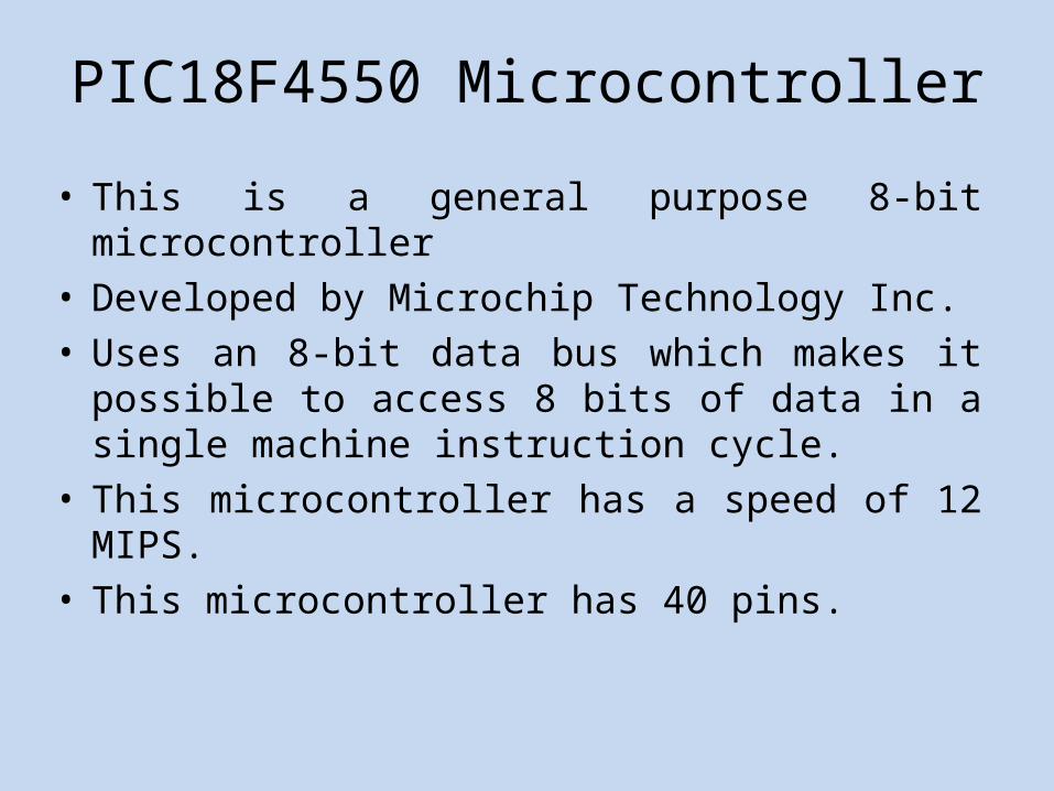
PIC18F4550 Microcontroller
• This is a general purpose 8-bit microcontroller• Developed by Microchip Technology Inc. • Uses an 8-bit data bus which makes it possible to
access 8 bits of data in a single machine instruction cycle.
• This microcontroller has a speed of 12 MIPS.• This microcontroller has 40 pins.

PIC18F4550 Microcontroller
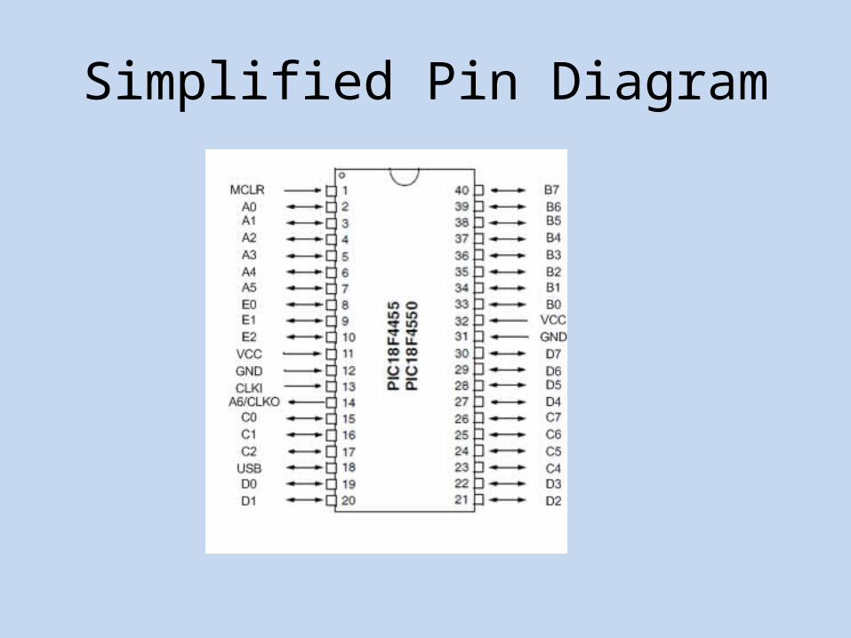
Simplified Pin Diagram
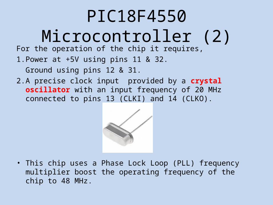
PIC18F4550 Microcontroller (2)For the operation of the chip it requires,1. Power at +5V using pins 11 & 32.
Ground using pins 12 & 31. 2. A precise clock input provided by a crystal oscillator with an input
frequency of 20 MHz connected to pins 13 (CLKI) and 14 (CLKO).
• This chip uses a Phase Lock Loop (PLL) frequency multiplier boost the operating frequency of the chip to 48 MHz.

Applications of the PIC18F4550 microcontroller
• Sending and receiving digital signals using the digital I/O ports• Measuring analog voltages from +0V – +5V.• Sending PWM signals for driving dc motors

Pins used for sending & receiving digital signals

Pins used for receiving digital signals

Measuring analog voltages using the PIC18F4550 microcontroller
• There are 5 analog input pins.• Marked pins can measure analog
voltages between +0 V & +5 V.• Analog voltages are measured
by using analog to digital converters (ADC).
• The ADC has a resolution of 10-bits.i.e.:analog +0 V -> digital 0analog +5 V -> digital 1023

Generating PWM signals for driving DC motors
• The pin 16 (C1) could be used to send PWM signals for driving DC motors.
• It has a digital resolution of 10-bits (0-1023 in decimal).
• The frequency of the PWM signal is 2.44 kHz.

Microcontroller development tools: Hardware
PORT B PORT D PORT C
VCC
GND
PORT A PORT E
PIC 18F4550 USB
POWER JACKLCD
BLUE TOOTHPUSH BUTTONS

Microcontroller development tools: Software
• IDE (Integrated Development Environment): A software application that facilitates all aspects developing of embedded software.– Source code editor.– A compiler.– A debugger.
• Software interface for loading the compiled code into the microcontroller.