engineer spec of lk-be-au17 auo panel m170eg01 vd kioskline · auo panel m170eg01 vd kioskline ......
TRANSCRIPT

Page 1 of 18
Engineer Spec of LK-BE-AU17
AUO Panel M170EG01 VD
KioskLine
Optionally available w/ touch screen
(CL1781AT)
Date : 2009/24/07
Version: 1.00
Prepare by :
Check by :
Page 2 of 18
REVISION HISTORY
Version Date Page Section Description
1.0 2009/24/07 ALL ALL New Release
Page 3 of 18
Table of Contents
1. General ..............................................................................................................5
1.1 Product description .......................................................................................5
1.2 Preset Timing...............................................................................................5
2. Features ............................................................................................................6
2.1 LCD panel....................................................................................................6
2.2 Power supply ...............................................................................................6
2.3 A/D board....................................................................................................6
2.3.1 General Description .............................................................................7
2.3.2 Signal Input .......................................................................................7
2.3.3 Silkscreen Top ....................................................................................8
2.3.4 VGA Signal Input ................................................................................8
2.3.5 CN2...................................................................................................8
2.3.6 CN6...................................................................................................9
2.3.7 CN8...................................................................................................9
2.3.8 CN10...............................................................................................10
2.3.9 Major Component List........................................................................10
2.4 Inverter.....................................................................................................11
2.4.1 Electrical performance .......................................................................11
2.4.2 CN1.................................................................................................12
2.4.3 CN2,CN3, CN4, CN5 ........................................................................ 152
2.4.4 Inverter test ................................................................................... 152
2.4.5 Major Component List...................................................................... 153
2.5 Touch panel ............................................................................................. 114
2.5.1 Features ........................................................................................ 114
2.5.2 General specification ....................................................................... 124
2.5.3 Optical characteristics...................................................................... 154
2.5.4 Electrical characteristics................................................................... 154
2.6 Touch controller........................................................................................ 115
2.6.1 Hardware specifications ................................................................... 115
2.6.2 Software spedifications .................................................................... 115
3.0 Electrical characteristics and performance .................................................. 166
3.1 White balance Adjustment...........................................................................166

Page 4 of 18
3.2 Brightness uniformity................................................................................ 166
3.3 Contrast Ratio .......................................................................................... 176
4.0 OSD Menu .................................................................................................... 187
5.0 Environmental conditions ............................................................................ 188
6.0 Drawing ....................................................................................................... 188

Page 5 of 18
1. General
1.1 Product description
This open frame is designed by Richardson / Canvys. It will use AUO M170EG01 VD Panel,
supported resolution up to1280*1024. This specification only supports CL1781, based features
as below:
Use RTD2545 Scaler Chipset, RTD2120L MCU
Navive resolution 1280*1024
Input connector: VGA & DVI
Product code:
L K – B E – A U 17 O N D W
A U = Panel maufacturer
17 = Panel size
O = Open Frame
N = Non integration (K = cap touch, R = res touch)
D = DC input
W = Input (VGA & DVI)
Further options: sealing rubber in front (only on req.)
1.2 Preset Timing
Signal
Polarity Frequency
Timing Dot Clock
MHz H V FH (kHz) FV (Hz)
VGA 640×480 25.2 - - 31.5 60.0
VESA 800×600 40.0 + + 37.9 60.3
VESA 720x400 35.5 + + 37.9 85.0
VESA 1024×768 65.0 - - 48.3 60.0
VESA 1280x1024 108.0 + + 64.0 60.0
Page 6 of 18
2. Features
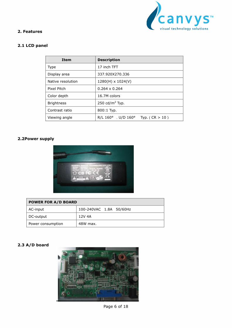
2.1 LCD panel
Item Description
Type 17 inch TFT
Display area 337.920X270.336
Native resolution 1280(H) x 1024(V)
Pixel Pitch 0.264 x 0.264
Color depth 16.7M colors
Brightness 250 cd/m2 Typ.
Contrast ratio 800:1 Typ.
Viewing angle R/L 160° ,U/D 160° Typ.(CR > 10)
2.2Power supply
POWER FOR A/D BOARD
AC-input 100-240VAC 1.8A 50/60Hz
DC-output 12V 4A
Power consumption 48W max.
2.3 A/D board
Page 7 of 18
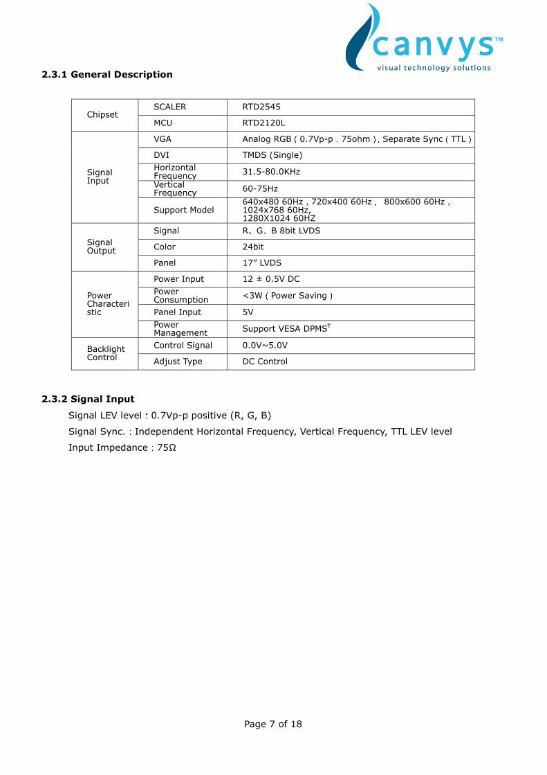
2.3.1 General Description
SCALER RTD2545 Chipset
MCU RTD2120L
VGA Analog RGB(0.7Vp-p,75ohm),Separate Sync(TTL) DVI TMDS (Single)
Horizontal Frequency
31.5-80.0KHz
Vertical Frequency
60-75Hz
Signal Input
Support Model 640x480 60Hz,720x400 60Hz, 800x600 60Hz,1024x768 60Hz, 1280X1024 60HZ
Signal R、G、B 8bit LVDS
Color 24bit Signal Output
Panel 17” LVDS
Power Input 12 ± 0.5V DC
Power Consumption
<3W(Power Saving)
Panel Input 5V
Power Characteristic
Power Management
Support VESA DPMST
Control Signal 0.0V~5.0V Backlight Control
Adjust Type DC Control
2.3.2 Signal Input
Signal LEV level:0.7Vp-p positive (R, G, B)
Signal Sync.:Independent Horizontal Frequency, Vertical Frequency, TTL LEV level
Input Impedance:75Ω
Page 8 of 18
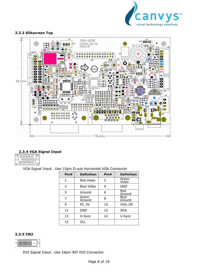
2.3.3 Silkscreen Top
2.3.4 VGA Signal Input
VGA Signal Input,Use 15pin D-sub horizontal VGA Connector
Pin# Definition Pin# Definition
1 Red Video 2 Green Video
3 Blue Video 4 GND
5 Ground 6 Red Ground
7 Green Ground
8 Blue Ground
9 PC_5V 10 VGA_DE
11 GND 12 SDA
13 H-Sync 14 V-Sync
15 SCL
2.3.5 CN2
DVI Signal Input,Use 24pin 90º DVI Connector
Page 9 of 18
Pin# Definition Pin# Definition Pin# Definition
1 T.M.D.S Data2- 9 T.M.D.S Data1- 17 T.M.D.S Data0-
2 T.M.D.S Data2+ 10 T.M.D.S Data1+ 18 T.M.D.S Data0+
3 T.M.D.S Data2/4 Shield
11 T.M.D.S Data1/3 Shield
19 T.M.D.S Data0/5 Shield
4 NC 12 NC 20 NC
5 NC 13 NC 21 NC
6 DDC-Serial Clock(SCL)
14 +5V Power 22 T.M.D.S Clock Shield
7 DDC-Serial Data(SDA)
15 NC 23 T.M.D.S Clock+
8 NC 16 HPD 24 T.M.D.S Clock-
2.3.6 CN6
INVERTER Interface,Connect INVERTER and A/D Board,Connect Type:PH2.0-9Pin 90ºJACK
Pin# Definition Description
1 5V NC (Internal 5V Power Input)
2 5V NC (Internal 5V Power Input)
3 GND Ground
4 12V INVERTER 12V Power Supply
5 12V INVERTER 12V Power Supply
6 ON/OFF Inverter On/Off Switch
7 PWM Brightness Adjustment
8 GND Ground
9 GND Ground
2.3.7 CN8
Keyboard Interface,connect OSD adjustment and A/D Board
Connect Type:PH2.0-8 Pin 90ºJACK
Pin# Definition Description
1 LEDG Green LED Indicator
2 GND Ground
3 LEDR Red LED Indicator
4 MENU OSD Menu Keyboard
5 LEFT Left Keyboard
6 RIGHT Right Keyboard
7 AUTO Exit/ Auto Adjust
8 ON/OFF Power On/Off keyboard
Page 10 of 18
2.3.8 CN10
LVDS Input interface,Connect PANEL,Connector Type:2.0mm Spacing ,90ºdouble row ,30Pin
1 VCC Panel 5V Power Input 2 VCC Panel 5V Power Input
3 VCC Panel 5V Power Input 4 GND Ground
5 GND Ground 6 GND Ground
7 RXE3- LVDS EVEN 3- Signal 8 RXE3+ LVDS EVEN 3+ Signal
9 RXEC- LVDS Clock - Signal 10 RXEC+ LVDS Clock + Signal
11 RXE2- LVDS EVEN 2- Signal 12 RXE2+ LVDS EVEN 2 + Signal
13 RXE1- LVDS EVEN 1- Signal 14 RXE1+ LVDS EVEN 1+ Signal
15 GND Ground 16 GND Ground
17 RXE0- LVDS EVEN 0- Signal 18 RXE0+ LVDS EVEN 0+ Signal
19 RXO3- LVDS Signal of Odd Channel 3-
20 RXO3+ LVDS Signal of Odd Channel 3+
21 RXOC- LVDS Signal of Odd Channel Clock-
22 RXOC+ LVDS Signal of Odd Channel Clock+
23 GND Ground 24 GND Ground
25 RXO2- LVDS Signal of Odd Channel 2-
26 RXO2+ LVDS Signal of Odd Channel 2+
27 RXO1- LVDS Signal of Odd Channel 1-
28 RXO1+ LVDS Signal of Odd Channel 1+
29 RXO0- LVDS Signal of Odd Channel 0-
30 RXO0+ LVDS Signal of Odd Channel 0+
2.3.9 Major Component List
NO Item Name Spec./Standard
1 U1 Converter ACT4060
2 U2 Regulator AIC1084-33PM
3 U4 SCALER RTD2545
4 U6 MCU RTD2120L
5 F1 FUSE 20S-070L 7A
6 CN10 30PINJack 30PIN 2.0mm
7 CN1 VGA Jack 15PIN (1-1734530-1)
8 CN2 DVIL Jack AMP1734148(DVI-I)
9 Y1 Crystal 24MHz
10 L5 Inductance 33uH
Page 11 of 18
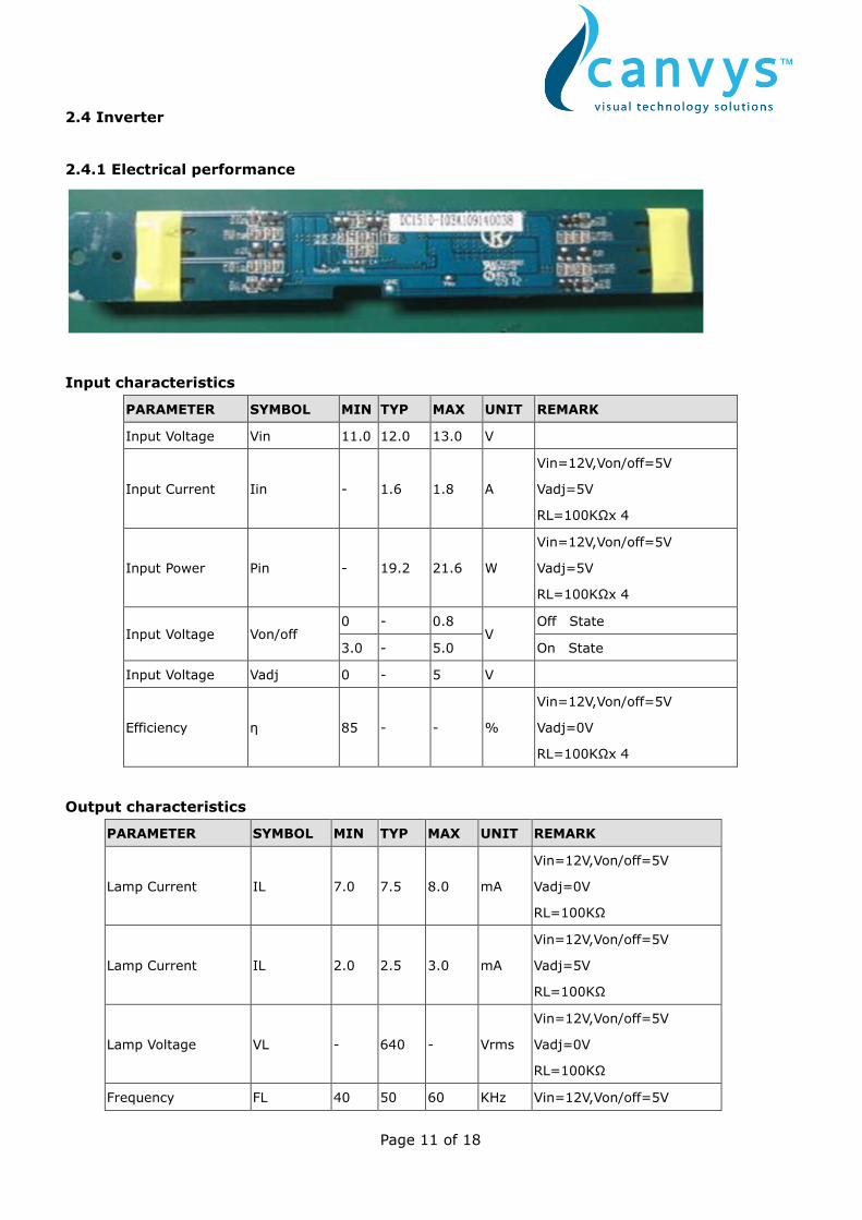
2.4 Inverter
2.4.1 Electrical performance
Input characteristics
PARAMETER SYMBOL MIN TYP MAX UNIT REMARK
Input Voltage Vin 11.0 12.0 13.0 V
Input Current Iin - 1.6 1.8 A
Vin=12V,Von/off=5V
Vadj=5V
RL=100KΩx 4
Input Power Pin - 19.2 21.6 W
Vin=12V,Von/off=5V
Vadj=5V
RL=100KΩx 4
0 - 0.8 Off State Input Voltage Von/off
3.0 - 5.0 V
On State
Input Voltage Vadj 0 - 5 V
Efficiency η 85 - - %
Vin=12V,Von/off=5V
Vadj=0V
RL=100KΩx 4
Output characteristics
PARAMETER SYMBOL MIN TYP MAX UNIT REMARK
Lamp Current IL 7.0 7.5 8.0 mA
Vin=12V,Von/off=5V
Vadj=0V
RL=100KΩ
Lamp Current IL 2.0 2.5 3.0 mA
Vin=12V,Von/off=5V
Vadj=5V
RL=100KΩ
Lamp Voltage VL - 640 - Vrms
Vin=12V,Von/off=5V
Vadj=0V
RL=100KΩ
Frequency FL 40 50 60 KHz Vin=12V,Von/off=5V
Page 12 of 18
Vadj=0V
RL=100KΩ
Output Open Voltage VL - 1450 - Vrms
Vin=12V,Von/off=5V
Vadj=0V
RL=∞KΩ
Output Open VL LATCH Vin=12V,Von/off=5V
RL=∞KΩ
Output Short VL LATCH Vin=12V,Von/off=5V
OUTPUT SHORT TO GND
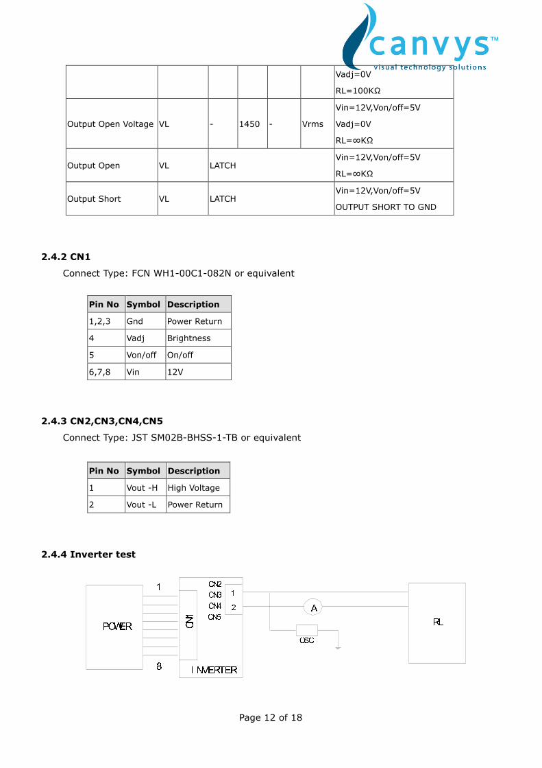
2.4.2 CN1
Connect Type: FCN WH1-00C1-082N or equivalent
2.4.3 CN2,CN3,CN4,CN5
Connect Type: JST SM02B-BHSS-1-TB or equivalent
Pin No Symbol Description
1 Vout -H High Voltage
2 Vout -L Power Return
2.4.4 Inverter test
Pin No Symbol Description
1,2,3 Gnd Power Return
4 Vadj Brightness
5 Von/off On/off
6,7,8 Vin 12V
OSCAI NVERTER12CN2CN3CN4CN5POWER RLCN11
8

Page 13 of 18
2.4.5 Major Component List
NO Item Name Spec./Standard NO
1 CN1 Connector WH1-000C0-082N ,1A/125V UL(E2042211)
S1206-4,4A/31V UL(E245449) 2 F1 FUSE
466series, 4A/32V UL(E10480)
3 CN2,3,4,5
Connector W01-01200-022N,1A/650V UL(E204211)
4 T1-T4 Transformer HTR002000N(EFD-11.7H) UL
Page 14 of 18
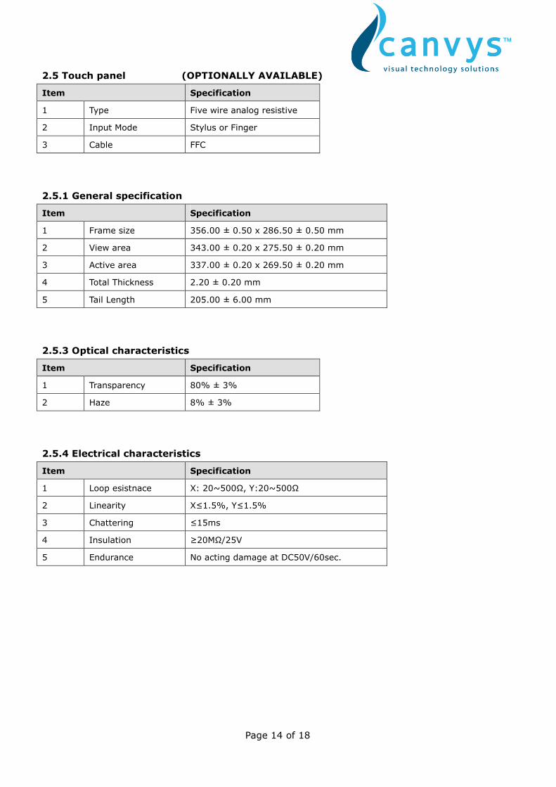
2.5 Touch panel (OPTIONALLY AVAILABLE)
Item Specification
1 Type Five wire analog resistive
2 Input Mode Stylus or Finger
3 Cable FFC
2.5.1 General specification
Item Specification
1 Frame size 356.00 ± 0.50 x 286.50 ± 0.50 mm
2 View area 343.00 ± 0.20 x 275.50 ± 0.20 mm
3 Active area 337.00 ± 0.20 x 269.50 ± 0.20 mm
4 Total Thickness 2.20 ± 0.20 mm
5 Tail Length 205.00 ± 6.00 mm
2.5.3 Optical characteristics
Item Specification
1 Transparency 80% ± 3%
2 Haze 8% ± 3%
2.5.4 Electrical characteristics
Item Specification
1 Loop esistnace X: 20~500Ω, Y:20~500Ω
2 Linearity X≤1.5%, Y≤1.5%
3 Chattering ≤15ms
4 Insulation ≥20MΩ/25V
5 Endurance No acting damage at DC50V/60sec.

Page 15 of 18
2.6 Touch controller
The touchscreen controller provides the optimistic performance for 5-wire analog resistive touch
panels. It communicates with PC system directly through USB port .The touchscreen device
driver emulates mouse left and right button.
2.6.1 Hardware specifications
Circuit Board Dimension 68.00 mm x 21.00 mm
Power Requirement +5VDC (Max. 150mA, typical current depend on specified panel,
50mV to peak max. ripple)
Operating Temperature 0 to 60 °C
Storage Temperature -40 to 80 °C
Relative Humidity 95% at 60 °C
Protocal COM: 9600 BPS baudrate, 1 Start bit, 8 Data bits, None parity,
1 Stop bit
USB: USB1.1 full speed (HID 1.11)
Report Rate COM: Minimum 63 PPS ( Point per Second)
USB: Minimum 86 PPS (Point per Second)
Response Time Max. 20 ms
Pin Out Definition RT, RL, SB, LT, LL
Panel Requirements Capacitive 80nF (max.) Resistance 30 to 500 Ohm
(pin to pin on drive layer)
2.6.2 Software specifications
The touchscreen device driver supports operation systems, including Windows 2000, Windows
XP, Windows XP embedded, Windows Vista. 14.
Page 16 of 18
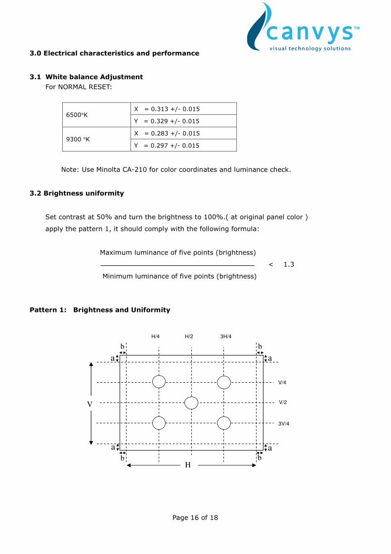
3.0 Electrical characteristics and performance
3.1 White balance Adjustment
For NORMAL RESET:
X = 0.313 +/- 0.015 6500°K
Y = 0.329 +/- 0.015
X = 0.283 +/- 0.015 9300 °K
Y = 0.297 +/- 0.015
Note: Use Minolta CA-210 for color coordinates and luminance check.
3.2 Brightness uniformity
Set contrast at 50% and turn the brightness to 100%.( at original panel color )
apply the pattern 1, it should comply with the following formula:
Maximum luminance of five points (brightness)
< 1.3
Minimum luminance of five points (brightness)
Pattern 1: Brightness and Uniformity
H/2 3H/4
V/4
V/2
3V/4
H/4
H
V
a
b
a
b
a
b
a
b

Page 17 of 18
3.3 Contrast Ratio
Apply a 1280 x 1024@60Hz signal with white pattern, Set contrast at 50% and turn the
brightness to 100% , measure luminance at full white (Lw) and full black ( Lb ) should be comply
with (CR = Lw / Lb)
CR: 800 : 1 typ
4.0 OSD Menu
Main Menu Sub Menu Reference
Contrast Set Screen Contrast
Brightness Set backlight Brightness
Color Setting
Color Temp
Select color temperature 9300º K, 6500º K
and User color, and set user color
temperature
Auto Adjust
H-position
V-position
Clock
Image Setting
Phase
Gamma 1
Gamma 2
Gamma 3
Gamma 4
LUT Setting
Gamma 5
Select display GAMMA
OSD H-pos. Set horizontal position of OSD Menu
OSD V-pos. Set vertical position of OSD Menu OSD Setting
OSD Timer Set display time of OSD Menu

Page 18 of 18
Signal Source Select input signal
Sharpness Set picture sharpness Others
RESET
5.0 Environmental conditions
Operation
Temperature 0°C ~ 40°C
Humidity 20 to 70%
Air pressure 795-1013 mbar
Storage
Temperature -20°C to 60°C
Humidity 5- 95% (non –condensing )
Air pressure 300-1013 mbar
Transport
Temperature -20°C to 65°C
Humidity 5- 95% (non –condensing )
Air pressure 300-1013 mbar
6.0 Drawing (see separate file)
Physical specifications
Weight: 6.0 kg
Standard mounting: VESA compatible (100 mm spacing)
Vendor:
Europe: Headquarter (North America):
Canvys Richardson Electronics Ltd.
A Division of Richardson Electronics GmbH 40W267 Keslinger Road
Raiffeisenstraße 5 PO Box 393
D-78166 Donaueschingen LaFox, IL 60147-0393, USA
Internet: www.canvys.com
Tel.: +49 (0) 771 83 00 – 0
Fax.: +49 (0) 771 83 00 – 80
VAT-No.: DE128240232
WEE-Reg.-Nr.: DE64678500