engine control system - c-141 heavenc141heaven.info/dotcom/training_materials/section_02_06.pdf ·...
TRANSCRIPT

ENGINE CONTROL SYSTEM
The two basic ranges of operation of the engine control system are the flight range and thiust reverse range. Inadvertent movement of the throttle control lever from flight range to thrust reverse range is prevented by a cam i,ncorporated in the throttle quadrant. The throttle must be retarded to idle position and then raised approximately 1 1/8 inches and pulled aft into the thrust reverse range. Control by the throttle over the thrust reverser system is provided by a mechanical linkage to the thrust reverser control valve. A thrust reverser mechanical lock-out pr events the application of engine power, when reverse thrust is selected, until the thrust reverser doors have been extended. A reverse thrust limiter, incorporated in the thrGttle quadrant, limits the engine power to the equivalent of 18,000 pounds of gross thrust so that the pilot does not have to monitor EPR and adjust throttles. Range of throttle travel from full reverse (zero degrees) to max.lmum flight power is 80 degrees. A friction adjustment knob is provided on the throttle quadrant. Engine fuel shutoff is provided by a separate system, the fuel shutoff actuator, and a cable actuated fuel supply shutoff valve. The engine control system consists of the following:
o Throttle Control Quadrant
o Engine Control Cables
o Cable Tension Regulator
o Engine Control Linkage
o Fuel Shutoff Actuator
o Thrust Reverser Control Linkage
o Automatic Throttle System (aircraft equipped with AWLS)
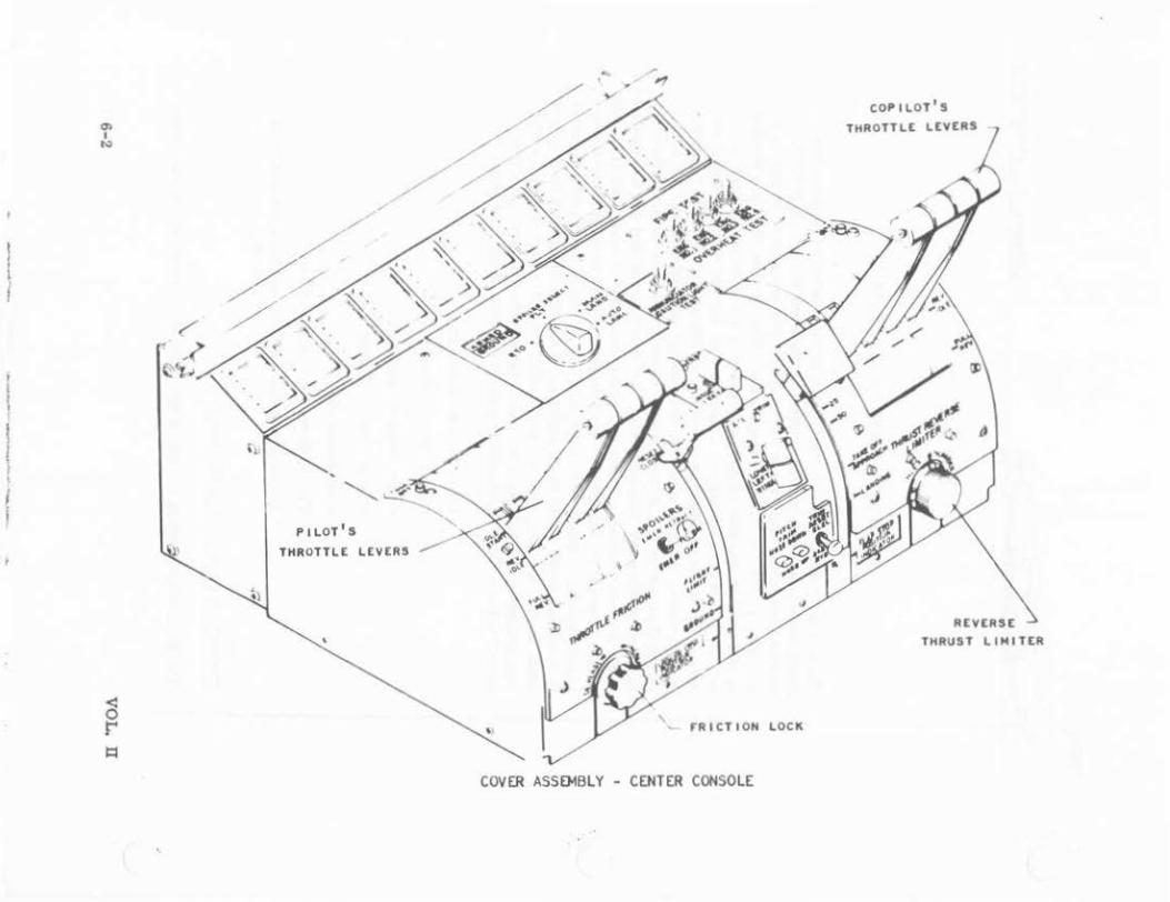
THROTTLE CONTROL QUADRANT.
The throttle quadrant is located on the flight station center console. This
VOL. n 6-1
l i
l t I I
"' I .,
'
PILOT'S
THROTTLE 'E ~ VERS ...........
'
COVER ASSOolBLY
' rRICTIOH LOCK
- CENTER CONSOLE
COPILOT'S
THROTTLE LEVERS
REVERSE THRUS T LIMITER
"' I ...
TUT
• rA IL SAr£ T£5
AND
ANNUNCIATOR AND CAUTION LIGH T
TUT rANH
[NIIAQ£ AND DIJ[NQAQ[ SWITCH
•
COr iLOT ATS tNQAQt
AND D I UNIIAQ[
ATS SPEED TRIH THUH8 WHEEL
rRICT ION LOC K
AUTOMATIC THROTTLE SYST EM CONTROLS
'
assembly is a du:ll unit providing two sets o{ throttle levers: one set for the copilot and one set for the pilot. The pilot's and copilot's throttle levers are interconnected by torque tubes. J..inkage from the torque tube connects to the cable drum for cable system control t~he engine Hnkage.
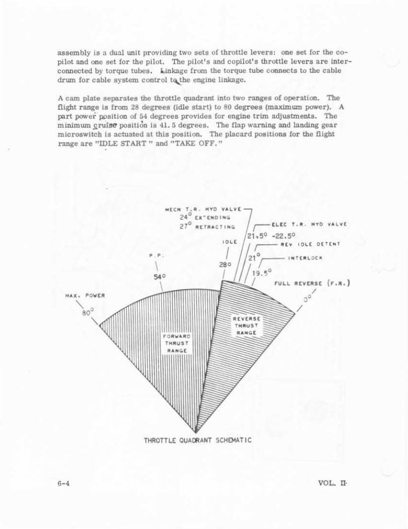
A cam plate separates the throttle quadrant into two ranges of operation. The flight range Is from 28 degrees (idle start) to 80 degrees (maximum power). A part power position of 54 degrees provides {or engine trim adjustments. The minimum sruise position Is 41. 5 degrees. The flap warning and landing gear microswltch is actuated at this position. The placard positions for the flight range are "IDLE START" and "TAKE OFF."
6-4
P , P .
\
M£CH T.R . HYO YAL¥( 24° (X"[NOINC:
0 27 R(TR ACTINC:
540
0 ~,....--- I N f Ul\. 0 C It
9.5°
roRv4 RD TNIIUST
AANC(
THROTTLE QUA~ANT SCHEMATIC
VOL. 0 ·
The reverse thrust range is (rom zero degrees to 28 degrees. The placard positions are "FULL REV'' (zero degrees) and "REV IDLE" (21 degrees). The mechanical thrust reverse hydraulic cootrol valve is actuated at 24 degrees for extending the thrust reverser doors as the throttle is moved toward the "FULL REV'' position and actuated at 27 degrees for retraction of the thrust reverse doors as the throttle is moved forward toward the flight range. Tho electrical control for the thrust reverser control valve is actuated at 21. 2 degrees to 22. 2 degrees through the thrust reverser pressurization switch. A thrust reverser Interlock system is actuated at 19. 5 degrees. A thrust reverser mechanical lockout prevents the reverser thrust application until the doors are fully extended.
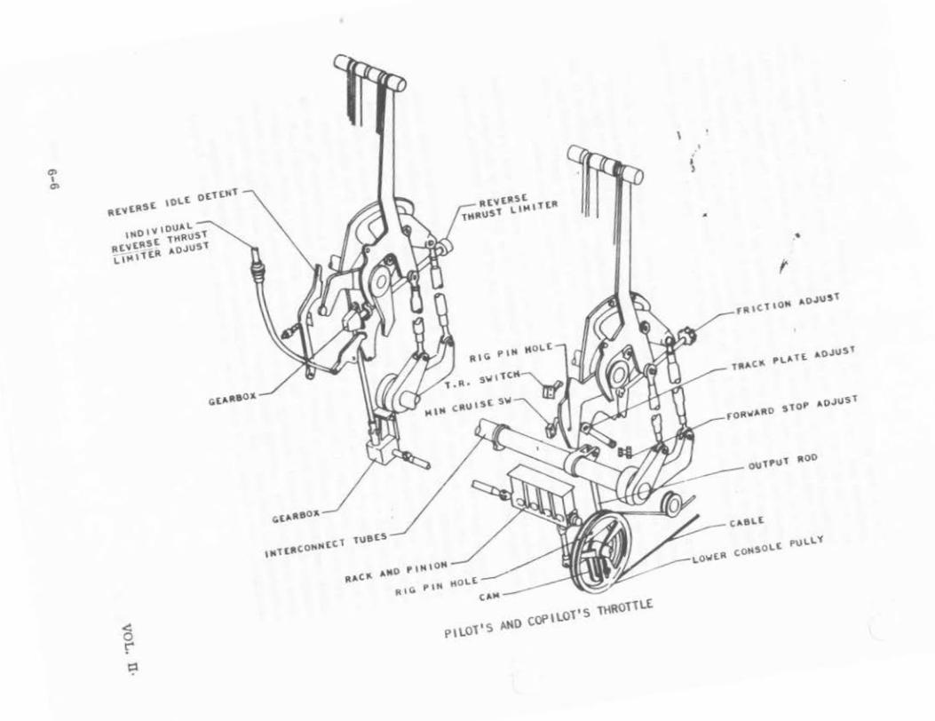
Two puahrods are connected to each throttle lever. One pushrod is t.he throttle lever power interco~ctlog rod to the torque tube crank. This rod transmits power requirements through the torque tube and connecting linkage to the cable drum and the cable system to the fuel control linkage. The second pushrod is the throttle lever lift interconnecting rod! that connects to a crank that rotates an lntershaft through the torque tube. Thls system provides for the lift movement of 1 1/8-inch of the throttle at both the pilot's and copilot's quadrants.
A friction adjustment knob, located below the pilot's throttle levers, IS provided for desired friction adjustments for all throttles. The friction in the copilot's throttles is obtained from the friction adjustment of the pilot's throttles through the lnterconnectlug torque tubes.
A thrust reverser limiter Is lDcorporated in the thro:tle quadrant to limit thrust so that the pilot does not bD.ve to mooitor EPR and adJust his throttles accordingly. An adjustable index thrust limiter control knob is located below the copilot's throttle lever. This adjustment is performed by the flight crew. To adjust the limiter, a special cbD.rt is consulted and the selected setting is based on the ambient temperature and barc.netric pressure on the runway. This adjustment limits the full reverse thrust of all four engines simultaneously. The system consists of the adjustment knob, an indicator assembly, a gear assembly rotating a horizontal torque shaft, an upper 90-degree gearbox, a vertical torque shaft, a lower 90-degree gearbox, a lower horizontal torque shaft, and a rack and pinion which operates a cam plate on the throttle cable drum assembly. This adjustment changes the mechanical advantage between the throttle lever and the fuel control lever throughout the operating environment of the aircraft. Provisions are incorporated for each individual engine to cc.npensate for differences In engine variations. The adjustment Is made at periodic intervals on the ground. Ground
VOL. D 6-5
C1> I
C1>
1140 IV tOU~L Rtvt~t5E tHRUSt L tH It tit ~oJUST
ltt~tllSE tH!tUSl UHI t t"
""c" ,.,.o "'"oil f'IG PIM HOLE
c ,. .. - --------\\
\
I )
•
f

adjustments provide for the accomplishment of adjusting aH four engines simultaneously by the reverse thrust lim iter adjusting knob by the aircrew. The individual thrust reverser limiter of each engine consists of a adjustment screw, a flexible shaft, and a master stop lever. These adjustments are located forward of the copilot's throttles. Rig .pin boles are provided ui the pilot's throttle lever carrier and the throttle lever track. An inclinometer and throttle bracket assembly are used to establish the throttle lever position.
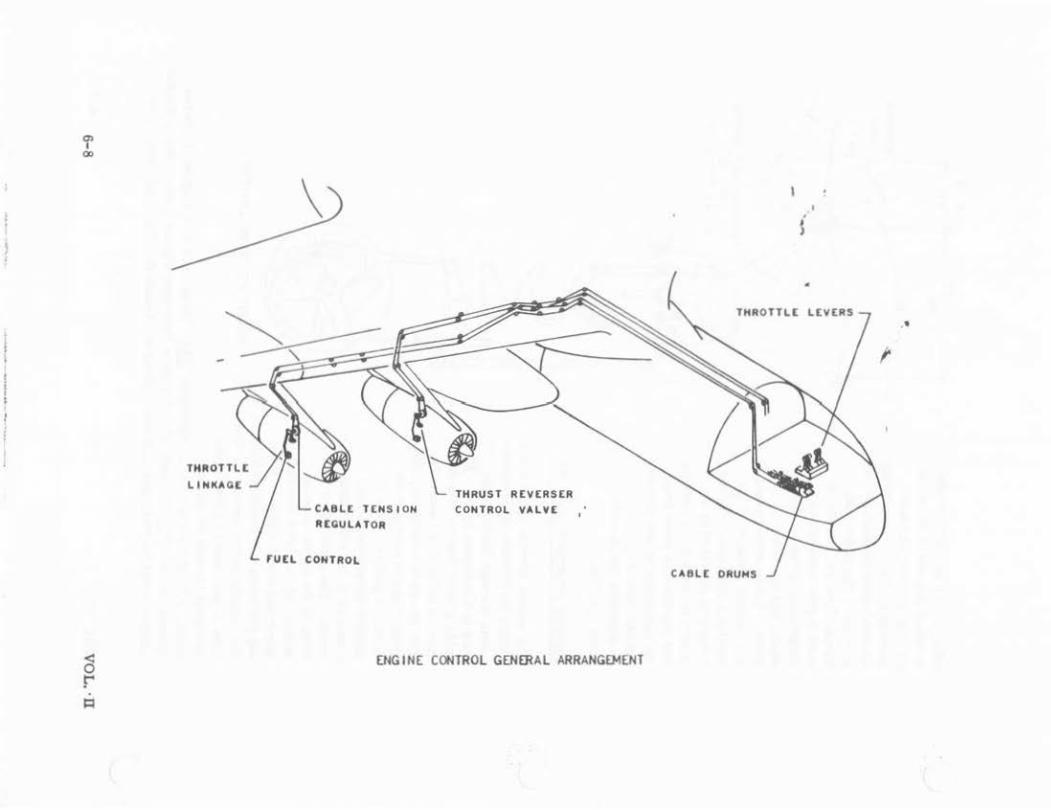
ENGINE CONTROL CABLES.
The engine throttle cable system transmits throttle lever movements through the fuselage and wing to the engine pylon. The cable system begins with the throttle cable drum and ends with the cable tension regulator located on the engine pylon strut. A pushrod from the throttle torque tube crank connects to the cable drum crank. The cable drum consists of the lower console pulley and cam with connecting upper and lower cables. Rig-ing pin boles are provided through
• • \
10.27
f AtVtASt
rOAWAAD JOLt DETENT LJrT W.T£
STAAT POSITION
the c0118ole pulley and cam. The THRUST REVERSER LIMITER cam is positioned by the thrust reverser limiter adjustment knob. All cables are coded. Example: ~ Throttle, No. 1 Engine, Increase Thrust Cable. TIB Throttle, No. 1 Engine Decrease Thrust Cable. No. 2 Engine Cables would be T2A, and T2B etc. These 3/16-incb flexible steel cables are
VOL. n 6-7
----- --
0> I
00
LINKAGE
CA8Lt TENS I OH IUGUlATOR
run CONTROL
THRUST REVERSER CONTROL VALVE
ENGINE CONTROL GENERAL ARRANGEMENT
THROTTLE LEVERS .. t
CABLE DRUMS
(
'
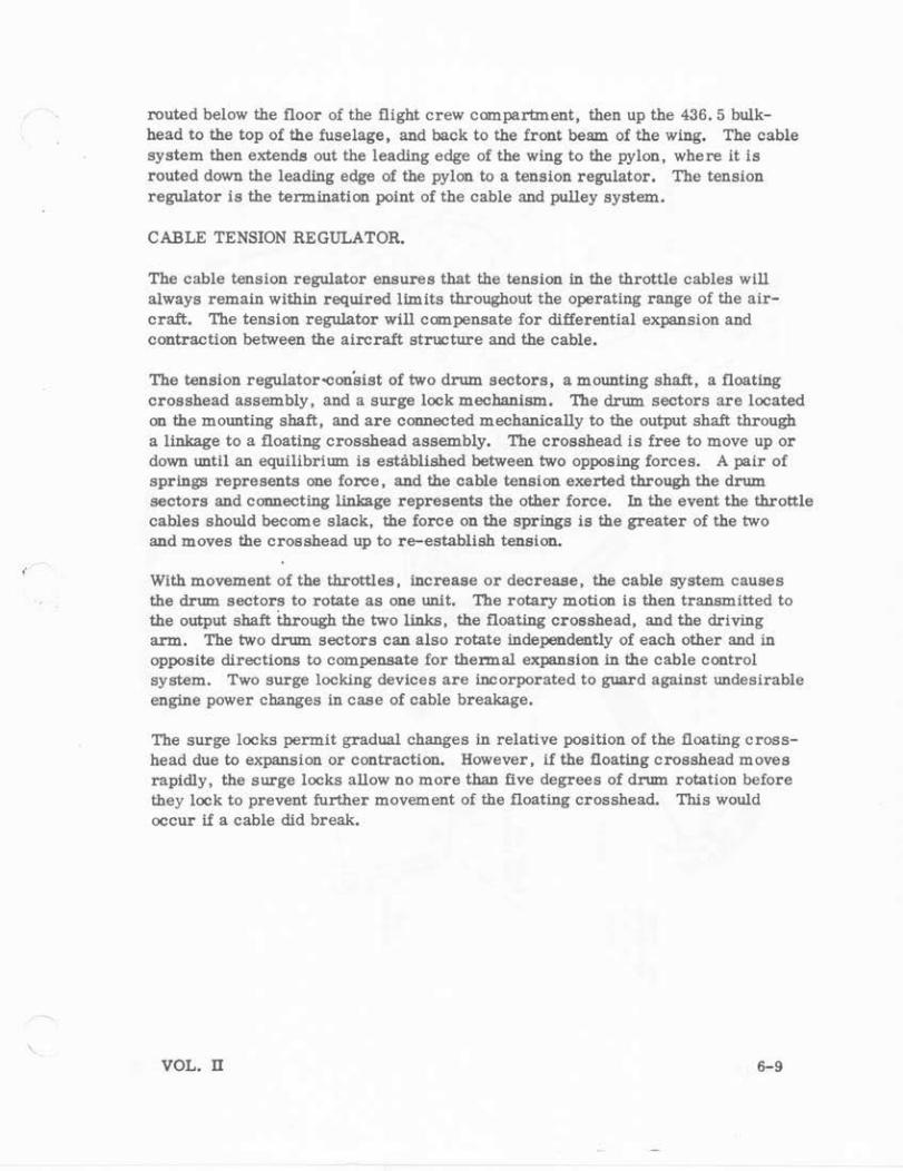
routed below the floor of the flight crew compartment, then up the 436. 5 bulkhead to the top of the fuselage, and back to the front beam of the wing. The cable system then extends out the leading edge of the wing to the pylon, where it is routed down the leading edge of the pylon to a tension regulator. The tension regulator is the termination point of the cable and pulley system.
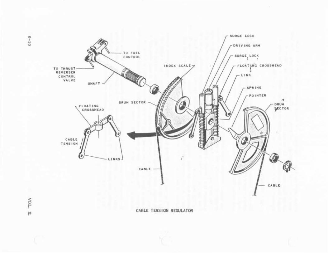
CABLE TENSION REGULATOR.
The cable tension regulator ensures that the tension in the throttle cables will always remain within required limits throughout the operating range of the aircraft. The tension regulator will compensate for differential expansion and contraction between the aircraft structure and the cable.
The tension regulator 'Consist of two drum sectors, a mounting shaft, a floating crosshead assembly, and a surge lock mechanism. The drum sectors are located on the mounting shaft, and are connected mechanically to the output shaft through a linkage to a floating crosshead assembly. The crosshead is free to move up or down until an equilibrium is established between two opposing forces. A pair of springs represents one force, and the cable tension exerted through the drum sectors and connecting linkage represents the other force. In the event the throttle cables should become slack, the force on the springs is the greater of the two and moves the crosshead up to re-establish tension.
With movement of the throttles, increase or decrease, the cable system causes the drum sectors to rotate as one unit. The rotary motion is then transmitted to the output shaft through the two links, the floating crosshead, and the driving arm. The two drum sectors can also rotate independently of each other and in opposite directions to compensate for thermal eXPaDsion in the cable control system. Two surge locking devices are incorporated to guard against undesirable engine power changes in case of cable breakage.
The surge locks permit gradual changes in relative position of the floating crosshead due to expansion or contraction. However, lf the floating crosshead moves rapidly , the surge locks allow no more than five degrees of drum rotation before they lock to prevent further movement of the floating crosshead. This would occur lf a cable did break.
VOL. II 6-9
"' I ... 0
TO THRUST ------~ REVERSER
CONTROL VALVE
SHArT
rlOATING CROSSHEAO
~---TO run CONTROL
ORU>4 SECTOR
CABLE j \ TENS I ON IJ
--LINKS
CAIIL£ -
INDEX SCALE
CABLE TOISION REGULATOR
SURGE lOCK
DRIV ING AR!o4
SURGE lOCK I •
rlOAT L~G CROSS HEA O
l
CAIIL[
•

'
LOCKING
IIATCH£T SMArT
CROSSHtAO NYLON
LOCK SHArT
CROSSHtAD
----LOCK SHArT SUP'P'ORT
LOCKING
ClUIDt
TENS I ON REGULA TeA S~GE LOCK
VOL. n
YLON P'LUG
ItA TCHtT SHArT
6-11
R IG P IH
~
•.
" T.R, MECHANICAL LOCK OUT HOOK
RIG l' l tl HOLt 0
THRUST SAF"ETY
F"UEL CONTROL POWER LEVER
RIG PIN HOLES
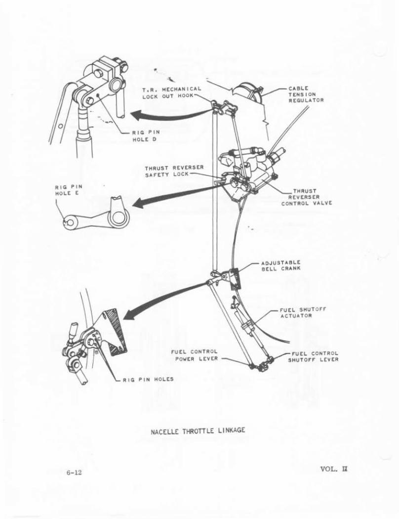
NACELLE THROTTLE LINKAGE
6-12
CAIILE TENSION REGULATOR
THRUST REVERSER
CONTROL VALVE
ADJUSTAIILE BELL CRANK
F"UEL sHuTo rr ACTUATOR
F"U EL CONTROL SHUTOrr LEVER
VOL. D
0> I ..... ...
RIG I'IH HOLtS
ADJUST AHQLt 3
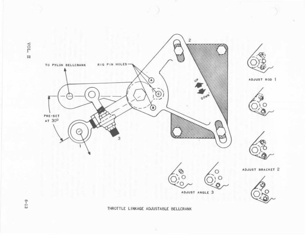
THROTTLE LINKAGE ADJUSTABLE BELLCRANK
AOJUST ROD I
ADJUST BRACKET 2
ENGINE CONTROL LINKAGE.
The engine control linkage begins with the cable tension regulator bellcrank. The bellcrank is attached to the ~tput shaft of the cable tension regulator. A pushrod and a linkrod transmit throttle power requirements to the fuel control and the thrust reverser control valve. The bellcrank also has a roller hook for the thrust. reverser lock-out latch. A rigging pin hole is provided in the bellcrank for cal)le tension, regulator and engine control linkage rigging. Tho fuel control p1.1.8hroa from the bellcrank connects to the fuel control crank assembly. The crank assembly is mounted to a serrated plate and bracket which Is attached to the right side of the engine compressor section at flange G. Serrations are used as an aid in rigging the engine control linkage. There are three rigging holes in the bracket and plate which align with the lobe of the crank when the fuel control crank arm is in the full forward power, partial power, and full reverse power positions. A push rod connects the crank assembly to the fuel control cranlt arm. The fuel control crank connects to the fuel control power shaft through a serrated mating device. A part power stop is located on the fuel control which is used in rigging the engine fuel control crank position w1th the use of a power level angle rigging tool. After the rigging and adjustment of the part power stop, it is rotated 180 degrees to its stowed position and Is safety wired. The part power stop is used for engine part pOwer trim by maintenance personnel. Also provided on the fuel control is the maximum forward thrust adjustment stop and the full reverse thrust adjustment stop.
FUEL SHUTOFF ACTUATOR.
Operation of the fuel shutoff crank arm on the fuel control Is accomplished by an electric actuator. There are two positions of the fuel shutoff crank arm, fully open or fully closed. The actuator Is operated by the FUEL AND START IGNITION switch located on the pilot's overhead panel. The actuator Is also controlled by the fire emergency handle. When this handle is pulled, fuel Is shut off at the fuel control by the fuel shutoff actuator and the cable actuated fuel shutoff valve, located on the front spar of the wing at the top of the pylon, Is mechanically closed.
THRUST REVERSER CONTROL LINKAGE.
The link rod from the cable tension regulator bellcr ank connects to the thrust reverser control valve crank arm. This mechanical linkage operates the manual pilot valve. A rigging pin lobe is provided at the crank arm for rigging the thrust reverser control valve linkage to the fuel control linkage. A thrust reverser control valve interlock is incorporated. This system keeps the dlrectioo.al control valve in the forward thrust posttlon while the engine is operated in the FUGHT RANGE which maintains the thrust reverser doors in the "RETRACTED" position.
The interlock consists of a striker lever on the thrust reverser control valve
6-14 VOL. II
assembly, a lock for the directional control valve spool, a striker lever, and a striker button attached to the fuel control upper pushrod. The striker lever is spring-loaded to "LOCK." When the throttle is moved to the thrust reverse range, the thrust reverser interlock is actuated and unlocks the spool of the directional control valve so that hydraulic power is ported to the thrust reverser target door actuators on the extend end.
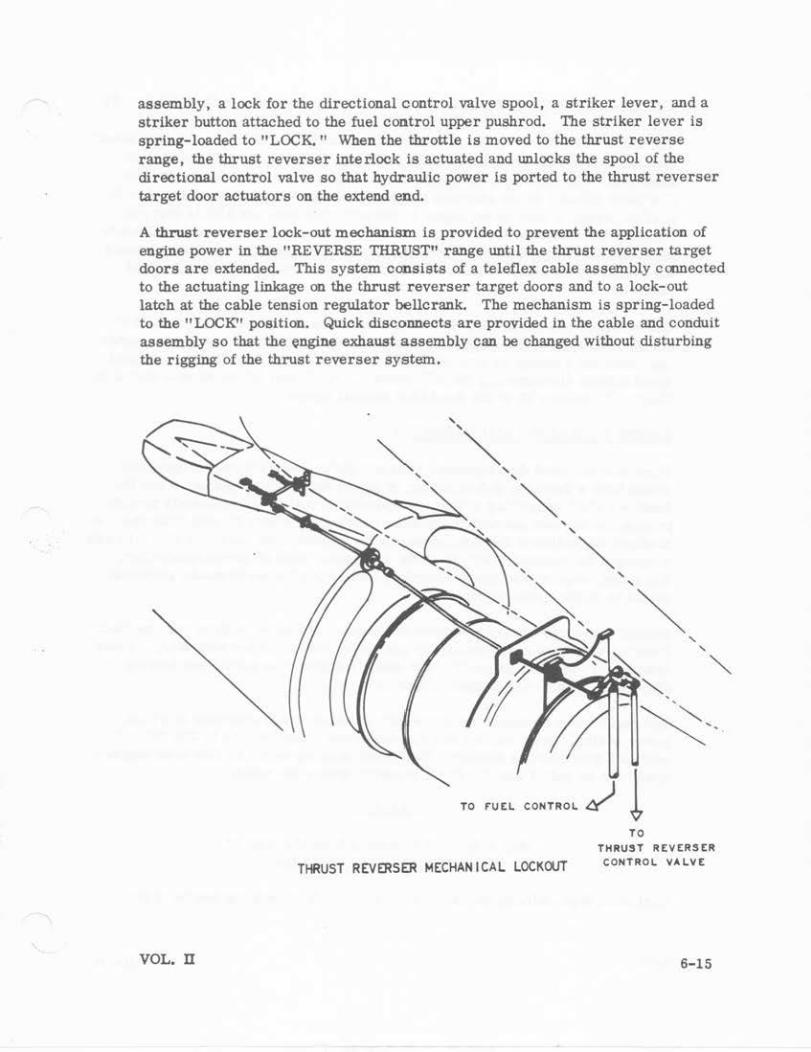
A thrust reverser lock-out mechanism is provided to prevent the application of engine power in the "REVERSE THRUST" range until the thrust reverser target doors are extended. This system consists of a teleflex cable assembly cc:nnected to the actuating linkage on the thrust reverser target doors and to a lock-out latch at the cable tension regulator bellcrank. The mechanism is spring-loaded to the "LOCK" position. Quick disconnects are provided in the cable and conduit assembly so that the engine exhaust assembly can be changed without disturbing the rigging of the thrust reverser system.
VOL. ll
' '~
' '
~ ' '
~
TO rUEL CONTROL
THRUST REVERSER MECHANICAL LOCKOUT
' '
~
TO
' '
THRUST REVERSER CONTROl VALVE
6-15

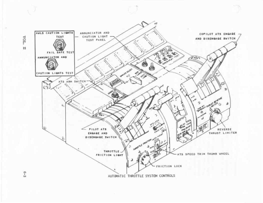
AUTOMATIC THROTTLE SYSTEM (ALL WEATHER LANDING SYSTEM ONLY).
The major components of U:te Automatic Throttle System (ATS) are the computer/ amplifier un1t, servomotor as§_embly, clutch pack assembly, and speed trim assembly. The ATS uses the al"rspeed hold signal from the Central Air Data Computor (CADC) as the airspeed source. A clutch-operated synchromotor Is used to present a zero error signal to the computer until the ATS is engaged. When the ellot engages the system, a CADC signal engages the synchroclutch to the indicat5-4llrspee(l shaft. Thereafter, until disengaged, the signals through the conlputer/ampllfier to the servomotor are proportional to aircraft speed changes.
The servomotor positions the throttles to maintain the speed of the aircraft at the time the system was engaged. The pilot, by adjusting the speed trim signal, can command a change in aircraft speed up to * 5 knots of the original engaged speed without disconnecting the ATS system. Additional information is shown In Chapter 5, Vohune IX of the Star Lifter manual series.
ENGINE OPERATION AND TRIMMING.
Personnel assigned the responsibilities and duties i.Dyolving engine operation should have a thorough understanding of engine design characgerlstics and the functions of all supporting systems. Operational maintenance manuals provide procedures !or safe operations includ.ln& check lists of step by step functions. A preillgbt inspection of the aircraft should be performed to ascertain that it is safe to operate the engines. Only essential personnel, such as ground controller, fire guard, support equipment operator, and supporting moJ.ntenance personnel, should be in the operating vicinity.
Several dangerous areas and factors are involved when jet engines are operated. Knowledge of these areas and safety precautions required are necessary. Noise intensity of operating jet engines can cause temporary or permanent hearing damage. Adequate ear protection should be utilized.
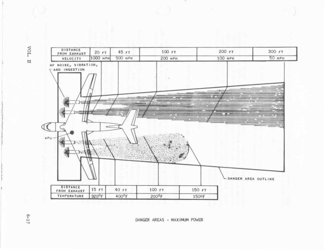
The engine inlet is dangerous, especially if the engine Is operating at a higb, power setting. Mass airflow Into the Intake can range from 50 to 300 PSI and acts as a giant vacuum cleaner. Personnel standing within 25 feet of an engines intake can be pulled into it: Death Is nearly always the result.
WARNING
Stay at least 35 feet away from the front of the intake of an operating jet engine.
Similarly, high-velocity gases are ejected through the exhaust nozzle of the
6-16 VOL.·II
l
I • l
I • I
Hr NOISE, VIBRATION, ANO INGEST I ON
15 FT 40 rT
100 rT 200 H 300 rT
DANGER AR[A OUTLINE
100 rT 150 n
DANGER AREAS - MAXIMUM POWER
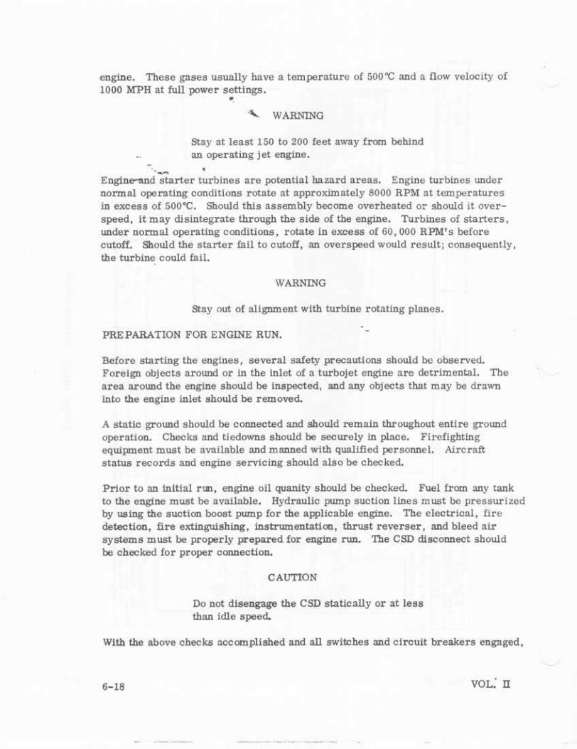
engine. These gases usually have a temperature of 500"C and a flow velocity of 1000 MPH at full power settings . ..
""- WARNING
Stay at least 150 to 200 feet away from behind an operating jet engine .
• Engine--and";tarter turbines are potential hazard areas. Engine turbines under normal operating conditions rotate at approximately 8000 RPM at temperatures in excess of soo•c. Should this assembly become overheated or should it overspeed, it may disintegrate through the side of the engine. Turbines of starters, under normal operating conditions, rotate in excess of 60,000 RPM's before cutoff. Should the starter fail to cutoff, an overs peed would result; consequently, the turbine could fail.
WARNING
Stay out of alignment with turbine rotating planes.
PREPARATION FOR ENGINE RUN.
Before starting the engines, several safety precautions should be observed. Foreign objects around or in the inlet of a turbojet engine are detrimental. The area around the engine should be inspected, and any objects that may be drawn into the engine inlet should be removed.
A static ground should be connected and should remain throughout entire ground operation. Checks and tiedowns should be securely in place. Firefighting equipment must be available and manned with qualified personnel. Aircraft status records and engine servicing should also be checked.
Prior to an inltial run, engine oil quanity should be checked. Fuel from any tank to the engine must be available. Hydraulic pump suction lines must be pressurized by using the suction boost pump for the applicable engine. The electrical, fire detection, fire extinguishing, instrumentation, thrust reverser, and bleed air systems must be properly prepared for engine run. The CSD disconnect should be checked for proper connection.
CAUTION
Do not disengage the CSD statically or at less than idle speed.
With the above checks accomplished and all switches and circuit breakers engaged,
6-18
..
the aircraft and engines are in a ready-state for an engine run.
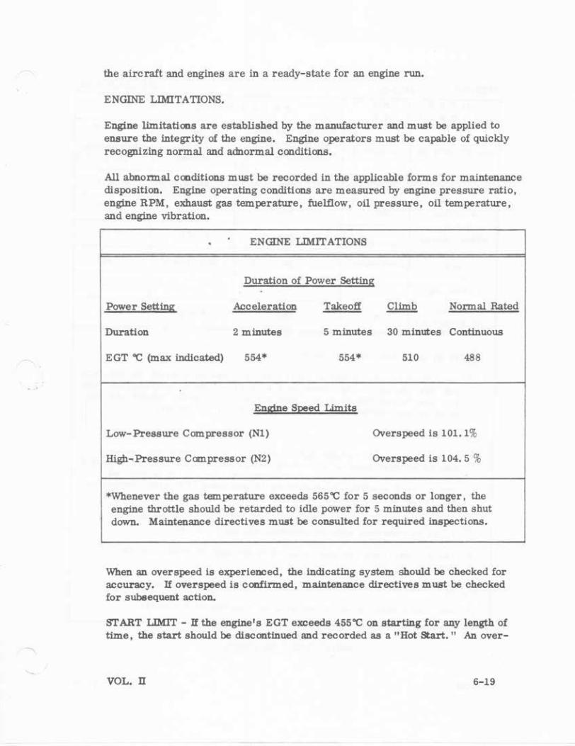
ENGINE LIMITATIONS.
Engine limitations are established by the manufacturer and must be applied to ensure the integrity of the engine. Engine operators must be capable of quickly recognizing normal and adnormal conditions.
All abnormal conditions must be recorded in the applicable forms for maintenance disposition. Engine operating conditions are measured by engine pressur'e ratio, engine RPM, exhaust gas temperature, fuelflow, oil pressure, oil temperature, and engine vibration.
. ENGINE LIMITATIONS
Duration of Power Setting
Power Setting Acceleration Takeoff Climb Normal Rated
Duration 2 minutes 5 minutes 30 minutes Continuous
EGT 'C (max indicated) 554* 554* 510 488
Engine Speed Limits
Low-Pressure Compressor (N1) Overspeed is 101.1%
Higb~Pressure Compressor (N2) Overs peed is 104.5 %
*Whenever the gas temperature exceeds 565'C for 5 seconds or longer, the engine throttle should be retarded to idle power for 5 minutes and the11 shut down. Maintenance directives must be consulted for required inspections.
When an overspeed is experienced, the indicating system should be checked for accuracy. If overspeed is coofirmed, maintenance directives must be checked for subeeqU81lt action.
START LIMIT - If the engine's EGT exceeds 455'C on starting for any length of time, the start should be discontinued and recorded as a "Hot Start." An over-
VOL. U 6-19
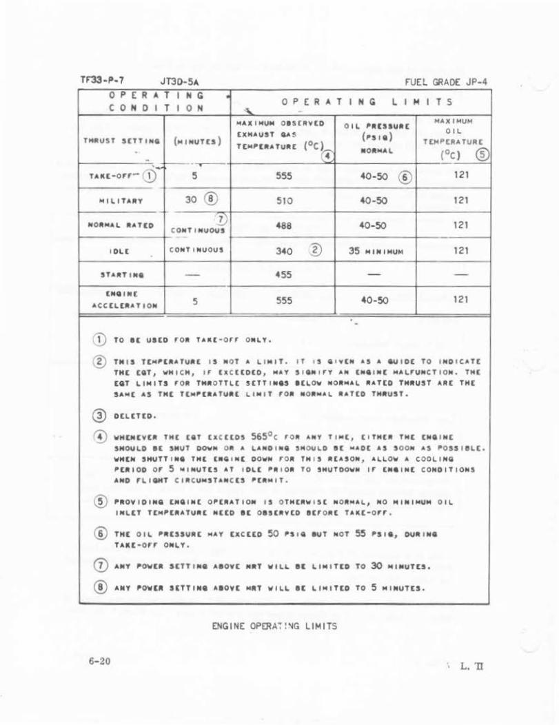
TF33-P-7 JT30-5A FUEL GRADE JP-4 0 PER A T I H G • 0 P E R A T I H G L I~ I T S C 0 H 0 I T I 0 H
" MAXIMUM OI SCAVlD OIL 'IIESIUIIl MAXIMUM
UHAUST GA~ ('Sill) OIL
THAVST S£TTIHII (HI NVT£S ) (oc) TI:HPERA TURt T(H,[IIATUA[ •OIIHAL (oc l ® . i'.i' -::.- f.-- --.--.
u "'-o rr- Q) 5 555 40-50 ® 121
-"ILITAIIY 30 ® 510 40-50 121
·- !) NO .. MAL RATIO 488 40-50 121 COIOT INUOIIS
I DL[ CONT I NUOUS 340 1) 35 HIM I HUH 121
STAAT 110• - 455 - -lNIIIIO[
555 40-50 121 ACC[L[AATI ON 5
. -CD TO I[ UltD f"OA TAKl •Orr ONLY.
® TMIS T[H,[AATUAt IS MOT .. LI MI T . IT t S Q t V(N AS A 6UtOE TO I ND ICAT[ THE (liT, WH ICH, " U CUDED , N.V S IGN t r'f AN tNetN[ MALrUHCTION. THE lilT LIMITS f"OA TMAOTTL C S(TTIIO.S I(LOW NOA.,AL AAT[O TMIIUST ARt THE SAN( AS TNt T(M~(aATUat LtNIT roa MOaMA l AAT[O THaUST.
@ DtLtT[O.
~ WH[M[VU THC teT u c ttos 565°C f" OA ANY TIN[ 1 ( ITM[A TN[ [1011 IN[ SMOULD 8[ SMUT oov• o• " LAN01N8 'MOUL D St MAO[ AS SOON AS ~OSS I 8l(.
WNlN SHUTTINII TNt £•GIN( OOWN ro• TH I S A[ASON 1 AL.LOW A COOLING ,tAIOD o r 5 "IHUTlS AT I DL[ ,A I OA TO SHUTDOWN If" [IO.IN[ CONDITIONS AND f"L IQMT CI ACUNSTAN C[S ,[liM IT.
® ,ROYIDINQ [NIIIN[ 0' tAATION I S OTHtlitW IS [ N 0 11tMAL 1 NO fi41NI,..UM OIL IHL[T TlH,[AATURC N[[D 8[ OIS[RYED 8[f"OAt TAKE-orr.
® TH[ OIL 'AlSSUAE .,,.y [XC[[D 50 'SIQ IUT NOT 55 'SI., DUA l lOll TAK[•Of"f" ONLY.
0 AMY 'OWl A snT I N II ••ovc "RT It ILL ., LIMIT[O TO 30 MIMUTES,
® ANY 'Oit[A StTTINe A lOY[ MilT It ILL ., LINITtO TO 5 MINUTES.
ENGINE OPERA:! ~G LIMITS
6-20 L. 'II
temperature inspection must be performed before a restart is attempted.
FALSE START- If an engine ignites normally but does not accelerate, the start must be discontinued and a second start attempted. If the second start is unsatisfactory, the engine must be shut down and an investigation made.
A false start may be the result of insufficient power to the starter or early starter cutout. The starter must assist the engine up to 35 peroent speed for a successful start. (The indicatioo of the starter valve light during the second start should be noted. )
NOTE
. After a false start, rotate the engine with the starter for 10 to 15 seconds to remove accumulated fuel or vapor frcm the engine before attempting a restart.
STARTER DUTY CYCLE- The starter duty cycle follows:
One minute "ON," 30 seconds "OFF"
One minute "ON," 30 seconds "OFF''
One minute "ON," 30 minutes "OFF"
The starter may be operated for 1. 5 minutes "ON," and 10 minutes "OFF" for any number of duty cycles.
FUEL AND OIL LEAKAGE - During engine operation, the drain mast and lower cowl area must be observed for liquid leakage. If any leakage is observed, the engine should be shut down and an investigation made. After engine run, the nacelle cowling must be inspected for leakage.
ENGINE STARTING.
Before the starting operation is begun, the parking brakes should be set by using the No. 3 hydraulic system pump until the engine is started. The pump need not be run continuously, but accumulator pressure must be kept above 2000 PSI. With the fuel and lgnitioo switch in the "STOP ' position, the throttle lever is placed in "IDLE START." The pyloo bleed air duct and the APU valves, if required, should be opened. The fuel boost pump should then be turned on and the corr esponding low-pressure fuel light should go out. Thrust reverser lights should be "OFF." If the thrust reverser NOT-LOCKED light is "ON," thereverser should LOCK as the engine is started.
VOL. ll 6- 21

"' z
X L
"' ... " w .. "' w ..
C-141A INSTALLAT ION Of Tf33-P-7 TURBOFAN ENGINE • IDLE S~EED TRIM CURVE STATIC CONDITIONS
58
t- .... . r--1-- - .......... COCKPIT INSTRUMENT ·-~ r-.... /
f- MAX
r-- - -~~ r-- r-.... 1-
57
r-- -~--t-- r-- 1--- 1--r-- ..... 1--
~- ~- t-- ~ 56
1 -t-- r--r-- '- MAX ITR IM I 80)(
~--- ...... '-MIN COC KI' IT - - ..... "'- - MIN TRIM 8 0 X
INSTRUMENT r-. I-- r=:-55
·~ t- - r-_ 54
-20 0 20
-6.7 40 4.4
60 15 .6
80 26.6 -28.9 -17.8
OAT - OU TS ID E AMBIENT TEM~ERATURt
IDLE SPEED TRIM CURVE
I
The engine start button should now be depressed. The button will hold in and the button and starter valve light will illuminate. If oil pressure and :-11 RPM do not indicate within 20 seconds, the engine must be shut down.
Only the N2 rotor section is driven by the starter. Air is pumped into the engine through Nl which r esults in Nl rotation. The engine must be rotated by the starter to approximately 10 percent RPM to provide sufficient airflow !or combustion. At 10 percent N2 RPM, the ignition and fuel switch should be posi~oned to "RUN. " Fuelfiow and EGT will be indicated and the N2 RPM will continue to accelerate.
6-22
NOTE
Maximum EGT at start is 455'C not to exceed 15 seconds. If EGT does exceed these limits, shut down the engine immediately.
VOL. n

The engine's RPM will continue to accelerate by both starter power and heat energy driving the engine's turbines. The fuel control provides the fuel metering in accordance with the changing engine parameters.
At 35 to 45 percent RPM, the starter button will pop out, and the button and starter valve position lights will go out. U the button does not pop out by 45 percent RPM, the button should be pulled manually and the starter system checked. The engine's operation is now seU-sustalnlng. The fuel ccotrol provides for the ccotinued acceleration to idle speed, 54 to 58 percent depending on the ambient air temperature. The following table shows the normal engine idle configuration:
NORMAL ENGINE IDLE CONFIGURATION
ITEM
N2RPM
Nl RPM
Oil Pressure
Oil Temperature
Hydraul-Ic Pressure
Generator
EPR
FueUlow
CSD Oil Temperature
ENGINE SHUTDOWN.
CONDITION
54 to 58 percent
25 to 30 percent (reference only)
35 to 45 PSI
40 to 121 'C
3000 PSI ± 150
400 Hertz± 4
Bottom of scale
700 to 1500 PPH (reference only)
40 to 150'C
U the engine has been operated at normal rated power or above for 1 mtnute or more, the engine must be run at "IDLE" for 5 minutes to allow the enging to cool and to prevent possible rotor seizure during coastdown. The engine throttle should be moved to "IDLE" and, after sufficient cooling, the fuel and Ignition switch should be positioned to "STOP. " The fuel boost pump sWitch should also be positioned to "OFF." Engine RPM, EGT, and engine oil pressure should decrease. Fuel should drain from the drain mast immediately thus indicating that the fuel dump valve has opened.
VOL. n 6-23
Nl and N2 RPM gages should indlcate free deceleratioo of the compressors. Nl will require approximately 2 to 3 minutes to reach zero RPM .
• ENGINE TRIM.
The primary purpose of engine trimming is to ensure thAt the engine produces its rated thrust within a wide range of atmospheric conditions. Trimming is based upon the measurement and adjustment of exhaust nozzle pressure (P+7). The adjusgnehts on the' fuel control enable the governed speed to be varied within specified limits. Varying the engine RPM results in a proportional change in engine exhaust gas pressure and thrust. A manifold pressure gage Is used In trimming the engine, as a re the EPR gage, RPM and EGT indlcators. Trimming should be accomplished whenever a new or overhauled engine is inst:llled oo the aircraft and when a fuel control luis been replaced or rerigged.
The aircraft must be beaded dlrecUy into the wind and wind velocity must not exceed 8 to 10 knots. Trunmmg should never be attempted when Icing conditions prevail. lt is also necessary that all engine controls be properly rigged or checked before engine trimming Is attempted. The appropriaw maintenance dlrectives should be consulted for proper throttle rigging proceJure.
Testing equipment needed for engine trim follows:
6-24
o Jetcal Analyz·er (Bowell Instruments lnc. ) (Hl20-5119)
CAUTION
This Wlit is used to measure EGT, RPM and pressures during engine tJ."im. The unit checks out the engine instrument system as well as the engine's performance.
Do not use aircraft instrwnents for trimming.
o Remote Trim Control Box (FSN 4920-589-9624)
o Remote Trim Servo Rotary Actuator (FSN 4920-654-8434)
o Remote Trimmer Adapter (FSN 4920- 344-3027)
This box is used to remotely adjust the fuel control trim screw.
This Wlit is used ln conJunction with the remote trim control box to provide power to adjust the fuel control trim screws.
This unit connects the remote trim servo rotary actuator to the fuel control.
VOL. n
RU40TE TR 1>4
CONTROl 80X
,--------l I I I
I I
REMOTE TRIM I CONTROl 80X POIICR SUPPlY
CA8lt -i---------~1.
J(TCAl ANALYltR
I I I I I I L
AIR CRArT rL ICHT STATI ON
CONTROL BOX-TO-ROTARY
SCAVO ACTUATOR CABlE
ROTARY SERVO
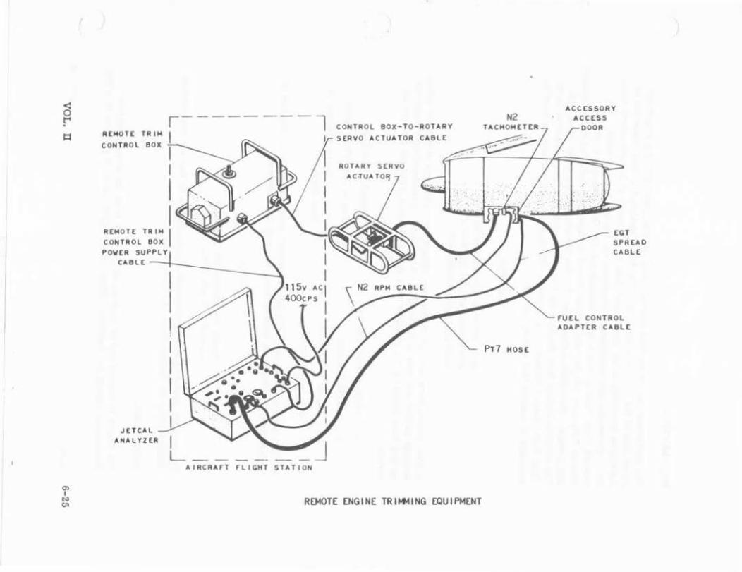
ROOTE ENGINE TRII+IING EQUIPMENT
N2
PT7 HOSE
ACCESSORY ACCESS
DOOR
rutl CONTROL AOAI'TER CA8Lt

PREPARATION.
The part power stop of the ftl.el control should be positioned with the stop in the direct path of the throttle cr~m. The.Jetcal analyzer is then connected to the engine according to the instruction pl.ate on the inside of the nnalyzer' s cover lid. Operntional and maintenance directives for the unit must be used. The Remote Trim Control Box is then connected to the Jetcal analyzer, and the Remote Trilll;mer Ada~ter and Remote Power Actuator are installed to the engine's fUel cont.t.ol. 1\taintenance directives for this installation should be consulted. The electrical cable !ram the Remote Trim Control Box is then connected to the Trim Servo Rotary Actuator. A 115-volt, 400 Hertz A-C power source must be available to operate this test equipment.
CAUTION
Make all trim adjustments with the Jetcal analyzer and~ with the aircraft engine instruments.
A trim record form is required for recordiDg all test readings at various power settings and for analysis of the results. The followiug.information is required on this form which can be obtained !ram the engine data plate and the aircraft forms.
0 Engine Serial Number 0 Aircraft Total Time
0 Engine Position 0 Engine Data Plate Speed
0 Engine Total Time 0 Part and Serial Number of
Aircraft Number Fuel Control
0
Outside Air Temperature (OAT) and barometric pressure within 30 minutes of engine trimming should be read by using accurate instruments.
NOTE
Do not use barometric pressure corrected to sea level.
The trim kit should be kept in the shade of the airplane so that the temperature obtained from the thermometer is a true reading of OAT.
PROCEDURE.
The engine is started and all instrument readings from the aircraft engine instruments should be observed. When "IDLE" RPM (54 to 58 percent N2 RPM)
6-26 VOL. U
is reached, all engine instruments must be checked for correct reading. The throttle should then be advanced to the part pow~r stop to fully in1late the fan seals. The throttle is then retarded to "IDLE." The fan discharge ducts and Jneumatic ducts must be checked for leakage in all accessible areas with the engine running at "IDLE" prior to the trim procedure. Air bleed must be "OFF." Accessory loads must be reduced to a minimum.
Wtth the engine idling, the N2 RPM should be read from the analyzer and sho·ild be recorded on the Engine Trim form. COLD IDLE RPM is the ini.:ial reading after the engine start before the engine has been stabilized and trimmed.
The throttle control is then moved slowly rearwa.rd through the throttle gate. This movement snould be stopped when the RPM stops decreasing and begins increasing. The chan~e indicates thnt the throttle cootrol is on the fuel control cam Idle fiat. If N2 RPM should drop more than 2 percent, the throttle cootrol rigging must be checked. If the throttle rigging is correct, the fuel control tm.it is at fault and should be replaced.
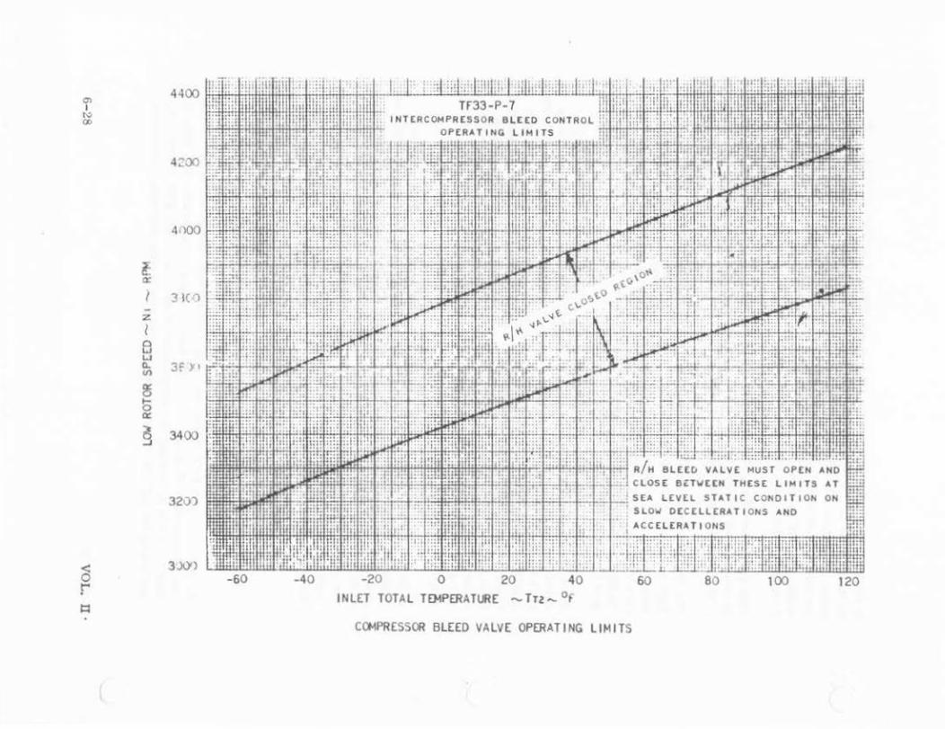
From the ld!c position, the throttle should be moved until the N2 tachometer indicates 80 percent. At this point, the throttle is moved forward very slowly until an increase in EPR ls observed. If this 1Dcrease is observed, the Nl RPM should be recorded. Advo.ncing the throttle to the part power stop at this time ensures full lnfiation of the nacelle seals. While the throttle Is slowly retarded fran the part power positioo toward SO-percent N2 RPM, the EPR should be observed closely. When EPR drops, the Nl RPM should be recorded. This check determines the closing and opening range of the right-hand Bleed Control Function chart.
A stabilization period allows the engine to expand until the engine parts stop expanding and hold steady. This action is accomplished by the throttle being set at the part power position and being held there for a minimum of 5 minutes. Stabilization is indicated by a constant EGT and EPR. Status of the engine during the transition is class!Iied as a change o1 the engine from cold to hot. When the engine reaches a steady stabilized condition, the following must be read and recorded on the work sheet:
o EPR o Nl and N2 RPM
o EGT, Fuelflow o 011 Pressure and Temperature
o pt 7 (inches of mercury) o Vibration, 'ilgb and Low
By performing an EGT sprc~ct test with a Jetcal Analyzer during a "hot" engine run, excessive EGT of any individual thermocuuple is indicated. The sj:.read check Is made by reading the temperature of each individual EGT thermocouple and noting the difference between the lowest and highest readings. Excessive
VOL. n 6-27
"' I
"" 00
l: a:
z I 0 w w (L
"' 3 b 0::
~
4000
31(1)
3f )It
3400
INLET TOTAL Tf>IPERATIJl( - Tn- 0 f
COMPR(SSOR Bl££0 VALV( OPERATING LIMITS

E GT spread can be an indication of defective fuel nozzles. A stabilization pedod of 1 tninute Is required for the engin'! to stabilize at Idle RPM before the N2 :;peed Is recorded. This Is the Hot Idle RPM. If the reconled readings obtained during the engine run are within the limits of the trim charts, idle RPM charts, and bleed valve charts, the engine is properly trimmed.
TRIM ADJUSTMENTS.
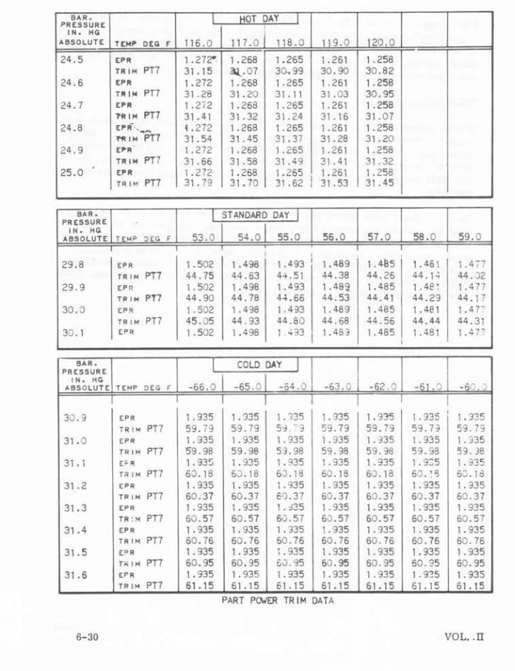
If trim adjustments are necessary, the "MIL PWR" adjustment screw on the fuel control is turned either to increase or decrease Pt 7 while the engine is running at part power speed. The. actual Pt 7 should be within the limits of the desired Pt 7 for the existblg ambient conditions of the day. When Pt 7 is changed, the Idle RPM changes. Necessary adjustments should be made to correct the N2 Idle RPM.
Before a takeoff power check can be made, the part power stop on the fuel control rnust be removed and safetied ln the stowed position. The OAT and barometric pressure rnust be obtained and used to determine the correct EPR for the takeoff power check. The EPR is set to 1. 48 and engu~e speed Is allowed to stabilize. By reading the N2 EPM from the Jete a! Analyzer, the value observed should be within 2.1 percent of the engine data plate speed. The takeoff power check should be within the limits of EPR, EGT, and RPM .
...
VOL. n 6-29
--·----
BAR. I HOT CAY I PRESSURE I IN. HG ABSOLUTE TEMP DtG F 116 .o 117 .0 118.0 119.0 120 .0
24.5 EPR 1 . 272" 1 . 268 1.265 1. 261 1.258 TRIM PT7 31 . 15 a.!... 07 30..99 30.90 30.82
24.6 (PR 1.272 1 .268 1.265 1. 261 1 .258 Tl'liM PT7 31 .28 31.20 31 . 11 31 .03 30.95
24.7 EPR 1 .2i2 1 .268 1 .265 1. 261 1 .258 ?RIM PT7 31 • 41 31 .32 31 .24 31.16 31.07
24.8 t~tl:f · ... _... 1 .272 1 .268 1.265 1. 261 1 .258 "N! IM PT7 31.54 31 .45 3 1 . 37 31 .28 31.20
24.9 (I'R 1.272 1 .268 1.265 1. 261 1 .258 TRIM PT7 31.66 31.58 31 .49 31.41 3 1 .32
25.0 £1'R 1. 272 1 • 268 1.265 1. 261 1. 258 TRIM PT7 31 . 79 31.70 31.62 I 31.53 31 .45
BAR. I STANDARD DAY I PRESSURE .
IN. HG ABSOLUTE TEMP :lEG F 53.0 54.0 55.0 56.0 57.0 58.0 59.0
I I
29.8 EPR 1 .502 1 .498 1 .493 I 1.489 1 . 41!5 1. 461 1.4i7 TRIM PT7 44.75 44.63 4't. 51 44.38 44.26 44. 1 .. 44. )2
29.9 EP R 1.502 1 .498 1 ,493 1.489 1.485 1 . 4e: 1 .477 TRII< PT7 44.90 44.78 44.66 44.53 44.41 44.29 44. 17
30.0 EP!l 1.502 1.498 1 .493 1. 489 1.485 1. 41! 1 1 .47" TR t M PT7 45.05 44.93 44.80 44.68 44.56 44.44 44.31
30. 1 EPR 1 .502 1 .498 1 ~33 1. 483 1. 485 1 . 481 1 . 4 7' I
BAR. I COLO DAY l PRESSURE
-66. 0 I IN. HG -65.0 -64.0 -63.0 -62. 0 -61. D ABSOLUTE .,;.· . TEMP DEG F - \_; . J
I I 30.9 £PR 1 .935 1. 335 1.135 1. 935 1.935 1. 935 1.335
TRIM PT7 59.79 59.79 5>;~ "9 59.79 59.79 59. B 59.79 31 .o EPR 1. 935 1. 935 1. 935 1. 935 1. ~35 1. 935 1. 335
TRIM PT7 59.98 59.98 59.98 59.98 59.98 59.98 59. J8 31.1 E;;.R 1. 935 1 . 935 1 . 935 1.935 1 .935 1. 9::;5 1. 335
T~ IM PT7 60. 18 60.18 6·.) . 18 60.18 60. 18 60 . !<; 60 . 1d 31.2 [PR 1. 935 1 . 935 1 . 'l35 1. 935 1. 335 1. 935 1. 935
TRIM PT7 60.37 60.37 60.37 60.37 60.37 60.37 60.37 31.3 EPR 1 . 935 1. 935 1 . :135 1. 935 1. 935 1. 935 1. 935
TR : >4 PT7 60.57 60.57 60.57 60.57 60.57 60 .57 60.57 31 .4 EPR 1 .935 1. 935 1. 335 1. 935 1. 935 1. 935 1. 935
TRIM PT7 60.76 60.76 60.76 60.76 60.76 60.76 60. 76 31 • 5 CPR 1. 935 1.935 ; . 935 l. 935 1. 935 1. 935 1. 935
r;;11< PT7 60.95 60.95 60.95 60.95 60.95 60.95 60.95 31.6 EPR 1.935 1. 935 1. 935 1 .935 1. 935 1. 935 1. 935
TRIM PT7 61.15 61. 15 61.15 61. 15 61 . 15 61. 15 61. 15 PART POWER TRIM DATA
6-30 VOL •. IT

~ r 1:1
"' I c.> ...
1.14
1.12
~ '-'-" 1 . 08
II
c 0 .. u c ... 1.04 z 0 .. u w c
1.00 c 0 u
l '"' . 96
.92
~
"' ......... ~
-
-60 - 40 - 51. I - 40
I'--..........
-- r-
r- -1-- --
-
-20 -28.9
~"---............
0 -17.8
I
i'-.. ............
20 -6.7
Rf't4 COIIIItCTtO : Rf'M OBSERV[O II ( )el NOT(: 6 ~ ~ ; T : TEMP IN ° 11
0
- .
!',.. 1'--.
!-
I'-. f""... !'-..
40 4.4
60 15.6
~"'--
80 26.7
r---.... -100 37.8
t--
OAT - OU TSID E AH81[HT T[HP[A ATU R[
RPM CO'lRECT I ON C~V(
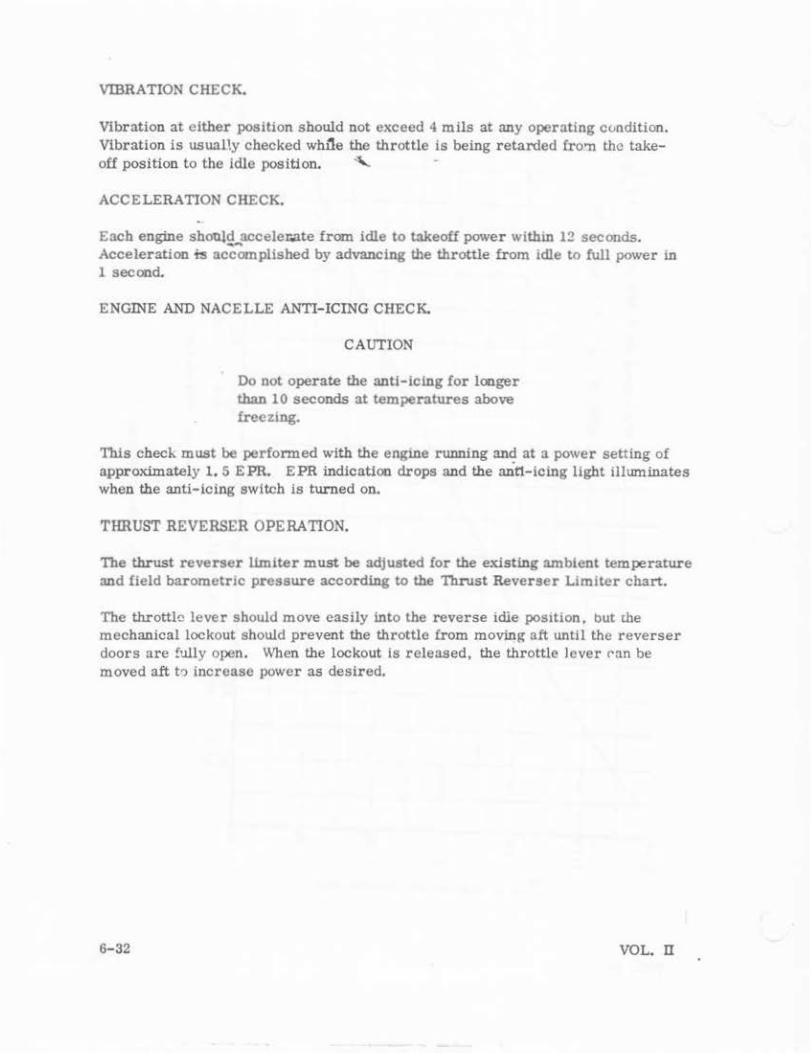
VIBRATION CHECK.
Vibration at either position should not exceed 4 mils at any operating condition. Vibration is USU!llly checked wh~e the throttle Is being retarded fro'll the take-off posi tion to the idle position. "-
ACCELERATION CHECK.
E3Ch engine should 3Cceler.ate from idle to takeoff power withl.ll 12 seconds. Acceleration ~ acc'7xopiished by advancing the throttle from idle to full power in 1 second.
ENGINE AND NACELLE ANTI-ICING CHECK.
CAUTION
Do not operate the anti-icl.ng for longer than 10 seconds at temperatures above freCZI.Ilg.
This chech. must be performed with the engu1e running and at a power setting of approximately 1. 5 E PR. E PR indication drops and the anti-icing light liluminates when the anti-Icing switch is turned on.
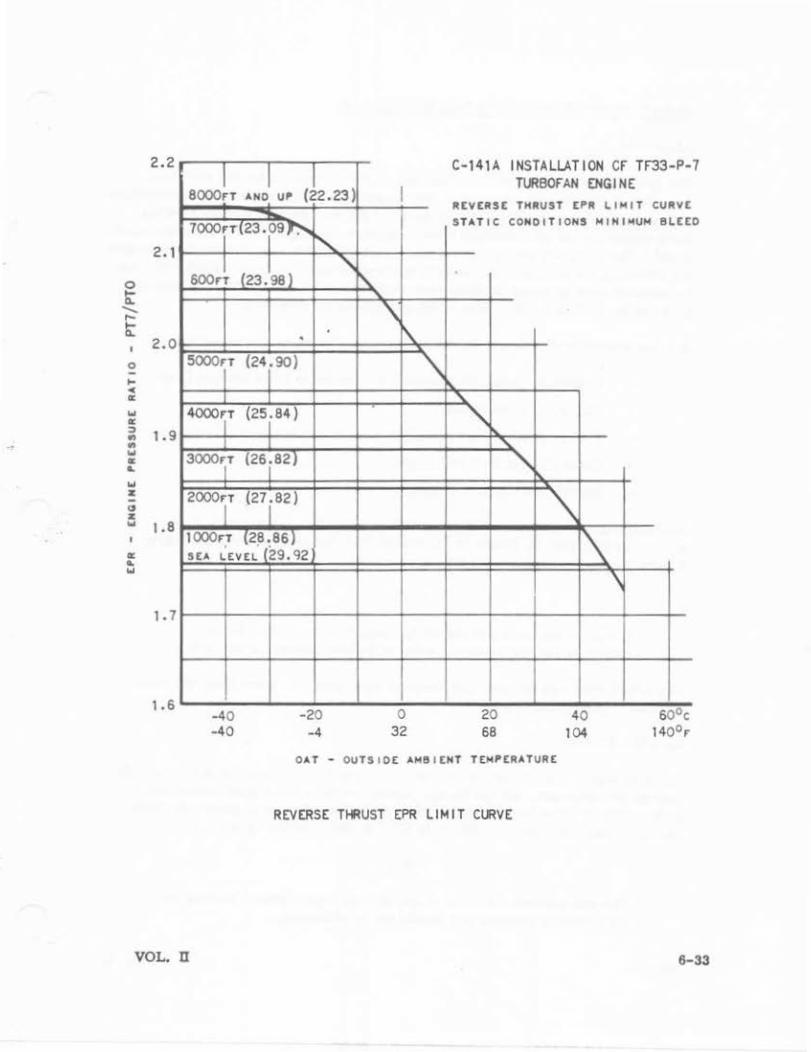
THRUST REVERSER OPERATION.
The thrust reverser limiter must be adjusted for the existl.ng ambient temperature and field barometric pressure according to the Thrust Reverser Limiter chart.
The throttle lever should move easily l.nto the reverse idie posttion, but dle mechanical lockout should prevent the throttle from moving aft until the reverser doors are fully open. When the lockout Is released, the throttle lever ran be moved aft to increase power as desired.
6-32 VOL. ll
2. 2
2. 1
0 t ...... ,... t
2.0 0
... c
" ... " ::> 1.9 ., ., ... "' .. ... z -" z w 1 0 8
" .. w
1 .7
1.6
I I I 8000rT AN~22.23 )
7ooorrT23.o9 • r--...
600r~ (23. 98} '\
' 0
sooor (24i90)
I I
4000~T (25i84)
I I
3000'iT (26 i 82)
2000r (27 i82)
1 ooor; (2!!: 86) SEA lEVE~ (29. 92
I
-40 -20 -40 -4
I
~
'
0 32
'\
C-141A INSTALLATION Cf Tf33-P-Tl-'IBOfAN ENGINE
REVERSE THRUST EPR ~IHIT CURVE STATIC CONDITIONS HINIHUH 8~EE
'" "
20 68
'" ' ~
1'\
40 104
\
OAT • OUTS 10£ AHIII tNT Tt.HPERATURE
REVERSE THRUST EPR LIMIT C~VE
7
0
VOL. n 6-33
POWER PLANT REMOVAL AND INSTALLATION,
REMOVAL,
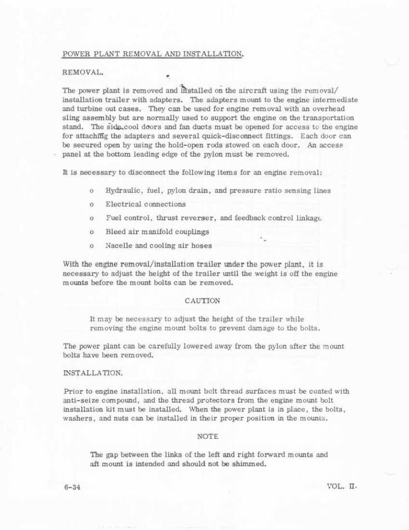
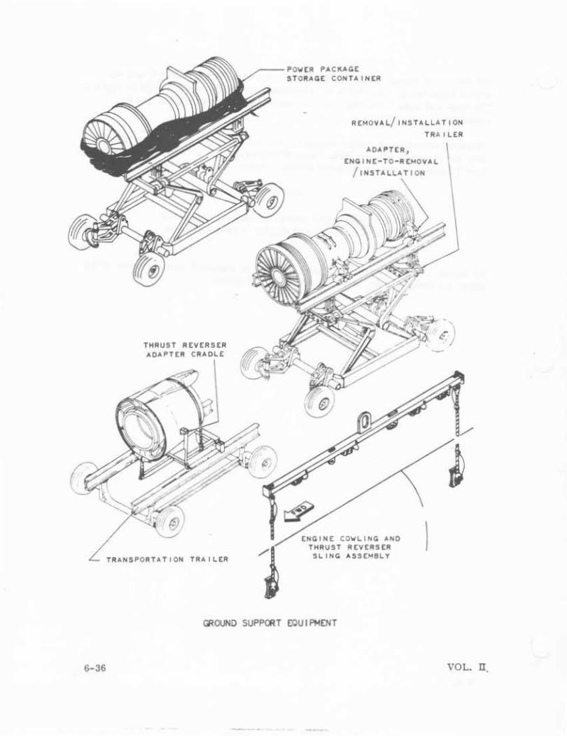
The power plant is removed and 'firstalled on the aircraft using the removal/ installation trailer with adapters. The adapters mount to the engine intermediate and turbine out cases. They can be used for engine removal with an overhead sling assembly but are normally used oo support the engine on the transportation stand. The side-cool doors and fan ducts must be opened for access to the engine for attachi'fig the adapters and se.veral quick-disconnect fittings. Each door can be secured open by using the hold-open rods stowed on each door. An acces$ panel at the bottom leading edge of the pylon must be removed.
It is necessary to disconnect the following items for an engine removal:
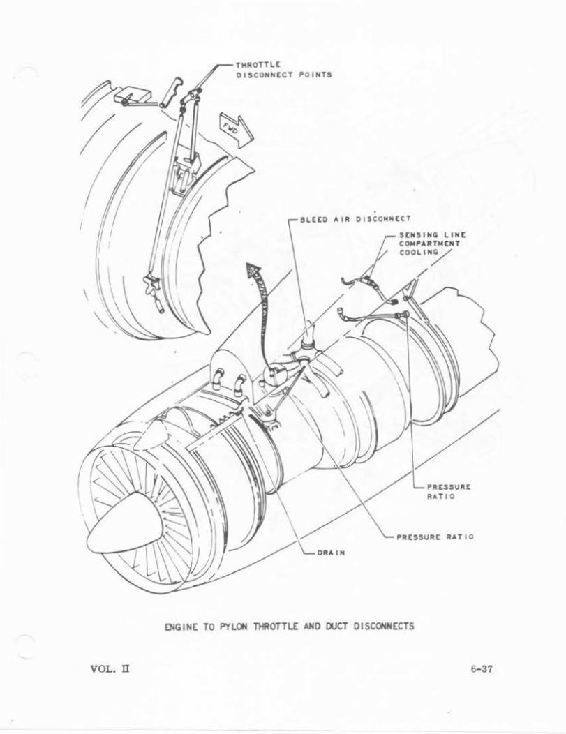
o Hydraulic, fuel, pylon dra.iln, and pressure ratio sensing lines
o Electrical connections
o Fuel control, thrust reverser, and feedback control linkagl.
o Bleed air manifold couplings
o Nacelle and cooling air hoses
With the engine removal/installation trailer under the power plant, it is necessary to adjust the height of the trailer until the weight is off the engine mounts before the mount bolts can be r·emoved.
CAUTION
It may be necessary to adjust the height of the traller while removing the engine mount bolts to prevent damage to the bolts.
The power plant can be carefully lower·ed away from the pylon after the mount bolts have been removed.
INSTALLATION.
Prior to engine installation, all mount bolt thread surfaces must be coated with anti-seize compound, and the thread protectors from the engine mount bolt installation kit must be installed. When the power plant is in place, the bolts, washers, and nuts can be installed in their proper position in the mounts.
6-34
NOTE
The gap between the links of the left and right forward mounts and aft mount is intended and should not be shlmmed.
VOL. II.
'
All electrical wiring, fuel, and hydraulic lines should be connected, and any torque required ns specified In tbe applicable technical manual should be applied. The push rod links to the fuel cootrol, and thrust reverser lockout can be coanected.
Pressure ratio sensing lines, ambient pressure sensing line and pylm dra.ln line, fire detector sensing lines, Zone n cooling ejector air supply line, and Zme I cooling system sensing and pressure lines, can all be connected.
NOTE
A recheck of the engine should be made to ensure that everything is ccmplete and rigging of the controls is
• correct.
All doors , cowlings, and access panels should be installed, and servicing of the engine oil tank, starter, and CSD .should be completed.
VOL. n 6-35
6-36
THRUST REVERSER ADAPTER CRADLE
TRANSPORTATION TRAI~ER
------POWER PACKAGE STORAGE CONTAINER
RtMOVA~/INSTALLATION TRA llER
ADAPTER, ENGINE-TO-REMOVAL
I INSTALLAT ION
ENGINE COWLING AND THRUST REVERSER SLING ASStM8LY
l
• r )
~OUND SUPP~T EOU I PMENT
VOL. n
VOL. n
THROTTLE OISCO"NECT POINTS
&LEEO AIR DISCONNECT
SENSINCO LINE CON"A~TMENT
COOLI N/
"IIESSURE RATIO
ENGINE TO PYLON THROTiLE AND OUCi DISCONNECTS
6-37
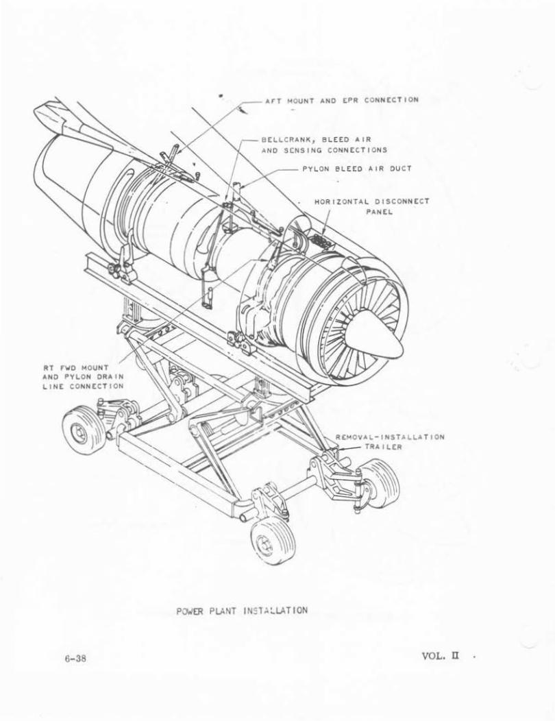
RT rWD MOUNT AND PYLON DRAIN
6-38
• ArT MOUNT AND EPR CONNECTION
BCLLCRANK, BLEED AIR SCNSING CONNECTIONS
eLEED All! DUCT
DISCONNECT PANEL
REMOVAL-INSTALLATION ~-- TRAILER
P(J;IER PLANT I N~V. :.LA T I ON
VOL. n
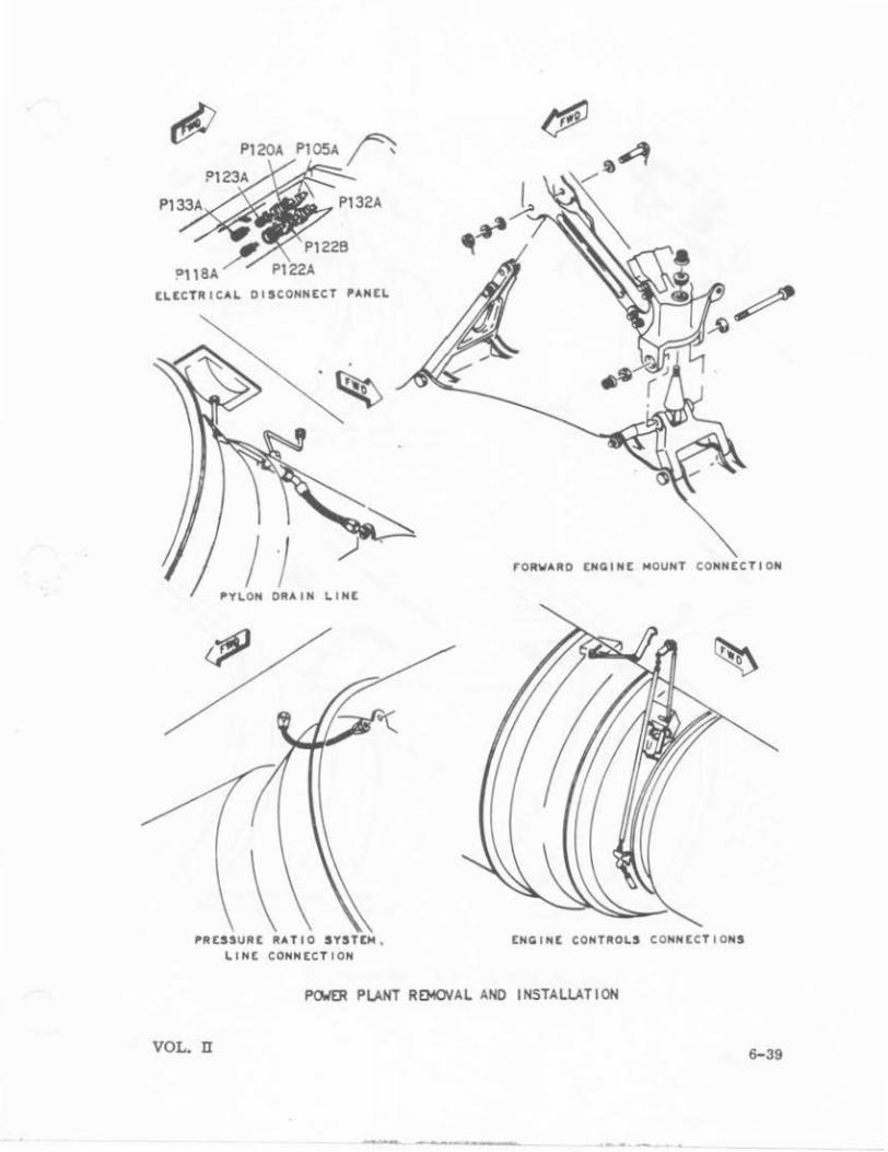
P120A
ELECTRICAL DISCONNECT PANEL
) j rORWARO ENGINE MOUNT CONNECTION
ORA IN LINE
PRESSURE RATIO SYSTEM , LINE CONNECTION
ENGINE CONTROLS CONN ECTIONS
Pa.lER PLANT RE)!()VAL AND INSTALLATION
VOL. n
-- --·---
6-39
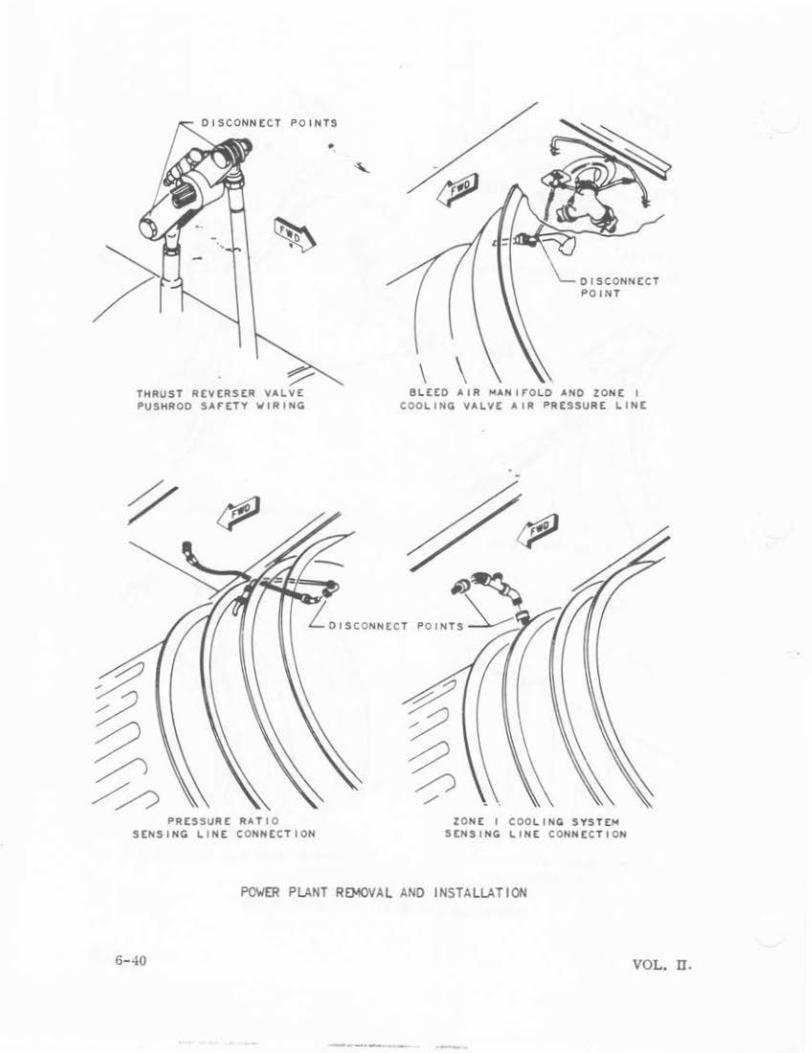
POINTS
THRUST R£V£RS£R VALVE PUSHROD SAFETY WIRING
PRESSURE RATIO SENSING LIN£ CONNECTION
DISCONNCCT
\ \ BL££0 AIR HANIFOLO AND ZON[ I
COOLING VALVE AIR PRESSURE LIN[
ZON£ I COOLI NG SYST£H SENSING LINE CONNECTION
POWER PLANT R0o10VAL ANO INSTALL.AT ION
6-40 VOL. n.
--~--- --

'
t~GI~t ~OU~T eOLT KIT l3S300' &-,m)
T~RtloO covtR (3$300l&-Z35)
T~RtloO covtR l3S300' &-z-31)
VOL· U
BOLT tOOL ~sst~BLV l35300l G· lOl)
l~sTJoLLAT IO~ PAO (35300l &-Z4 l)
Rt~OVAL PIN l3S3()()lo•Z25)
ENGINE ~OUNi SOLi Kli
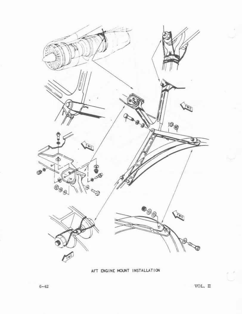
6-42
I NSTALLA T I OH ArT ENGINE: MOUNT
VOL. n

VIEW "B"
B
VIEW "A"
' l'ai\IIARO ENGINE ~T INSTALlATION
VOL. n 6-43
en I
t
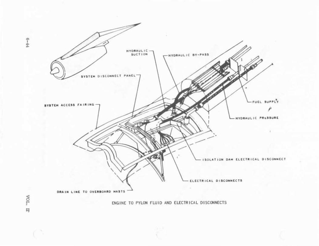
SYST[M DtSCOHN (CT PANt l
IYITlM ACC tSS fA I . ING
t
ISOLATION DAM [L t CT. ICAl OI SCONH tCT
tl t CT . IC Al DI SCONNE CT S
ENGINE TO PYLON fLUID AND ELECTR ICAL DISCONNECTS
(
0> I ...
(11
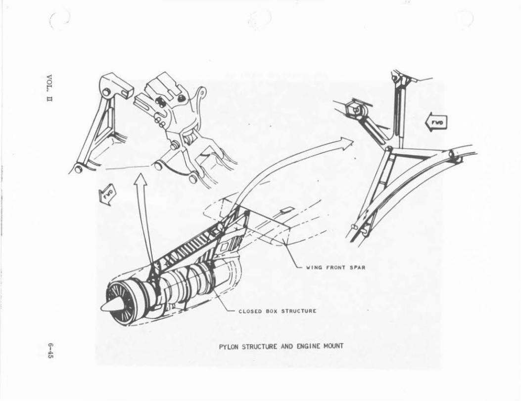
WING fRONT SI'AR
C~OSED SOX STRUCTURE
PYLOH STRUCTIJ!E AND ENGINE MOUNT

.... I
0
APU INTAKE AND EXHAUST DOOR