eng202 – statics lecture 13, sections 6.1-6 - kunetammar.kunet.com/notes/eng202/lecture-13.pdf ·...
TRANSCRIPT
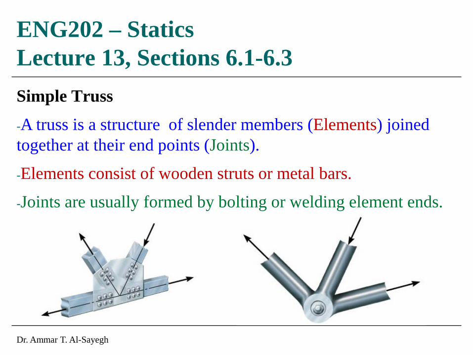
Simple Truss
-A truss is a structure of slender members (Elements) joined together at their end points (Joints).
-Elements consist of wooden struts or metal bars.
-Joints are usually formed by bolting or welding element ends.
ENG202 – Statics Lecture 13, Sections 6.1-6.3
Dr. Ammar T. Al-Sayegh

Dr. Ammar T. Al-Sayegh 1
Planar Truss
-A planar truss is a truss that lies in a single plane, and often used to support roofs and bridges.
-In roofs, loads are transmitted to truss joints by purlins, then to supports by truss elements.
-In bridges, the load is first transmitted to stringers, then to floor beams, then to joints, and finally to supports.
- When a bridge or roof trusses extend over large distances, a rocker or a roller is commonly used for supporting on end. This type of support allows freedom of expansion or contraction of the members due to temperature or application of the load.

Dr. Ammar T. Al-Sayegh 2

Dr. Ammar T. Al-Sayegh 3
-Form of truss must be rigid to prevent collapse.
-Simplest form is a triangle.
-Simple truss can be constructed by starting with a basic triangular element such as ABC and connecting two members (AD and BD) to form an additional element.

Dr. Ammar T. Al-Sayegh 4
Assumption of the Design
1) All loads are applied at the joints.
2) The members are joined together by smooth pins.
-Because of these two assumptions, each truss elements acts a two-force member, and therefore, forces at the ends of the element must be directed along the axis of the member.
- If the force applied to a truss element elongate it, it’s called tensile force. If it shortens it, it’s called compressive force.

Dr. Ammar T. Al-Sayegh 5
The Method of Joints
- To design or analyze a truss, we must obtain the force in each of its members.
- Equilibrium analysis (FBD of entire truss) can not be used as the forces will be internal forces.
- If equilibrium of a joint of the truss is considered, member force become external forces on the joints FBD. Therefore, equilibrium equationss could be used to obtain the magnitudes, which forms the basis for the Method of Joints.
- Rotational or moment equilibrium is automatically satisfied at the joint (pin) and its only necessary to satisfy Σ Fx = 0, Σ Fy = 0 to ensure equilibrium.
- To use the method of joints , it is necessary to draw the joints FBD before applying equilibrium equations.

Dr. Ammar T. Al-Sayegh 6
Procedure of Analysis
1) Draw FBD of a joint having at least one known force and at most two unknown forces.
2) Use one of the methods of establishing the sense of unknown forces.
3) Orient the x and y axes such that the forces in the FBD can be easily resolved into their x and y components and apply Σ Fx = 0, Σ Fy = 0.
4) Continue to analyze each of the other joints.
5) Once the force in a member is found the result can be used to analyze the forces acting on the joint at the members other end.
Recall: Member in compression pushes on joint.
Recall: Member in tension pulls on joint.

Dr. Ammar T. Al-Sayegh 7
Zero-Force Members
- If one is able to determine members supporting no loading, analysis of trusses using method of joint can be greatly simplified.
- Zero force members are used to increase the stability of the truss during construction and provide support if the applied loading is changed.
- These members can generally be determined by inspection of each of its joints.

Dr. Ammar T. Al-Sayegh 8
-If only two members form a truss joint and no external load or support reaction is applied to the joint, the members must be zero-force members.
-If three members form a truss joint for which two of the members are collinear, the third member is a zero-force member provided no external force or support reaction is applied to the joint

Dr. Ammar T. Al-Sayegh 9
Problem 6-1
Determine the force on each member of the truss and state if the members are in tension of compression. Set P1 = 800 kN and P2 = 400 kN.

Dr. Ammar T. Al-Sayegh 10
Problem 6-17
If the maximum force that any member can support is 8 kN in compression, determine the maximum force P that can be supported at joint D.

Dr. Ammar T. Al-Sayegh 11
Problem 6-29
The two-member truss is subjected to the force of 300 kN. Determine the range of θ for application of the load so that the force in either member does not exceed 400 kN (T) or 200 kN (C).