energy utilisation in brick kilnsgkspl.in/.../energy_utilization_in_brick_kilns_presentation.pdf ·...
TRANSCRIPT

Energy Utilization in Brick Kilns
Sameer MaithelPhD Seminar, December 2003
Energy Systems Engineering, IIT Bombay
Supervisor: Prof. A W Date

2
Outline • Introduction• Bull’s Trench Brick Kiln
– Experimental Investigations • mass and energy balance, brick and gas temperature distribution
– Analysis of ground heat loss
• Vertical Shaft Brick Kiln– Experimental Investigations
• mass and energy balance, brick temperature distribution
– 1-D combustion and heat transfer simulation
• Conclusions

3
The Context
Electricity67%
Steel & Washery13%
Others9%
Brick8%
Cement3%
•Important energy consuming industrial end use in India.
≈ 140 billion bricks/yr.
≈Coal: 24 million tons/yr
≈Biomass: >5 million tons/yr
•Environmental concerns: Local and Global
Coal Consuming Sectors

4
Brick Kilns
Intermittent (batch)Kilns1. Clamp2. Scove3. Scotch4. Downdraught
Continuous Kilns1. Moving fire annular kilns
a. Hoffmannb. Bull’s trench kiln (BTK)c. Zigzag etc.
2. Moving ware kilnsa. Tunnelb. Vertical Shaft (VSBK)

5
Important Physical and Chemical Changes during Brick Firing
0 100 200 300 400 500 600 700 800 900 1000
Drying
Clay decomposition and combined water removal (400-600C)
Combustion of organic material (>350 C)
Quartz Inversion (573 o C)
Carbonate decomposition (600-800 C)
Vitrification
Brick firing involves heating, soaking and cooling

6
Brick Kiln: Material Balance
Green Bricks
Air
Fuel
Fired brick
Dry Flue Gas
Water Vapour
Ash
Brick Kiln

7
Heat input (Qin)
1. Fuel added in the kiln (Qfe)
2. Combustible material present inside the brick (Qfi)
1. Convective and radiative heat loss from the outside surface of the overground kiln structure (Q sur)2. Heat conduction to the underground kiln structure (Q gr)
3..Irreversible chemical reactions in the brick (Qr)4. Sensible heat -fired bricks (Qfbr)-dry flue gases leaving the system (Qfg)
5. Chemical energy-CO and other incomplete combustion products leaving the system with flue gas (Qco) -Potential heat in the unburned char in the ash (Qash)
6. Enthalpy in water vapour leaving the system (Qv)• From residual mechanical water in green bricks (Qv, mech)• From combined water generated during the dissociation of clay minerals (Qv,chw)
Continuous Brick Kiln(steady state)
Energy Balance
• From combustion of hydrogen contained in the fuel (Qv,H2)• Moisture in coal (Q v,coal)

Bull’s Trench Kiln (BTK)

9
Rationale for studying BTK• Main kiln: 30,000 kilns; 75% brick production• Literature survey:
– Two experimental studies:Majumdar et al [1968] & TERI [1995]
– No analytical study• Gaps in knowledge
– Incomplete energy balance statements • Qgr not studied • Large unaccounted energy losses.
– Large uncertainties in energy balance components• Qfg (60.8%) in Majumdar; Qfg (7.6%) in TERI.
– Brick and gas temperature distribution not available.– Air leakage in the system not studied

10
BTK – Working PrincipleFlue Gas
Direction of fire travel
Air Entry
Coal Feeding and Fire
Green bricks
Fired bricks
Closed end
11
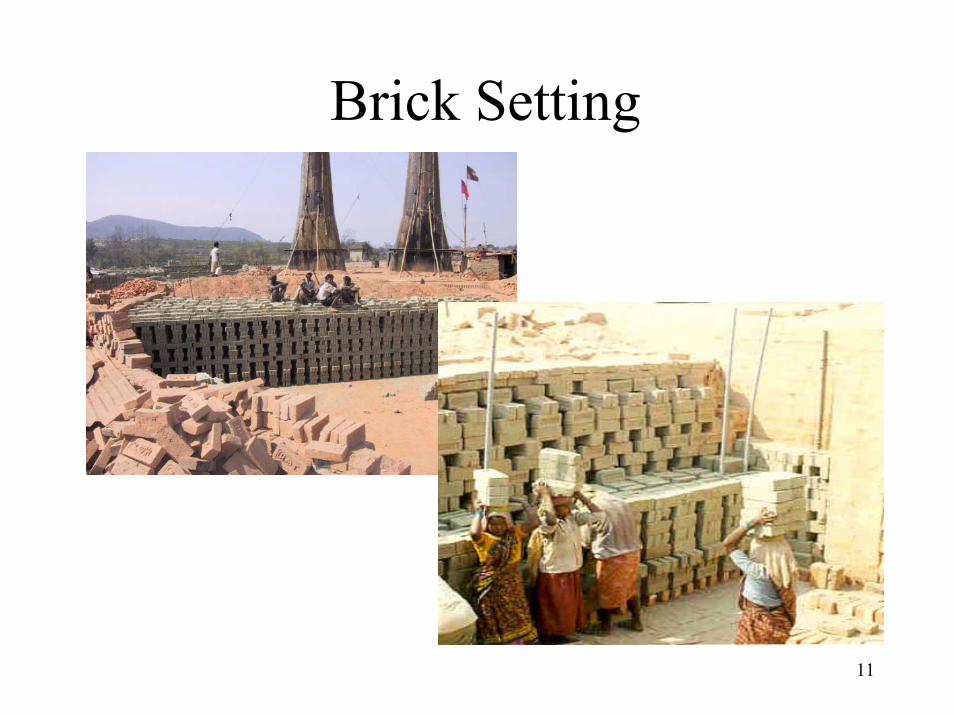
Brick Setting

12
∆
Layer 2-18
Layer 1
Layer 19-20
Coal Feed
L2
L1
L3
L4
L5
∆
-From feed holes on kiln roof
-Manual and Intermittent
-Coal burns on ledges and on ground
Coal Feeding

13
BTK, Kulpi
• Location70 km south of Kolkatta along Hooghly river.
• Preparatory visits: March 1998 & Dec. 1998
• Experiments:- March 10 – April 5, 1999
- Periodic steady-statecondition
- Measurement covering one full firing cycle
14
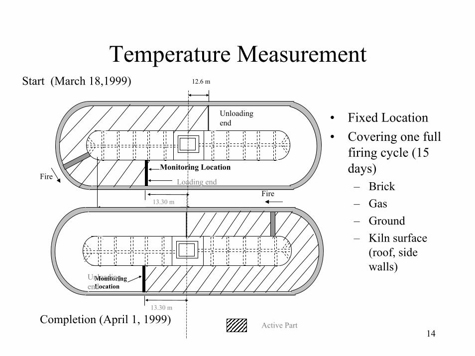
Temperature MeasurementStart (March 18,1999) 12.6 m
• Fixed Location• Covering one full
firing cycle (15 days)– Brick– Gas– Ground– Kiln surface
(roof, side walls)
FireMonitoring Location
13.30 m
29.40 m Active Part
Unloading end
Loading endFire
Monitoring Location
13.30 m
Active Part
Unloading end
Completion (April 1, 1999)
15
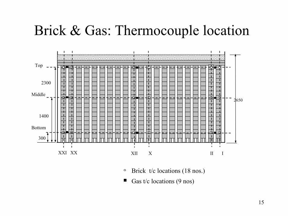
Brick & Gas: Thermocouple location
2650
Top
2300
Middle
1400
Bottom
300
II IXII XXXI XX
Brick t/c locations (18 nos.)Gas t/c locations (9 nos)

16
Brick Thermocouple Assembly
3100
1100 900 800 300
Thermocouple sensor
Ceramic insulators
Junction Box
Extension cables
Ceramic insulator element with six holes (O.D.=16 mm; length = 150 mm
16 AWG Ni-Cr/Al-Cr thermocouple
Thermocouple junction terminated on the stainless steel ring (O.D = 20 mm)
wire

17
Temperature Measurement• Care taken not to introduce any intermediate metal : Extension cables
and connectors of chromel/alumel.
• Extension cable insulation: polyester film, fiberglass braid with varnish impregnation (protection from moisture).
• After connecting thermocouple assemblies with extension cable, checked for reverse polarity at the thermocouple – extension wire junction.
• Temperature scanner: Resolution = 1oC; Accuracy = ±2oC; cold junction compensation using electronic circuit.
• (Frequency of temp. measurement = 900 s) > (Time constant for SSring = 359 s for h=10W/m2K)
• Temperatures manually recorded; frequency of measurement 15/ 30/60 min.

18
Temperature Measurement
Locating brick t/c
Control room being constructed
Tripod stand for hanging t/c s Inside the control room

19
Brick Temperatures
0
200
400
600
800
1000
1200
0 50 100 150 200 250 300 350 400 450 500
Time (h)
Tbr (
o C)
XII -BottomXII-MiddleXII-Top
Coal feeding interval
Removal of the ash insulation
Rectif ication of air leakage around thermocouple assembly
Temperature scanner problem
• Stratification in vertical direction
• Top temperatures – Lower in the firing
zone– Higher in heating and
cooling zone
• Primary Causes– Non uniformity in
gas flow– Non uniformity in
coal distribution
20
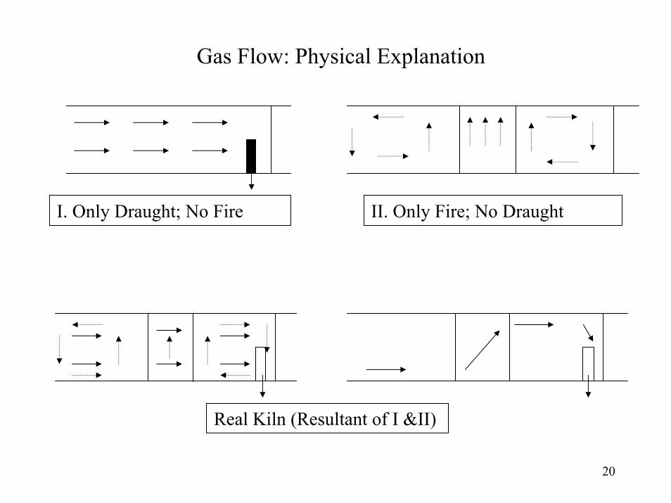
Gas Flow: Physical Explanation
I. Only Draught; No Fire II. Only Fire; No Draught
Real Kiln (Resultant of I &II)

21
1357911131517192123252729313335373941
Top
Bottom0100
200
300
400
500
600
700
800
900
10001100
1000-1100
900-1000
800-900
700-800600-700500-600400-500
300-400200-300100-200
0-100
Coal FeedingBrick
CoolingBrick Preheating
Gas flow in the kiln
Temperature Distribution along the Length of the Kiln
Temperature Distribution

22
Brick temperature distribution and its effect on brick quality
Class I = 66%Class II=12%Class III=12%Class IV=5%

23
Ground ThermocouplesKiln Floor
Duct for carrying extension cable
E
AF
B
D
C
z
z = 0
z =150
z = 1000
z = 4250
Brick soling
41 thermocouples
24
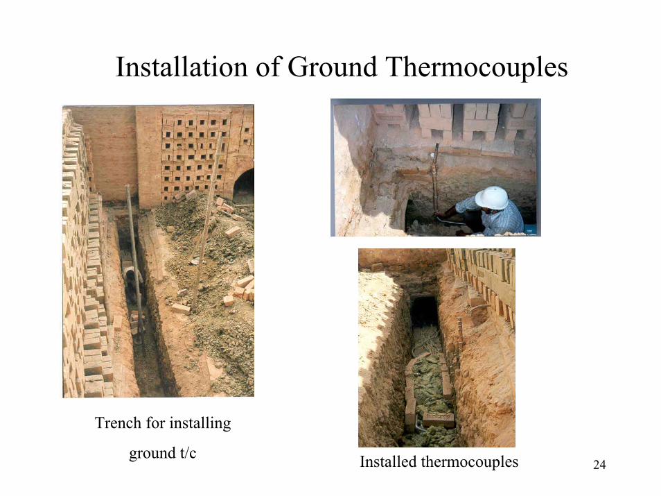
Installation of Ground Thermocouples
Trench for installing
ground t/c Installed thermocouples
25
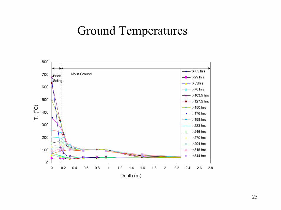
Ground Temperatures
0
100
200
300
400
500
600
700
800
0 0.2 0.4 0.6 0.8 1 1.2 1.4 1.6 1.8 2 2.2 2.4 2.6 2.8
Depth (m)
Tgr (
o C)
t=7.5 hrs
t=29 hrs
t=53hrs
t=78 hrs
t=103.5 hrs
t=127.5 hrs
t=150 hrs
t=176 hrs
t=198 hrs
t=223 hrs
t=246 hrs
t=270 hrs
t=294 hrs
t=315 hrs
t=344 hrs
Brick Soling
Moist Ground
26
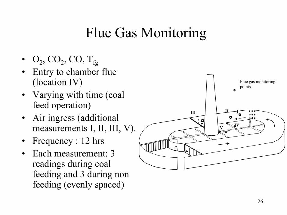
Flue Gas Monitoring
• O2, CO2, CO, Tfg• Entry to chamber flue
(location IV)• Varying with time (coal
feed operation)• Air ingress (additional
measurements I, II, III, V).• Frequency : 12 hrs• Each measurement: 3
readings during coal feeding and 3 during non feeding (evenly spaced)
Flue gas monitoringpoints
IIIIII
IVV

27
Flue Gas Analyzer• O2
– Range (1-25%)– Electrochemical sensor
• CO2– Range (0-20%)– Derived
• CO– 0-10000 ppm– Electrochemical sensor
• Tfg– 0-1000 oC– Type K
Probe, filter, condensate trap, display unit

28
Flue Gas – Typical variation over a coal feeding cycle
0
2
4
6
8
10
12
14
16
18
0 5 10 13 15 17 20
Time (minutes)
YC
O2
, YO
2 ( %
Vol
)
0
500
1000
1500
2000
2500
3000
YC
O (p
pm)
O2 %
CO2 %
CO ppm
Coal Feeding Non Feeding
29
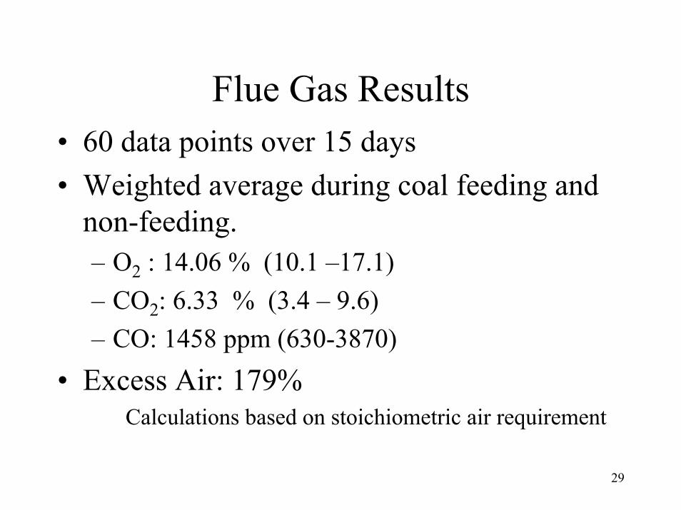
Flue Gas Results• 60 data points over 15 days• Weighted average during coal feeding and
non-feeding.– O2 : 14.06 % (10.1 –17.1)– CO2: 6.33 % (3.4 – 9.6)– CO: 1458 ppm (630-3870)
• Excess Air: 179%Calculations based on stoichiometric air requirement

30
BTK: Mass Balance
Fired brick (79236 kg/day)Green Bricks (86926 kg/day)
Air (78607 kg/day)
Coal (3624 kg/day)
Dry Flue Gas (81506 kg/day)
Water Vapour (16476 kg/day)
Brick Kiln
Ash (725 kg/day)

31
BTK: Energy Balance
Heat in water vapour(Qv =46.5%)
Heat for irreversible reactions(Qr =17.1%)
Ground heat loss(Qgr =12.8%)
Heat loss from the kiln surface (Qsur =14.7%)
Sensible heat loss(Qfg + Qfbr=7.2%)
Misc. & Unaccounted=1.8%
SEC =1.12± 0.03 MJ/kg

32
Uncertainty Analysis• Uncertainties due to least count, instrument
accuracy are relatively small (e.g 2.7% in SEC).• Repeatability : Not possible in plant data (several
external factors – e.g. ambient, production related which are beyond the control of the experimenter; cost factors)
• Large no. of measurements taken over one full firing cycle (15 days) to capture variations in kiln performance and reduce the effect of external factors/happenings on the average values.
• Uncertainty in two calculated energy balance components (Qgr and Qsur) can be significant depending on the assumptions made.

33
Uncertainty Analysis• Qgr
– ‘k’ for brick floor not determined experimentally.– ‘k’ for fired bricks 0.41-0.81 W/m-K [literature]– intermediate value k (T) = 0.41+Tx3.5x10-4 W/m-K was
selected keeping in view low density of bricks.– Higher value of k = 0.81W/m-K would increase Qgr by 44%.
• Qsur– Kiln open to atmosphere; conditions alternate between still air
to windy; difficult to choose a correlation for ‘h’; conservative approach (so that not to overestimate) adopted and natural convection correlation used.
– ± 25% uncertainty in h and ± 10% in ε results in ± 12.5% in Qgr.
– Average ambient temperature (T∞) used in radiation heat loss from kiln roof. Tsky = (T∞ - 6) would result in 9% increase in Qroof.

34
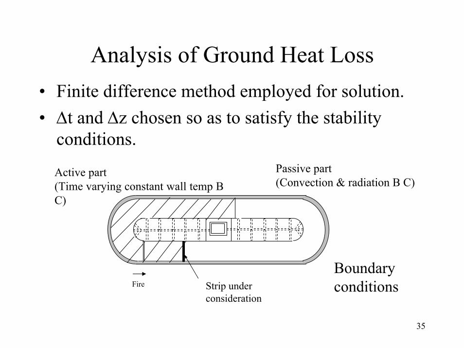
Analysis of Ground Heat Loss• Simple analysis to get a feel for the factors influencing
Qgr• Ground as semi-infinite medium
• 1-D transient heat conduction
tTC
zTk
z p ∂∂
=
∂∂
∂∂ ρ
q gr
z Tgr (z,t)
Kiln floor
Soil
z = 0
z=Lgr Tgr| z=Lgr = T∞
35
Analysis of Ground Heat Loss• Finite difference method employed for solution.• ∆t and ∆z chosen so as to satisfy the stability
conditions.Passive part (Convection & radiation B C)
Active part (Time varying constant wall temp B C)
Fire Strip under consideration
Boundary conditions

36
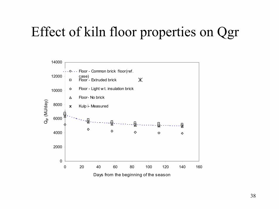
Analysis of Ground Heat Loss• Fair degree of match between the predicted and
measured ground temperatures for Kulpi kiln. Better match possible if moisture transport is also considered.
• Model (under dry soil condition) used to study the effect of:– Ground conditions (different soil densities)– Kiln floor (common brick, extruded, insulation,
unpaved)– Kiln length (167 m, 125 m, 107 m)

37
Effect of ground thermal properties on Qgr
0
2000
4000
6000
8000
10000
12000
14000
16000
18000
0 20 40 60 80 100 120 140 160
Days from the beginning of the season
Qgr (M
J/da
y)
X Measured Kulpi Predicted (ρ=1300 kg/m3) Predicted (ρ=1500 kg/m3) – Reference Case Predicted (ρ=1700 kg/m3) Predicted (ρ=2500 kg/m3)
38
Effect of kiln floor properties on Qgr
0
2000
4000
6000
8000
10000
12000
14000
0 20 40 60 80 100 120 140 160
Days from the beginning of the season
Qgr
(MJ/
day)
Floor - Common brick f loor(ref.case)Floor - Extruded brick
Floor - Light w t. insulation brick
Floor- No brick
Kulp i- Measured
Vertical Shaft Brick Kiln (VSBK)

40
Rationale for studying VSBK• New kiln:
– Chinese origin – Introduced in India in 1996– Reported to be most energy efficient kiln– Suitability for small scale production and for developing
countries requirement • Literature survey:
– One previous study from China NIFES [1993]. No reported Indian study
• Objectives– Energy balance statement – Brick temperature distribution.– Kiln characteristics

41
VSBK- Working Principle

42
VSBK- Brick Setting

43
Brick Temperature Measurement
Fixed Thermocouples
Temperature scanner
Traveling thermocouple
Temperature Recorder
0
Junction welded to
sheath
Mineral Insulation
Termination
Stainless Steel Sheath
Brick with thermocouple in the center of the setting
44
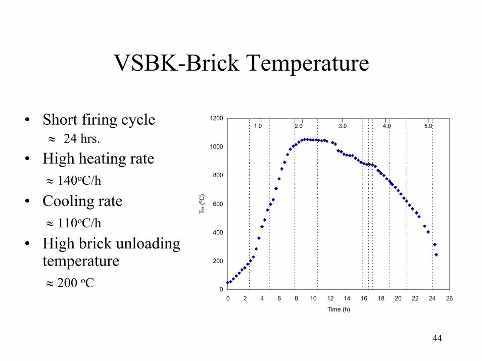
VSBK-Brick Temperature
• Short firing cycle≈ 24 hrs.
• High heating rate ≈ 140oC/h
• Cooling rate≈ 110oC/h
• High brick unloading temperature≈ 200 oC
0
200
400
600
800
1000
1200
0 2 4 6 8 10 12 14 16 18 20 22 24 26
Time (h)
T br (
o C)
1.0 2.0 3.0 4.0 5.0

45
VSBK-Energy Balance
Qv =32.4%
Qr =20.7%
Qfg =15.6%
Qsur =13.8%Qfbr=7.6%
Misc. = 6.4%
Qco
SEC =0.84±0.04 MJ/kg
=3.5 %

46
VSBK – Important Characteristics(Based on data from 16 VSBK studies in India)
• Consistently low SEC (0.76 –1.16 MJ/kg)– Seems to be independent of the production rate
• λ (mair/mbrick) ≈ 1 – ideal value for λ from energy efficiency considerations
• Relatively high CO emissions– 1.16 to 4.38 g/MJ– Typical value for hand fired furnaces = 1.5 g/MJ

47
1-D Heat Transfer and Combustion Model for VSBK: Simplifying Assumptions
• 1- D flow• Counter current heat exchanger• Steady state operation• Coal assumed to move with bricks at same temperature• Gas is assumed to be non-participating in radiation heat
transfer• Momentum equation not solved • Split air flow (20% through side gaps, 80% through
setting)

48
Coal Combustion• Devolatilisation
– Two step mechanism of Kobayashi et al [1976]used to calculate mass rate of volatile generation.
– Volatile composition calculated
• Surface Reactions
• Gas Phase Reactions:4-step quasi global mechanism based on oxidation of CO, C2 H4, H2, CnH 2n+2 used
COCOCCOOC
222
2
2
→+→+

49
Energy conservation for air
• Heat from gas phase reactions accounted in air.• Convective heat exchange between air and inner
shaft wall.• Convective heat exchange between bricks and air
– Re calculated based on superficial velocity
)(100Re5Re04285.0)(exp360Re185Re8432.0
3.0
2249.0
packedbedsSterimentalSt
<<=
<<= −
50
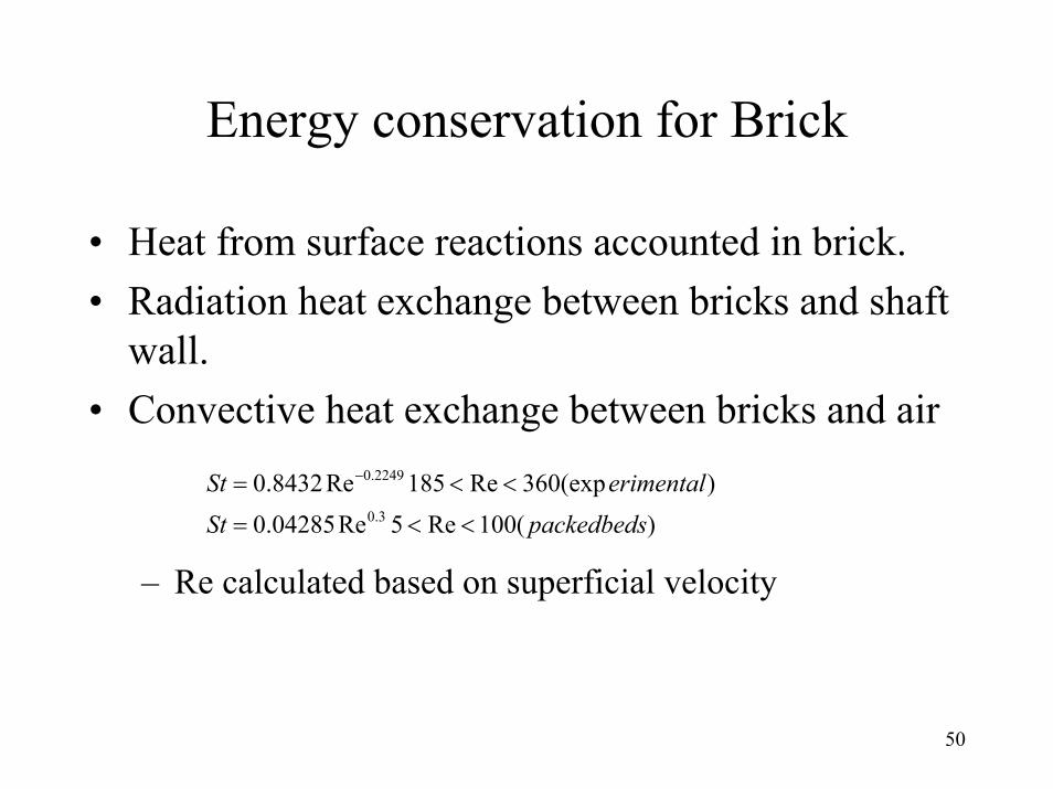
Energy conservation for Brick
• Heat from surface reactions accounted in brick.• Radiation heat exchange between bricks and shaft
wall.• Convective heat exchange between bricks and air
– Re calculated based on superficial velocity
)(100Re5Re04285.0)(exp360Re185Re8432.0
3.0
2249.0
packedbedsSterimentalSt
<<=
<<= −

51
Computational Details•Grid : 1000 grid points
•Gauss-Seidel method
•Convergence criteria: CC max <10-4
nP
nP
nPCC
φφφ 1−−
=
52
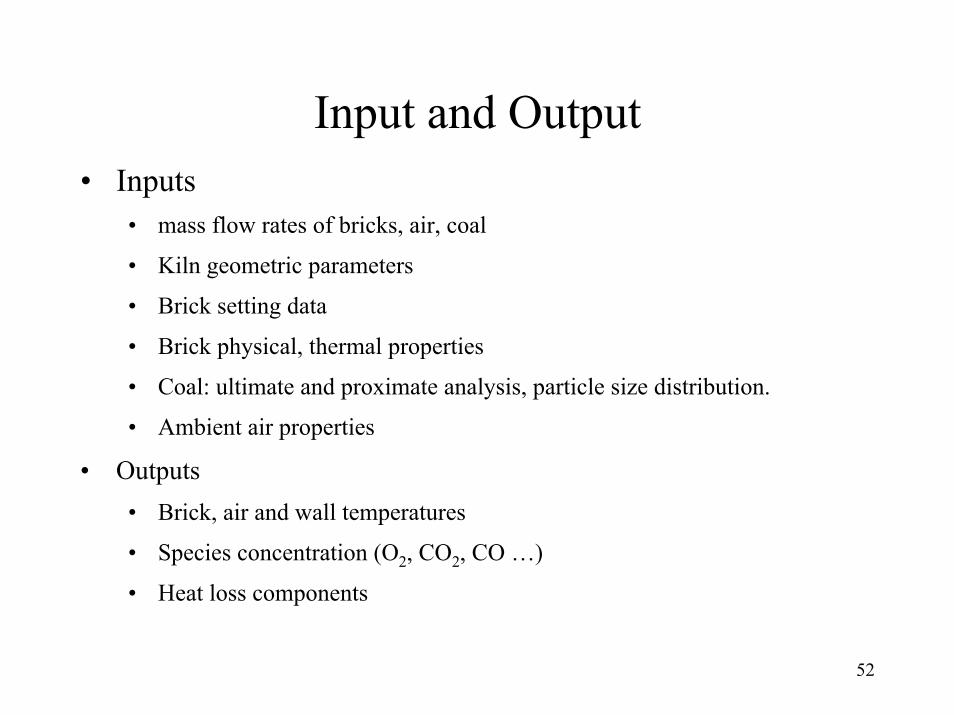
Input and Output• Inputs
• mass flow rates of bricks, air, coal
• Kiln geometric parameters
• Brick setting data
• Brick physical, thermal properties
• Coal: ultimate and proximate analysis, particle size distribution.
• Ambient air properties
• Outputs• Brick, air and wall temperatures
• Species concentration (O2, CO2, CO …)
• Heat loss components

53
Validation of the Model
• For four VSBKs• Fairly good match
– Brick temperatures– Location of the
temperature maxima and maximum temperature
– Exit O2 and CO2 concentrations
0
200
400
600
800
1000
1200
1400
1600
0 1 2 3 4 5 6
X (m)
Tbr,
Ta (K
)
Tbr( Predicted)
Ta (Predicted)
Tbr (Measured)
Ta (Measured)
Brick
Air
Air
Brick
Figure 5.4 Computed and Measured temperatures - VSBK, Varanasi

54
Parametric Study
• Air to brick ratio (λ)• Clay fraction (Xclay)• Kiln throughput (SPR)• Void fraction (φ)• Brick thickness (Bgbr)• Kiln height (Lkiln)

55
Effect of Brick Thickness
0.5
0.55
0.6
0.65
0.7
0.75
0.8
0.85
0.72 0.8 0.88 0.96 1.04 1.12
λ
SE
C (M
J/kg
-bric
k)
Bgbr=52 mm
Bgbr=66 mm
Bgbr=75 mm
Lkiln = 4.5 mφ = 0.36Tbr (max) = 1250 Kmbr = 0.109 kg/sXmbr = 0 .0Xclay = 0.35
56
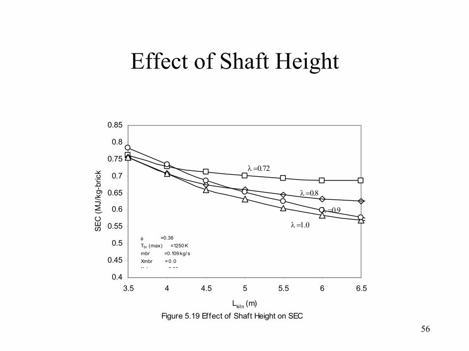
Effect of Shaft Height
0.4
0.45
0.5
0.55
0.6
0.65
0.7
0.75
0.8
0.85
3.5 4 4.5 5 5.5 6 6.5
Lkiln (m)
SEC
(MJ/
kg-b
rick
Figure 5.19 Effect of Shaft Height on SEC
φ = 0.36Tbr (max) = 1250 Kmbr = 0.109 kg/ sXmbr = 0 .0Xclay =0 35
λ =0.72
λ =0.8
λ =0.9
λ =1.0
57
Main Contributions• Development of methodologies and instrumentation
for energy /thermal measurements and analysis for BTK and VSBK.
• Novel features of experimentation– Measurement of ground temperatures (BTK)– Measurement of brick and gas temperatures (BTK)– Measurement of brick temperature using traveling
thermocouple (VSBK)– Measurement of air leakage (BTK)

58
Main Contributions• Development of simple mathematical models for studying
kiln performance and for developing guidelines for energy conservation– 1-D heat transfer model to study ground and roof heat loss
in BTK– 1-D heat transfer and combustion model for VSBK
• Enhanced understanding of BTK and VSBK systems– Mass and energy balance– Temperature distribution– Gas flow

59
Suggestions for future work• Work aimed at development of a new generation
annular moving fire kiln to replace BTK:– Study the effect of different types of brick setting on
heat transfer rates and kiln performance.– Use of low cost insulation materials for brick kiln
construction.– Alternate material for BTK roofing
• Improvements in VSBK– Reducing CO emissions– Improving the chimney systems to reduce emissions at
the top working platform– Alternate materials/equipment/ modifications in design
to reduce construction and operation cost.– Providing better control over firing process