· an energy monitoring and control system (emcs) is an energy management ... (multiplex) for...
TRANSCRIPT

-.. -.
44 I OF7
CR 83-021
NAVAL CIVIL ENGINEERING LABORATORYPort Hueneme, California
Sponsored byCHIEF OF NAVAL MATERIAL
NAVAL FACILITIES ENGINEERING COMMAND
- EMCS OPERATOR TRAINING MANUAL
April 1983
An Investigation Conducted by
NEWCOMB & BOYD, Consulting Engineers*One Northside 75
* )" Atlanta, Georgia
LA.' L N62474-81-C-9405
83 05 13 027.
Approved for public release; distribution unlimited

II
,' ' ' - . C4
p.
E E Jg,
99 _z !29j$tj6t9t
_107 16 I I 1 rl 12 1 L a
I Jog WE 1 --
* 1111 UI il III~ I
UT

-~~ - * . . . . . .
Unclassi fiedSECURITY CLASSIFICATION OF TIlS PAGE (When fl-, Fn-r~d)
READ INSTRUCTIONSREPORT DOCUMENTATION PAGE BEFORE COMPLETING FORMGOOTNMBR~~VT ACCESSION NO. A ECIPIENT'S CATALOG NUMBER
CR 83.021 &PRO OEE.TITLE (and S~bwlI.I S TYPE GF REPORT &PRO OEE
EMCS Operator Training Manual FinalL -e Pp81- l 1982
*PERFORMING ORG REPORT NUMBER
7 AUT OR., B CONTRACT OR GRANT NUMBER(.)
Catherine Cornelius; Billy Wise; and N27-1C90Steven Bruning N27-1C909ERFORMINO ORGANIZATION NAME AND ADDRESS I0 PROGRAM ELEMENT PROJECT. TASKNNWCO & BOYD, Consulting Engineers 6.3; RKUITNMBR
One Northside 75 .3Atlanta, GA 30318 Z0829-01-221D
11 CONTROLLING OFFICE NAME AND ADDRESS 12, REPORT DATE
Naval Civil Engineering Laboratory Ap2ril 1983*Port Hueneme, CA 93043 13NUMBER OF PA'SES
14MONITORING AGENCY NAME A AODRESSP ,I differ,( train COi..infilne 01111.) 15 SECURITY CLASS (of this. tRoorj
Chief of Naval Material, Washington, DCNaval Facilities Engineering Command Unclassified
IO ECLASSIFICATION DOWNGRADINGAlexandria, VA SHDL
IA DISTRIBUTION STATEMENT (.( this Report,
Approved for public release; distribution unlimited
- I? ISTRIUTIONST ATEMEN T (at Ph&. ab.IACI enfI1d in Block 20. $1 different from Report)
IS SUPI EMENTARY NOTES
IS K EY BORDS (Continue on revrse ald. of necessary mid identliI bv block number)
Computer; controls; HVAC; energy; EMCS; operator; training
20 ABSTRAC T (Conitnue on -syts. side It necesary, and idenfII I block nlum.ber)
)This manual is a training aide to accompany the-,,E"Ci Opera- rtor Training Course. It is also intended as a working referencefor the EMCS operator. The manual discusses the basics ofHVAC * ?
* *. sysem operation convering most systems which would be connectedto an EMCS. It includes a generic description of EMCS hardware, 11.0 atexplanations of the energy savings strategies of the EM1 C\
DD I'JOA"7 1473 EDITION OF I NOV SS ISOBSOLETE Unclassified I istbtSEC'URITY CLASSIFICATION OF THIS RAG ama En..qId) on/)
.-aij. 1 1 -
CISla,
*a

.unrlassifiedSE u ITY CLASSIFICATION OF T..S PACE r n D ,e- F-re ,
applications software and discussions of EMCS alarm analysisand system operation.
D O 1473 EDITION 001 1 NOV GS 00OLIFTE UnclassifiedSECURNITY CLASSIFICATION Of Te#IS PAGE Dal. Ew,odI
"°?

EMCS Operator Training ManualTable of Contents
Page
INTRODUCTION i-1
-CHAPTER 1. HVAC SYSTEMS
Section 1. Basics of HVAC Systems 1-1
Section 2. Control Concepts 1-21
Section 3. Configuration and Operation of 1-26
Typical HVAC Systems
Radiator 1-26
Unit Heater 1-31
Fan Coil 1-35
Central Fan Systems 1-38
Single Zone Air Handling Unit 1-41
Terminal Reheat Air Handling Unit 1-43
Multizone Air Handling Unit 1-45
Double Duct Air Handling Unit 1-47
Variable Air Volume Air Handling Unit 1-51
Direct Fired Furnace 1-53
Steam Boiler 1-55
Hot Water Boiler 1-58
Convertors 1-58
Chillers 1-64
CHAPTER 2. ENERGY MONITORING AND CONTROL SYSTEMS
" Section 1. Introduction to EMCS 2-1
Purpose of an EMCS 2-5
EMCS Attachment to the HVAC System 2-5
EMCS Architecture 2-9
Large EMCS Architecture 2-10
V

Computers 2-10
Peripherals 2-12
Field Equipment 2-14
Medium, Small, and Micro EMCS Architecture 2-16
r Section 2. Operator Interaction with the EMCS 2-21
Command Language 2-21
Command Line Mnemonic 2-22
Menu Penetration 2-23
Interactive-Color Graphics 2-25
Operation of the ICG Terminal 2-27
Floppy Disk Drive Operation 2-32
Section 3. EMCS Applications Software 2-34
Scheduled Start/Stop 2-36
Optimum Start/Stop 2-38
Duty Cycling 2-43
Demand Limiting 2-48
Day/Night Setback 2-53
Lighting Control 2-55
Economizer 2-56
Enthalpy 2-60
Ventilation and Recirculation 2-63
Hot Deck/Cold Deck Temperature Reset 2-64
Reheat Coil Reset 2-66
Boiler Optimization 2-68
Remote Boiler Monitoring and Supervision 2-71
Hot Water Outside Air Reset 2-74
Chiller Optimization 2-76
Chiller Water Temperature Reset 2-78
, Condenser Water Temperature Reset 2-80
Chiller Demand Limit 2-82
Applications Software Data 2-83
vi
'a *..
. . . . . . . . . . . . .

i
" CHAPTER 3. SYSTEM OPERATION 3-i
Section 1. Trend Logs and Reports 3-1
f Section 2. Alarms 3-8
Section 3. Optimization of Energy Reports 3-15
Demand Limiting 3-15
Duty Cycling vs. Chiller Water Temperature Reset 3-16
Economizer Control on Double Duct Units 3-20
Optimizing Hot/Cold Deck Reset 3-21
Minimizing Warm-Up/Cool-Down Periods 3-21
Night Flushing 3-21
A Flexible Hot Water Outside Air Reset Schedule 3-22
Boiler Optimization 3-24
APPENDICES
A. Glossary A-1
B. Sample Trend Logs and Reports B-i
vii

I°
INTRODUCTION
This manual was written as a training aid to supplement the EMCS Operator
Training Course classroom lectures. The manual and classroom notes may
also be used as a working reference for the trainee while on duty as an
EMCS operator. The objectives of the EMCS Operator Training Course are to
provide EMCS operators with an understanding of the effective use of an
EMCS as an energy conservation and facility management tool; and to train
them to perform as operators in three functional modes:
1. Normal HVAC operation, including entering parameters for the various
energy conservation routines performed by an EMCS.
2. Recognition and response to alarm conditions occurring in HVAC systems
that are connected to an EMCS on a typical installation.
3. Understanding the concept of fine tuning or "tweaking" the system to
maintain or to maximize energy conservation.
The course is primarily aimed at potential, EMCS operators who have a high
school education and field experience or technical schooling in HVAC or a
related field. For those students who have no HVAC or related experience
or training, an overview of the principles of heating and air conditioning
and the operation of typical HVAC equipment is included in the first
chapter. This will also provide a review for other students.
This course is only the first step in a four phase training program for
EMCS operators. The four phases include:
- EMCS Operating Training Course
- Vendor Training
- Maintenance Shop Rotation
- On-the-Job Training
-i-
. . . . . . . . .. .. . .. . , . .. . . . . . . . . .

The objectives of the EMCS operator training course as described above
include a generic introduction to the EMCS concept as based on the
Tr-Service EMCS Guide Specifications and Technical Manual. The second
phase is Vendor Training, which will provide equipment familiarization and
operating procedures for the computers and energy conservation programs
actually being installed at the site. The third phase is Maintenance Shop
Rotation, which will provide an opportunity for EMCS operator trainees to
see the actual HVAC equipment and controls at the site in operation. The
final phase is on-the-job training, where the trainee will work with an
experienced operator on the EMCS operator console at the site. This
four-phase trianing cycle could be completed in about six months.
An Energy Monitoring and Control System (EMCS) is an energy management
system which employs computer technology to monitor and control equipment
scattered throughout a facility. A central computer supervises operation
and provides the EMCS operator access for entering and retrieving
information from remote control points. Sensors and control devices are
wired into electronic field panels which combine signals (multiplex) for
transmission to the central computer. The central computer automatically
analyzes information received from sensors and initiates control actions
through control devices in the field. In addition to automatic operation,
the central computer provides reports and displays information for the use
of a human operator. Based on this information, the operator can manually
override automatic operations or can adjust parameters used by the
automatic control programs to achieve greater energy conservation or better
quality control. The EMCS may be used to affect energy and manpower
savings, for heating, ventilating, and air conditioning, process equipment,
lighting, chillers and boilers. The EMCS may also be used to assist in
maintenance management. Some EMCS are also used for fire and security
alarm purposes. Fire and security functions have not been generally
implemented on EMCS at military bases, therefore, those capabilities are
not concentrated on in this manual and course.
1-2
*". " - -, * . * ... . . . ..i- I " ' : " • i . . . i

.. . . . ... , . , . . . = . = . . -.. . . , - . . .. r ,-r - . - ..
The systems which have evolved to become modern EMCS were originally
developed during the 1960's, primarily as maintenance and alarm recording
tools. With the Arab oil embargo of 1973, the importance of energy
conservation was brought to the forefront. Spiralling fuel costs since
that time have brought ever increasing pressure on all segments of society
to conserve energy. As this occurred, the capabilities of an EMCS type
m system to conserve energy became the primary focus of their ongoing
development process. Within the government sector, President Carter's
. Executive Order 12003 mandated a 20% reduction in energy consumption by
" 1985 compared to 1975 consumption. Within the military services, this
: resulted in a concentrated program of capital investments to improve the
energy efficiency of military facilities. This program was titled The
Energy Conservation Investment Program (ECIP). The ECIP program has been
used to fund a wide variety of capital energy improvement projects ranging
from modernized boiler plants, addition of wall insulation, family housing
* units, heat recovery projects, etc. One of the most comon ECIP projects
is the installation of a central computerized control system for each
9 military base. Although the systems have been installed under a wide
variety of names, (Utility Control Systems, Utility Monitoring and Control
Systems, Energy Management Systems, Central Energy Management Systems,
*." etc.) the common terminology used today for these systems is "Energy
Monitcring and Control Systems (EMCS)".
The primary use of EMCS on military facilities has been the monitoring and
control of heating, ventilating, and air conditioning (HVAC) systems.
While there has been some applications of EMCS for lighting control,
electrical distribution control, water and sewer system control, etc.,
these vary from site to site, depending on the operating philosophy and
-. funding availability of a particular military base. Since the majority of
,. EMCS are used for control of HVAC systems, the EMCS Operator Training
" Course will concentrate on the principles and application of typical HVAC
*systems to provide the EMCS opet'tor with a baseline background in the
types of systems he wil h. de" ,,g with on an everyday basis. The course
1-3
....... * -. . . . .

will not deal with specific details on individual pieces of equipment used
in HVAC systems (fans, pumps, etc.), but will primarily concentrate on
those components as they fit into an overall HVAC system, the control of
those systems, and how an EMCS is applied to each of those systems.
The second area of concentration for the EMCS operator course is a general
familiarization with EMCS technology, terminology, and basic operation
principles. The course provides basic definitions of terms the operator
will encounter in dealing with the many different disciplines involved with
an EMCS. These include computer technology, sensor and control technology,
utilities system operation, HVAC system operation and facilities
maintenance operations. In addition to HVAC system concepts and EMC system
concepts, the course will provide training in the application of the EMCS
to HVAC systems to accomplish energy conservation and equipment trouble
diagnosis. It is not possible to obtain an in depth education in such a
wide variety of fields within the course of any training program. This
course only attempts to familiarize operator personnel with some of the
basic concepts and provide him with an overview of the technologies with
which he will deal on a daily basis.
S1-4

- - -
CHAPTER 1
HVAC SYSTEMS
Section 1. BASICS OF HVAC SYSTEMS
The primary purpose of heating, ventilating, and air conditioning (HVAC)
systems is to provide a healthy, comfortable environment for people, and in
some cases equipment. Human comfort is dependent on a number of factors,
including:
1. Air temperatures
2. Temperatures of surrounding surfaces.
3. Air humidity
4. Air motion, and
5. Air freshness
- The American Society of Heating, Refrigerating and Air Conditioning
Engineers (ASHRAE) has performed extensive research into human "comfort
conditions". Figure 1-1 provides an illustration of a "comfort zone" based
on the combination of air temperature and humidity. As can be seen from
the figure, as humidity decreases, comfortable air temperature increases.
L'. 1-1
L •. . . . . . . . . . . . . . . . . . . . . .

RELATIVE WUMJOITY
MMID
80%
701
"1 _ SLIGHT COMFORT SLIGHTLYCOOL ZONE W
301
20%I -DRY66 70 74 78 82 86
AIR TEMPERATURE (*F)
EXPERIMENTALLY DETERMINED COMFORT ZONE
Figure 1-1
Thus, 78° air temperature with 25% relative humidity "feels" comfortable to
a building occupant while 780 with a relative humidity of 70% will be
uncomfortable. Therefore, HVAC systems must address both air temperature
" and humidity to maintain comfort conditions. The comfort of a space can be
affected by heating or cooling the space, humidifying or dehumidifying airwithin the space, ventilating (introduction of fresh outside air) and
filtering of the air in that space. These are the basic processes
accomplished by an HVAC system. Note that governing criteria (DOD, local
or service wide) may dictate design or operation outside the Figure 1-1
zone for energy conservation purposes.
1-2
In order to maintain a space at any given temperature, there must be no net
* gain or loss of energy in that space. When energy is transferred out of a
. space, it is called a heat loss. When energy is transferred into a space,
it is called a heat gain. HVAC systems are designed to exactly offset heat
gains or heat losses resulting from external or internal factors. Thus the
amount of heating to be provided by an HVAC system (the heating load) must
equal the net heat loss from the spaces served by that HVAC system. If the
spaces served by an HVAC system have a net heat gain, then that equivalent
amount of energy must be removed by the HVAC system by cooling the space
*- (the cooling load).
Heat gains and losses are a result of heat transfer through the building
exterior envelope (walls, roofs, doors, windows, etc.), internal heat
gains, and transfer of outside air into the conditioned space. Building
envelope loads result from conduction heat transfer and solar heat gain.
Conduction heat transfer is caused by a temperature difference between the
space inside and the air outside. The greater the difference between the
inside and outside temperatures, the more heat is transferred. If the
outside temperature is greater than the inside temperature, heat energy is
transferred into the space. If the inside temperature is warmer than the
outside temperature, heat is lost from the space. In addition to the
amount of temperature differential, the construction of the wall, roof or
window through which heat is being conducted, also effects the amount of
energy transferred between the inside and outside. A measure of the
tendency for a wall or other structure to resist the flow of heat is it's
thermal resistance. Insulated walls conduct less heat than uninsulated
walls, because the addition of the insulation material increases the
thermal resistance of that wall.
In addition to conduction, heat may be transferred into a space as a result
of solar heat gain. This can be due to the sun striking an opaque surface
of a room, such as a wall and heating that wall to a temperature that is
higher than the room temperature. Solar heat gain can also result directly
1-3

* (i
WUTIMI
, M4,
SOURCES OF HEAT GAINS AND LOSSES
Figure 1-2
from sunlight passing through a translucent or transparent surface such as
a window, striking objects within the room, and warming them to a
temperature warmer than the space temperature.
In addition to the building envelope loads, internal heat gains can also
contribute to cooling loads. Any time an object within a space has ahigher temperature than the space itself, it results in a transfer of heat
1-4
i _~.- . ........-..- : .. =':....... ...

m 4 _ -- m .- . w , : . . . . . . L-. - -. -- -- - -- - -
from that object into the space. That heat must be removed by the air. conditioning system in order to maintain the space temperature. People,
.* lights, office equipment and other appliances in rooms have higher
temperatures than the space itself. Thus, all of these objects provide an
internal heat gain to a space. The heat gain as a result of this
* temperature difference is called "sensible" heat gain. "Dry bulb
* temperature" is a measure of the sensible heat content of a substance as
measured by a conventional thermometer.
*" In addition to sensible heat gains, a second type of heat gain must be
" - _considered in air conditioning applications. As illustrated on the comfort
condition chart, human comfort is related to the humidity within a space.
- Any increase of space humidity due to addition of moisture to the air in
-. the space contributes to the "latent" heat gain and must be removed by the
*air conditioning system in order to maintain the space's humidity.
. Moisture evaporating from the surface of people's skin is one source of
* latent heat gain in a space. Appliances such as kitchen equipment which
* result in evaporation of water or moisture into the air also add a latent
heat gain to space.
In addition to building envelope and internal heat gains, heating or
cooling loads may result from the introduction of outside air into a space.
. Outside air may enter a space through cracks around windows or doors or
from opening and closing of doors or other openings in the exterior
building skin. This addition of outside air is called "infiltration". If
the outside air introduced by infiltration is at a different temperature
than the space temperature, it adds a sensible heating or cooling load to
the space. If the outside air contains more moisture than the room air, itadds a latent cooling load to the space. In addition to infiltration,
outside air must be added to the space by the HVAC system for ventilation
purposes. Ventilation air also can add heating or cooling loads on the
HVAC system if it is not the same temperature and humidity as that being
maintained in the space.
1-5

"F -- - - - " -' - ." . -. . -. - -' . . . . . . . .. . . . . . .. . . , . . . . -
The actual heating or cooling load within a space is equal to the sum of
all individual heat gains and heat losses to that space. During most of
the time, spaces have both heat gains and heat losses. For example, when
the outside temperature is cold, heat losses occur through walls and
windows while at the same time, people and lights within that space provide
heat gains. If heat losses are exactly equal to heat gains, then no net
heating or cooling load occurs in the space. If the total of heat losses
is greater than the total of heat gains, then the difference between the
two is equal to a heating load (i.e. HVAC must add heat to the space).
They may have a net heating or cooling load depending on a wide variety of
factors, including outside air temperature, solar heat gain and internal
loads.
Groups of spaces along the exterior of the building are normally referred
to as perimeter zones, and are the most influenced by exterior conditions.
Spaces within the building, which are not adjacent to any exterior surface
of the building, are called interior zones. Interior zones generally
require cooling even during the winter because internal gains from lights,
people and equipment are not offset by losses through exterior surfaces.
This requirement for cooling in interior zones while perimeter zones may
require heating adds complexity to HVAC systems. The HVAC system of a
building must be able to provide cooling to interior spaces at the same
time it provides heating to perimeter zones. The wide variety of HVAC
systems which will be discussed later in the course is in large part due to
this requirement.
L1 Every building that is heated, requires some means for converting raw
energy into heat (thermal energy). The source of energy may include fossil
" fuels, wood, sunlight, purchased steam, electricity or waste heat recovered
* from refrigeration machinery or other processes. The function of the HVAC
i 4equipment is to effectively convert the specific form of energy to heat and
transfer this heat from the source to the conditioned space. The amount of
heat transferred is usually designated as a rate of flow in BTU per hour.
" 1-6
A" " i,, ,W~ ' ' i . , , • . . .... .

INTERIOR ZONES
COOLING YEAR-ROUND
PERIMETER ZONESHEATING AND COOLING
Figure 1-3
A BTU or British Thermal Unit is the amount of heat that must be added to* one pound of water to raise its temperature one degree Fahrenheit.
Some equipment is designed to radiate heat into a space: wood-burning
stoves, electric heat strips, and radiators. Other equipment is designed
to transfer heat to a moving stream of air which is circulated through thespace to be heated: direct-fired furnaces, unit heaters, fan coils, andcentral air distribution systems. The heat from combustion of fuel orother heat source may be transferred directly to the air stream as in a
1-7
. **"

direct-fired furnace or air solar collector. In other systems water is
heated at a central boiler, heat recovery unit, or solar collector panels
and distributed to the fan units. The fan blows or draws air across either
a steam or hot water heating coil installed inside a duct. A coil is made
of many feet of twisted finned tubing through which the hot water or steam
flows. The heat transfer capacity of the coil is varied by varying the
flow rate of water or steam through it with a control valve.
If the energy source being used is electricity, then the energy conversion
process is accomplished by means of some type of electrical resistance
coil. The wires or elements of a coil have a resistance to the electricity
flowing through them. The electrical current flowing through this
resistance results in heating of the coil surfaces. That heat is then
transferred to the medium which is to be heated. Electric heat may be used
directly to heat room air as is the case with electric baseboard heat or it
may be used in an electric duct heater to control supply air temperature
which is then transferred to the room to be heated. Electric heat may also
be used to heat hot water which may then be transferred to heating coils or
radiators to provide heat for the building.
A variety of combustible fuels are used in building heating applications.
These include coal, natural gas, propane gas, light oil (#2), heavy oil
(#6) or combinations of these fuels. In all of these cases, the process
used to obtain heat is that of combustion. The fuels are burned at a high
temperature adn the heat given off in the combustion process is then
transferred to the building or space to be heated.
During the heating season humidification of heated air may be desirable.
In spite of the addition of moisture to the inside environment by the
presence of people, the relative humidity can decrease to an uncomfortable
level due to infiltration and ventilation with outside air. By definition,
relative humidity is the ratio of the amount of water vapor in a sample of
1-8

.
air under study to the maximum amount of water vapor which could be in that
air at the same temperature without condensing. Warm air can hold a larger
amount of water vapor than cool air. Therefore, when air is heated without
U the addition of moisture, the relative humidity decreases. For example,
outside air at 35OF and 40% relative humidity heated to 68°F will have aresultant humidity of 11%. The most common method for humidifying supply
air is by steam injection as shown in Figure 1-4.
OA
STEAM
IA>FA
HEATING COIL
STEAM INJECTION HUMIDICATION
Figure 1-4
1-9

,-I
T.
.WATER"DISTRIUTiOR". SYSTEN
ELCIC NTOR1
AV RC
TYPCALEVAORTIV COLE
Figure 1-5
- Heat gains must be compensated by removal of heat from the conditioned
space. This is accomplished by passing an air stream through a cooling
• , coil or evaporative cooler. A typical evaporative cooler is shown in
* Figure 1-5. Three sides of the metal housing is covered with a porous
-. material that is kept saturated with water. A small pump circulates water
: from the basin up and over the porous material. A float valve in the basin
* regulates the flow of make-up water that replaces water which evaporates
*and Is carried off by the air stream. Heat is required for the
* vaporization of the water and is supplied by the sensible heat of the air
1-10
MO

F.-
resulting in a lower dry bulb temperature. As a result of the process,
however, the humidity and thus the latent heat of the air increases. This
method of cooling is only feasible in arid climates such as the Southwest
states.
* Cooling coils are capable of removing latent heat as well as sensible heat
from an air stream, thus performing the dehumidification function. The
temperature of the coil must b below the dewpoint of the air stream, the
temperature at which water will condense out of a sample of air. This
temperature varies depending on the amount of moisture in the air. Thus, as
the air passes over the coil moisture will condense on the cold tubes.
Cooling coils may be either chilled water coils or direct expansion (DX)
-coils. As with hot water heating coils chilled water is pumped throughout
-* a building to the chilled water coils from a central chilled water plant.
The chilled water is generated by a vapor compression refrigeration cycle
* or absorption refrigeration process in the central plant chillers.-" Refrigerant is the cooling medium flowing through a DX coil, which is an
S"integral part of a vapor compression cycle.
.' The vapor compression refrigeration process is based on the fact that the
temperature at which a liquid boils varies proportionally with the-" pressure. For example, water at atmospheric pressure boils at 212 0F. The
same water in a closed container, such as a pressure cooker, at 15 psig (15
pounds per square inch above atmospheric pressure) boils at 250*F. Thus,
by changing the pressure in a closed system it is possible to condense a
gas at one temperature and vaporize the same substance at a lower
temperature. Cooling, that is heat removal, from the surroundings is
achieved when a liquid boils or vaporizes at a temperature lower than the
surroundings. Thus, certain substances are used in refrigerating systems
which under controlled pressures will boil at the desired temperatures.
Many substances have been used as refrigerants, but the most common used
1-11

today in air conditioning systems are fluorinated hydrocarbons. They are
composed of carbon, hydrogen, chlorine, and fluorine in different
proportions, and are non-corrosive, non-flammnable, non-toxic,non-explosive, clear water-white, and have a slightly sweet odor.
Refrlgerant-12 and Refrigerant-22 are good refrigerants for air
conditioning. The boiling temperatures corresponding to various pressures
are listed in Table 1 for Refrigerant-12 and Refrigerant-22.
1-12

Table 1Properties of Saturated Refrigerants
R-12 R-22Temp. Press. Ht. of Vap. Press. Ht. of Vap.OF psia BTU/Ib psia BTU/lb
-40 9.3076 72.913 15.222 100.257
-30 11.999 71.903 19.573 98.801
- -20 15.267 70.874 24.845 97.285
-10 19.189 69.824 31.162 95.704
0 23.849 68.750 38.457 94.056
10 29.335 67.651 47.464 92.338
20 35.736 66.522 57.727 90.545
30 43.148 65.361 69.591 88.674
40 51.667 64.163 83.206 86.720
50 61.394 62.926 98.727 84.678
60 72.433 61.643 116.31 82.540
70 84.888 60.309 136.12 80.298
80 98.870 58.917 158.33 77.943
90 114.49 57.461 183.09 75.461
100 131.86 55.929 210.60 72.838
110 151.11 54.313 241.04 70.052
120 172.35 52.597 274.60 67.077
130 195.71 50.768 311.50 63.877
140 221.32 48.805 351.94 60.403
150 249.31 46.684 396.19 56.585
1-13

Also listed is the heat of vaporization per pound of refrigerant
corresponding to the temperature/pressure states shown. The heat of
vaporization is the amount of heat which a substance absorbs when it
vaporizes. Pressure is listed in units of pounds per square inch absolute.
Note that Refrigerant-12 boils at -21.6*F and Refrigerant-22 boils at
-41.40F at atmospheric pressure (14.7 psia); therefore, they are both gases
at atmospheric conditions. Refrlgerant-22 was originally developed for low
temperature applications. It also provides a greater cooling capacity for
the same size equipment, as indicated by the larger heats of vaporization
at given pressures. It is not recommended, however, that refrigerant in a
system be changed without approval of the compressor manufacturer.
A schematic of the vapor compression refrigerant cycle is shown in Figure
1-6. The cycle consists of four basic processes. In one process the
pressure and temperature of gaseous refrigerant is increased by the action
of the compressor. The compressor can be thought of as a pump for gases,
and serves the function of pushing the refrigerant through the balance of
the cycle. In the next process heat is rejected from the refrigerant and
it condenses to a liquid in a heat exchanger aptly called the condenser.
Next, the liquid refrigerant is allowed to expand through an automatic
throttling device (expansion valve) which is actuated by temperature and
pressure. At the lower pressure resulting from the expansion process the
liquid vaporizes in a heat exchanger called the evaporator, absorbing heat
as It does so. The higher pressure in the system is referred to as either
the condenser pressure or head pressure. The lower pressure is referred to
as the evaporator pressure or suction pressure.
The capability of refrigeration equipment to cool is usually expressed in
tons. The term dates from the era before mechanical refrigeration, when
ice was used for refrigeration. A ton of ice melting in 24 hours will
absorb heat at the rate of 12,000 BTU per hour. Thus, in the field of
mechanical refrigeration, a heat removal capacity of 12,000 BTU/hr is
referred to as one ton of refrigeration.
1-14
:ah.-.

.-o
CONDENSER
HIGH PRESSURE"--REFRIGERANT---- R EFRIGERANT GAS~LIQUID
: - EXPANSIONVALVE COMPRESSOR
LOW PRESSUREiREFRIGERANT GAS
EVAPORATOR
REFRIGERATION CYCLE
Figure 1-6
Vapor compression refrigeration machines generally use one of two types of
compressors: reciprocating or centrifugal. The reciprocating compressor
is comparable to an internal combustion engine in some respects, made up of
pistons, all attached to the same rotating shaft and moving up and down in
cylinders. On the intake stroke of the piston, a quantity of refrigerant
gas fills the cylinder. On the compression stroke, the refrigerant is
compressed and discharged from the cylinder. Refrigeration applications up
i 1-15

ADJUSTABLE INLET GUIDE VANE FOR CAPACITYCONTROL OF CENTRIFUGAL COMPRESSOR
Figure 1-7
to 60 tons generally use reciprocating compressors. From 60 to 200 tons,either reciprocating or centrifugal compressors may be found in use. Above
200 tons normially centrifugal compressors are used.
Centrifugal refrigeration machines were developed to fill the- need forsingle refrigeration units of large capacity. The operating member of acentrifugal compressor is the impeller. The center of the impeller isfitted with vanes that draw gas into the rotating impeller body. Impeller
rotation accelerates the refrigerant gas. As the gas flows through thecomfpressor passages the kinetic energy, or energy of motion, is convertedto static energy or pressure. A centrifugal compressor is suited for awide range of cooling loads. The cooling capacity is varied by adjusting
the position of inlet vanes located ahead of the impeller. Vane position
affects the entering gas quantity as well as the angle at which gas enters
the impeller.
1-16

,' ..'" ." .- " "". " " ' -. . " : " ' '
td,
,' IMFRIGERANT
TARVAPOR
€D~NMF ONCENTRATOR OO~lS
S ISOLUTION CONDESER WATER
FW IOEATA TIO REFRIGERANTO VAPOS
"" MSORI[R APORATOR
ABORE C. VAITR CONDITIONIN
•N VrW SOLUTION PUMqPS REFrRIGERANIT PUMPS
FLOW DIAGRAM OF ABSORPTION REFRIGERATION SYSTEM
Figure 1-8
Absorption refrigeration machines are based on the two facts: that water
* has a low boiling point in a vacuum, and that salt has a high affinity for
-: water. Figure 1-8 is a flow diagram of an absorption refrigeration system.
;! Usually the refrigerant in the absorption cooling process is distilled
* water and the absorbing solution Is lithuim bromide salt dissolved in
,. water. The four chambers are generally located within one shell which is
1-17

- -.-.- .- , -
purged of air. The heat exchanger and pumps are external to the shell.
. The evaporator and absorber are at a pressure 1/100 that of atmospheric
pressure. The concentrator and condenser are at a higher pressure, which
* . is still about 1/10 that of atmospheric pressure.
In the concentrator refrigerant is boiled from the dilute solution at about
210*F. Heat is supplied from a steam or hot water coil immersed in the
solution. The refrigerant vapor migrates to the condenser leaving behind a
concentrated solution which returns to the absorber. In the condenser the
vapor is condensed at about 1120 on the surfaces of the condenser tube
bundle which carries cooler cohdensing water. The liquid refrigerant is
expanded through an orifice to the lower pressure evaporator. The instant
evaporation or flashing of some of the liquid cools the remainder to aboiling temperature of about 400F. The refrigerant is circulated from the
bottom of the evaporator chamber and sprayed over the evaporator tube
bundle. As the liquid evaporates it cools the water which flows through
the tubes and back out to air conditioning cooling coils. The evaporated
refrigerant vapor migrates to the absorber section where it is absorbed by
the concentrated absorbing solution. The heat released in this process is
rejected to condensing water. The diluted solution is then pumped back to
the concentrator.
Absorption machines were developed for large capacity use before the advent
of the centrifugal chillers. Absorption equipment is highly inefficient
having efficiencies of only 20 to 30 percent. As a result, their use has
declined except in buildings that have waste steam or excess steam
available. Absorption refrigeration can be useful as a back up to
centrifugal equipment in situations where it is crucial to hold down the
electrical power use.
-- Besides heating, cooling, humidifying, and dehumidifying, HVAC equipment
provides good interior air quality. The American Society of Heating,
* 1-18

I' Refrigerating and Air-Conditioning Engineers, Inc. (ASHRAE) has established
standards for air quality. City codes also frequently specify the amount
of outside air that must be brought into a space. The process of supplying
and removing air by natural or mechanical means to or from a space is
termed ventilation. The purpose of ventilation is to replenish oxygen in a
building and remove air that has been contaminated. Most fan systems are
designed to bring in a certain amount of outside air. The amount of fresh
air required is dependent on "the function of the interior space. For
example, a chemical laboratory may require that 100% of the air supplied to
the lab be brought in from outside to replace the interior air contaminated
- by chemical fumes. An office building may require as little as 10% of the
supply air be brought in from outside, the remainder being recirculated
-* air. Table 2 lists a sampling of ventilation requirements as recommended
by ASHRAE. Note that Department of Defense or local codes may vary
considerably from the requirements listed in Table 2 and that the
applicable code or guidance for a particular facility should be used for
that facility.
Table 2
Outdoor Air Requirements for Ventilation
Smoking Non-smoking
Cafeterias 35 7 cfm/personHotel bedrooms 30 15 cfm/roomHotel lobbies 15 5 cfm/personOffice space 20 5 cfm/pefsonPet shops 1 1 cfm/ftHospital operating rooms - 40 cfm/personAuditorium 35 7 cfm/person
HVAC fan systems also control air purity by reducing or eliminating
unwanted particulate or gaseous matter from the air supplied to a space.
1-19

This is accomplished by placement of filters in the air streams. There are
many types of filters which vary in the degree of efficiency. Normal
applications are generally concerned with removal of only particulate
matter. Laboratory "clean rooms" require very high efficiency filters
which will remove a major percentage of very small particles. Other
applications require filters capable of elimi'nating odors, viruses, and
bacteria.
Ventilation and filtering affect the energy consumption of HVAC equipment.
Outside air which is introduced to a building needs to be heated and cooled
contributing to the heating and air conditioning load. Therefore, it
should be kept at a minimum, within recommended limits, most of the time.
Filters are an obstacle to the flow of air in an air handler adding to the
horsepower requirements of the system fans. More efficient filters result
in greater pressure loss and the need for larger 'fans. So high efficiency
filters should only be installed where the function of the conditioned
space requires it. Dirty filters result in greater load on existing fans
and cut down on the actual volume of air delivered to a space. To maintain
greater system energy efficiency as well as filtering efficiency filters
should be cleaned or replaced regularly.
1-20

SECTION 2. CONTROL CONCEPTS
Most HVAC systems have some kind of automatic control system, often
referred to as a local control loop, which at least controls the operation
based on a room thermostat if not much more. The primary components for
the automatic control systems are sensors, controllers, and actuators. The
sensor senses changes in a variable, and sends a signal to a controllerindicating a change has taken place. The controller receives that signal,
interprets it, and takes an action based on the sensed input and the
"HETIN COIL
MIXED AIR__TO SPACE
(0i-.. . SPACE
HEATING COIL CONTROL
Figure 1-9
1-21

controller settings. The output of the controller signals an actuator
which effects some change on a component of the HVAC system.
As an example of a control system consider a person driving an automobile.
The sensor is the eyes which note the changes in the curve of the road.
The brain is the controller which interprets what the eyes see and decides
what corrective action needs to be taken to keep the car on the road. The
hands are the actuator which respond to the brain's signals and adjust the
steering wheel to maneuver the car which is the controlled system.
The typical control situation in an HVAC system is a thermostatically
controlled hot water valve on a heating coil, illustrated in Figure 1-9.
The room thermostat is the controller which also houses the sensor that
senses air temperature. The valve actuator positions the valve to limitthe amount of hot water flow through the coil.
There are two primary types of measurement and control used in HVAC
applications: two position and modulating (proportional). Two position
control devices designate one of two operational modes, such as on/off or
open/closed. Two position measurement sensors detect if the equipment is
on or off, open or closed. Two position type measurement also can be used
to sense whether a measured variable is above or below a set value. For
I example, a freezestat can detect whether or not a temperature is above
40*F, and as a result opens or closes electrical contacts in a circuit.
Likewise a differential pressure switch interrupts or completes an electric
circuit if the difference in pressure between two pressure sensors is above
or below a set value. A flow switch responds the same to flow of a liquid.
Modulating or proportional control devices set an actuator or motor at any
position between on or off (open or closed). For example, a modulating
control device may be used to position a valve to regulate the flow of
water. As the valve position varies from open to closed the flow rate of
1-22

- - - - - - - - - --.- . - .
I
I
water varies from full flow to no flow. Proportional measurement produces
a signal whose value is related to the value of a real physical parameter.
For example, a temperature sensor produces a output signal which is
proportional to the temperature it is measuring. Such devices generally
have a limited range over which they operate. For example, a temperature
sensor designed to measure room temperature would be reasonably accurate
over the range of 500 to 1000F, but would not be accurate for measuringboiler stack gas temperatures on the order of 10000F.
P~vUT ,-SPAIN
FLAPPER
SEn=C ATIOU
iD
AJTAK[
SUPPLY AlR N...~9?OL AIRINPUT (MAIN)
SIMPLE PNEUMATIC CONTROLLER
Figure 1-10
'i 1-23
2"." . .-i.. - ." :.. - '. • ' - " ' ': '- T,- 'I~l m - ' ' , ' ' " - ' - n' ' ' ' ' '%c

Another element which is necessary for automatic control is a source of
power to supply energy to the actuator and for the transmission of signals.
This power supply can be either pneumatic or electric/electronic. Both two
position and modulating control systems can be constructed using either
pneumatic or electrical control devices.
Pneumatic controls are powered by compressed air, usually 15 to 20 psig
pressure, although higher pressures are occasionally used for operating
very large valves or dampers. Pneumatic devices are inherently modulating,
since air pressure may easily be provided with infinite variation over the
control range. Because of their simplicity and low cost, pneumatic
controls are frequently found on commercial and industrial installations
using more than eight or ten devices.
Pneumatic devices available include sensors, controllers, actuators,
relays, and transducers. A relay is a two position switch. Transducers
are devices which can convert a variable output electrical voltage to a
varying air pressure or vice versa. Relays and transducers may be used to
interface pneumatic and electric devices or control systems. For example,
a pneumatic/electric (PE) relay is an electric switch which opens or closes
in response to a pressure signal. An electric/pneumatic (EP) relay is a
solenoid air valve which is opened or closed based on the status of the
electrical circuit to which it is connected.
Electric controls are available in a wide variety of configurations for
every conceivable purpose in HVAC application. All of these are based on
one of four operating principles: The switch, the electromagnetic coil and
solenoid, the two position motor, and the modulating motor.
Any electrical circuit includes three elements: a power source, a switch,
and a load. The load represents resistance and consumes the power. The
switch serves to turn the power on and off. In an HVAC system, the load
will be an actuator or relay, the switch will be sensor-controller. The
1-24

IL
power source is usually the building's electrical power which may be used
at a normal 120 volts or transformed to some lower voltage, typically 24
volts. Some electrical devices use direct current (DC). This may be
supplied by a battery or an alternating current (AC) source by means of a
. transformer and rectifier.
In addition to classifying controls as two position or modulating and
pneumatic or electric, a new classification is evolving with the
. integration of computer technology into control systems. This
" classification is analog versus digital type control systems. In the past,
* most control systems have been analog systems where signals within the
*control system varied continuously in some physical manner related to the
, control system activity and control logic was implemented by means of
relays, controllers, actuators, and other physical devices. Digital
control systems, which are becoming more common, use micro computers to
perform control logic functions and computations. Sensor and control
signals are transmitted in the form of digitally encoded data rather than
continuous varying signals.
1-25
* ,-* . . . . .

SECTION 3. CONFIGURATION AND OPERATION OF TYPICAL HVAC SYSTEMS
There are a wide variety of HVAC systems used to provide heating and
cooling to buildings, in fact almost every building/HVAC system combination
is unique in its implementation and operation. In this section, a general
description of the most commonly used HVAC systems will be provided,
however, it should be understood that at a particular installation the
actual implementation and operation of HVAC systems may vary considerably
from what is described herein. However, the basic concepts and terminology
should give *the EMCS operator a overview of HVAC systems and their
functions.
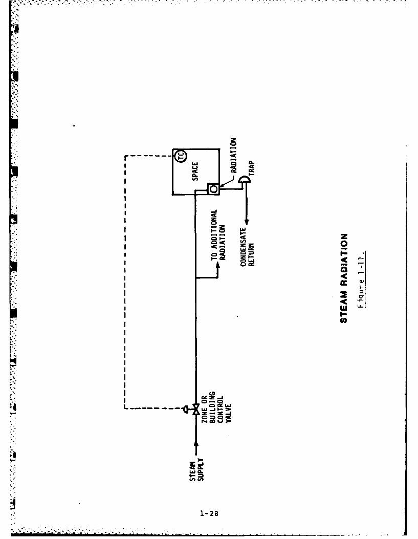
Radiator
The simplest type of HVAC equipment is the radiator. It only provides
heating. Heat is transferred to the air, people and objects in the room by
radiation and natural convection from the hot surfaces of the radiator.
Natural convection is the process by which heat is transferred between a
solid surface and a fluid (liquid or gas) which moves across it as a result
of the temperature difference. The heating medium in radiators is steam,
hot water, or electricity.
A radiator may be automatically or manually controlled. Automatic control
is achieved by thermostatic control of a steam valve at each radiator.
Usually a self contained thermostat/valve combination is used for that
purpose. In addition to individual room control, entire radiator systems
may be controlled based on the outside air temperature. If the outside air
temperature is above a certain setpoint, the pump (for hot water systems)
or main steam valve (for steam systems) may be turned off or closed. In
addition, for hot water systems the temperature of the water supplied to
1-26
pA

•- .- . - ..-. " - ..
the radiators may be varied depending on outside air temperature. For
example, if the outside air temperature is 600 the water supplied to the
radiators may be set at 100, while if the outside air temperature is 00,
the hot water temperature may be set at 2000.
1
1-2
-. -. - - . -~- --- --. - - m ~ -* - . . - -- , c
.- Ac
CLa
-8 I-

I z
I 0 j
r4.
i La
j 0.
1-9

4Kzz
... JL&B..J
; O-
~JL&J
CS&
I-
1-30
- iJ

* . . :i? . - .-- .- * - _.., -. . -... .i.. ,- .- -- . - . .. . . .
Most radiation systems are not properly controlled. As a result, they can
waste energy and easily overheat a space. If the occupants of the space
have no other means of control, they usually open the windows to maintain
the space at a reasonable temperature. This obviously is an extreme waste
of energy, a result of the inability of the control system to do its job.
A convector is a variation of the radiator, designed to transfer heat to
the space primarily through convection. Convectors have specially designed
enclosures to promote free air flow through a coil or other heat transfer
surface. The same types of control used for radiators are used for
convectors.
Unit Heater
Another type of heating only device is called a unit heater. A unit heater
is basically a radiator or convector with a fan added to the system. A
unit heater may be steam, electric, or hot water type and may be controlled
using the methods described for radiation systems. In addition, control
may be accomplished by cycling the unit heater fan in response to a room
thermostat. However, an additional control mechanism must be provided to
prevent the unit heater fan from operating when a heat source is not
available (i.e. when the steam supply to the building has been turned off).
*. This may be accomplished through wiring interlocks or by an aquastat
attached to the piping supplying the unit heater coil. The aquastat senses
the temperature of the piping and if it is below a set temperature
(indicating the heat source has been turned off) it will not allow the unit
heater fan to run, even though the thermostat In the room calls for
heating. This prevents the fan from circulating cold air, which would
cause further discomfort to the room occupants. While the unit heater is
still a heating only system, It has greater flexibility than radiators and
convectors in that It can more widely distribute the heat within the space
it serves.
1-31

CieI.
PAA
CD I.- -
I.--a
(.J.
w
44
1-32

-AJAJZ
LiJOJ
LIU
LaJUKjLiiU
Lai LhJ
1-3-

a.AJ Ju
0~l
zoo
LuU
=x
U-
0CLa x
-CL. Lai
CL
~~IA
1-34

7. 7
r,'
Fan Coil
Another type of HVAC system similar to the unit heater is called a fan coil
system. Fan coil systems generally provide heating and cooling. A fan
coil unit consists of a small fan and coils mounted within an enclosure.
An individual fan coil unit normally serves a single room and may be
mounted above the ceiling withK a diffuser or register supplying air or on
S.- the floor at an exterior wall. Normally, many fan coil units are connected
*' together by the piping network which carries hot or chilled water from some
".. - central heating or cooling equipment location.
Fan coil systems classified as "two pipe" systems house a single coil which
is used for heating in the wintertime and cooling in the summertime. It is
connected to a single supply pipe and single return pipe. In the summer,
chilled water is circulated in the piping system and in the winter hot
water is circulated in the piping system. A "four pipe" fan coil system
has two separate coils connected to separate chilled water and hot watercirculating systems. Thus, in a four pipe system, heating or cooling may
be chosen by the room thermostat based on the room temperature.
Fan coil system controls generally consist of a thermostat which controls
the action of the fan coil unit. The thermostat may be mounted within the
fan coil unit enclosure or mounted separately on a wall. Some fan coil
control systems allow the fan to run continuously and modulate temperature
by opening or closing chilled or hot water valves serving the fan coil
unit. Other control systems cycle the fan coil unit fan on and off based
on the temperature requirements. In addition to the local controls at each
fan coil unit, a two pipe fan coil system must contain controls which
perform the changeover from circulation of hot water to chilled water when
operation of the syste is changed from heating to cooling and vice versa.
' This changeover control may be accomplished automatically based on outside
air temperature or other parameters, or may be manually accomplished based
on the season of the year.
1-35
../q '* . .* ,.

C.
C.Lz
Lm ~
CL.,
z
L.
z LCL
aLC.
0.L
z
I. I w La
I1--

cr I --- -
2c I - - -- 0 V
cc ;2 z 0
a~~LA 1-lLUi CJ L.)
II.
LaiO ..J 0.LU~LL.
I. LJL~ .. J
* - LUO CieI, ~J ij
LU 11 .- Z -
kL- Jce~
I -
1-3707U

U
Some fan coils have an outside air vent with a manually controlled damper
for bringing in a small amount of fresh air. Individual room units with
more sophisticated automatic damper control of outside air also exist.
These are usually termed unit ventilators.
Central Fan Systems.
Radiators were the most common heating system used in the past. Now fan
coil units are used heavily for specific types of applications (hotels,
motels, dormitories, etc.), but most buildings which would be connected to
an EMCS are provided with heating and cooling through various types of
central fan systems. These systems provide for the distribution and
control of heating and cooling energy to individual spaces within a
building. They may or may not include the primary energy conversion
mechanism for heating or cooling. In general, central fan systems use a
system of ductwork to distribute heated or cooled air from the fan system
location to the spaces it serves. Air is returned from those spaces
through separate ducts or plenum system for recirculation or exhaust. A
central fan system generally serves several areas of a building instead of
only one room. The different types of central fan systems which will be
discussed are:
1. Single zone air handling unit.
2. Terminal reheat air handling unit.
3. Multizone air handling unit.
4. Double duct air handling unit.
5. Variable air volume air handling unit.
In addition to the temperature controls, central air systems normally have
safety controls to prevent damage to the equipment or to provide occupant
safety. Common devices for these purpose are freezestats, firestats, and
4i smoke detectors. A freezestat is normally located on the inlet of heating
or cooling coils which are susceptible to freezing. If the entering air
1-38

temperature to the coils drops below the 350 to 40' temperature range, the
freezestat will automatically shutdown the fan system to prevent freezing
of the coils. In a similar manner, firestats are located within the fan
system such that if they detect a temperature above 125°F they shutdown the
air handling system. Most modern systems also include smoke detectors
within the air handling system and in the occupied spaces which sense the
presence of smoke and shut down the air system, if smoke is detected.
Smoke detectors may also be used to operate central air systems in special
smoke control modes, when the air system is actually used to evacuate smoke
or to pressurize areas adjacent to smoke filled spaces to prevent migration
of smoke into the uncontaminated areas. These smoke control systems can be
extremely complicated and sophisticated.
Most central fan systems have the capability of providing varied amounts of
outside air for ventilation. Air pulled from conditioned spaces through a
return air duct or plenum is mixed with outside air drawn in through an
outside air louver or other intake means. In order to maintain a balance
of air pressure inside and outside the building, the same amount of air
must be exhausted as is brought in through the outside air inlet. In most
commercial buildings, a slightly greater pressure inside the building is
desirable. This reduces, if not eliminates, the occurrence of infiltration
through walls, doors, and windows. Therefore, fan systems are usually
designed to bring in a slight excess of outside air.
Air is exhausted from a building in a variety of ways: through toilet
exhaust fans, kitchen exhaust fans, fume hoods, and gravity relief dampers.
Air may also be exhausted through exhaust air ducts and dampers at a
central fan system. Where automatic control of the amount of outside air
or condition of the mixed air (mixture of return air and outside air) is
desired, variable position dampers are placed in the three air streams:
return, exhaust, and outside air. These control the quantity and direction
of flow of the three air streams.
1-39

L,.'-.xo- -
EXHAUST ETURNAIR (EA) AI R (RA)
OUTSIDE MIXED ::. UPY SUPPLYAIR (OA) A AR (MA) AIR (FA)
ON DAMPER MOTOR
VENTILATION CONTROL
Figure 1-19
The dampers are positioned by a damper motor or three separate damper
motors controlled simultaneously. The outside air and return air damperswork in opposition to each other. For example, if the outside air damper
is 100% open, the return air damper is 100% closed. As the outside airdamper begins to close, the return air damper opens an equal amount. The
exhaust air damper works in unison with the outside air damper, so if 100%
outside air is brought in, then all of the return air brought back by the
return fan is exhausted. A controller will position the dampers based on a
variety of different control schemes which can take into account mixed airtemperature, return air temperature, outside air temperature, minimumoutside air percentage, and other safety factors. See Figure 1-19 for an
:illustration of the position of ventilation dampers.
1-40

Single Zone Air Handling Unit
A single zone air handling unit serves several areas with a single supply
duct system. Air is heated or cooled in the unit and supplied at a fixed
flow rate (constant volume) to the spaces served. The unit may have both
heating and cooling coils in series and in some cases a humidifier may be
provided. The heating energy may be supplied by steam, hot water, or
electricity, and the cooling coil may be supplied with chilled water or may
be a direct expansion type coil.
The operating control of the single zone air handling system is
accomplished by varying the supply air temperature in response to the
-. temperature of the space served. If the space requires heating, the supply
air temperature is increased by the control system, and if the space
*requires cooling, the supply air temperature is decreased by the control
system. Supply air temperature control may be accomplished by modulating
or cycling valves on the supply lines to the heating and cooling coils.
' An alternate control mechanism commonly used on single zone air handling
systems is the face and bypass control method. See Figure 1-21. With this
": system a set of dampers is located on the inlet side of the coil to be
* controlled. A section of ductwork connecting the coil inlet and outlet
* provides a bypass path around the coil. A control damper is also installed
in this bypass section. By modulating the position of the damper on the
face of the coil in conjunction with the damper in the bypass duct, the
quantity of air passing through the coil may be reduced and then mixed with
the bypass air in order to vary the final supply temperature from the coil.
A single thermostat controls the operation of the single zone system. This
is the most inexpensive of the central fan systems, but spaces served by
this system may be too hot or cold if the load in those spaces differs from
the single space where the thermostat for the system is located. For
example, if a thermostat is located in a space where full heating is
1-41

I4CLLI LS
CL.
LA-
0 wU. 1=1
La Ij P4N AiCZLA.l w a
- 00z
U~.
r- H
0 c
1-42

DMPERMOTOR
/:> VDISCARGE
"" TEMPERATURE_ SENSOR
BYPASS DECK
FACE AND BYPASS SECTION
Figure 1-21
-* required then other spaces which do not require full heating at that time
will be overheated.
Terminal Reheat Air Handling Unit
A terminal reheat air handling unit can deliver different supply airtemperatures to different areas of the building called zones. Each zone
includes a thermostat which controls the temperature of the air supplied to
.- that zone in response to the heating or cooling load within the zone. In a
1-43

'.A
I U~4c
= I-- -
cc oszuI-
La.
-44-

terminal reheat air handling system, the cooling coil is located within the
air handling unit, but heating coils are located within the duct work
serving each individual zone. One heating coil is provided for each of the
zones.
The cooling coil is controlled by a supply air temperature thermostat which
maintains a constant cool supply air temperature to all the zone reheat
coils. If the room thermostat for a zone senses the need for full cooling,
then the heating coil serving that zone is turned completely off and the
cold supply air is provided directly to the zone. If no heating or cooling
is required within a zone, the thermostat controls the heating coil to add
enough heat to the supply air to heat the supply air to room temperature.
Thus, the supply air entering the room is at the same temperature as the
room and no net heating or cooling is performed. If the thermostat senses
the need for heating, then the reheat coil adds even more heat to the air
stream to provide the heating energy required. Obviously, this type of
system is extremely wasteful of energy, since energy is used to cool the
air at the unit in the cooling coil and then energy is used by the reheat -
coils to reheat the same air. Terminal reheat systems are used very rarely
today, in fact, their use in some states has been outlawed except in
special situations (hospital operating rooms, computer rooms, etc.).
Multizone Air Handling Unit
A multizone air handling system is also capable of discharging different
supply air temperatures to zones with different heating or cooling
requirements. However, it accomplishes the variation in supply air
temperature In a different manner than the terminal reheat system. Instead
of reheating the supply air for each zone, the total air flow within the
unit is divided into hot and cold air streams which are then mixed to
' provided the proper supply air temperature to the individual zones.
1-45

frPQIn- Lc
L
I. t
1-4

Air is blown through a heating coil into a plenum (called the hot deck) and
through a cooling coil into a plenum (called the cold deck). Openings for
each zone are provided in each of the two plenums. A damper in each of the
i zone openings regulates the amount of cold or hot air which is allowed to
pass from the cold or hot deck into the supply duct for each individual
zone. The hot and cold deck dampers for a single zone are controlled by a
single damper motor such that when the zone requires full cooling the cold
-°i deck damper is fully open to -the cold deck while the hot deck damper is
completely closed. When the zone requires full heating, the hot deck
damper is completely open and the cold deck damper is completely closed.
When the zone requires neither heating or cooling then the dampers are
positioned such that the supply air to that zone is maintained at the same
temperature as the room. Separate controllers sensing the coil discharge
temperatures modulate control valves serving the heating and cooling coils
to maintain constant temperatures in the hot deck and in the cold deck.
While the multizone air handler is more efficient than a terminal reheat
system, it still wastes large quantities of energy whenever zones being
served are not at full heating or full cooling load, since heated and
cooled air must be mixed in order to maintain the space temperature.
A more energy efficient variation of a multizone unit is called a bypass
multizone. As can be seen in Figure 1-23A, no heating coil is installed in
the hot deck (thus it is called a bypass deck) and instead individual zone
heating coils are provided. These heating coils are only energized when
the zone dampers are closed to the cold deck and open to the bypass deck,
thus eliminating mixing of heated and cooled air streams.
rDouble Duct Air Handling Unit
A double duct air system operates essentially the same as a multizone
system except that the hot and cold air streams are mixed at the zone
1-47

cia
P4 =
ca~ CD
0.0
0.
1-48

location rather than at the air unit location. Hot and cold ducts are
extended from the heating coil and cooling coil discharges throughout the
building. At each zone a mixing box is provided which is connected to the
hot and cold ducts. Dampers within the mixing box then mix the hot and
cold-air in response to a space thermostat in the zone they serve. This is
accomplished in a manner similar to that described for the multizone unit.
The heating and cooling coils are controlled to maintain constant supply
air temperatures in the hot and the cold ducts that they serve. This
system has the same inefficiency as a multizone system. It is primarily
applied where more zones are required than a multizone unit can practically
serve.
C LOCATED NEAR THESPACE SEING CONDITIONED)
DOUBLE DUCT SYSTEM
Figure 1-24
1-49
I."
)" -'. .' ' _ . " • • . - . .. - - . . • .. - - -
Li C
IIb
L"L2x
viaI
I 0 n
c]
cw LaL
ix I.
w1-C0SCi

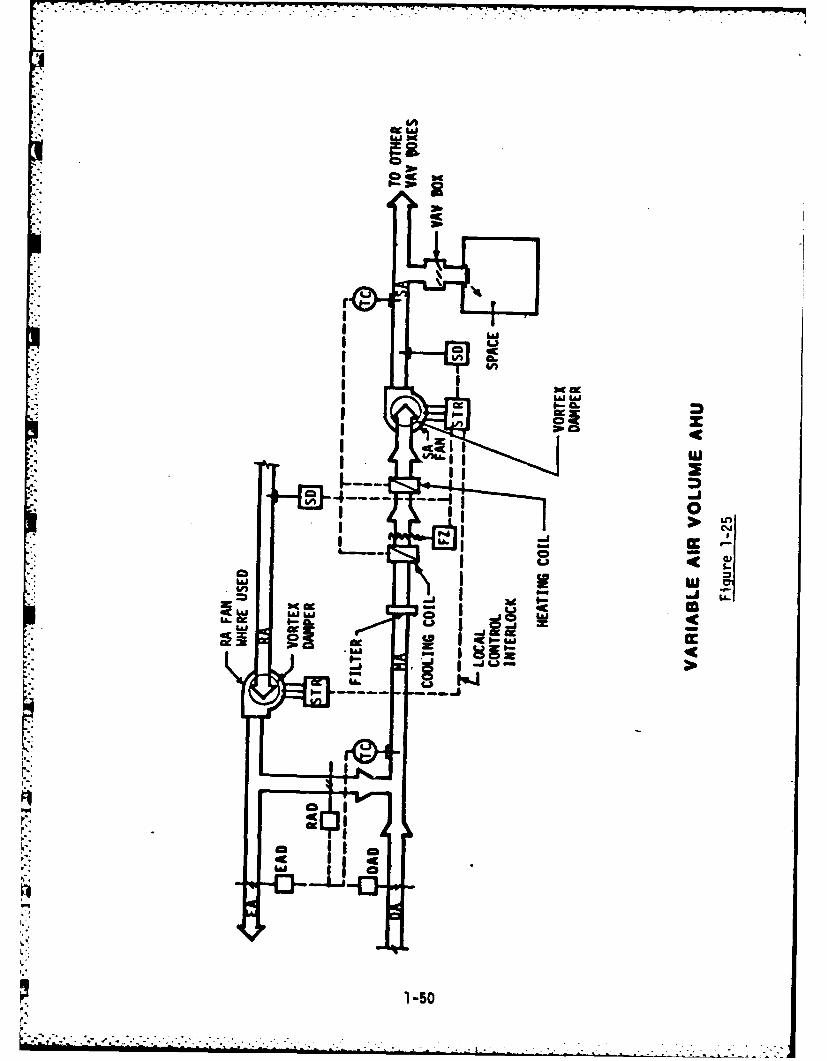
Variable Air Volume Air Handling Unit
All the other central air systems previously discussed have been constant
-' volume, variable temperature type systems. A variable air volume (VAV)
system meets differing zone heating and cooling loads by varying the
quantity of air supplied to a space rather than the temperature of the air.
A VAV system is designed primarily as a cooling system with a constant
supply air temperature between 550 and 60*F. When less cooling is required
- for a particular zone then a control box or damper serving that zone closes
thus reducing the quantity of air supplied to the zone.
- Since most large buildings today are dominated by cooling requirements due
* to the large quantity of interior space versus perimeter spaces, variableair volume systems have become very popular. The VAV system consumes less
energy than the previous three systems discussed by avoiding heating and
cooling the same air. In addition, by varying the air flow rate,
considerable energy savings may be obtained as a result of reduced supply
* fan horsepower requirements. VAV systems also offer added flexibility
since the quantity of air supplied to a space may be easily adjusted by
adjusting the controlling VAV box or damper unit.
AXIAL FAN Figure 1-26 CENTRIFUGAL FAN
1-51

Additional control zones may be added after initial system installation by
simply connecting another zone control box to the main VAV supply duct.
Heating in perimeter zones supplied by VAV systems may be accomplished in a
number of manners. Some perimeter VAV boxes include heating coils so when
heating is required, the air volume is reduced to a fixed amount and then
the heating coil is activated to reheat the supply air. Other approaches
may provide a separate perimeter heating system (either air or radiation
type) rather than reheat the supply-air from the VAV system.
As the individual zone control boxes reduce air flow to the zones, the
total air volume supplied by the VAV system must be reduced. The control
system must monitor and control the pressure in the supply ducts to prevent
over-pressurization or surge conditions as the zone control units reduce
air flow. A static pressure sensor must be located in the supply duct to
control the volume of air delivered by the supply fan.
* . Supply fan volume control depends on the type 'of fan. On a centrifugal
fan, inlet or discharge dampers may be used to control fan volume. On a
vane axial fan, the angle of the fan blades may be controlled to vary fan
volume. In addition to damper control, an increasingly popular method for
DAMPER MOTOR
VORTEXDAMERS
CENTRIFUGAL VAV FAN
Figure 1-27
1-52

' . . .. . ' "". . .'. .
VAV control is the use of variable speed drives. These devices vary the
fan speed to reduce air flow rates and generally result in more horsepower
savings than damper or blade pitch control. Variable fan speed may be
accomplished by mechanical speed control devices which utilize a constant
speed motor through a varying speed drive device. Speed controllers may
vary in motor speed to accomplish the same effect.
Direct Fired Furnace
There are two basic classifications of devices for conversion of fuel to
heat. These are furnaces and boilers. A furnace is generally defined as a
device which directly heats the air in a space or the air being supplied to
the space. A boiler on the other hand, is generally a device which heats
an intermediate medium such as water or steam which is then used to heat
the air supplied to or in the space.
The common residential furnace is the most familiar example of a direct
fired furnace. The thermostat within the space cycles the furnace on and
off to control the temperature. Once the desired temperature is reached,
the thermostat shuts the furnace off and the temperature is allowed to drop
to some lower level at which time the thermostat restarts the furnace. In
addition to the basic thermostatic control, most furnaces incorporate time
delays and safety controls to ensure efficient and safe operation of the
system. In a furnace, the fuel is ignited in some type of combustionchamber and the hot gases which are products of that combustion process
* then pass through a heat exchanger on their way out of the building through
a flue or vent. The heat exchanger generally consists of some type of
multi-path metal enclosure which allows the hot combustion gases to pass
through one side of the heat exchanger while the air to be heated passes
over the other side. Heat is transferred through the metal walls of the
heat exchanger from the hot combustion gas to the cooler air. Heat
exchangers are designed to provide the maximum surface area between the air
to be heated and the combustion gases.
1-53
* * . . .,. * .

~41
I.
1--

' • , ~ - . -- ' , -,. " ; .. .. " " ' "
-
Steam Boilers
A boiler uses the combustion process to heat an intermediate medium which
is then used to heat the space or supply air. Where the intermediate
medium is steam, this device is called a steam boiler. The process used
within the steam boiler is exactly the same as boiling water in a pan on
the kitchen stove. The surfaces of the pan are heated to a temperature
greater than what's called the boiling point of the water within the pan
(2120F at atmospheric pressure). When the water in the pan reaches this
temperature, the temperature remains constant as the water changes form
from the liquid state to the gaseous state. Water in a gaseous state is
* called steam. To convert one pound of liquid water into one pound of
steam, roughly 1,000 btu's of heat energy are required. By the same token,
if steam is cooled below the boiling point, it is converted back into water
and releases roughly 1,000 BTUs per pound of steam which condenses. A
steam heating system takes advantage of these principles by converting
liquid water into steam and transferring that steam from the boiler through
a piping system to the heating coils or radiators. There the steam is
condensed back into a liquid form while heating the air passing through the
. coil or around the radiator surface. Thus, for every pound of water
-' converted to steam at the boiler, 1,000 BTUs are transferred to the steam
"" and for every pound of steam condensed in the room or heating system,
roughly 1,000 BTUs of heat is transferred to the space.
" As water is placed under pressure, its boiling point increases. For
* example, water at atmospheric pressure boils at 2120F. Water at 30 pounds
per square inch pressure above atmospheric boils at 274°F. Water at 100
* pounds per square inch above atmospheric boils at 338*F. All steam boiler
systems operate above atmospheric pressure causing the steam to flow
' through the piping system to the location where it is to be used. Boilers
are generally classified into as high pressure boilers or low pressure
r boilers. High pressure boilers generate steam at a pressure greater than
* 15 psi, while low pressure boilers generate steam at a pressure less than
1-55

LII
-w CL
-a 0Lij 0"
zh
6-
~i
cc
2cw
"SQP0
4.)~C cc__
1-56

. or equal to 15 psi. High pressure boilers are more efficient in that they
* deliver hotter steam at a higher pressure; however, they are more dangerous
and may require on-duty operators for safety purposes.
Steam produced by steam boilers is used in heating devices such as
* radiators, convectors, heating coils, and heat exchangers. Within these
devices, the steam is converted back to the liquid state as heat is
transferred from the steam to the air or water to be heated. These devices
S- are arranged such that as the steam condenses to form water, it drains to a
" lower level where it is collected. A device called a steam trap then
allows the water condensed from the steam (condensate) to be discharged
from the steam piping system. The condensate discharged may be wasted by
allowing it to drain into the sewer system or it may be returned to the
* boiler and pumped into the boiler for reconversion to steam and
recirculation. Wasting condensate was generally practiced before energy
costs were high enough to justify the capital costs of installing a
* condensate return system. Condensate return systems may operate by gravity
* if the boiler is at a low enough elevation to allow condensate to drain
back to7 it. Pumped condensate systems may use either a vacuum pump which
*T places a pressure less than atmospheric on the condensate return system or
- a condensate return pump. The discharge of a number of traps is collected
by gravity into a container called a condensate receiver and then pumped
under pressure into a pressurized condensate return system.
*. In steam boiler systems, the main operating control is based on the steam
supply pressure from the boiler. As steam is condensed in heating coils,
the heating pressure in the boiler supply line drops and a pressure control
* then fires the burners In the boiler to generate more steam. As steam is
*, generated, if it is generated faster than it is used, the pressure within
*the boiler increases and the pressure controller shuts down or reduces the
burner firing. Other boiler controls Include a makeup water controller
which keeps the water level in the boiler at a safe minimum. Some boilers
also include combustion air damper controls. Because boilers can be very
1-57
*i -'- . .. " .* . . . .. , . . . . . ... . ..... ..... ....

dangerous due to their combustion process, and operation at pressurized
conditions, a great deal of effort and expense is spent on safety controls.
High pressure limit controls shut down the fuel flow to the boiler if the
steam pressure goes above a certain level. Low water safeties monitor the
water level within the boiler and if it drops too low, the boiler will shut
down. Flame failure monitoring devices monitor the status of the
combustion process and shut down fuel flow if they detect problems. These
are just a few of the many safety controls required on a steam boiler
system.
Hot Water Boiler
In a hot water boiler, the boiler and piping system are completely filled
with liquid water and arranged such that steam is never provided. The
combustion process within the boiler is used to simply heat up the water
being circulated through the boiler rather than converted to steam. Pumps
are required to circulate the hot water through the boiler and through the
heating system. Hot water operating controls generally consist of a
thermostat which turns on and off the boiler burners in order to maintain a
constant hot water supply temperature from the boiler. Safety controls are
very similar to those for steam boilers except that they are adapted for
water service, instead of for steam service. For example, in place of the
high pressure limit control, a high temperature limit control shuts down
the hot water boiler if the water temperature is too high. Generally, the
hot water circulating pump is electrically interlocked with the boiler so
that when the pump shuts down the boiler will be deactivated.
Convertors
A convertor is a device which is used to transfer heat from one medium to
another. Examples are the use of a convertor to transfer heat from steam
to hot water, from high temperature hot water to low pressure steam, and
from high temperature hot water to low temperature hot water. Basically, a
1-58

3-
BC'C
w
II
~iI 3:j
IP
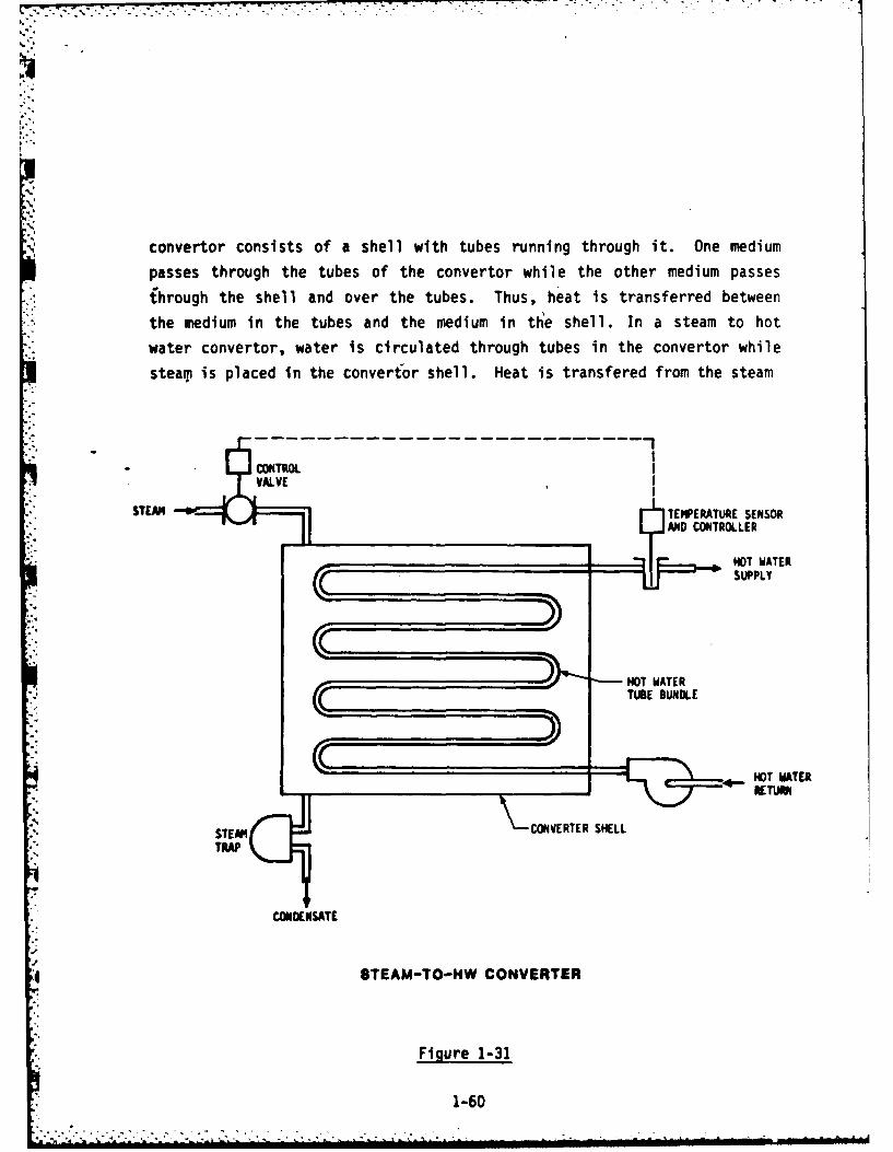
convertor consists of a shell with tubes running through it. One medium
passes through the tubes of the convertor while the other medium passes
,hrough the shell and over the tubes. Thus, heat is transferred between
the medium in the tubes and the medium in tte shell. In a steam to hot
water convertor, water is circulated through tubes in the convertor while
steam is placed in the convertor shell. Heat is transfered from the steam
* CONTROL
STEM TEPERATURE SENSORMD CONTROLLER
NOT WATERSUPPLY
0 1 NOT WATERTUBE BUNDLE
'.'HO WATERMTE
CONVERTER SHELL
TRAP
: CONDENSATE
8TEAM-TO-HW CONVERTER
Figure 1-31
1-60
- -. . h A,

i:0
A1 .j r
-1
"A- J
Ml
1-61

'All
z0CV
1-62

id
I IV-
I =i
I. GA
I101

in the shell to the water in the tubes and the steam condenses. The
condensate then may be returned through a steam trap to the condensatereturn or waste system. A steam to hot water convertor is controlled by a
thermostat in the hot water piping leaving the convertor which controls a
valve on the steam line entering the convertor. As the hot water supply
temperature drops below the controller setpoint, the controller opens the
steam valve to allow more stea)p to transfer into the convertor shell. As
this happens, more heat is transfered to the water passing through the
convertor to increase the supply water temperature. The controls in the
,* hot water pump circulating water through the convertor are usually
electrically interlocked such that if the pump is shut down, the steam
control valve is closed.
Chillers.
A chiller is a refrigeration machine which produces chilled water for use
as the cooling medium in HVAC fan systems and other equipment.
Recall that an air handling system may have either a direct expansion coil
or a chilled water coil for cooling the return air stream. The DX coil is
the evaporator in a refrigeration cycle. Heat is removed from the air
stream passing over the coils as the low pressure refrigerant -vaporizes.
In a chiller, instead of removing heat from air, heat is removed from
chilled water which flows over the refrigerant tubes In the evaporator
chamber. The chilled water is then pumped to the cooling coils throughout
a building.
During the condensing stage of the refrigeration cycle, heat must be
removed from the refrigerant. This may be accomplished by passing either
air or water over the condensing coil. Thus, we have either an air cooled
chiller or a water cooled chiller.
1-64

LA
4AJ
wi -Cri-Q me
tj 1cI
CDI
aLaihJ~ cc
* .. J~1 Z~ L. I
44'
1-65

LL..
0
0
U'U
Cc
1-66

,- Air cooled condensers are located outside where ambient air is forced
. across the condensing coils by either a propeller or centrifugal type fan.
The condenser fan is controlled to start automatically whenever the chiller
i compressor runs. In some situations where low ambient temperatures might
* cause operating problems due to low condensing pressure, it is necessary to
provide additional control. The simplest method uses modulating dampers to
reduce air flow, based on changing refrigerant pressure. Other methods
employ a variable speed fan or a throttling valve on the flow of liquid
refrigerant to vary the cooling capacity of the condenser.
Water cooled condensers are located at the chiller and are supplied with
condenser water from a cooling tower or some other source. In the
condenser water loop, heat is rejected to the water in the condenser and
then from the water to the outside air in the cooling tower. The principle
of heat rejection in the cooling tower is evaporative cooling. As water
falls down through the cooling tower a small amount of it is evaporated.
The latent heat required for the evaporation process is supplied by other
water droplets in the form of sensible heat. Thus, 99% of the water
reaches the tower basin at about 10OF cooler temperature.
The cooling evaporative process is aided by the movement of air through the
tower. Natural draft cooling towers are designed to take advantage of
natural air currents and are therefore located in open spaces. Induced
draft and forced draft cooling towers are provided with a fan to move
atmospheric air through the tower.
In water cooled condensers, condensing pressure can be controlled by
modulating water flow or controlling the condenser water supply
temperature. Water temperature may be controlled by cycling the tower fan
or bypassing some of the condensing water around the cooling tower, using a
control valve and condenser water supply temperature sensor.
1-67

Chiller controls normally include water flow switches in the condenser and
chilled water circuits to prevent the chiller from starting if the con-
denser or chilled water pumps are not running. Starters for the condenser
witer pump, compressor, compressor oil pump are normally interlocked with
the chilled water pump. Safety cutoff relays also are provided to shut-off
the chiller in case of low chilled water temperature, high condenser water
temperature, high condenser pressure, low evaporator pressure or
temperature, high motor temperature, etc. Usually these are internal
.. controls supplied with the chiller by the chiller manufacturer. Also
chillers are usually provided with relief valves or rupture disks, which
are set to discharge the refrigerant in the event of high refrigerant
pressure.
.1-6
-.'
1-6

CHAPTER 2
ENERGY MONITORING AND CONTROL SYSTEMS
I.'
SECTION 1. INTRODUCTION TO EMCS
An Energy Monitoring and Control System (EMCS) is an energy management
system which allows for centralized monitoring and control of dispersed
energy consuming equipment.
Over the past thirty years, energy monitoring and control systems have
undergone an evolutionary process. The evolution has basically been from
strictly monitoring systems to control plus monitoring systems.
Prior to modern EMCS systems, building temperatures, pressure, etc., were
monitored from a central location, generally the building engineer's
office. Panel banks in the office were connected to sensors and
controllers throughout the building. These systems were generally used
only in large individual buildings. Other than to start and stop
4 equipment, the central panel banks offered little control over the
equipment they monitored.
The systems developed in the 60's provided scheduled start-stop and manual
temperature control point adjustments. Temperatures and pressures were
monitored, but instead of gauges and dials, digital displays were
incorporated. One important feature of these systems was the provision for
2-1-: _ ,

reporting alarm conditions. These were the first systems to utilize
computers where monitored data was stored in memory (electronically
recorded and retained for later use). The Central Processing Units (CPU)
had numerous individual signal wire connections which came directly from
each monitored component. Due to technological limitations, making changes
to the systems was severely limited. The manufacturer had to make any
changes. Possible changes were limited to circuitry provided during
manufacturing.
Performance of the hardwired logic units improved significantly as a result
- of combining them with a means to transmit data between various system
components. In these transmission systems, individual sensors and
controllers were wired to a field panel installed near the sensor
locations. From the field panel, the signals were sent on to the CPU.
Technology had been developed such that a number of signals could be
transmitted along the same conductor. Therefore, this system required the
installation of only a two or fcur wire cable from the CPU to panels inmechanical rooms throughout a building instead of the many multi-conductor
cables necessary for previously described systems. Once this system
configuration was developed, multi-building complexes began to utilize the
concept of central monitoring and control. The technical capability to
combine or multiplex signals over a few wires has reduced tremendously the
cost of data transmission media, thereby making the EMCS concept cost
effective for DoD installations. This type system was common on college
campuses and was used in early military base EMCS installations.
A major improvement in system flexibility and performance was the
replacement of the hardwired logic CPU with a small general-purpose
computer. This allowed the manufacturers to easily modify and program the
system. It also provided for greater flexibility in utilizing the
4 monitored information. Data was collected, calculations performed, and
appropriate control commands or alarms sent to the field controllers. The
ability to modify or program the systems was, however, not passed on to the
customer. Consequently, from the customer's standpoint, it was a major
2-2

project to have the manfacturer add a point to the system, change constants
K related to a point, or add specialized instructions for computer operation.In general, only the original manufacturer was capable of performing theseactions, thus resulting in a non-competitive procurement situation.
K The above evolution generally describes the process with which major
conventional controls manufacturers developed the systems they are*marketing today. A different group of manufacturers has appeared on the
*scene within the past five years. These manufacturers are generallysmaller firms with backgrounds in process control applications or generalcomputer systems applications.
Their approach has been to use off-the-shelf computer, data transmission,* and sensor components. The components are combined with computer software
- to form an EMCS. These manufacturers claim to provide greater flexibility
*and adaptability to the customer for less cost. Their main support for
* this argument is that their systems generally allow the customer thecapability to write programs, modify existing programs, and retrieve
monitored data, which is not possible with most of the major conventional*control systems. This has resulted in competition which is now causing a
* re-evaluation of the system design philosophy of the major controlmanufacturers.
* The energy crisis and the advent of computer based systems also brought new
interest and direction to central control applications. The rapid rise of
energy costs, coupled with increased system capability to reduce energy
consumption, has improved the economic feasibility of energy monitoring and
* - control system application. Although the systems have not reduced manpower
* as expected, some manpower savings are possible and will be realized. More
* importantly, the energy conserving control aspects of the systems are of
such value that they can be justified on that basis alone.
* As described above, central control systems have evolved from systems whose
- principal value was the monitoring of points, to systems whose principal
2-3

value is the control of equipment. Because of this process of evolution,
with its inherent inertia, problems have occurred. The engineering design
process has not kept pace with the change in purpose of the EMCS from
monitoring to control. Many recently installed systems include a number of
points whose only purpose is monitoring of equipment, which effect no
direct energy savings.
Various military installations have been involved in all stages of the
evolutionary process described above. Many large individual buildings,
such as hospitals, contain the hardwired central panel systems. The first
base-wide systems which instrumented multiple buildings were procured when
the data transmission system in conjunction with the hard logic CPU became
available. At that time the principal justification for procurement of
such systems was the monitoring of equipment to reduce manpower
requirements. Minimal control was available or emphasized in these early
projects. The installations attained varied operational success, but
virtually all of the systems failed in the manpower reduction objective.
Generally, insufficient funds are available at one time to purchase full
capability for every building on a base. The result of this limitation is
that a reduced system is procured by not connecting some or many of the
buildings on a given base. This approach results in the selection of many
monitoring functions with no associated energy savings in one building,
while another building is not connected to the EMCS at all. An alternative
to this approach is to delete monitoring points from the first building and
connect energy conserving points, or energy control points in the second
building. Whether or not to delete monitoring points is a decision of
management that has to be looked at on an individual basis based on past
experience.
Generally. the design philosophy for military EMCS programs has enlarged to
include the energy conscious approach. Systems now under design are being
configured on the basis of energy savings as well as O&M functions. A
number of complex problems involved in determining the optimum
2-4

configuration of an EMCS for a particular base have been defined as aresult of this enlargement in design philosophy. The complexity of theproblems stems from the inter-relationship of costs to perform alternative
EMCS activities.
Purpose of an EMCS
The prime purpose behind the development and use of EMCS is conservation of
energy. Energy conservation is accomplished primarily through close
monitoring and control of HVAC systems. Traditionally, HVAC systems onmilitary posts were installed building by building during construction orrenovation. Even on posts with centralized steam and/or chiller plants,the buildings were widely dispersed making it impossible to maintain aclose watch over energy consumption. It was nearly impossible to controlenergy consumption so as to conserve it. Heating and cooling equipment was
energized at the start of the appropriate season, usually as a function ofthe calendar and with little regard for unseasonable weather conditions.The equipment was allowed to run continuously until the mandated end of the
season. The usual result was that building occupants were either too hotor too cold and opened windows to regulate the temperature, therebyincreasing energy consumption. Further, HVAC systems ran 24 hours a daybecause there was no feasible way to turn the widely distributed equipmenton and off. There was also no provision for resetting space temperaturesduring unoccupied periods. The EMCS allows 'for both the centralizedmonitoring and control of energy consumption on a widely dispersed HVACsystem. While the prime use for an EMCS is for mnitoring and controllingHVAC equipment, it may also be used for lighting control, sewage liftstation control, maintenance management, and fire and security alarms.
EMCS Attachment to the HYAC System
EMCS systems have been developed to provide centralized monitoring and
2-5

- --- - - - - - -. - - f -- -
control of dispersed energy consuming equipment. An EMCS connects to an
HVAC system through monitor and control points. Monitoring and control
functions are accomplished through use of a computer.
Where the EMCS and an HVAC system connect is called a point. There are two
kinds of points:
1. Control points which allow the EMCS to send information to the
HVAC system in the form of.commands, and
2. Monitor points which sense temperatures, pressures, flow rates,
etc., on the HVAC system and send information to the EMCS. There
are typically five to ten times as many monitor points in an EMCS
as there are control points.
There are two primary types of measurement and control used in HVAC
applications: two position and modulating (proportional). Two position
control devices designate one of two operational modes, such as on/off or
open/closed. Two position measurement sensors detect if the equipment is
on or off, open or closed. Two position type measurement also can be used
to sense whether a measured variable is above or below a set value. For
example, a freezestat can detect whether or not a temperature is above
400F.
. Modulating or proportional control devices set an actuator or motor at any
* position between on or off (open or closed). For example, a modulating
control device may be used to position a valve to regulate the flow of
-: water. As the valve position varies from open to closed, the flow rate of
water varies from full flow to no flow. Proportional measurement produces
a signal whose value is related to the value of a physical parameter. For
example, a temperature sensor produces a output signal which is
proportional to the temperature it is measuring. Such devices generally
have a limited runge over which they operate. For example, a temperature
sensor designed to measure room temperature would be reasonably accurate
2-6

over the range of 500 to 100°F, but would not be accurage for measuring
*- .,boiler stack gas temperatures on the order of IO00°F.
* The types of sensors or output devices used at the monitor and control
points vary depending on their function. The following list presents
examples of monitor point devices and what they monitor.
DEVICE MONITORS
Air flow switch Air flow status
Water flow switch Water flow status
Freezestat Provide warning whenheating or cooling coilsare in danger of freezing
Flame sensor Flame failure
Auxiliary contacts 'On/off status (motors,fans, etc.)
Analog sensors TemperaturePressureHumidityVoltageCurrent
The following are examples of EMCS control points, the devices used and
their function.
DEVICE FUNCTION
Relays Motor ON/OFF
Controllers TemperaturePressure
Typical monitor and control points for a single zone AHU are shown in
Figure 2-1. Monitoring and control point designations are defined in
Figure 2-2.
2-7
- --.,. -.. . . .- - . , : - -, .: ..... . 1 . ..... -. .. . . .-. _..

.4
* - -- -
II
C
0
a.'
C
C0I,'
IC
0a, ~.I..~ 9-0~ 0
.9- 1.-La..4~
C0
- C1-0
4.)I
C0
9-
Li.9-0.
I
I
-. -- 2-7A . - .

itLe1
CY
n0
,4 J
CA0
iLL w
2-8-
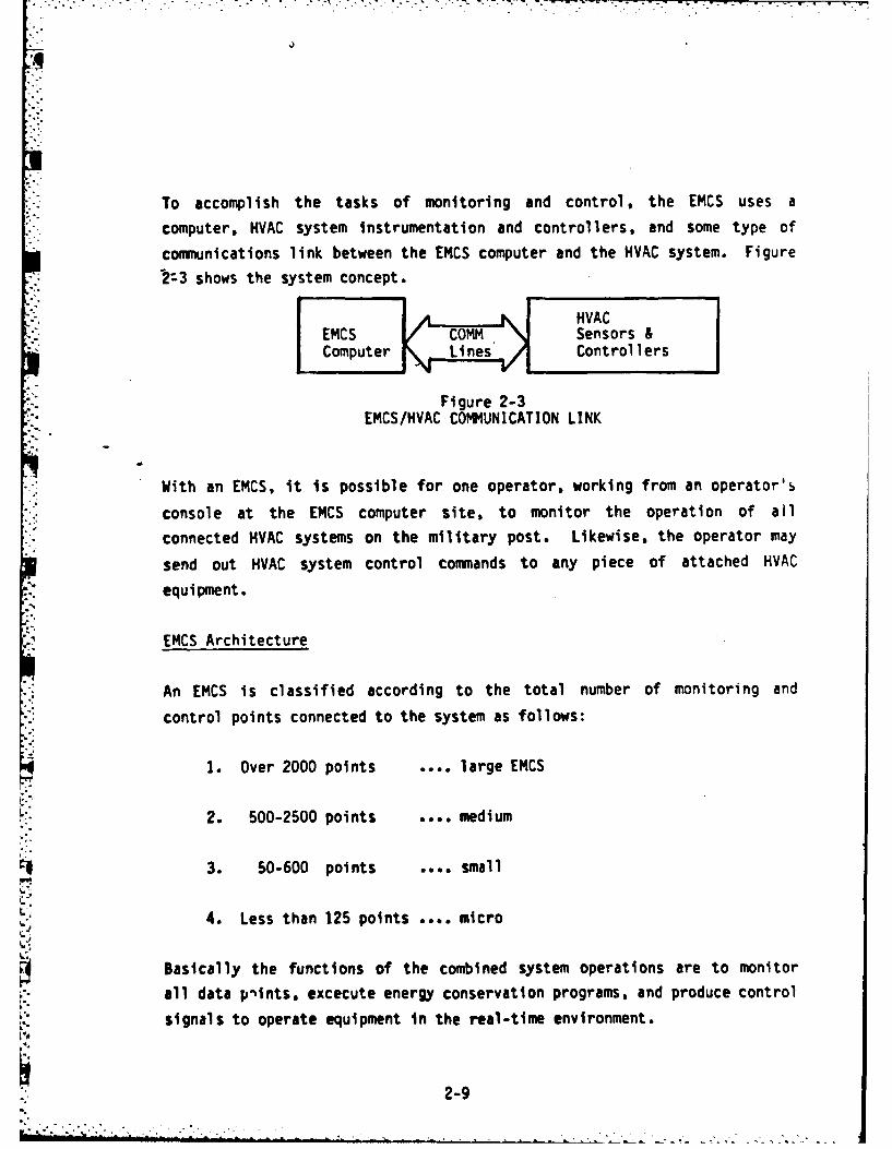
To accomplish the tasks of monitoring and control, the EMCS uses a
computer, HVAC system instrumentation and controllers, and some type of
communications link between the EMCS computer and the HVAC system. Figure
1:3 shows the system concept.
EMCS COMSensors &Computer LnsControllers
Figure 2-3EMCS/HVAC COMIUNICATION LINK
With an EMCS, it is possible for one operator, working from an operator's
console at the EMCS computer site, to monitor the operation of all
connected HVAC systems on the military post. Likewise, the operator may
send out HVAC system control commands to any piece of attached HVAC
equipment.
EMCS Architecture
An EMCS is classified according to the total number of monitoring and
control points connected to the system as follows:
1. Over 2000 points .... large EMCS
!L. 2. 500-2500 points .... medium
3. 50-600 points .... small
4. Less than 125 points .... micro
Basically the functions of the combined system operations are to monitor
all data pltnts, excecute energy conservation programs, and produce control
signals to operate equipment in the real-time environment.
2-9

Large EMCS Architecture
A modern large EMCS consists basically of several small computers,peripherals, and monitor/control equipment. A computer is defined as any
* device whiich can receive and store a set of instructions, and then act uponthem in a predetermined and predictable fashion. Also, the data and
* instructions can be changed. Computer software are the programs whiichinstruct the computer. Figure 2-4 shows the layout-of a large size EMCS.
Copers
*Large EMCS use several copuer systems including the Central Control Unit* (CCU), Central Processing Unit (CPU), and Central Communication Controller
(CCC).
* The Central Control Unit is a small computer that functions as the overall*system coordinator. It implements the energy conservation programs,
performs, complex calculations, and controls peripheral devices. The
Central Processing Unit is the portion of the computer that interprets andexecutes instructions. The software controls operations of the CPU and itsperipheral devices.
While operating under energy conservation programs, environmental
conditions and power consumption rates are predicted. Proper equipment* operating point settings are calculated and control signals are produced to
operate the equipment in actual-time. Data and programs are stored inmemory or mass storage devices such as magnetic tape or disk systems. Forhigh speed transfer of data between the CCU and mass storage device, theCCU has direct memory access (DMA) controllers. The DMA transfers data inblocks. The CCU has designated connections, called Input/Output (110)ports, for specific equipment, such as printers and terminals. It provides
the interface between tho operator and the EMCS. During normal operation,4the CCU coordinates operation of all the EMCS components, except safety
interlocks.
2-10
-s *. * * - . -

UC
DSSY TEM LOAPRIUSC~~hL ~ ISR NT ER
TAPET SYSTEM PRINTE
CF guNeR2-Large ECS Archtectur
.~~~
FAILOV.. .. . . . . . .2 1

-: The Central Communication Controller is a small computer that collects and
dissemhinates data to and from control and monitoring points. In addition
to transferring data, it can change the format of data presentation, check
for errors, and retransmit data between the CCU and other equipment. In
the event of CCU failure, it provides limited backup. The CCC relieves the
CCU of time consuming communications with other equipment; allowing the CCU
to devote its full capabilities to the execution of control, monitoring,
and applications software programs. In the event of CCU failure, the CCC
*provides for limited backup.
Peripherals
Peripheral equipment controlled by the CCU includes the following:
The system terminal is a television screen or cathode ray terminal (CRT)
;. which displays letters and numbers and is used to perform system commands,develop and modify system programs, and run software diagnostic tests.
* The operator's console is an eight color CRT terminal that displays shapes
and colors in additional to numbers and letters. It is the primaryoperator-system interface. It graphically displays equipment schematics,
system status, operating parameters such as temperatures and pressures, and
* operational-data.
The console contains a dedicated keyboard for entry of operator commands.Trends of selected equipment variables can be plotted, enabling the
operator to make strategy decisions regarding equipment operation. Graphic
displays may be brought up automatically when an alarm is activated, or
upon operator command.
Data Storage Devices store data for later use. Disk and tape systems are
utilized. The disks or tapes store information on t;ieir magnetic surfaces
like a tape recorder. Disks are either hard or flexible (diskettes) and
2-12. . * *

:':~~~~~~~~............ -.... ....- ,....._- . . -. .. ... °..., ,
spin like a record. A device called a drive, spins the disk or winds the
tape. It contains a device called a head, which can read information from
the magnetic surface as well as write information. The computer can move
the head to any location on the surface of a disk. This is called random
access. The storage systems used in an EMCS include:
The cartridge disk is a high density mass storage system with random access
and removable disk capability., It is used to store the EMCS system,
command, and applications programs.
Z : The Winchester disk can also store the EMCS operational programs and
instructions. It is a high density mass storage system with random access.
The disks are extremely susceptible to dust, dirt, and cigarette smoke.
Therefore, the system is sealed and the disks cannot be removed. Because
of manufacturing technology, Winchester disks are more reliable than
cartridge disks.
A flexible or floppy disk is a medium density storage system with random
access and removable disk capability. They are utilized for giving
start-up instructions to the computer and historical data storage. The
diskettes are circular vinyl disks. enclosed in rigid plastic envelopes.
The envelope protects the diskette during handling and use. Openings in
the envelope allow the head access to grip the diskette surface. The
diskette spins freely inside the envelope and is driven by the head. The
diskette should never bi removed from its envelope.
A magnetic tape system is a nine-track high density mass storage system,
with removable tape capability. Data is stored and accessed sequentially,
making data retrieval slower than from a random access disk systfo. They
are used when large amounts of data is stored but will be accessed only
periodically.
Two key-board printers are provided with a large EMCS. They are used to
obtain permanent copies of data or system operations. The alarm printer is
2-13

771. 7,.1
dedicated to reporting alarms. The logging printer logs data and prints
reports. Each must be capable of serving as a backup for the other.
The EMCS system clock must be synchronized with an actual-time clock a;
regular intervals. This Is done with the System real-time clock (RTC)
which is provided with a battery backup.
A failover controller is provided for automatic and manual switching of the
'- CCU, CCC and printers to the backup mode of operation should the CCU, _C
* or printers fail.
A bulk loader, is a mass storage-device used to load EMCS software into the
- system.
* The central control unit, central communication controller, operator's
console, system terminal, data storage devices, printers, and other
peripherials are located in the master control room (MCR).
The Communications link termination (CLT) is the communications inte-,
between field equipment and Master Control Room (MCR) equipment. It
concentrates data, as required, for interface to the CCC/CCU.
Field Equipment
The following components make up the field equipment, which is located in
the vicinity of the data environment, (sensors and control devices
connected to a single FID/MUX/IMUX from the equipment and systems sampled
or controlled).
Field Input Device (FID)
Multiplexer (MUX) Panels, and
Intelligent Multiplexer (IMUX) Panels.
2-14
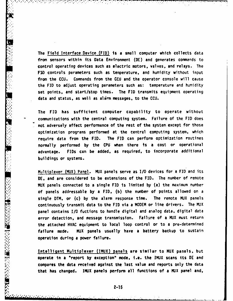
- -.-.,."
The Field Interface Device (FID) is a small computer which collects data
from sensors within its Data Environment (DE) and generates commands to
control operating devices such as electric motors, valves, and relays. The
FIO controls parameters such as temperature, and humidity without input
from the CCU. Commands from the CCU and the operator console will cause
the FID to adjust operating parameters such as: temperature and humidity
set points, and start/stop times. The FID transmits equipment operating
data and status, as well as alirm messages, to the CCU.
The FID has sufficient computer capability to operate without
communications with the central computing system. Failure of the FID does
not adversely affect performance of the rest of the system except for those
optimization programs performed at the central computing system, which
require data from the FID. The FID can perform optimization routines
normally performed by the CPU when there Is a cost or operational
advantage. FIDs can be added, as required, to incorporate additional
buildings or systems.
Multiplexer (MUX) Panel. MUX panels serve as I/O devices for a FID and its
DE, and are considered to be extensions of the FID. The number of remote
MUX panels connected to a single FID is limited by (a) the maximum number
of panels addressable by a FID, (b) the number of points allowed on a
single DTM, or (c) by the alarm response time. The remote MUX panels
continuously transmit data to the FID via a MODEM or line drivers. The MUX
panel contains I/O fuctions to handle digital and analog data, digital data
error detection, and message transmission. Failure of a MUX must return
the attached HVAC equipment to local loop control or to a pre-determined
failure mode. MUX panels usually have a battery backup to sustain
operation during a power failure.
Intelligent Multiplexer (IMUX) panels are similar to MUX panels, but
operate in a "report by exception" mode, i.e. the IMUX scans its DE and
compares the data received against the last value and reports only the data
that has changed. IMUX panels perform all functions of a MUX panel and,
.. 2-15
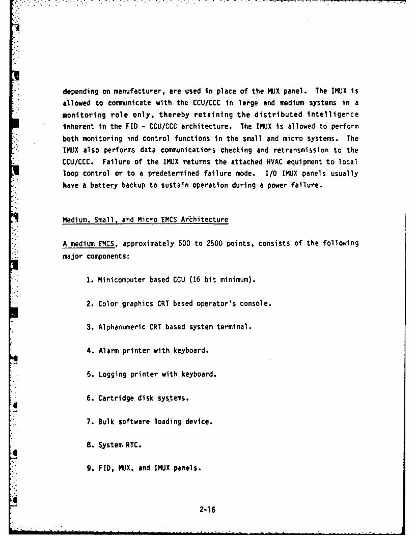
depending on manufacturer, are used in place of the MUX panel. The IMUX is
*::. allowed to communicate with the CCU/CCC in large and medium systems in a
monitoring role only, thereby retaining the distributed intelligence
inherent in the FID - CCU/CCC architecture. The IMUX is allowed to perform
both monitoring ind control functions in the small and micro systems. The
IMUX also performs data communications checking and retransmission to the
CCU/CCC. Failure of the IMUX returns the attached HVAC equipment to local
loop control or to a predetermined failure mode. I/0 IMUX panels usually
have a battery backup to sustain operation during a power failure.
Medium, Small, and Micro EMCS Architecture
A medium EMCS, approximately 500 to 2500 points, consists of the following
major components:
1. Minicomputer based CCU (16 bit minimum).
2. Color graphics CRT based operator's console.
3. Alphanumeric CRT based system terminal.
14. Alarm printer with keyboard.
5. Logging printer with keyboard.
6. Cartridge disk systems.
7. Bulk software loading device.
8. System RTC.
9. FID, MUX, and IMUX panels.
2-16

10. Magnetic tape system (optional).
11. CLT.
The three components of a large EMCS, not incorporated into the mediumsystem are the central communication controller, failover controller, and
bulk loader. The typical medium EMCS architecture Is shown In Figure 2-5.
A small EMCS, approximately 50 to.600 points, consists of the followingmajor components.
1. Minicomputer or microcomputer based CCU.
2. Alphanumeric CRT based operator's console.
3. Alarm and logging printer.
4. Bulk software loading device.
5. System RTC.
6. FID, MUX, and IMUX panels.
7. CLT.
A typical configuration is shown In Figure 2-6.
A micro EMCS, less than 125 points, consists of the following major
components.
1. Microcomputer based CCU.
2. System RTC.
2-17

MUXKl'IG MU
LOA911 MIN R 0RN91
F GI I D LSIU OE~OIACGWeT
FID gure 2-5MeimEC Acietr
U mux mu2-18

CPU
I FLEXIDLE PRNE
FID IMUXIMUX
%---T CA.63E OWu 90 ShUETfO
'--- - TO . .. W COTROLS-AM-------N S1Ok ----

3. IMUX panels.
4. Progranining and service panel (removable).
5. CLT.
A typical configuration is shown in Figure 2-7.
2-20

I PROGRAMING OPTIONAL1AND SERVICE PANEL I--iALARM ANDI(REMO VABLE) I NDICATION
L.---------------
MAIN
IMUX IMUX IMUX
"*-TO LOCAL SYSTEM CON'TROLS AND INSTRUMENTION(DATA ENVIRONMENT)
Figure 2-7Micro EMCS Architecture
2- 20A

,I..
SECTION 2. OPERATOR INTERACTION WITH THE EMCS
The operator's terminal is the communication link between the operator and
the EMCS equipment. Even though an EMCS is computer controlled, there is
still a need for human intervention. The console accepts operator commands
and displays data and graphical representations of systems controlled or
monitored by the EMCS. Using the console the operator may initiate
software programs, control various equipment, and adjust setpoints. The
EMCS monitors and controls energy consuming equipment such as motors, fans,
water chillers, etc. Should equipment malfunction, an alarm is relayed to
the operator.
There are four basic types of operator interfaces which may be encountered
on EMCS's. The four different types include command language, command line
mnemonic, menu penetration and interactive color graphics.
Command Language
The command language interface technique uses a black and white CRT
terminal. The basis of the command language interface is a command
library, consisting of abbreviated (2 to 5 characters) symbolic "words",
or commands. A basic command word will usually have associated with it a
number of modifiers or arguments, which follow the command word and are
separated by some type of punctuation symbol, such as a comma, semicolon,
or slash mark. Figure 2-8 shows some examples of typical commands.
KIL, LOOP NAME/ALLTIM,HOUR, MINUTESLOC, Ll,<L2>, (L3>LOG, (Ll>,(L2>,<L3>,(OUTPUT DEVICE>
* RM, L1, L2, L3, <DEL>CHL, LI, L2, L3. <DEL>AHU, L1, L2, L3, <DEL>FSI, <DEVICE)
Figure 2-8Sample Command Library
2-21

The operator controls the HVAC system by typing on the CRT keyboard the
appropriate command for the desired function. Command libraries can
contain hundreds of different commands, and these must be learned by the
olerator, or looked up in some reference book, for the operator to be able
to use the EMCS. The EMCS responds to the operator by displaying similar
symbolic words on the CRT screen. The command language technique features
a very precise, rapid interaction with the EMCS computer. However, this
precision of interaction has the undesirable side effect of making the
technique inflexible and unforgiving. If the operator mistypes a command,
omits a required modifier, or misplaces even a comma, the EMCS will not
recognize the command and will respond only with an error message like
"syntax error". The command language interface technique was the first one
to be used with EMCS's and will be found in a large majority of operating
systems.
i .Command Line Mnemonic
The command line mnemonic (pronounced nee-mon'-ic) interface technique
represents a step taken towards improving the "friendliness" of the
operator interface with the EMCS computer, i.e., making the system easier
to use. The command line mnemonic (CLM) interface also uses a black and
white CRT terminal, but unlike the command language interface, the CLM
prompts the operator for necessary inputs with plain English phrases or
words. The operator initiates the input sequence with an English-like
command word. The EMCS computer thereafter prompts the operator for
command modifiers or arguments until all input requirements are met. The
operator then presses the "ENTER" key, which terminates the current input
routine and sends the input commands on to the EMCS computer. In the
computer, a software program called a CLM interpreter (CLMI) reads and
.*Q translates the input command sequence. The CLM interface is much slower to
operate than is the command language interface. This is because with the
CLM, the computer generates multiple cues and responses for each input
22-22
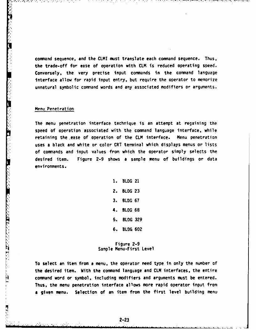
'17
*-: command sequence, and the CLMJ must translate each command sequence. Thus,
the trade-off for ease of operation with CLM is reduced operating speed.
Conversely, the very precise input commands in the command language
i .interface allow for rapid input entry, but require the operator to memorize
unnatural symbolic command words and any associated modifiers or arguments.
Menu Penetration
The menu penetration interface technique is an attempt at regaining the
speed of operation associated with the command language interface, while
* retaining the ease of operation of the CLM interface. Menu penetration
* uses a black and white or color CRT terminal which displays menus or lists
of commands and input values from which the operator simply selects the
desired item. Figure 2-9 shows a sample menu of buildings or data
* environments.
1. BLDG 21
2. BLDG 23
3. BLDG 67
4. BLDG 68
5. BLDG 329
6. BLDG 602
Figure 2-9Sample Menu-First Level
To select an item from a menu, the operator need type in only the number of
*. the desired item. With the command language and CLM interfaces, the entire
command word or symbol, Including modifiers and arguments must be entered.
Thus, the menu penetration interface allows more rapid operator input from
a given menu. Selection of an item from the first level building menu
2-23

shown in Figure 2-9, results In the system displaying a second level menu
of equipment types, shown in Figure 2-10.
1. General
2. Air Handling Equipment
3. Heating Equipment
-.4. Refrigeration Equipment
Figure 2-10Equipment Menu-Second Level
Operator selection of an item from the equipment menu causes the EMCS
computer to display a third level air handling equipment menu, Figure 2-11.
I. AHU 0 1
2. AHU 1 2
3. AHU # 3
4. AHU # 4
5. RELIEF FANS
Figure 2-11Air Handling Equipment Menu-Third Level
This process of penetrating from menu level to menu level continues until
all of the required inputs to accomplish a desired function have been
completed. The process of penetrating through the levels of menus takes
additional time compared to the very precise command language inputs,
however, the simple single key stroke entry saves time and requires almost
no typing skill on the part of the operator.
224
" %-, o. % . . . . , . • .- .. .. . _

'-'~~~~~................... " " '- -"""'' " L ?/..-... ' ' . . ... ,..: .-
Interactive-Color Graphics
The interactive color graphics (ICG) interface technique is the latest
development in operator interface technology, and promises to provide the
fastest and easiest to operate interface produced to date. The ICG
interface uses a color CRT terminal equipped with a touch interactive
feature on the CRT screen. Figure 2-12 shows the presentation provided on
the ICG interface CRT. The basis for operator interaction with the
terminal is a schematic-like diagram of the data environment HVAC system,
and a set of touch-activated "push-buttons". By simply touching the
appropriate "push buttons" and EMCS point interactive touch targets on the
CRT screen, the operator can accompllsh all of the typical control
*- functions listed in Figure 2-13. The only typing required is the inputting
of numerical values when called for by cues to the operator appearing along
the lower edge of the ICG screen. None of the three previously described
interface techniques (command language, CLM, menu penetration) has
incorporated any type of diagram of the HVAC system being controlled. In
* early systems, the only way for an operator to identify devices and
equipment within the controlled HVAC system was by reference to a
computer-printed table. Tabular data does not provide a very graphic
description of a system and is certainly not the type of presentation
" familiar to typical EMCS operators. Most EMCS operators come from the
* ranks of HVAC mechanics, and thus are accustomed to working with
schematic-like diagrams of systems. To overcome the lack of graphicinformation associated with early EMCS operator interfaces, manufacturers
provided 35 mm slides of system diagrams in projector devices located in
the EMCS control room. Thus, to identify a given air handler in a
building, the operator would have to flip through the slides to find the
appropriate building diagram. As EMCS operator interface technology moved
to the menu penetration scw -me. ve, ,s began to provide color graphic
CRT's for the EMCS control ro,.. upon which could be displayed full color
HVAC system diagrams as called by the operator from a menu. The next
logical step in interface development was to combine the necessary
'----25

LA-
2- C-
II--LILI
Ix
La II L~ ~.e1l6
4-
* LO
IL 2D--LAJ 0-4r-
CLiUWa0 EiI ij
2-26a C

idiagrammatic HVAC system display with the required operator command input
capability. Thus, the ICG interface uses elements from all of the previous
interface techniques to make the EMCS fast and easy to operate.m0 Request a display of any digital or analog point, or
any group of related points in the system.
o Startup and shutdown of selected systems or devices.
o Initiate reports.
o Request graphic displays.
o Modify time and event scheduling.
o Modify analog limits.
o Adjust setpoints of selected controllers.
o Select manual or automatic control modes.
o Enable and disable individual points; disabling shalltake precedence over all other actions.
o Enable and disable individual FIDS.
o Enable and disable individual MUX or IMUX panels.
o Point definition.
* Figure 2-13Operator Tasks
Operation of the ICG Terminal
The operator's terminal consists of a keyboard and CRT display screen. The
display screen is equipped with an interactive touch panel. Approximately
one Inch in front of the screen is an array of infrared beams which are
2-27
Continuously sent from the top to bottom of the screen area. The beam can
be interrupted by an object such as a pencil or finger. This allows the
*operator to interact directly with information presented on the screen.Ttris minimizes the need for typing.
The screen is divided into five major areas:
1. Date/time/operator (continuously displayed)
2. Graphics display area
3. Special function keys
4. Message/text area, and
5. Alarm indicator.
The screen layout is shown in Figure 2-14.
The alarm area will be blank under normal conditions. Under an alarm
condition the area will flash in red. The date, time, and operator's name
are entered from the keyboard.
SPECIAL FUNCTION KEYS
Ten Special Function keys allow the operator to instruct the computer toperform complicated commands by simply touching the screen.
The START/ENABLE key is used to manually start mechanical equipment and toenable monitoring and control components such as a FIB, 9UX, or data point.
The STOP/DISABLE key Is used to manually stop mer',anical equipment and todisable monitoring and control components.
2-28

04 q
LcLr
0. - >- z LI4c 4c0CEwJ0. V) I. Qw0*% ==
4c C.J- I- I
LLii(I LL- 4 w_
I-- Ur V-1 C* pe. U;U 09 4~ ii ( ~C1
z
toor
2-29

The DISPLAY DIAGRAM key is used to display HVAC diagrams of specific data
* environments (DEs) in the graphics display area. When the DISPLAY DIAGRAM
key is touched a list of the DEs possible for selection is presented in the
graphics display area. When the square beside the desired area is touched,
the square will change color to indicate that it has been selected. When
the CONFIRM ACTION key is touched it becomes backlighted, the DISPLAY
DIAGRAM key backlight extinguishes, and the selected diagram is presented
in the graphics area.
The AUTO/MANUAL key is used to select or indicate the operating mode of a
- - -particular data environment. This key has three different representations
on the screen:
1. When no DE is being displayed, the key will read "AUTO" or"MANUAL" in black letters.
2. When a DE running in an automatic mode is displayed, the key willhave "AUTO" printed on it in blue letters.
3. When a DE is operating in a manual mode, the key will read"MANUAL" in green letters. To change the mode of a device touchthe device to be 'changed then to the CONFIRM ACTION key toexecute.
The PRINT REPORT key allows the operator to initiate printing of special
reports. Touching the key will result in a list of available reports to be
displayed on the screen. The message "Touch Square Beside Desired Report"
will appear in the text area. Touching the CONFIRM ACTION key will result
in the report being printed.
The MODIFY SCHED key is used to modify the automatic schedule of operation
for a particular data environment. When a DE is displayed, touching the
MODIFY SCHED key results in a list of schedule selections being displayed
* on the screen. The procedure to modify a schedule is the same as that for
changing point settings or limits: touch the square beside the desired
2- 2.30

" selection; type in the changes; after all changes have been made, touch the
-CONFIRM-ACTION key.
The CHANGE OPER key is a multipurpose function key for changing operator or
operation. It allows the operator to shut down the system, request the
" HELP program, or change operators. When the key is touched these messages
are displayed, "Ready to Change Operator/Operation" and "Enter Command or
New Operator Name From Keyboard." The system will then accept one of three
commands: Operator Name, HELP, or STOP. Type in the desired command
- followed by the Return Key. When an operator's name is typed in, the
system assumes that an operator change is taking place and that future
commands should be recorded under a new name. The HELP command is used to
*enter the on-line HELP program. The STOP command may be used to shut down
*- the EMCS.
*The CONFIRM ACTION key is used to assure the system that the desired
*command sequence has been entered and ready to be executed.
The CANCEL ACTION key performs the opposite function of the CONFIRM ACTION
key. It can be used any time prior to touching the CONFIRM ACTION key, to
signal the system to abort the current command and return to the previous
state.
To adjust setpoints or limits of a point of an HVAC system displayed in a
diagram, the SET POINTS/LIMITS key must be touched. The key will become
.- backlighted, and "Touch Appropriate Device Symbol" will appear in the text
area. When the device symbol has been touched the message "Touch CONFIRM
ACTION" will be presented in the text area. Once the confirm action key is
touched, a list of set point, low limit, and high limit with touch
sensitive squares will be presented, as shown in Figure 2-14. The low and
4 high limits being the minimum and maximum desired values for a points.
One or all points or limits can be changed one at a time. Limit changes
are made by touching the desired selection and typing in the desired value
after the message *Please Type In the New Value" appears in the text area.
2-31

The confirm action key must be touched after the final limit has been
changed.
Floppy Disk Drive Operation
in many EMCS's, the computer software programs are loaded into the machine
from a floppy diskette. The diskette comes in two envelopes. The outer
one must be removed to load the diskette, the inner envelope is permanently
fixed and must never be removed. The first step in loading a diskette is
to open the loading slot door on the disk drive un4t. This door will
usually have some simple type of latching mechanism which is released by apinching motion with the fingers. Remove the diskette from its outer
envelope, and hold it in the right hand with the thumb on top of the
diskette label. Gently push the diskette all the way into the loadingslot, then close the disk drive door by pushing on the handle. To remove a
diskette, simply release the latch on the door and the diskette will pop
out of the slot. The disk drive power switch must usually be actuatedmanually. When handling a diskette, do not touch the plastic diskette
surface with the fingers. Diskettes must be stored away from high heat
sources and magnetic devices.
6
Additional Operator Functions
In addition to monitoring and controlling HVAC equipment through use of the
*i operator's console, an EMCS operator has several other functions or duties
to perform. From time to time the operator will be required to perform
minor equipment maintenance, such as replacing ribbons and paper on the
printer, trouble shooting equipment in the main control room (MCR),
possibly replacing circuit boards to restore equipment to normal operating
condition. An operator will also occasionally have to "boot-up" or restart
- the EMCS computer programs. Equipment maintenance and program restartprocedures are site peculiar, and will be governed by local operating
2-32

7 -79.
Instructions and taught as part of the vendor's training, the EMCS
operator is also responsible for safeguarding of the EMCS computer
i programs. In most EMCS Installations, the computer programs are the
proprietary material of the system contractor and may not be given out to
any unauthorized individuals. Locking cabinets are usually provided in the
NCR for storing this proprietary material.
Another important factor is that the EMCS operator is only one part of a
team of individuals who must work in a coordinated manner if the EMCS is to
fulfill its goal of energy conservation. The EMCS operator in the NCR is
the focal point, but Interaction with both base management and HVAC
maintenance personnel is vital. Base management personnel must be informed
as to the capabilities, limitations and objectives of the installed EMCS,
so that they will be supportive in establishing necessary operating
policies which are not always popular with base tenants. Likewise, HVAC
maintenance personnel must understand what the EMCS can do for them, how it
- can help them in locating the cause of trouble calls and in doing
preventive maintenance.
2-33

-o .
SECTION 3. EMCS APPLICATIONS SOFTWARE
The ENCS applications software consists of a group of programs, residing in
the memory of the central processing unit (CPU), that monitor and control
the operations of various HVAC, mechanical, and electrical systems. Each
program attacks a different aspect of a base's energy consumption. While
the primary function of this software is to reduce energy consumption,
other programs may be included in a particular installation to provide
functions such as maintenance management and security alarms.
The identification used for a particular energy conservation program varies
among individual manufacturers. Their methods and approach to a particular
task may also vary. The strategy used depends on the particular software
or hardware a manufacturer uses to accomplish each task, rather than the
task Itself. Generally, the applications software is provided by the
manufacturer In standardized packages, but custom energy saving programs
may be included to accomplish a specific task peculiar to the site.
Discussed below are nineteen applications programs which are required by
*the Tr-Services specifications for large EMCS installations. Each will be
described in terms of what it is designed to do, how it conserves energy,
* -and how it interacts with the operation of typical equipment. Figure 2-15
lists various mechanical and electrical systems and the applications
- software applicable to each. Whether a program is employed in the control
of an individual system depends on many factors which affect the EMCS
design, such as economic feasibility, special environmental requirements,
and safety considerations. For instance, although the Scheduled Start/Stop
program can be applied to a single zone air handler, it would not be
implemented on an air handler serving a microbiology laboratory which
requires a room temperature of 65°F to 70°F at all times.
2-34

w ..
d 4 "
NEAC
ISingle Zone 0 0 0 0
AHU.,'...-". ~2 Terminal Re- • • • • • • • •
heat AHW _
i'.'. ~3 Varlabs Air • • • • • • •
U G'- ,-0 4Vol a . ei
S.hultl-ZoneANU
5 Sinle Zne o
DX-AIC -
6 hult-Zon* 0 00@ 0DX-A/Ci:-: D) -AIC
7 TwoPiperan O * * *• Coil Unit
8 Four Pipe Fan 0 0 0 0 0-Coil Unit
9 Heating Vent-ilating Unit 0
10 Steam UnitHeat -
11 Electric • * * * *Unit Heater
.2 Hot WaterUnit Heater _
13 Steam i onRadiation
14 Electric * * * • *Radiation
15 Hot WaterRadiation
16 Steam 0RollerI-
17 Hot Vater 0Soiler
18 Direct Fired * * * * *Furnace
19 Direct Fired 0 0 0 * •
20 Steam MWConverter
21 HTHW SteamConverter _ -
22 IHfTHHWCoverter
23 Water Cooled 0 * * *DX Co, ressor ...
24 Air CooledDX Compressor
25 Air Cooled * * *. 00Chiller
-26 Wter Cooled * * *. 0• 00Chiller
27 Lightin, - .Cotrol
28 DMaetic NW
29 octc IWGasrl
*Select 9conomlaer or rnthalpy*4Cewrfugal Chiller. oDly
Figure 2-15
2-35

Scheduled Start/Stop
The Scheduled Start/Stop program consists of starting and stopping equip-
ment based on the time of day and type of day. Type of day refers to
weekdays, Saturdays, Sundays, holidays, or any other day which has a
different schedule of operation. This is the simplest of all EMCS func-
tions to implement. In this application, the EMCS serves as a time clock.
However, whereas a time clock has limited capability to provide varied
schedules for large numbers of buildings, the EMCS scheduled start/stop
program is very adapable. Most EMCS provide an eight day schedule, the
five normal workign days (Monday-Friday), two normal weekend days (Saturday
and Sunday), and a holiday. This scheme provides flexibility in scheduling
on a day-to-day basis and allows the system to easily accommodate schedule
changes due to holidays by simply designating a particular week or weekend
day as a holiday, rather than reprogramming all data environment schedules.
This program provides potential for energy conservation by turning off
equipment or systems during unoccupied hours. Automatic scheduling of HVAC
equipment saves energy in three primary areas:
- Electric energy for fans and/or pumps
- Cooling energy for ventilation air and heat gain into the space
- - Heating energy for ventilation air and heat loss from the build-
ing
To get a feel for the amount of energy which can be saved by Scheduled
Start/Stop, let's look at a central air handling system with a fan that
draws 2 kw of electricity. The unit serves office space which is normally
occupied from 8:00 to 5:00, Monday through Friday. The EMCS can beprogrammed with a weekly schedule to operate during occupied periods plus
two hours each morning before people arrive, and skip all holidays. If
prior to EMCS installation the system as allowed to run continuously the
- fan alone would consume
2 KW X 8760 hr/yr - 17,520 kwh per year.
i2-36

S . . .- - -. . . .
Under control of the EMCS the fan would consume
2 KW x (55 hr/wk x 52 wk/yr - 11 hr/day x 9 holldays/yr) - 5,522 kwh
per year
Therefore, the fan would use less than one-third of the energy previously
consumed.
In addition to fan energy savings, less fuel would be burned at the boiler
serving the air handler during, the winter, and less electricity would beconsumed by the refrigeration equipment providing cooling medium to the
unit in the summer. The schematic in Figure 2-16 illustrates the relative
annual savings possible from the example in a location such as Washington,
D.C.
4 • °mAING S
:NET
SCHEDULED START/STOP SAVINGS OF ENERGY CONSUMEDFROM CONTINUOUS OPERATION OF HVAC EQUIPMENT
Figure 2-16
4i 2-37

The points generally included for each system under the Scheduled Stop/Start program are:
Honitoring-(1) Equipment status, provided by a differential pressure
, switch, a flow switch, or auxiliary contacts.
Control-
(1) Start/Stop control signal to interposing relays.
. The equipment status, although not mandatory, verifies that the command has
* been carried out and provides the EMCS operator with an alarm when theequipment fails or is locally started or stopped. HVAC systems connected
- to the EMCS generally include a space temperature sensor which prompts the
EMCS to over-ride the shutoff if the temperature drops below a certainlevel. The EMCS operator needs to continually update the equipment sched-
ules for each system based on current occupancy schedules and seasonal
mode of operation. It is recommended that some procedure be established
for communicating occupancy schedule changes to the EMCS personnel.
Optimum Start/Stop
An ideal FVAC system, which could instantly create comfortable environ-
mental conditions, would save the maximum amount of energy when controlled
under the Schedule Start/Stop program. The operation of the ideal HVAC
system is demonstrated in Figure 2-17. In actuality the HVAC requires a-. finite amount of time to bring the conditioned space to the desired tem-
perature as in Figure 2-18; therefore, the HVAC system needs to be started
before occupancy.
2-38

;"'" - OCUP] ED.
'"". PERIOD
-IK-CCUPI ED THERMOSTATSETTING
_'SPACE TEPERATURE
SYSTEM OFF SYSTEM ON SYSTEM OFF
IDEAL NVAC SYSTEM OPERATION
Figure 2-17
2
4 2-39
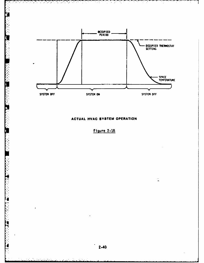
OCCUPIEDH-PERIODI O7CC-UPI ED 1HWE -M 'ST A
SETTING
SPACEV1 TEMPERATURE
SYSTM OFF SYSTEM O1R SYSTEM OFF
ACTUAL NVAC SYSTEM OPERATION
Figure 2-1B
2-40

With a conventional timeclock or a straight Scheduled Start/Stop program
the system is set to start and stop the same time every day. Due to the
variation in weather conditions, the actual amount of time required for
warm-up or cool-down varies from day to day. It also may not be necessary
to operate the HVAC system up until the scheduled departure of the
occupants, because buildings are capable of retaining comfortable space
conditions for short periods without heating or air conditioning. This is
due to the heat storage capability of building materials which creates a
"flywheel effect".
The Optimum Start/Stop program'can save additional energy by automatically
starting and stopping the system on a sliding schedule. The program will
adjust start/stop times by taking into account the thermal characteristics
-"'of the building, the capacity of the HVAC system to either increase or
reduce space temperatures, outside air temperature, and current space
temperatures.
*Figure 2-19 tracks the space temperature fluctuations of a typical system
for three different weather conditions during the heating season. Points
- A, B, and C represent the latest possible start times for the different
conditions, such that the space will reach a satisfactory temperature by
the scheduled arrival of occupants. Under conventional timeclock control
or the Start/Stop program the system would have to be scheduled on at a
fixed time A each morning. Under control of the Optimum Start/Stop
program, the EMCS computer can calculate the optimum start times and save
energy by delaying system startup until those times, such as B and C.
2-41

i . II III I
OCCIED UNOCCUPIED I PRE-HEAT I OCCUPIEDPERIOD PERIOD PERIOD I PERIOD
I NII
ICIOCIO,
I "I I ,
A B C
TIME
OPTIMUM START TIMES
Figure 2-19
The EMCS computer is capable of improving predicted start/stop times based
on past history of start/stop times and resulting space temperature
profiles. The successful implementation of the Optimum Start/Stop program
* can increase the savings achievable by Scheduled Start/Stop by 10%.
The points generally included for each system under the Optimum Start/Stop
*' program are
Monitoring-
(1) Equipment status, provided by a differential pressure
switch, a flow switch, or auxiliary contacts.
"-(2) Space dry bulb temperature sensors, at least one.
* (3) Space relative humidity sensors, needed only if humidity
control is required.
(4) Outside air dry bulb temperature sensor, one for entire EMCS
is sufficient.
2-42

(5) Outside air relative humidity sensor, one for entire EMCS is
needed if humidity control is required.
(6) Chilled water supply temperature, if applicable.
(7) Hot water or steam temperature, if applicable.
Control -
(1) Start/stop control signal to interposing relays.
Generally, the EMCS operator will not have to make any parameter changes to
the program. An occasional check on the start-up and shut-down spacetemperature profiles will be adequate to ensure that the maximum energy
savings are being achieved. However, in some systems the operator has an.- additional input parameter value called a multiplier. By varying the value
- of the multiplier, the operator can manually fine tune the optimum
start/stop program to maximize energy conservation. In some installations
it may be necessary for the operator to adjust the program parameters when
-- switching from heating to cooling mode and vice versa.
DUTY CYCLING
The duty cycling program saves energy by turning energy-consuming loads on
and off periodically when their continuous operation is not necessary.
This program is normally only applicable to heating, ventilating, and air
conditioning systems. Some typical applications for duty cycling are
supply fan motors
return fan motors
- exhaust fan motors
- pumps
Fan systems serving areas where ventilation is critical, such as hospital
* . operating rooms, should not be duty cycled.
. Recall that HVAC equipment is sized so that it is capable of providing
comfortable inside environmental conditions during extremes of weather.
These outside design conditions only occur for 1 to 5% of the time. The
rest of the time the full capacity of the HVAC system is not needed, and
duty cycling is possible. If the system is shut off for a short period of
2-43
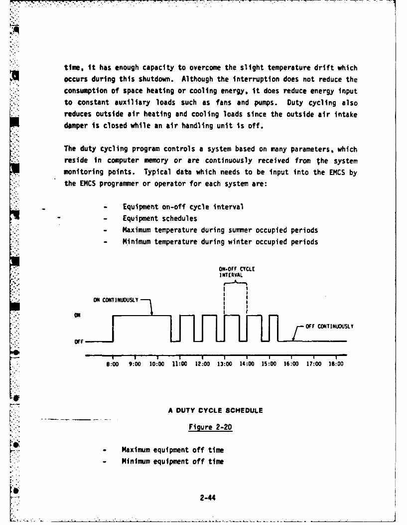
time, it has enough capacity to overcome the slight temperature drift which
occurs during this shutdown. Although the interruption does not reduce the
consumption of space heating or cooling energy, it does reduce energy input
to constant auxiliary loads such as fans and pumps. Duty cycling alsoreduces outside air heating and cooling loads since the outside air intake
damper is closed while an air handling unit is off.
The duty cycling program controls a system based on many parameters, whichreside in computer memory or are continuously received from the system
y7l monitoring points. Typical data which needs to be input into the EMCS by
the EMCS programmer or operator for each system are:
- Equipment on-off cycle interval
- Equipment schedules
- Maximum temperature during summer occupied periods
-.. - Minimum temperature during winter occupied periods
ON-OFF CYCLEINTERVAL
ON CONTINUOUSLL
OFF CONTINUOUSLY
ON H U I I i
8:00 9:00 10:00 11:00 12:00 13:00 14:00 15:00 16:00 17:00 18:00
A DUTY CYCLE SCHEDULE
Figure 2-20
5- - Maximum equipment off time
- Minimum equipment off time
2-44

The specific information and the way it is entered into the computer will
vary depending on the manufacturer of the EMCS central hardware. A sample
duty cycle schedule for an HVAC system is shown in Figure 2-20.
"" The Duty Cycling program works in conjunction with the Scheduled Start/Stop
*and Optimum Start/Stop programs. After the Start/Stop program has started
* a system based on the current occupancy schedule the Duty Cycling program
then controls the system until the end of the occupancy period. The length
of the on-off cycle interval may be different based on time of day, day of
the week, or season. This is determined by the EMCS personnel and is
programmed into computer memory. The on-time duration and off-time
duration may vary within a cycle interval, based on changing space condi-
': tions and requirements of the Demand Limiting program (to be discussed
CYCLES"INTERVAL
- 0--AXIN. OFF TIME
ON AVERAGE LOAD
OFF-
ON HEAVY LOAD
OFF-
ON -LIGHT LOAD),T-- 2OFF -
VARYING ON/OFF TIMES
.Figure 2-21
it 245

next). Off times are automatically decreased if space temperature con-
ditions are not satisfied, or increased If space temperature conditions
remain satisfied.
Varying on/off times are illustrated in Figure 2-21 for different heating
or cooling loads. In addition, the figure indicates the maximum and
minimum off-times which must be established for each system being duty
cycled. Maximum off time prevents loss of control of space conditions.
Minimum off time assures that motors are protected from extreme thermal and
mechanical stress. Frequent cycling produces additional wear on fan belts
and bearings. Electric motors can be damaged by not allowing time for the
motor windings to cool between cycles. Note the increase in motor tem-
perature due to insufficient off-time, illustrated in Figure 2-22. The
solid line represents the instautaneous motor temperature; the dashed line
represents the average motor temperature. Large horsepower motors, above
about 30 hp, are usually not duty cycled because of the increased wear and
possible thermal damage.
MOTOR
IMPROPER SCHEDULE
MOTOR
saw TEMPERATURE
PROPER SCHEDULE•CYCLING MOTOR
4 TEMPERATURE
4THERMAL DAMAGE TO MOTORS DUE TO INSUFFICIENT DUTY CYCLE OFF-TIME
Figure 2-22
2-46

The potential energy savings through duty cycling is proportional to the
length of time the equipment can be turned off, since the electrical energy
consumption is equal to the amount of power required by an electrical load
multiplied by the amount of time the load is operating.
Kilowatt-hours (Kwh) - Kilowatts (Kw) x hours (hr)
For example, if a motor draws 2 Kw and operates 10 hours per day, 5 days a
week, the yearly energy consumption will be
(2 Kw) x (10 hr/day) x (5 day/wk) x (52 wk/yr)
= 5200 Kwh/yr
If the motor'is cycled off for an average of 15 minutes per hour for 10
hours per day the following energy will be saved
(2 Kw) x (15 min ; 60 min/hr) x (10 hr/dy) x (5 dy/wk)
x (52 wk/yr) 1300 Kwh/yr
or a 25% savings.
The EMCS points usually included for implementation of the Duty Cycling
Program on each system are
Monitoring-
(1) Equipment status, differential pressure switch, flow switch,
or auxiliary contacts.
(2) Space dry bulb temperature sensors, at least one per HVAC
system.Control-
(1) Start/stop control signal to interposing relays.
If Scheduled Start/Stop and Optimum Start/Stop are also applied to the same
system, the points are not duplicated. Signals to or from the same field
2-47
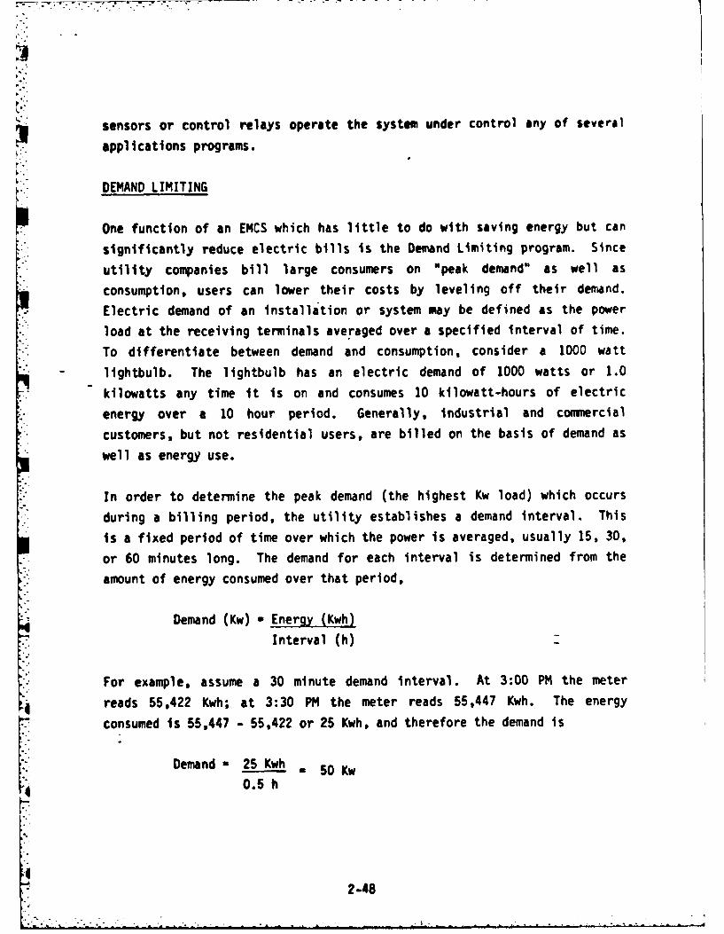
sensors or control relays operate the system under control any of several
applications programs.
DEMAND LIMITING
One function of an EMCS which has little to do with saving energy but can
significantly reduce electric bills is the Demand Limiting program. Since
utility companies bill large consumers on "peak demand" as well as
consumption, users can lower their costs by leveling off their demand.
m' Electric demand of an installation or system may be defined as the power
load at the receiving terminals averaged over a specified interval of time.
- To differentiate between demand and consumption, consider a 1000 watt
S-. lightbulb. The lightbulb has an electric demand of 1000 watts or 1.0
* kilowatts any time it is on and consumes 10 kilowatt-hours of electric
energy over a 10 hour period. Generally, industrial and comnercial
customers, but not residential users, are billed on the basis of demand as
well as energy use.
In order to determine the peak demand (the highest Kw load) which occurs
during a billing period, the utility establishes a demand interval. This
is a fixed period of time over which the power is averaged, usually 15, 30,
or 60 minutes long. The demand for each interval is determined from the
, amount of energy consumed over that period,
Demand (Kw) Energy (Kwh)
Interval (h)
* For example, assume a 30 minute demand interval. At 3:00 PM the meter
reads 55,422 Kwh; at 3:30 PM the meter reads 55,447 Kwh. The energy
consumed is 55,447 - 55,422 or 25 Kwh, and therefore the demand is
Demand 25 Kwh"- - 50 Kw
2-48
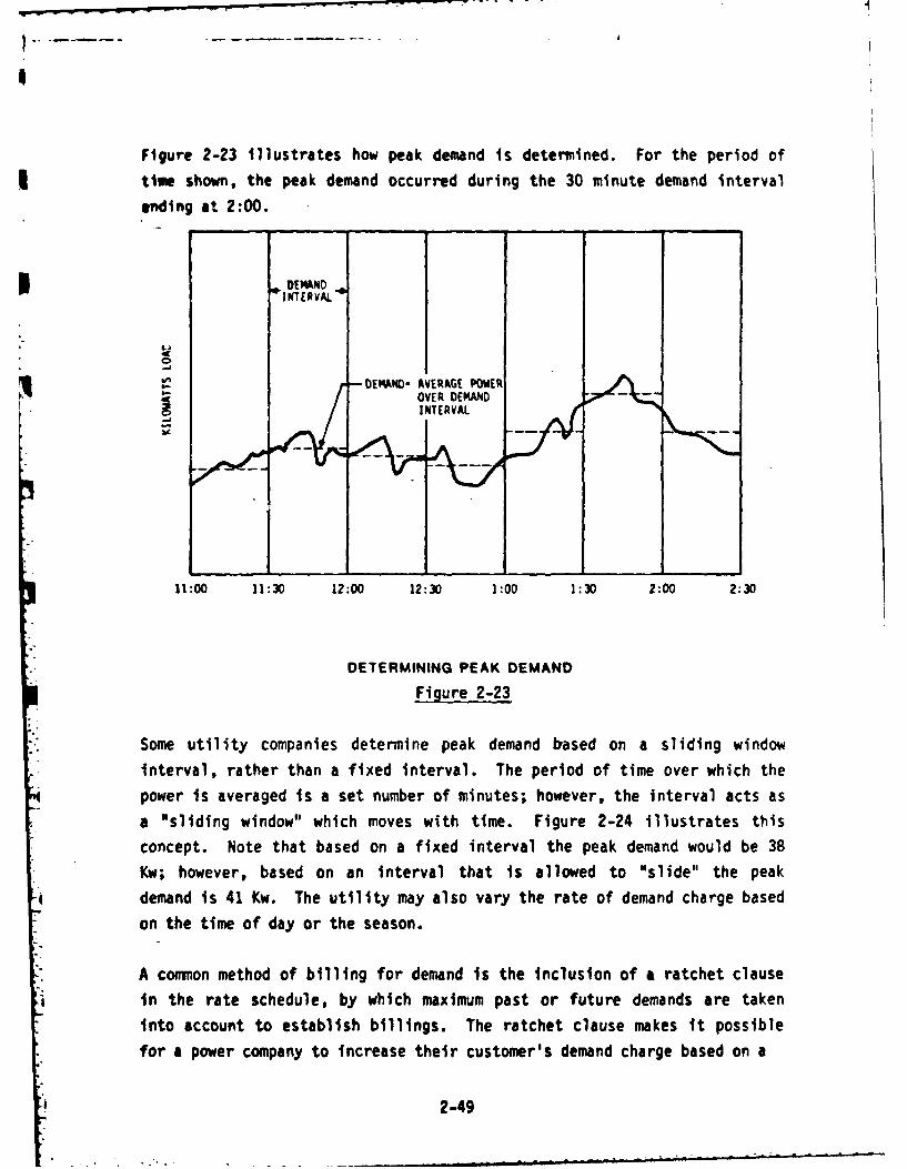
Figure 2-23 Illustrates how peak demand is determined. For the period of
time shown, the peak demand occurred during the 30 minute demand interval
ending at 2:00.
DEMANDINTER VAL
DEMAND- AVERAGE POWER
INTERVAL)
11:00 11:30 12:00 12:30 1:00 1:30 2:00 2:30
DETERMINING PEAK DEMAND
Figure 2-23
Some utility companies determine peak demand based on a sliding window
interval, rather than a fixed interval. The period of time over which the
power is averaged is a set number of minutes; however, the interval acts as
a "sliding window" which moves with time. Figure 2-24 illustrates this
concept. Note that based on a fixed interval the peak demand would be 38
Kw; however, based on an interval that is allowed to "slide" the peak
demand is 41 Kw. The utility may also vary the rate of demand charge based
on the time of day or the season.
A common method of billing for demand is the inclusion of a ratchet clause
in the rate schedule, by which maximum past or future demands are taken
into account to establish billings. The ratchet clause makes it possible
for a power company to increase their customer's demand charge based on a
2-49

soso _ SLI !:NG/
40
-D
FIXED0000- INTERVAL
20
10
12:00 12: 15 12:30 12:45 1:00 1:15
SLIDING WINDOW INTERVAL
Figure 2-24
peak value and leave it at the new level for as long as 11 months. For
example, consider a building which sets a demand peak of 3000 Kw in July.
With a 11 month 90% ratchet clause the customer's demand charges will be
based on at least 90% of 3000 Kw or 2700 Kw for the next 11 months. For
example, where the average monthly demand equals 2290 KW:
Annual bill with ratchet clause would be:
(3000 kw x .9) x ($10.00/kw) x (12 mo.) - $324,000
Annual bill without ratchet clause would be:
(2290 kw) x ($10.00/kw) x (12 mo.) $274,800
Additional cost due to ratchet * $49,200
Each utility company has its own method for determining a customer's bill.
In fact each utility probably has several different rate schedules for
2-50

-II
)EiR!EEE. Z Iii I• 1:thIli ii ,|! Iz
!I '|| 1: " '" "" t~
ii 'II !, 1 , J~
Iit
all ll aI Ii t i
o 1 1 -O~ ,.
dir,,, li ,,,,i it
-4 ~i' lj
Figure 2-25
2-51

different types of customers. A sample commercial rate schedule from the
Georgia Power Company is reproduced in Figure 2-25 to show how complex one
can be. In addition to charging for Kw demand and Kwh consumption, bills
my also include charges for fuel adjustment, taxes, low power factor, and
." other riders. It would be useful for the EMCS operator to review a copy of
* the electric rate schedule which applies to their EMCS facility.
The Demand Limiting program prevents unnecessarily high electric peak
demand and corresponding utility costs in installations where demand-
. oriented rate schedules apply. There are many complex schemes for
accomplishing this function. Generally, they all monitor the facility
electric demand continuously. Based on the monitored data, demand pre-
dictions are made by the EMCS. When these predictions exceed preset
limits, certain scheduled electric loads are shut off by the EMCS to reduce
the rate of consumption and the predicted peak demand. Additional loads
are turned off on a priority basis if the demand is not reduced
sufficiently to satisfy the program requirements. Generally, the loads to
be turned off or "shed" are HVAC items. Loads are restarted based on
priority or a rotational scheme as the continually monitored data allows.
The demand prediction method, load shedding scheme, and program inputs
required for a particular EMCS installation depenc on (1) the peculiarities
of the EMCS vendor software, (2) the EMCS design, and (3) the power company
rate schedule.
It should be evident by now, that the Demand Limiting program does not save
energy but reduces the facility electric bills. On a monthly basis, thesavings can be anywhere from $1.00 to $8.00 per kilowatt which is shaved
off the peak demand. The possible reduction of peak demand depends on the
type of loads which are under control of the EMCS, but typically is in therange of 20 to 25% of the total Kw draw of the controlled loads. For the
utility company, the Kw savings translates to a reduction in the need for
new power generating facilities.
2-52

The EMCS points required to implement the Demand Limiting program are
Monitoring-
(1) Equipment status for each piece of equipment thdt may be
shed; differential pressure switch, flow switch, or
auxiliary contacts.
(2) Instantaneous kilowatt measurement for each electric meter.
(3) Start of demand interval signal, one per site.
Control-(1) Start/stop control signal to interposing relays, one for
each piece of equipment that may be shed.
Program parameters which may need to be changed by the EMCS operator or
programmer are
(1) Peak demand limit target
(2) Equipment priority schedule
(3) Length of demand interval
(4) Maximum temperature during sumer occupied periods
(5) Minimum temperature during winter occupied periods
(6) Equipment constraints, such as minimum off-time
The last three items have the same purpose as for the Duty Cycling program,
although the values could be different for the two programs.
The Demand Limiting program is used in conjunction with the Duty Cycling
program to prevent any one load from being cycled on or off during the
wrong time interval or an excessive number of times. The Demand Limiting
program is also used in conjunction with scheduled start/stop, optimum
start/stop, and chiller optimization programs.
DAY/NIGHT SETBACK
Unlike the Scheduled Start/Stop program, Day/Night Setback can be applied
4 to HVAC systems which have no auxiliary fans or pumps, such as steam
2-53
4 " -. . . . . . . " ' - i i l d ~ l m l l i; i"

radiators. By lowering the heating setpolnt from normal winter Inside
design temperature during unoccupied periods, heating energy consumption
can be reduced. The magnitude of savings will be proportional to thenumber of degrees of setback. The program is also applicable to fan
systems which serve critical areas that have a temperature, humidity, orpressure requirement during unoccupied hours. In spaces that require air
conditioning, but can allow a higher setting than the normal summer inside
design temperature, the setpoint can be reset upwards to a temperature
compatible with the special requirements.
OCCUPIED- PERIOD
tT /-- OOCCUPEDtSPACE HRSA
YNGTTEMPERATURE SET BC O ETING
~Figure 2-26
The outside air damper on a fan system Is generally set at a fixed position
or automatically opens and closes due to a control interlock with the fan
2-54
SY TE ,ONL .-. Ia + k li m ,ma. m,.m+ .

starter. When a system continues to run during the unoccupied period,
ventilation normally is not required. As a result energy is consumed
K unnecessarily in the process of heating or cooling the outside air. TheDay/Night Setback program saves additional energy by independently con-
trolling the outside air dampers. The EMCS sends a signal to close the
outside air dampers at the same time that it resets the space temperature
setpoint prior to the unoccupied period.
The EMCS points generally included for each system to implement this
program are
Monitoring-
(1) Equipment status, differential pressure switch, flow switch,
or auxiliary contacts, if applicable.
(2) Outside air intake damper position indicator, one per OA
damper, if applicable.
(3) Space dry bulb temperature sensors, minimum of one per HVAC
system.
Control-
(1) Day/night signal to interposing relays.
(2) Control signal to close outside air damper, one per OA
damper, if applicable.
LIGHTING CONTROL
About 30% of a building's energy is consumed in lighting alone. The goal
• "of lighting control is to allow lights on only when and where they are
, necessary. This is accomplished basically in the same way as Scheduled
* Start/Stop and in conjunction with that program; lights are turned on and
!4 off based on the time of day and the day of the week. A method of over-
riding the programed schedule usually is provided for overtime use of
lighting.
2-55

Additional off commands may be generated at regular Intervals to assure
that lights are off. An alternative to this method is to initiate only the
off function and require that the lights be turned on manually. Emergency
lighting will not be controlled by this program.
EMCS points which are required for implementation of this program are:
Monitoring-
(1) Lighting status, auxiliary contacts, one for each controlled
* lighting zone.Control-
(1) On/off control signal to interposing relays, one for each
- .controlled lighting zone.
The EMCS operator at times may need to adjust the lighting schedules based
on changing occupancy schedules. As with the Scheduled Start/Stop program,
it is important that EMCS personnel maintain good communication with
building supervisors to ensure that the programmed on/off schedules
correspond with building requirements.
ECONOMIZER
In Section 1 of Chapter 1 it was stated that in most commercial buildings
cooling is required year-round in the interior zones. This situation
provides an opportunity for energy savings by using outside air to aid
mechanical refrigeration whenever the outside air is cool enough.
Economizer control is activated whenever the outside air temperature isbelow a set changeover temperature. The changeover point is a design
consideration and will vary according to location. For instance, morehumid climates will require a lower changeover temperatures. Recall that
the air conditioning process consumes energy in the removal of water from
the air as well as lowering the temperature. Therefore humid air,
although at a lower dry bulb temperature than return air could result in an
additional refrigeration load.
2-56

(CAGOVRTMPRTR COT) F)O
Figure 2-27
2-57

.. .: .'". '. 7 F -. > - ~ ~ ..... .-" ".T ' - .- --- " -" - - -
Under economizer control the EMCS will open the outside Air and exhaust air
dampers and-close the return air damper to allow 100% outside air to enter
the air handling system. If a mixture of outside and return air is the
best choice from an energy standpoint, the program will calculate the
desired mixture and adjust the outside air dampers, return air dampers, andexhaust air dampers accordingly. Recall that generally the relative
positions of the outside, exhaust, and return air dampers are interlockedto maintain a constant air flow rate. When the outside air dry bulb tem-
perature is above the changeover temperature, the dampers are positioned to
provide minimum required outside air.
The energy savings potential of the Economizer program is dependent on the
climate of the site as well as the cooling load of the building. Figure
2-28 lists the percentages of cooling energy which can be saved when
economizer cdntrol is applied to a hypothetical fan system. The numbers
are based on a 55°F supply air temperature, 20% minimum outside air, 75°F
* and 50% RH return air, 16 hours a day and 7 days a week operation. The
first column under savings is for the Economizer control, the second is for
Enthalpy control which will be discussed next.
2-58
-. •~

]1
oI
CITY % COOLING SAVINGS
ECONOMIZER ENTHALPY
Atlanta 30 32
Chicago 39 41
Cleveland 40 43
Dallas 25 27
Denver 54 55
Detroit 39 42
Houston 18 19
Indianapolis 35 38
*- Los Angeles 42 44
Miami. 5 6
Milwaukee 44 47
Minneapolis 39 42
New York 44 46
Phoenix 23 24
Portland 65 66
Sacramento 45 46
San Francisco 65 66
Figure 2-28
The EMCS points which are required for each system to implement the
Economizer program are
Monitoring-
(1) Outside air intake damper position indicator.
(2) Outside air dry bulb temperature sensor, one per site.
Control-
r (1) Damper position control signal to local control loop.
- Program parameters which may need to be changed by the EMCS operator are
the changeover dry bulb temperature and minimum outside air damper
position.
2-59

ENTHALPY
. The Enthalpy program has the same function as the Economizer pri-am; that
.- is, to permit use of outside air for cooling. They differ, however, in how
they determine if use of additional outside air will be advantageous.
Either program, but not both, will be applied to a system.
Enthalpy may be defined as a measure of the heat content of a substance and
L is normally designated by the letter "H". For air the total heat content,
or enthalpy, is made up of two components, the sensible heat and the latent
heat of water in the air.
ENTHALPY SENSIBLE HEAT + LATENT HEAT OF
(TOTAL HEAT) OF AIR WATER IN AIR
Dry bulb temperature is a measure of sensible heat in the air. Relative
humidity is a measure of latent heat (moisture) in the air. By measuring
temperature and relative humidity the enthalpy of air can be determined. A
chart illustrating this relationship is called a "psychrometric" chart and
can be seen in the Appendix.
I0
",-6

I T .~
ENTHALPIES (Btu/lb)780, 50% 29.91
73,80%' 32.73620 , 65%/0 23.22
A ENTHALPY ECONOMIZER CONTROL
Fivure 2-29
4 2-61

po- -
To determine the optimum amount of outside air to allow into an air
handling system the Enthalpy program calculates the enthalpy of the outside
" air and the enthalpy of the return air stream. If the enthalpy of the
outside air is less than the enthalpy of the return air, and cooling is
desired, then the outside air and return air dampers air allowed to
modulate, and sufficient outside air is admitted to minimize the cooling
load and maintain required mixed air conditions. If the outside air
enthalpy is greater than return air enthalpy then the program positions theoutside air dampers, return air dampers, and exhaust air dampers to provide
minimum required outside air.
Note in the top example in Figure 2-29 that in spite of the fact that the
dry bulb temperature of the outside air is less than that of the return
air, the enthalpy is not, due to the higher humidity. The program in this
case would maintain minimum outside air damper position. The OAH and RAH
in Figure 2-29 stand for outside air enthalpy and return air enthalpy,
respectively.
There is more potential for energy savings from the Enthalpy program than
the Economizer program due to a more accurate changeover point. Enthalpy
control is more costly to implement, however, due to the addition of
humidity or dewpoint sensors. Comparing the percentage savings of the two
strategies in Figure 2-28, we see that enthalpy control achieves an
additional I to 3% savings over economizer control.
The EMCS points which usually are included for each system to implement the
Enthalpy program are
Monitoring-
(1) Outside air intake damper position indicator.
(2) Return air dry bulb temperature sensor.
(3) Return air relative humidity or dewpoint sensor.
(4) Outside air dry bulb temperature sensor, one per site.
(5) Outside air relative humidity or dewpoint sensor, one per
site.
2-62

Control -
(1) Damper position control signal to local control loop.
VENTILATION AND RECIRCULATION
The Ventilation and Recirculation program, like the Economizer and Enthalpy
programs, reduces energy consumption by controlling outside air dampers.
Required ventilation for conditioned spaces needs to be supplied only when
they are occupied. Many fan systems are required to run continuously
during unoccupied hours to meet 24-hour temperature, humidity, or pressure
requirements. Other air handlers cycle on during unoccupied times to
* maintain a minimum setback temperature. Also, all systems have to be
started before occupancy to bring the space to comfort conditions. In
- these situations the outside air dampers can be closed and 100% return air
recirculated. The result is unnecessary outside air is not heated or
cooled and thus less energy is used by the HVAC equipment. During occupied
*I periods, the outside air, return air, and exhaust air dampers are under
local control. The Ventilation and Recirculation program works in
conjunction with the Economizer or Enthalpy program so that during
*. unoccupied periods when outside air would not impose an additional thermal
* load on the system, but would help condition the space, the outside airdampers are opened.
Heating savings which might be achieved by this program for a 5000 ft 2
electronics lab which requires 68*F, year-round, 24-hours a day are listed
in Figure 2-30 for various locations.
EMCS points usually included for each system to implement the Ventilation
and Recirculation program are
Monitoring-
(1) Outside air damper position indicator.
(2) Outside air dry bulb temperature sensor, one per facility.
Control-
(1) Open/close damper control signal interfaced to local
controls.
2-63
................................

ANNUAL SAVINGS
LOCATION CF OF GAS $
Atlanta 55,700 $287
Chicago 106,050 546
Denver 100,860 520
Los Angeles 16,570 85
Louisville 72,750 375
Ventilation and Recirculation Savings
(5000 ft2 electronics lab, 24-hr operation)
Figure 2-30
HOT DECK/COLD'DECK TEMPERATURE RESET
Most HVAC systems are sized to maintain comfort levels during design
conditions, even though these conditions may only occur a few times a year.
The rest of the time, substantially less heating and cooling output will do
the job. Dual duct and multizone systems are designed so the coil
capacities and the hot and cold deck discharge setpoints will meet the
heating and cooling demands at design conditions. Considerable energy is
wasted at all other times due to the mixing of hot air and cold air to
provide the required temperatures for all the zones.
The objective of the Hot Deck/Cold Deck Temperature Reset Program is to
maintain the minimum temperature difference between the hot and cold supply
ducts consistent with zone demands. The EMCS resets the hot deck discharge
to a temperature just high enough to satisfy the zone needing the most
" heat. Likewise, it resets the cold deck discharge to a temperature just
low enough to satisfy the zone needing the most cooling. The program
. accomplishes this task by sensing the positions of all or the most critical
zone dampers. The hot and cold deck temperatures are adjusted until the
S dampers on one zone provide 100% cold air and the dampers on another zone
. provide 100% hot air. Where humidity control is required, the program will
2-64

prevent the cold deck temperature from exceeding the point at which the
space humidity reaches its maximum setpoint.
Consider the following example of a dual duct system.
50,000 cfm
25,000 cfm flow through hot deck
25,000 cfm flow through cold deck
550F cold deck setting
110 0F hot deck setting
Assume the zone with the highest heating load requires a 107'F supply air
temperature and the zone with the highest cooling load requires a 57°F
supply air temperature. The program would reset the hot deck at 1070 and
the cold deck at 57°F. The resulting savings would be
5- -570 RESET -13S %5BM COLINGS SAVINGS
110 - 107" RESET - 81 MH HEATING SAVINGS(HB.MIXING BOX)
HOT DECK/COLD DECK TEMPERATURE RESET
Figure 2-31
2-65

(25,000 cfm)(1.08 Btu/hr*F-cfm)(110*-107*)
- 81,000 Btu/hr
(25,000 cfm)(4.5 lb/hr-cfm)(0.6 Btu/16=F)(57°-55 °)a 135,000 Btu/hr
The EMCS points which are usually included for each system to which the Hot
Deck/Cold Deck Temperature Reset program is applied are
Moni toring-
(1) Hot deck discharge temperature sensor.
(2) Cold deck discharge temperature sensor.
(3) Space dry bulb temperature sensors, one per zone up to 40%
of the zones.
4-. () Space relative humidity sensor, one per zone requiring
humidity control.
(5) Mixing box damper position indicators or proportional
signal, one per zone.
Control-
(1) Hot deck temperature control point adjustment.
(2) Cold deck temperature control point adjustment.
REHEAT COIL RESET
Terminal reheat systems operate with a constant cold deck discharge
temperature. Air supplied at temperatures below the individual space
temperature requirements is elevated in temperature by reheat coils in
response to signals from individual space thermostats. If every zone is
reheating supply air, the cold deck is too cold and cooling energy, as well
as reheat energy, is being wasted.
The Reheat Coil Reset program reduces energy consumption in a fashion
- similar to the Hot Deck/Cold Deck Temperature Reset program. The program
measures the discharge temperature or the reheat coil valve position of
each zone and selects the reheat zone with the highest cooling demand (the
zone with the least amount of reheat required). The cold supply air
2-66

temperature is set upward until the critical zone no longer needs reheat,
thus minimizing the total reheat energy required. Where humidity control
is required, the program will prevent the cooling coil discharge
temperature from being set higher than the maximum allowable humidity will
allow.
RCI
C C-K
igi
RC
CDJ REETPON
i.CD RESET POINT -C
CD SETPOINT
COLD DECK TEMPERATURE RESET
Figure 2-32
For a reheat system that operates 50 hours per week and for which an
average 50 reset of the cooling coil is achievable, the annual reheat
energy savings would be about 22 cubic feet of gas per cfm. The annual
cooling savings would vary relative to the climate and would range betweer
0.2 and 2.2 kwh per cfm.
The EMCS points which are usually included for each system to which the
Reheat Coil Reset program is applied are
2-67

Monitoring-
(1) Cooling coil discharge temperature sensor.
(2) Reheat coil valve position indicator or proportional signal,
one per zone.
(3) Space dry bulb temperature sensor, one per zone up to 40% of
the zones.
(4) Space relative humidity sensor, one per zone requiring
humidity control.
Control-
(1) Cooling coil discharge temperature control point adjustment.
BOILER OPTIMIZATION
- Most boilers achieve maximum efficiency only when running at their rated
output. In most cases, however, full boiler capacity is seldom required
because the heating load is 60% or less than full load, 90% of the time
(see Figure 2-33).
100% Full Heating Load.:i'-" ' 6 Days
"-. ,, x SO0% Heating Load0m o "' 20 Days 60% Heating Load
" 2-1" 124 Days
": 5001r \ 40"/.Hooting Lod
Z .::_ 20%/ Heating":W Load.,.- -''' 42 Daoys
:I;50 I100 150 200 250
!:'-"-HEATING DAYS
': TYPICAL HEATING LOAD DISTRIBUTION
(250-DAY SEASON IN 6000 DEGREE ZONE)
"-:: Figure 2-33
j2-68
-... -,

Given this situation, single large capacity boilers operate intermittently
for the major part of the heating season. Although high-low firing
- capabilities may reduce cycling, the boilers can reach their design
*efficiency only for short periods, resulting in low seasonal efficiencies
(see Figure 2-34). Seasonal efficiency can be improved with a multiple
boiler plant. Each boiler is fired near its capacity as much as possible.
As the heating load increases, the separate boilers are brought on line in
sequence until the load is satisfied.
80%S10% of Heating
U Season in thisW 5 Range
UW 90% of Heating
70% Season in this____________________ Range
25%. 50%' 75% 100%PERCENT TIME ON LINE
EFFECT OF CYCLING TO MEET PART LOADS
Figure 2-34
The Boiler Optimization program may be implemented for multiple boiler
, plants with either hot water or steam boilers to effect the above described
savings. By monitoring fuel i, ijt as a function of the output, the EMCS
develops profiles for each of the units in a central plant. Based on the
operating history indicated in the efficiency"profiles, the boiler or
combination of boilers with the highest efficiency at a given heating load
* can be selected. Boilers may be started manually by a boiler operator or
automatically by the EMCS depending on facility requirements. The seasonal
efficiency of the central heating plant can be improved by 5 to 10% with
implementation of this program.
2-69

The EMCS points which may be included for implementation of the Boiler
Optimization program are
Monitoring-
(1) Boiler status (auxiliary contacts), one per boiler alarm
point.
(2) Flame status, one per boiler.
(3) Steam supply pressure sensor, one per steam boiler.
(4) Steam or hot water supply temperature sensor, one per
boiler.
(5) Steam or hot water flow sensor, one per boiler.
(6) Fuel flow sensor, one per boiler.
(7) Fuel temperature sensor, one per boiler.
(8) Feed water flow sensor, one per boiler.
(9) Feed water temperature sensor, one per boiler.
(10) Oil temperature sensor, one per boiler if oil is heated.
(11) Hot water return water temperature sensor, one per hot water
boiler.
(12) Boiler pressure, one per hot water boiler.
(13) Boiler water level sensor, one per hot water boiler.
(14) Flue gas analyzer, one per boiler.
(15) Common steam supply pressure sensor, one per steam plant.
(16) Common steam or hot water supply temperature sensor, one per
heating plant.
(17) Common condensate return total flow sensor, one per steam
plant.
(18) Common condensate or hot water return temperature sensor,
one per heating plant.
(19) Total hot water flow sensor, one per hot water plant.
Control-
(1) Start/stop automatic control signal to interposing relays or
start/stop signal to boiler operator for manual control, one
for each boiler.
2-70

REMOTE BOILER MONITORING AND SUPERVISION
The cost of fossil fuels for heating far outweighs cooling costs for
buildings in the United States. So it is important to get the most heat
out of each gallon, pound or cubic foot of fuel possible. All boilers,
regardless of size, should have routine measurements of stack temperatures
. avid flue gas analysis at frequent intervals. Based on monitored data the
air-fuel mixture should be adjusted to maximize the combustion efficiency.
Figure 2-35 displays the relationship of flue gas composition, stack
temperature, and boiler efficiency. The ideal oxygen (02) concentration in
flue gas is between 3 and 5%. Lower than that is impractical and unsafe,
due to increased production of pollutants.
Proper maintenance of fuel burners and heat transfer surfaces also is
* required to maintain high boiler efficiencies. Fuel burning equipment
allowed to become dirty and out of adjustment becomes increasingly
inefficient with continued usage. Likewise, both fire-side and water-side
.r heat transfer surfaces become less and less effective if allowed to become
*. fouled by products of combustion, scaling, and other impurities. All heat
not properly transferred is discharged through the stack. Boilers that are
regularly checked, cleaned, and adjusted can have efficiencies 3 tO 5%
higher than poorly maintained units.
*? The primary purpose of the Remote Boiler Monitoring and Supervision program
is to aid in the maintenance of facility boilers. The savings are
* generated from a reduction of boiler-operator labor hours. A small savings
in energy is also possible, depending on how well maintained the boilers
were previous to installation of the EMCS. The reduction of boiler
4 operator labor hours is governed by criteria which varies depending on
local codes regulations. These should be investigated before investing in
EMCS Boiler Monitoring.
*i 2-71

The EMCS points required for Implementation of this program are included in
those listed for Boiler Optimization, with the possible addition of a stack
temperature monitoring point. The two programs operate in conjunction with
one another.
2
I
.1.
°4
~2.72

g 300
IiISMds
675
0 -
7 0 3 10 1T11.
________ p %4 I i II a I 'iNO.6011 ~~OTA AI0R'1 1 4 51
2-ur 23
2-7b-1670 9 0 Ii.

HOT WATER OUTSIDE AIR RESET
Hot water heating systems, whether the hot water is supplied by a boiler or
a converter, are designed to supply the heating requirements for the system
at outdoor design temperatures. Frequently, depending on the specific
system design, the hot water supply temperature can be reduced based on the
heating requirements for the facility. For most facilities, a reduction in
heating requirements is directly related to an increase in outdoor ambient
temperature. Where applicable, the temperature controller for the hotwater supply is reset by the EMCS on a predetermined schedule as a function
of outdoor temperature.
140
* . 130
120
110
~100
4O
, I I I I I I I I I
-20 -10 0 10 20 30 40 50 60 70 80
OUTSIDE AIR TENPERATURE (F)
TYPICAL HOT WATER OUTSIDE AIR RESET SCHEDULE
r.-- Figure 2-36
An example of a hot water outside air reset schedule is:
OA HW
OF 140OF70F 800F
ILI 2-74
.

Below 0* outside air temperature the hot water is at 1400. Above 700
outside air temperature the hot water is at BO°. Between O°F and 70°F the
hot water temperature varies linearly. That is, at 350F the hot water will
be reset at 1100. (See Figure 2-36) Linear reset schedules, such as the
example, are most common, although a different type schedule may be
encountered at some facilities.
Energy savings is achieved by the Hot Water Outside Air Reset due primarily
to a reduction in heat losses from pipes and heating system equipment.
Figure 2-37 illustrates the effect of the water temperature on heat lossfrom indoor piping. The graph is based on pipes with i insulation. Note
the greater rate of heat loss at higher water temperatures. The hot water
reset also meets heating demands in uncontrolled hot water radiator zones
more efficiently.
250
PIPE SIZE 2"
200
o. 111O
:IS
I00, 120" 140" 1IO 160°
i:MD HOY AER TEMPERATURE
iii
b.. EFFECT OF NOT WATER TEMPERATURE ON HEAT LOSS FROM PIPES
Figure 2-37
-2-75

*. The EMCS points which are required to implement this program are
Monitoring-
- (1) Hot water supply temperature sensor, one per boiler or
converter.
. (2) Outside dry bulb temperature sensor, one per site.
Control-
(1) Hot water supply temperature control point adjustment, one
per boiler or converter.
At new EMCS installation, it may be necessary to adjust the reset schedule
during the first heating season.
* CHILLER OPTIMIZATION
*l The Chiller Optimization program works on the same principal as the Boiler
Optimization program. A chiller is designed to operate most efficiently at
a particular load condition, and efficiency drops off at loads
significantly higher or lower than this. See the typical chiller load
profile in Figure 2-38. In order to save energy, it is desirable to select
the optimum combination of chillers needed at various partial load
conditions. The chiller combination selection process should assume that
the chillers that are in operation are running within their most efficient
ranges.
The Chiller Optimization program is applied to chilled water plants with
multiple chillers. Based on chiller operating data and the energy input
requirements obtained from the manufacturer for each chiller, the program
selects the chiller or chillers that meet the load with a minimum of energy
consumption. When a chiller or chillers are started, chiller capacity is
limited (prevented from going full load) for a predetermined period to
allow the system to stabilize in order to determine the actual cooling
load. Chillers may be started automatically by the EMCS or manually by the
chiller operator depending on site requirements.
.2
2-76

lnI i i i
0 20 40 60 80 100
% LOAD
CHILLER EFFICIENCY VS. LOAD
Figure 2-38
Data gathered from this program may also be used for maintenance management
of the chiller plant. Comparison of equipment characteristics to the
actual operating chiller characteristics makes it possible to determine
when heat transfer surfaces need cleaning, and thus help maintain high
efficiency.
EMCS points which may be included, although all are not required in every
case, to implement the Chiller Optimization program are
*i Monitoring-
(1) Chiller status, auxiliary contacts, one per chiller.
(2) Chilled water supply temperature sensor, one per chiller.
(3) Chilled water return temperature sensor, one per chiller.
W. (4) Chilled water flow sensor, one per each chiller with
variable flow.
(5) Leaving condenser water temperature sensor, one per chiller.
2-77

(6) Condenser water flow sensor, one per chiller, for variable
flow condenser system only.
(7) Instantaneous KW to chiller, one per chiller.
(8) Instantaneous KW to chilled water pump, one per CW pump, if
variable.
(9) Instantaneous KW to condenser water pump, one per condensate
water pump, if variable.
(10) Instantaneous KW to cooling tower fan, one per cooling tower
fan, if variable.
(11) Common chilled ,water supply temperature sensor, one per
(12)'chilled water plant..
(12) Common chilled water return temperature sensor, one per
chilled water plant.
(13) Total chilled water flow sensor, one per chilled water
plant.
(14) Chilled water pump status, differential pressure switch or
flow switch, one per chilled water pump.
(15) Condenser water pump status, differential pressure switch or
flow switch, one per condenser water pump.
(16) Cooling tower fan status, differential pressure switch, zero
speed switch, or flow switch, one per cooling tower fan.
Control -
(1) Start/stop control signal to interposing relays or
start/stop signal to chiller operator for manual control,
one for each chiller, chilled water pump, condensate water
pump, cooling tower fan, as required.
CHILLER WATER TEMPERATURE RESET
The energy required to generate chilled water in a reciprocating or
centrifugal refrigeration machine is a function of a number of parametersincluding the temperature of the chilled water leaving the machine. Lessrefrigerant needs to be compressed by the compressor at higher chilled
water temperatures resulting in lower energy input per ton of
refrigeration. Normally, chillers are controlled to maintain a constant
chilled water supply temperature of 450F. Because chiller capacities are
2-78

. selected for peak design times, in the absence of strict humidity control
requirements, chilled water temperatures can, be elevated during most
operating hours without any loss of human comfort.
The Chiller Water Temperature Reset program resets the chilled water
temperature controller to the highest temperature which will maintain
required space temperature and humidity conditions. This is determined by
monitoring space temperatures or more accurately by monitoring positions of
the chilled water valves on various cooling systems. The desired state has
been attained when one valve is in the maximum open position.
The energy which can be saved from implementation of this program varies
with climate and building conditions. Improvement in chiller efficiency is
about 1.5% for each 1°F average increase in chilled water temperature as
displayed in Figure 2-39 for the different types of chillers.
25 -SCREW COMPRESSOR
ID s A
m REC IPROCATINMG
ASORPT lON
S
5010
INCREASE IN CHILLED WATER SUPPLY TEMPERATURE (*F)
EFFECT OF CHW TEMPERATURE ON COP
Figure 2-39
2-79

EMCS points required to implement the Chilled Water Temperature Reset
program are
Monitoring-
(1) Chilled water valve position, analog position indicator, or
fully open indicator on valve stem, one per air conditioning
chilled water valve.
(2) Space dry bulb temperature sensor, one per zone.
(3) Chilled water supply temperature sensor.
(4) Space relative humidity sensor, one per zone where required.
Control-
(1) Chilled water supply temperature control point adjustment,
one per chiller.
CONDENSER WATER TEMPERATURE RESET
Another parameter affecting the energy input to a refrigeration system is
the temperature of the condenser water entering the machine.
Conventionally, heat rejection equipment is designed to produce a specified
condenser water temperature, usually 850, at peak wet bulb temperatures.
In many instances, automatic controls are provided to maintain that
temperature at conditions other than peak design. To optimize the
performance of the condenser water system, however, this system can bereset when outdoor wet bulb temperatures will produce lower condenser water
temperatures. The lower condenser water temperature subcools the liquid
refrigerant in the condenser, below the required saturation temperature.
As a result, the refrigerating effect (the amount of heat each pound ofrefrigerant can absorb) is increased and the compressor has less work to
do.
A cooling tower dissipates heat from the chiller primarily because of thelatent heat carried off by evaporating water. The condenser water cannot
be cooled below outside air wet bulb temperature because no further
evaporation will take place at that point. This places a lower limit onthe condenser water temperature. A margin of several degrees is necessary
for efficient evaporation. Cooling the condenser water down to this
* 2-80
• ii

K -
optimum value may require running the cooling tower fans more, but this
consumes far less energy than running the chiller compressor.
The Condenser Water Temperature Reset program can save energy when applied
to water cooled chillers. The program determines the optimum condenser
water temperature based on the outside wet bulb temperature, which is
calculated from measurement of outdoor dry bulb temperature and outdoor
relative humidity. Manufacturer's requirements are also considered in
*T establishing an acceptable condenser water temperature range. Savings from
implementation of the program ore in the range of 1% efficiency increase
per 1°F decrease in condenser water temperature. The graph in Figure 2-40
compares the effect of condenser water temperature on COP for different
types of chillers.
so
SCREW COMPRESSOR
40
RECIPROCATINGS 30
ABSORPTION
020, ISS 00
DECREASE IN CONDENSER WATER TEMPERATURE ("F)
EFFECT OF CONDENSER WATER TEMPERATURE ON COP
Figure 2-40
EMCS points which are required to implement the Condenser Water Reset
program are
2-81

Monitoring-
(1) Condenser water supply temperature sensor, one per
condenser.
(2) Outside air dry bulb temperature sensor, one per site.
(3) Outside air relative humidity sensor, one per site.
Control-p (1) Condenser water supply temperature control point adjustment,
one per condenser.
CHILLER DEMAND LIMIT
* Chillers represent a large portion of demand for a facility, and therefore
: provide a large potential for demand limiting. The Chiller Demand Limit
program is applicable to large centrifugal water chillers, which should not
be completely shutdown for demand control. Starting and stopping of the
*, large compressor motors is hard on the machinery. Generally, the off-time
-' for these chillers is limited by a safety delay timer, thus limiting the
* potential for EMCS start/stop control.
" Centrifugal water chillers are normally factory equipped with an adjustable
- control system which limits the maximum available cooling capacity; thus,the power the machine can use. The method of accomplishing this function
varies with the manufacturer of the chiller. An interface between the FID
and the chiller controls allows the EMCS to reduce the maximum available
cooling capacity in several fixed steps in a demand limiting situation,
thereby reducing the electric demand without completely shutting down the
chiller.
To accomplish this task, the EMCS determines the chiller percent capacity
by monitoring the chiller current input. When the chiller is selected for
*demand limiting, a single step signal is transmitted, reducing the chiller
* limit adjustment by a fixed amount. The chiller demand limit adjustment is
* performed by shunting out taps of transformers in the control circuit or by
1 resetting the control air pressure to the chiller compressor vane operator.-As further need arises, additional stop signals are transmitted until the
demand limiting situation is corrected.
2-82
............ .. *.....

- -.
The chiller manufacturer's recommended minimum cooling capacity limit is
incorporated into the program logic. Incorrect control can cause the
refrigeration machine to operate in a surge condition, potentially causing
it considerable damage. In general, surges occur in chillers at loads less
than 20% of the rated capacity.
EMCS points which are required to implement the Chiller Demand Limit
program are
Monitoring-
(1) Chiller current monitor, one per chiller.
Control-
(1) Step control signal, one per step per chiller.
(2) Or, analog control signal, one per 'chiller or as required by
controls interface.
APPLICATIONS SOFTWARE DATA
The implementation of any of the above described applications programs
requires the EMCS be provided with data which defines how those programs
should control a particular HVAC system. For example, controlling an air
handler with the scheduled start/stop program required definition of what
start and stop times are desired for each different day type. These
decisions must be made by the personnel who are responsible for HVAC system
operation. In an existing EMCS, the EMCS operator enters the data into the
EMCS. In an EMCS under construction, the EMCS contractor is required to
enter the data into the system, but the base operating personnel must
decide what that data is and provide it to the contractor. Normally the
contractor will provide forms which are filled out and returned to him for
entry into the system. The exact format and quantity of the data varies
widely depending on the particular EMCS being installed. The Tri-Service
* EMCS guide specifications generally list the data required to run each
application program. An example of the data required by the guide
4 specification for the optimum start-stop program is included in Figure
2-41.
2-83

Excerpt from CEGS 13947 (October 1982)U14.16 Optimum Start-Stop Program: Provide software to start and stop
equipment on a sliding schedule based on indoor and outdoor air conditions.
The program shall automatically evaluate the thermal inertia of the
structure, the capacity of the HVAC system to either increase or reduce
space temperatures, indoor and OA conditions using the prediction software
to determine the minimum time of HVAC system operation needed to satisfy
the space environmental requirements at the start of the occupied cycle,
and determines the earliest time for stopping equipment at the day's end.
The program shall monitor the controlled equipment status to verify that
the start or stop command has been carried out, and provide the operator
with an alarm when the equipment does not start or stop, fails, or is
localled started or stopped. The optimum start-stop program shall operate
in conjunction and be coordinated with the scheduled start-stop, day-night
setback, and ventilation-recirculation programs.
14.16.1 Program Inputs:
a. Day of week.
b. Time of day.
c. Summer or winter operation.
d. Equipment schedules.
e. Equipment status.
f. Building occupancy schedule.
g. Space temperature(s).
h. Building thermal inertia coefficient.
i. HVAC system cooling capacity.
J. HVAC system heating capacity.
k. OA temperature.
1. OA relative humidity.
Sm. Chilled water supply temperature.
n. Hot water or steam temperature.
o. Required space temperature at occupancy.
p. Equipment constraints.
,* 14.16.2 Program Outputs:
a. Start signal.
b. Stop signal.
Figure 2-41
2-84

CHAPTER 3
SYSTEM OPERATION
SECTION 1. TREND LOGS AND REPORTS
Trend logs and reports are useful in maintaining energy efficient operation
of the equipment under supervision of the EMCS and as maintenance
management tools. Samples are included in Appendix B. Although the report
titles may differ, standard reports which are available from most EMCS
systems are as follows:
The Electrical Power Utilization Summary (page B-2) provides a record of
electrical energy consumption on a daily and monthly basis. The operator
may select any meter, combination of meters, or all meters which are
connected to the EMCS for output into the report. For each selected meter,
the report will include the total daily consumption, the total monthly
consumption, the demand interval peak for the month and day, time of
occurrence, and the consumption over each demand interval.
The Energy Utilization Summary (page B-3) provides a record of total energy
consumption for a point, a system, a building, an area, or the entire EMCS
installation, as selected by the EMCS operator. For each item, the report
will include the beginning and ending dates and times, the total energy
usage for the current and previous day, the total energy usage for the
current and previous month, the maximum rate of consumption for the current
and previous day, the maximum rate of consumption for the current and
previous month, the outside air temperature, and the outside air relative
humidity or dewpoint. The energy utilization is calculated by the EMCS
based on equipment parameters such as motor rated kilowatts, measured data
3-1
. -. . - • - :. . . , • : : "• " : : ' .- . - .- -r- .,&w w . a - .'. -- -
m ...

such as fuel flow, and equipment run-time. The data generally is displayed
in BTU units.
The Alarm Summary (page B-4) lists all outstanding alarms by class.
The Lockout Summary (page B-5) lists all points which are currently
disabled.
The Analog Limit Summary (page B-6) lists a point's analog value, units,high and low limits, and limit differentials for all analog points, all
- analog points within a building, or all analog points for a system, as
selected by the operator.
Run-Time Reports (page B-7) list the accumulated run-time of individual
pieces of equipment, that is, the total hours and minutes that an item has
been "on" during a stated period of time. The operator is able to select
subsets of equipment for a particular report, such as an individual piece
of equipment, by equipment type (all air handlers), by equipment size (all
motors over 20 hp), or equipment by physical grouping. If desired, the
totalized run-time can be automatically reset to zero upon generation of a
report. This report is particularly useful as a tool for maintenancemanagement. Routine maintenance tasks can be scheduled based on total
run-time. In fact, the EMCS can provide reports on equipment which hasreached a target run-time specified by a maintenance schedule. (See page
B-29). Run-time can also be used to evaluate the life expectancy of
equipment components.
Cooling Tower Profiles (page B-8) provide data on cooling tower operation.The report lists the total daily and monthly on-time for each fan, thenumber of on and off transitions for each fan, the maximum and minimum
4daily condenser water temperature at the time the tower was turned on, and
the maximum and minimum daily condenser water temperatures for the current
month.
3-2

The Electrical Peak Demand Prediction Report (page B-9), which is based on
the demand limiting program, includes the demand peak target, the actual
peak and predicted peak for each demand interval for that day, and the
predicted demand for the next demand interval. This report can be used to
evaluate the demand limiting program and help determine strategy for
changing the demand target or load shedding priorities.
The Chiller Utilization Summary (page B-10) summarizes chiller operations
on a daily and monthly basis. It includes the daily electric consumption
in KWH and the corresponding effective cooling in BTU/Hr for each of at
least ten (10) discrete loading levels, the daily average of all the
levels, the monthly average of these values for each level, and the total
on-time for each level for the current month. This report is useful in
developing chiller profiles and analyzing the effect of chilled water and
condenser water reset strategies. An example of a graphed chiller profile
showing the relationship of energy input to cooling load is shown in Figure
3-1.
1000 80
a 60.
'-.T 40
20 , 40 60 50 100
S FULL LOAD
KW INPUT VERSUS LOAD CAPACITY
Figure 3-1
3-3
-
I
.- 7
The Optimum Start-Stop Report (page B-11) lists all systems and buildingsnot achieving occupancy temperature within twenty (20) minutes of the
designated time. The report can help the operator determine if optimum-* start-stop program parameters should be adjusted.
The Out-of-Service Report (page B-12) lists the devices or points which are
out of service for each item of central hardware and each data transmission
link, FID, HUX, or IMUX.
- . All Points Summary (pages B-13 to B-15) lists the current status of all the
points in the EMCS.
The EMCS is capable of generating a wide variety of logs and reports inaddition to the above standard reports. Any statistical and variable data
values or sets of parameters defined in the data base, calculated using the
data base, or stored as historical data may be printed in a report. The
operator or prograniner may assign the parameters to be used in a customreport and designate the output format. The operator also has the option
of specifying reports that are to be automatically displayed. The operatordesignates the time the initial report is to be generated, the interval of
time between subsequent reports, and the output device on which they are tobe printed or displayed. Samples of miscellaneous reports are shown on
pages B-16 to B-24.
Log trends are a type of report which list a sampling of a defined
parameter or parameters at a selected time interval, such as every fifteen
(15) minutes, for a designated period of time. The kinds of data for which
a log trend. is useful are power consumption, power demand, and
temperatures. Similarly, equipment profiles may be reported as acorrelation of two variables. For instance, the incremental fuel
consumption of a boiler versus the average outside air temperature over a
given time interval can be recorded. The log trends can be graphed for
3-4
i4 . ., " "-- ., .. . . . : - . -. . . : - .. - . . - .- -. : . . .. , . . ,

easy visual interpretation of the data. See the samples pages B-25 to
B-28.
In addition to run-time reports, other report formats can be developed for
use in maintenance management. Maintenance work orders, such as the one on
* page B-29, can be automatically generated based on equipment run-time
totals. Pages B-30 through B-32 are examples of reports of maintenance
- shop inventory information. Some facilities use the EMCS to keep track of
all repairs and maintenance to facility equipment.
It is important to understand that some reports are available on demand
while others require that data to be used in them be defined and stored by
the EMCS prior to output of the report. Reports available on operator
command use the current status or value of points in the system. Reports
which include historical data (such as number of hours of air handling unit
operation) can only be obtained if at some previous point in time the EMCS
-." operator has commanded the EMCS to store and accumulate the data necessary
* for that report. Figure 3-2 lists the reports discussed in this Section
according to type.
It is recommended that in addition to regular daily and monthly generation
* of system performance reports the operator keep a written log of actions
taken during a work shift. An existing EMCS installation geneially will
* have a procedure for documenting daily occurrences. Items that should be
entered in the log, although not all inclusive, are:
1. Incoming telephone calls from occupants of buildings under
control of the EMCS. The time of the call and the nature of the
request or complaint should be recorded.
2. Modification of program or system parameters, such as revised
temperature setpoints or occupancy schedules.
3-5
i"A

* .. . .
"3. Routine maintenance on MCR equipment such as a change of theribbon on a printer or a call to the service contractor to clean
1 the heads on the disk drive.
4. Date, time, and service done during a service call.
~5. EMCS error messages which occur.
3.-
" 3-6

REPORTS AVAILABLE ON DEMAND
Report Example Page No.
Alarm Summary B-4
Lockout Summary B-5
Analog Limit Summary B-6
Out-of-Service Report B-12
All Points Summary B-13
REPORTS REQUIRING PREVIOUS DEFINITION
FOR EMCS DATA RECORDING
Report Example Page No.
Electrical Power Utilization Summary B-2
Energy Utilization Summary B-3
Run Time Reports B-7
Cooling Tower Profiles B-8
Electrical Peak Demand Prediction Program B-9
Chiller Utilization Summary B-10
Optimum Start-Stop Report B-i
*,
Figure 3-2
3-7

SECTION 2. ALARMS
As well as automatically controlling HVAC equipment for minimum energy use,
* the EMCS monitors the equipment to detect any malfunctions. For example,
- high chilled water temperature may be indication of a chiller malfunction.
The malfunctions are indicated by alarm messages that are displayed on the
operator console or alarm printer. The message identifies the alarm
condition, the time of occurrence, the alarm device or sensor type, the
current value or status of the measured variable, and in the case of an
- analog point, the value of the alarm limit which was exceeded. Some EMCS
operator consoles also indicate an alarm with an audible beeping tone or a
blinking area on the screen. The operator can call up secondary messages
which provide further information, such as telephone numbers of people who
should be notified of the alarm condition. The alarm messages may be
edited by the EMCS operator. The secondary alarm message shown in Figure
3-3 provides the operator with a scheme for diagnosing the cause of an
alarm.
SUPPLEMENTARY ALARM SUMMARY REQUESTED BY: 0 0 4/24/198019:27:20
1 CHECK BOILER FUNCTION
2 CHECK COOLING COIL FUNCTION
3 SUPPLY FAN NOT OPERABLE, CHECK H-O-A SWITCH
4 CHECK AHU-1 COLD DUCT TEMP AND CHILLER FLOW
5 CHECK CONDENSER PUMP
6 CHECK COOLING TOWER FAN
7 CHECK CHILLER STATUS
8 CHECK CHILLER WATER SUPPLY PUMP
9 CHECK ENTHALPY SWITCHOVER
Figure 3-3
3-8
"*" . 2 .

Alarms fall in three classes, as designated during data base generationprior to EMCS start-up. Class 1 alarms are printed at the time they occur
and again when the condition returns to normal. Class 2 alarms are printed
* and indicated with an audible alarm at the time they occur and are printed
when the condition returns to normal. Class 3 alarms are printed andindicated with an audible alarm both at the time of occurrence and whenconditions return to normal. The audible alarms are terminated when theoperator acknowledges the alarm or return to normal condition, normally by
pushing a button on the console. All the alarms are printed on the alarm
* printer; Class 2 and Class 3 alarms are also displayed on the operator's-console.
Alarms may also be classified as either digital alarms or analog alarms.Digital alarms are a result of a signal from a digital monitoring point,such as a tripped differential pressure switch which is monitoring thestatus of a supply air fan. The differential pressure switch senses thepressure upstream and downstream of a fan. When the difference between the
pressures is not above a minimum value an electric contact closes and
signals the FID and central computer, indicating that the fan is notoperating. In this example, the alarm point wou'ld be interlocked with the
start/stop control software so that the alarm is printed only if the fan is
scheduled to be on at that time.
Analog sensor readings are compared to predefined high and low limits,resulting in an analog alarm condition if the value falls outside theestablished operating range. High and low limits are assigned to each
analog point in a system. Each high and low limit has an associated uniquelimit differential, specifying the amount by which a variable must returninto the proper operating range before being' displayed as returned tonormal. The operator can enter or change all alarm limits and
differentials in units of the measured variable from the operator console.
Analog points may have more than one set of alarm limits, which
automatically change based on time scheduled operations. For example, the
3-9

* high and low limits for a space temperature in the heating mode might be70*F and 65*F during occupied periods. and 900F and 50*F during unoccupied
S piriods. In control point adjustment applications, the high and low limitsare defined based on a deviation from the setpoint. For example, thechilled water supply temperature will have "sliding" limits when the
chiller water reset applications program is applied to the chiller. If thedeviation from setpoint is ±30F'and the setpoint established by the programis 48OF then a measured value of 44*F will cause an alarm condition.
- In addition to alarms associated with field monitoring points, alarms may*be generated as a result of problems in the EMCS hardware. Such alarm
* conditions are a point not responding to a commnand, point change of statewithout commrand, a field panel not responding, data transmission high error
* rate, real timeclock error, intrusion alarm, and FID failure.
Associated with some alarms is a correlated alarm report as shown in Figure* 3-4, which can be called up by the operator when the alarm condition
CORRELATED ALARM REPORTBLDG-12-CV-1-HWS TEMP IN ALARM
3/15/83 9:07:18
LOW AT 105.90F SETPOINT =114.7LIMITS: LO =111.7* HI =117.70
POINT CURRENT ENG ALARMUSER/ENGLISH NAME DESCRIPTION STATUS/VALUE UNITS STATUS
BLDG 12 CONVi PUMP PUMP ON N RML
BLDG 12 CONVl VALVE VALVE POS 55 % OPEN NRML
BLDG 12 BLR STEAM PRESSURE 5.3 PSIG NRML
BLDG 12 BLR STAAMTUSP ON O NRML
BLDG 12 BLR STEAMTP 227N NRML
Figure 3-4
3-10

',
occurs. The purpose of the report is to display the current status of each
parameter which is dependent on the alarmed point. This information canhelp the operator diagnose the possible cause of the alarm condition and
determine the proper steps to be taken in response.
Diagnosing the cause of an alarm and determining the corrective actionswhich are necessary is not a cut and dried procedure. The EMCS operator
needs to make judgment decisions that will become easier with experience.
No concrete guidelines are available, but some general comments are in
order.
Some alarms recur frequently, and may even become annoying to the operator.
This happens most often with temperature points which are out of range.
The first thing to look for is a malfunction somewhere in the HVAC
equipment. For example, consider a space temperature sensor which
repeatedly exceeds the high alarm limit. The temperature is only slightly
out of range and returns to normal after an hour or two. If many other
space temperatures in the same building are over the high alarm limit then
the problem probably lies with the chiller or chilled water distribution
systems.
If the problem is at the air handler it could be a dirty filter which would
cut down the air flow and therefore, the cooling capacity of the-unit. If
the system also has an EMCS differential pressure.sensor across the filter
and It is also in an alarm condition then there is a good chance that a
dirty filter is the cause of the temperature alarm. In most cases,
however, there will be no filter alarm point. Another possible problem is
a dirty cooling coil which will lower the heat transfer rate of the coil,
and therefore the cooling capacity of the unit. The outside air damper
linkages or motors may be broken resulting In restricted air flow or excess
4outside air. These are maintenance problems that require field inspection
of the air handling unit to pinpoint the cause of the alarm.
3-11

Many malfunctions in the local control loop could cause the hypothetical
temperature alarm. The room thermostat could be malfunctioning, out of
calibration, or simply set at a temperature above the EMCS high alarm limit
for the space temperature. There could be an air leak in the local
pneumatic control system so that control devices receive low pressure
signals. The cooling coil control valve could be restricted from opening
to its fully open position or have some other problem. Another item to
consider is a malfunctioning EMCS sensor or one which needs calibrating.
These control system malfunctions would also require a field inspection and
repair to alleviate the high space temperature.
If field checkout eliminates the possibility of equipment malfunction, then
the problem may be that the design capacity of the equipment components
cannot carry the space cooling load. This will occur at design conditionsif any component of the system was underdesigned. Insufficient capacity
may also be a result of an increase in internal loads such as the
introduction of heat producing electronic equipment in the space being
served. The problem can only be solved by redesign and replacement of
equipment, and should be left in the hands of the EMCS supervisor or
facility engineer.
In some instances of a frequently recurring analog alarm the limits may
be set unreasonably close. The operator may want to increase the-tolerance
of the alarm limits, but only after all other possible causes have been
investigated.
Critical alarms are those which signal a condition which is potentially
dangerous to people or equipment. Boiler alarms are critical to human
safety. Large boilers will have EMCS points for monitoring flame failure,
low water level, high water temperature, or high steam pressure. Some of
these points and others may be included in the local safeties of the
boiler, and not duplicated by EMCS points. In this case a single EMCS
*boiler safeties" digital point may be wired into the local controls to
43-12

indicate when one of the safeties has been tripped. In the event of a
boiler safeties alarm, the operator should verify that the local safeties
have disabled the boiler by checking the status of the boiler. If not, the
boiler should be disabled at the operator's console if possible, or
maintenance personnel should be sent immediately to shut down the boiler.
Some chiller alarms are critical to equipment safety. Although malfunction
of a chiller would rarely pose a threat to human safety, damage to the heat
exchangers or compressors can be very expensive to repair. Also the
possibility of having a chiller out of service for several days while being
- repaired could be a large problem at some facilities.
A high or low condenser water temperature can warp condenser plates. As a
result of high condenser water temperature or low condenser water flow
rate, the local safeties should disable the chiller due to a high condenser
pressure safety. If the safety fails to turn off the chiller, however, the
compressor motor could burn out. Low condenser water temperature may also
cause a centrifugal chiller to surge, resulting in excess wear on the
compressor.
In an absorption chiller, low condenser water temperature may result in
crystallization of the absorbing solution. The lithium bromide salt
crystallizes out of the water onto the inside surfaces of the absorption
machine. Operation of the chiller can be resumed only after the
K concentrated solution temperature is raised above its saturation point, the
temperature at which the salt will dissolve.
The danger of low chilled water temperature is the possibility of water
freezing in the evaporator and bursting evaporator tubes. This can be the
result of low chilled water flow rate. The chiller should shut down fromlocal safety interlocks in the event of pump failure, but if it doesn't the
EMCS operator needs to do so from the operator console. High return
chilled water temperature can heat the refrigerant in the chiller to the
3-13
-. .

i9
point where the resultant increased pressure will pop the relief valve or
rupture disk. The chiller will lose refrigerant and need to be recharged.
Such a condition could happen as a result of the changeover of a two-pipe
fan coil system from heating to cooling mode.
" Other critical alarms are associated with the nature of the space being
conditioned. Computer rooms require fairly stable temperatures and low
humidity for dependable operation of the computer equipment. The pressure
relationship between laboratories, clean rooms, or hospital rooms and
". adjoining rooms is an important health factor. Continuous operation of the
air distribution systems thus becomes critical in these applications.
Repair of these systems should have top priority in the maintenance
schedules.
I
3-14

I
SECTION 3. OPTIMIZATION OF ENERGY SAVINGS
Considerable energy can be saved by the EMCS under control of the
applications software. The EMCS personnel can effect additional savings by
doing what is affectionately known as "tweaking" the system. EMCS
operators can fine-tune the energy saving strategies by adjusting
schedules, enabling or disabling applications programs based on time of day
or season. Log trends, reports, and equipment profiles are invaluable
tools for assisting the EMCS operator in developing these additional
* strategies. Many times the experience of trial and error is the only way
- to judge the combination of program strategies that will achieve the best
results. Good record keeping is vital for developing historical data that
* can be used to analyze energy savings.
Let's look at several examples of ways savings can be maximized. Bear in
mind that these are only examples. Some may or may not be applicable at
your EMCS facility. There are certainly many other ways system operation
* can minimize energy consumption.
Demand Limiting
The Demand Limiting EMCS program is especially sensitive to conditions at a
particular facility. Probably more than any other program, it requires
*adjustment to suit the local conditions during the initial start up period
of an EMCS. Several parameters must be adjusted by the operator as
experience is gained in the operation of the program and its affect on the
systems it controls. The priority assigned to loads initially often must
be changed to gain more effective demand limiting while minimizing
inconvenience to building occupants. Some loads will be found not suitable
for load shedding while others not initially controlled by the Demand
Limiting program may be added.
3-15
.2... . . -" -" .-- - . ..... ..

pT" T
In addition to adjusting relative priorities of loads, the demand targetused by the Demand Limiting program must be adjusted by experience. If the
Demand target is set to low, loads will be shut off for extended priods of
* time resulting in discomfort and complaints from building occupants. On
the other hand, if the demand target is set too high, the program will notbe effective in reducing electrical demand charges from the supplying
* utility. The determination of"the "best" demand target setting is a trial
and error process arrived at over a period of months by the EMCS operator.
S - In addition to adjusting the automatic control parameters of the Demand
Limiting program, situations may arise where the EMCS predicts a peak above
its target even though all EMCS controlled loads have been shed. When this
occurs, an alarm will be provided to the operator. The operator may then
manually shed loads not under control of the Demand Limiting Program or
take other manual actions such as calling maintenance personnel to start
emergency generators. The EMCS operator may also call large electrical
users (such as industrial and testing buildings) and advise them a peak is
approaching and they should shut down or delay operations which couldreduce the peak. A prearranged manual demand limiting procedure along
these lines should be prepared for the base, and all parties involved
should be aware of their responsibilities in such a situation.
Duty cycling vs. Chiller water temperature reset.
Recall from the discussion of the Duty Cycling EMCS program, that duty
cycling of fans is possible due to the fact that full heating and cooling
'l capacity is not required year-round. The chiller capacity and cooling coil
heat transfer capacity are based on cooling design conditions. When
weather and internal load conditions permit, the Chiller Water Temperature
Reset program raises the supply water temperature setpoint improving
* chiller efficiency. The higher chilled water temperature results in lower
cooling capacity of the cooling coils. Therefore, to maintain the space
3-16
. ...

*q .
temperature within acceptable limits, a longer fan on-time per cycle
interval is required.
Let's look at a hypothetical example of a chiller serving seven (7) air
handlers. To determine the reciprocal effects of duty cycling the fans and
resetting chilled water supply temperature, the operator prints a daily
summary of fan operation and chiller operation. Figures 3-5 and 3-6 show
these reports for May 28 when both the Duty Cycling and Chiller Water
" Temperature Reset programs were in effect. Existing reports in an EMCS
installation may or may not include all the information shown in these
simulated reports. The fan size in horsepower or kilowatt draw may not be
included in the EMCS data base. If not, it can be obtained from mechanical
plans or from the motors themselves. If the computer is not set up to
calculate fan energy consumption from run-time information, it can be
programmed to do so or it may be calculated by hand.
The calculation used to derive energy consumption for the example is as
follows:
KWH =HP x .8 x .746 KW/HP x MIN
60 MIN/HR
where,
. "HP = motor horsepower
.8 load factor to account for only partial load on motor
.746 KW/HP - energy conversion factor
MIN - minutes of run-time for the day
The total energy consumed for both the fans and chiller for May 28 is
107.2 KWH + 252 KWH - 359 KWH
On a day with similar weather and occupancy schedules, the EMCS operator
3-17

DAILY AHU FAN ENERGY CONSUMPTIONBUILDING 23
5130183
AHU FAN SIZE RUN-TIME ENERGY
NO. HP MIN. KWH
1 3 454 13.5
2 2 380 7.6
3 7j 396 29.5
4 1 429 4.3
5A 5 377 18.7
SB 5 377 18.7
6 3 410 12.2
TOTAL ENERGY CONSUMPTION TODAY 104.5 KWH
Figure 3-7
CHILLER 23-1 PROFILE
5/30/83
CHILLED WATER: SUPPLY TEMP 46.1 DEG F RETURN TEMP 51.8 DEG F FLOW 200 GPM
CONDENSER WATER: SUPPLY TEMP 74.9 DEG F RETURN TEMP 80.2 DEG F FLOW 270 GPM
ENERGY FLOW: CHILLER AND AUXILIARIES 40 KWTOTALIZED ENERGY TO DATE:
DAY a 294 KWHWEEK a 2,114 KWH
COST PER UNIT ENERGY: EL a $.04/KWH* TOTAL COST OF ENERGY TO DATE:
TODAY a $11.76 WEEK a $84.56LOAD RATE: INSTANTANEOUS a .36 MBTU/HR AVG. TODAY - .50 MBTU/HRTOTALIZED BTU LOAD: TODAY 2.72 MBTU WEEK: 20.78 MBTU
COEFFICIENT OF PERFORMANCE:INSTANTANEOUS a 2.64 DAY v 2.71WEEK - 2.80 SEASON a 3.0
COST OF BTU: TODAY - $4.32/MBTU WEEK: $4.07/MBTU
NOTE: MBTU • MILLION BTU
Figure 3-8
3-19

I
I
disables the Chiller Water Temperature Reset program, and again prints out
the reports. See Figures 3-7 and 3-8 for May 30 chiller and air handler
p operation. The operator compares the total energy consumed for the fans
and the chiller, to determine the net effect of the chiller reset program.
In this example, the total energy consumption without chiller water reset
is 398.5 kwh (104.5 + 294), which indicates that for this equipment with
the present weather conditions chiller water reset does not impose too high
• a penalty on duty cycling savings.
In a similar fashion chilled water reset can effect the energy consumption
of a VAV system's fans. The VAV fan motors draw more electric power when. they are required to deliver greater cfm. Although a VAV system is not
- duty cycled, greater cfm will be required to meet a cooling load with
higher chilled water temperature.
Economizer control on double duct units.
EMCS operators should be aware of the danger of economizer control on
double duct (and some types of multizone) units. During the winter when
interior zones require cooling the economizer will bring in outside air for
." cooling. The savings of cooling energy may be offset by additional heating
energy required in the hot deck to compensate for the low outside air
temperature. Where implemented, the Hot Deck/Cold Deck Temperature Reset.. program is designed to eliminate unnecessary mixing of hot air and cold air
* streams. However, if the double duct system does not have the adequate
EMCS monitoring points, or if the EMCS software is incapable of overriding
the economizer (dry bulb or enthalpy) control based on the hot/cold deckreset strategy, then heating energy can be wasted. The problem is worse
" during severely cold weather than during mild weather. If dry bulb or
enthalpy economizer control is applied to any double duct system, the
operator'needs to analyze the situation and disable the economizer controlduring the appropriate times. This is also true of some types of multizone
systems.
3-20

Optimizing hot/cold deck reset
Another way to save additional energy in multizone and double duct systems
is to disengage the heating coil or the cooling coil when conditions
permit. During the hottest part of the year when all zones have a net
cooling load the hot water flow through the heating coil can be valved off.
The hot deck will then serve-as a bypass deck. The local temperature
control will mix cold deck air with mixed air in the proper ratio for each
zone. The reverse may be possible during the winter heating season. The
operator may determine the potential of these strategies by generating log
trends of the damper motor positions.
,f Minimizing warm-up/cool-down periods.
The Optimum Start/Stop program predicts the time that a system needs to
come on in the morning to achieve the space temperature setpoint by
occupancy time. The EMCS computer software is capable of making
predictions based on past analog values. In the case of the Optimum
Start/Stop program, start and stop times are based on past indoor and
outdoor temperatures. When a large change in weather conditions or
building structure occurs, it sometimes takes the program several days to1"catch up" and start systems at the appropriate times. Whenever conditions
change suddenly, such as the first cold snap in the fall, or when systems
switchover from cooling to heating mode (or vice versa) the status of
start-stop times and corresponding temperatures at occupancy time should be
checked. The operator should make the necessary adjustments to the Optimum
Start/Stop program parameters. Exactly how this is achieved depends on the
software strategy of the particular EMCS vendor.
Night flushing.
During the cooling season, early morning outdoor air temperature is often
lower than the space temperature within a building. As with the Economizer
3-21

.- .. . .. .- r . . .
and Enthalpy programs cool outdoor air can provide efficient free cooling.Night flushing can be applied to any system which has EMCS points allowing
damper control. This strategy is not a standard applications program, but
can be implemented by the EMCS operator. For several hours during the
"" coolest part of the night open the outdoor air dampers 100% and start the
fans and operate until the space temperatures equal the outside air
temperature. By bringing in cool air at night when very little internalheat is generated, the structure of the building can be cooled down so that
it acts as a "heat sink" for the heat generated within the building during
the day. A precooled building allows morning start-up to be delayed and
*also reduces the load placed upon a cooling system in preparation for
morning occupancy. At one military facility use of this strategy during
fall and spring has made it possible to delay starting chillers andassociated pumps until well into the afternoon.
A flexible hot water outside air reset schedule.
Generally, a linear hot water outside air reset schedule for a hot water
heating system is established and left alone. Additional energy can be
saved by varying the schedule by time of day and season. Figure 3-9displays variations from a base reset schedule established for winterheating. The schedules are only representative examples, and are not
* necessarily suitable for any application. During spring and fall, milder
outside air temperatures allow heat to be stored up in the structure of thebuilding. This stored heat offsets some of the heating load at the higher
end of the outdoor air temperature scale; therefore, the low end of the hot-water temperature can be decreased during spring and fall.
Another variation in hot water reset schedule may be possible during
, unoccupied periods. Lower unoccupied space temperature setpoints place" less heating demand on the HVAC system. The lower required heating
.* capacity can be met at lower hot water temperatures; therefore, the highend of the hot water temperature can be decreased during unoccupied
3-22- .* - - e . e--- . . .

200 200
12010
10 70 10 55
WINTER- SPRI NG/ FALL-DAYTIME DAYTI ME
160 160
12010
10 70 10 55
WINTER- SPRING/FALL-NIGHTTIME NIGHTTIME
NOTES: DASHED LINE IS BASE WINTER/DAYTIME SCHEDIJIE. VERTICAL. AXESARE HOT WATER TEMPERATURES (*F). HORIZONTAL AXES ARE OUT-SIDE AIR TEMPERATU'RES (*F).
VARYING HOT WATER RESET SCHEDULESFigure 3-9
3-23

* periods. Two cautions about this strategy: (1) The lower heating demand
* may be completely offset by the lack of internal heat gains duringunoccupied periods (2) For fan systems which come on only when heat is
* required during unoccupied periods, the savings from lower hot water* temperatures may be offset by longer run times.
During morning warmup it is probably more efficient to supply hot water at* the maximum setpoint than at a temperature set by the reset schedule. This
will shorten the time required for warmup prior to occupancy.
-Additional savings can be achieved by shutting down the central heatingsystem when outside temperatures permit. On the occasion of an
* unseasonably warm day the EMCS operator can shut down the hot water pumps*from the operator console. They can remain disabled until scheduled to
shut down under the Scheduled Start/Stop program or until a low spacetemperature alarm occurs. Boilers with the pumps will respond according to
local control strategy. but they should not be shut down independently by.9 the operator.
Boiler optimization.
The boiler optimization and monitoring and supervision -rograms will* provide operating information about the central boilers. The EMCS operator
* must analyze this information and take the proper actions to achieve anyenergy savings. A sample boiler profile report is shown in Figure 3-10.
* The report indicates the itistantaneous energy output of the boiler and the*instantaneous boiler efficiency. These values can be plotted on graph*paper from boiler profiles chosen over a range of heating loads. An*example of such a graph is shown in Figure 3-11. Hypothetical boiler* BLR-168-1 along with two smaller boilers which serve the same building are
shown on the same graph.
3-24
. peids w catin .bu thssrtg:.)Telwrhaigdmn

BOILER PROFILEBLR-168-1
11/15/83 10:03:57
F~.BOILER STATUSt ON
BOILER OUTPUT ST EAM PRESSURE: 12.3 psig
STEAM TEMPERATURE: 265.1 OF
STEAM OUTPUT: 1395 LB/HR
BOILER OUTPUT: 1.34 MBTU/HR
FUEL INPUT: 14.2 GAL/HR
ENERGY INPUT: 1.97 MBTU/HR
INSTANTANEOUS EFFICIENCY: 68%
FEEDWATER TEMPERATURE: 187.60f
OUTSIDE TEMPERATURE: 41.70F
SEASONAL EFFICIENCY: 69%
Figure 3-10
3-25
.-- OIE PROF....
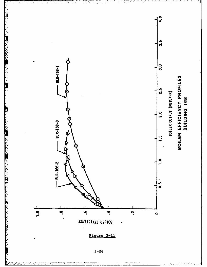
I
.4
CC
T ,-,
-,- J I n
:i "i
fLi
* i 0Nm
w"w
00
3-26
%S

By definition, efficiency is the ratio of energy output to energy input;
therefore, the higher the efficiency, the more heat is delivered per single
gallon of fuel. With the aid of the graph, the operator can choose which
boiler will consume the least fuel at a given heating demand. An operating
schedule can be developed for easy reference. For the example under
consideration the schedule in Figure 3-12 would be appropriate.
Heating Demand Most Efficient
(MBTU/HR) Boiler(s)
.0 - 1.07 BLR-168-2
1.07 - 1.65 BLR-168-3
1.65 - 3.10 BLR-168-1
3.10 - 4.00 BLR-168-1 and BLR-168-2
BOILER SCHEDULE
Figure 3-12
The EMCS operator may also want to generate a log trend of heating demand
versus outside air temperature. If a good correlation exists, then the
boiler operating schedule can be based on outside temperature rather than
heating demand. Of course, a schedule based on ambient te2mperature will be
different for daytime/nighttime and occupied/unoccupied periods due to
solar and internal heat gains.
3-27
,..'

I
APPENDIX A. GLOSSARY
* Apalog:
Representative of a physical parameter by a proportional signal. In an
EMCS it is in the form of a electric signal; the magnitude of the current
is representative of the value.of the parameter.
Architecture:
" The general organization structure of hardware and software.
BASIC:
An acronym for Beginners All-Purpose Symbolic Instruction Code, a
high-level, English-like programming language used for general
applications.
Bootstrap:
A technique or device designed to bring a computer into a desired state by
means of its own action.
British Thermal Unit (BTU)
The quantity of heat required to raise the temperature of one (1) pound of
water by 1°F. An English unit of measure of heat or energy.
Building envelope:
All external surfaces which are subject to climatic impact, for example,
walls, windows, roof, floor, etc.
A-i

Bus:
A circuit within a computer over which data or instructions areS transmitted.
Central Commnunication Controller (CCC):
N A computer that performs data gathering and dissemination from and to theFIDs, as well as providing limited back-up to the CCU.
Central Processing Unit (CPU):
* The portion of a computer that performs the interpretation and execution of
* instructions. It does not include memory or 1/0.
Central Control Unit (CCU):
A process control digital computer that includes a CPU, central memory, and
1/0 bus.
Coefficient of performance:
Ratio of the quantity of refrigeration produced to energy required tooperate equipment.
Conmmunication Link Termination (CIT):
The coummunications interface between field equipment and NCR equipment.
* Control Point AdJusmnt (CPA):
The procedure of changing the operating point of a local loop controller* from a remote location.
A-2
E
.......................

, -. - . - - , . . . -. - . . ." , ". . . . . - ....- .- _ -- . . . . . - - - - -.-. . .. . .
Control Sequence:L.!
Eguipment operating order established upon a correlated set of data
environment conditions.
Damper:
A device used to vary the volume of air passing through an air outlet,inlet or duct.
Data Base:
An organized and structured collection of data stored in computer memoryfrom which specialized data may be extracted, organized, and manipulated by
a program.
Data Environment (DE):
The sensors and control devices connected to a single FID/MUX/IMUX from the
equipment and systems sampled or controlled.
Data Transmission Media (DTM):
Transmission equipment including cables and interface modules (excluding
MODEMs) permitting transmission of digital and analog information.
Deck:
In HVAC terminology, the air discharge of the hot or cold coil in a ductserving a conditioned space.
A-3

Ul ,m n .... , .P .;. . . .. . . . . . . .. .. . . L j. .- ... . .- . - " i ' ,
-
!
Demand:
The term used to describe the maximum rate of use of electrical energy
averaged over a specific interval of time and usually expressed in
kilowatts.
Demultiplexer:
A device used to separate two or more signals previously combined by
compatible multiplexer for transmission over a single circuit.
* Digital:
Representative of an either-or physical state, that is, on or off, open or
closed, etc. In an EMCS discrete physical states are represented by a
current or no current.
Direct Digital Control (DDC):
Sensing and control of processes directly with digital control electronics.
* Enthalpy:
For the purpose of air conditioning, enthalpy is the total heat content of
air usually in units of BTU/LB. It is the sum of sensible and latent heat.
Facility Engineer:
Person in charge of maintaining and operating the physical plant. In the
Army, it is the Facility Engineer (FE), in the Navy, it is the Public Works
Officer, and in the Air Force, it is the Base Civil Engineer.
A-4

Failover Control Board:
A bus switch to transfer the communications function from CCU to CCC in the
.: event of CCU failure, or the communications function from CCC to CCU in the
event of CCC failure.
Fall-Back Mode:
The preselected operating mode of a FID when communications cease with the
MCR or the operating sequence of each local control loop when the FID to
- which it is connected ceases to function.
FORTRAN:
An acronym for FORmula TRANslation. A high-level, English-like programming
I. language used for technical applications.
. Hardware:
. Equipment such as a CPU, memory, pe.ripherals, sensors, and relays.
Abbreviation for input/output, which refers to the data and means by which
it is entered into and retrieved from computer memory.
Interactive:
Functions performed by an operator with the machine prompting or otherwise
assisting these endeavors, while continuing to perform all other tasks as
scheduled.
A-5.

F7 .7
Local Loop Control:
The controls for any system or subsystem which existed prior to theinstallation of an EMCS and which will continue to function when the EMCS
is non-operative.
Master Control Room (MCR):
An area containing the CCU, CCC, operator's console, system terminal,storage devices, printers and other EMCS accessory devices.
Microcomputer:
A computer system based on a microprocessor and containing all the memoryand interface hardware necessary to perform calculations and specified
transformations.
Microprocessor:
A central processing unit fabricated as one integrated circuit.
MODEM:
An acronym for MOdulator/DEModulater. A hardware device used for changingdigital information to and from an analog form to allow transmission over
*' voice grade circuits.
PASCAL:
A *structured programing" high-level computer language.
A-6

Peripheral.:
A-device used for storing data, entering it into or retrieving it from a
. computer. Examples of such devices are a flexible disk system and a line
printer.
Pneumatic:
Of, operated by, or filled with air or another gas. A pneumatic control
system is energized with compressed air which is piped throughout a
- building.
Point:
Individually connected monitor or control devices (i.e., relay, temperature
sensor).
Predictor/Corrector:
Applications software which mathematically predicts future values based on
past and present values, and subsequent correction.
Program:
A sequence of instructions causing the computer to perform a specified
* - function.
Real Time:
A situation in which a computer monitors, evaluates, reaches decisions, and
effects controls within the response time of the fastest phenomenon.
A-7

Resistance Temperature
Detector (RTD):
A device where resistance changes linearly as a function of temperature.
Software:
A term used to describe all programs whether in machine, assembly, or
*high-level language.
Ton:
A measure of cooling capacity equivalent to 12,000 Btu/hr, the rate of heat
absorption as one ton of ice melts over a 24 hour period.
Zone:
An area composed of a building, a portion of a building, or a group ofbuildings affected by a single device or piece of equipment.
A-8

APPENDIX B.
SAMPLE LOG TRENDS AND REPORTS
B-1
-oI

ELECTRICAL POWER UTILIZATION SUMMARY
REQUESTED BY: JBR S/ 9/1983 23:19:10
METER NO. 1 ADMINISTRATION BLDG
DAY KWH PEAK KW TIME
5/ 1/83 85,300 4221 7:135/ 2/83 257,400 10944 15:555/ 3/83 263,900 11056 15:325/ 4/83 261,600 10931 15:415/ 5/83 265,400 10872 15:465/ 6/83 252,200 11211 15:275/ 7/83 173,400 7814 12:515/ 8/83 88,700 4003 7:42
LAST MO. 6,752,400THIS MO. 1,647,900
CONSUMPTION RECORD TODAY:
INTERVAL KWH PEAK KW:03:33 5363 10753
1:03 5186 103881:33 4991 103762:03 4801 9583
B-2. .

. . . . . . .... . . . . . . . .5.
ENERGY UTILIZATION SUMMARY
*REQUESTED BY: JXD 12/20/83 14:12:08OAT =43.1*F
HOUSING RH =33%
MAX MBTUMBTU/HR ELEC GAS OIL TOTAL
12/19/83 239 1501 * 85 1288 287412/20/83 215 834 62 702 1598November 244 53848 1702 16618 72168
- December 239 30571 1626 24743 56940
B- 3
S~~~1 - --

13:01 '09/15/82 WED MASTER CONSOLE MCC 150.8 DEG F 24.0 KWH
ALARM SUMMARY PAGE 001
POINT CURRENT ENG. ALARM
USER/ENGLISH NAME DESCRIPTION STATUS/VALUE UNITS STATUS
CLASS 1 MAIN BLDG W. SMOKE ZONE SMOKE **ALM**
CLASS 2 CHPUMP CHW PUMP ON **ALM**MAIN BLDG COOLING 01 CHILLER 1 ON **ALM**MAIN BLDG COOLING 03 CHW PUMP ON **ALM**MAIN BLDG COOLING 07 CLG TOWER LO ON **ALM**MAIN BLDG COOLING 08 CLG TOWER HI ON **ALM**MAIN BLDG COOLING 09 COND PUMP ON **ALM**
CLASS 3 MAIN BLDG ZONE 1 SPACE TEMP 86.1 DEG F **ALM**MAIN BLDG ZONE 3 SPACE TEMP 79.2 DEG F **ALM**MAIN BLDG ZONE 4 SPACE TEMP 83.5 DEG F **ALM**
--
-a.
* 8-4

.-
LOCKOUT SUMMARY REQUESTED BY: 0 0 4/22/1980 17: 5:58
T TEST PANEL S SUPPLY FAN 11 SUPPLY FAN 1 LOCKED OUT14 WALL TEMP LOCKED OUT
15ROOM TEMP LOCKED OUT16HIGH ZONE LOCKED OUT17LOW ZONE LOCKED OUT
B-5
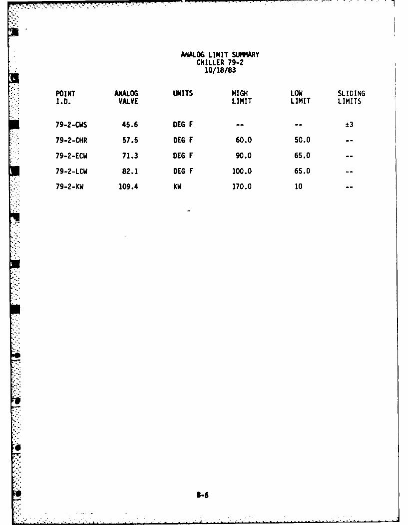
AKALOG LIMIT SUMMARYCHILLER 79-2
10/18/83
POINT ANALOG UNITS HIGH LOW SLIDINGI.D. VALVE LIMIT LIMIT LIMITS
79-2-CWS 45.6 DEG F - ±3
79-2-CHR 57.5 DEG F 60.0 50.0 -
79-2-ECW 71.3 DEG F 90.0 65.0 -
79-2-LCW 82.1 DEG F 100.0 65.0 -
79-2-KW 109.4 KW 170.0 10 -
* 3-6

C,-31 rP %C %00 04 -
rit 4 o r V4'W -4 q 4'l4p fl) '4
z- z
ni *-4 ei r*.4F 4qr . t1. i i- it
u 00
--- rl '- r4 --iir r- r4 - , ,r . 3c ,c j L
2:2 X.0
-~I.-
0 <C. 'C
W4'-
0 0
* -1 .- - 0- Li
-a ~ ~ ~ ~ ~ ~~~~~~~~~~L orrC %,)i0q r 2Cw r 2C j004Z- '4i civ~4 '4 pi pia 'V C'd'?qrI,) ial'4,3 4 INI%,%r oc C- ' C.)
- C.. U

-- -
"" COOLING TOWER PROFILE5/28/83
+.i
DAILY DAILY TOTAL MONTH TO DATECOOLING TOWERS: TOTAL ON TIME ON-OFF TRANSITIONS TOTAL ON LINETOWER #1-FAN #1 9 1 45
#2 8 3 32#3 5 18 25#4 0 0 10
TOWER #2-FAN #1 0 0 20#2 0 0 15#3 0 0 0#4 0 0 0
TOWER #3-FAN #1 9 1 18#2 7 5 14#3 4 16 8#4 0 0 0
CONDENSER WATER COMMON:DAILY: MAX TEMP 89.2 DEG F/1320 MIN TEMP 71.4 DEG F/0630
MONTH TO DATE: MAX TEMP 92.1 DEG F/05/22/1330 MIN TEMP 66.5 DEG F/05/02/0640
P--B

TASK?RE 1/15/80
POWER DEMAND REPORT FOR METER 1
PROG MEASURED PREDICTED REDUCTION LIMIT TIME AND DATE0 1300 KW 1452 KW 249 KWH 1999 KW 00:21 01/15/80
" 0 1350 KW 1486 KW 250 KWH 1999 KW 00:51 01/15/800 1311 KW 1438 KW 249 KWH 1999 KW 01:21 01/15/800 1323 KW 1435 KW 249 KWH 1999 KW 01:51 01/15/800 1323 KW 1471 KW 250 KWH 1999 KW 02:21 01/15/800 1320 KW 1464 KW 249 KWH 1999 KW 02:51 01/15/800 1338 KW 1471 KW 249 KWH 1999 KW 03:21 01/15/800 1323 KW 1446 KW 250 KWH 1999 KW 03:51 01/15/80
- MAX= 1381 KW , SHED= 17,006 KWH I TOTAL=115,574 KWHO 1323 KW 1450 KW 249 KWH 1999 KW 04:21 01/15/800 1299 KW 1435 KW 249 KWH 1999 KW 04:51 01/15/800 1342 KW 1491 KW 250 KWH 1999 KW 05:21 01/15/800 1335 KW 1479 KW 249 KWH 1999 KW 05:51 01/15/80
MAX= 1381 KW ,SHED= 18,006 KWH , TOTAL=118,224 KWH0 1350 KW 1480 KW 249 KWH 1999 KW 06:21 01/15/800 1324 KW 1441 KW 250 KWH 1999 KW 06:51 01/15/801 1311 KW 1465 KW 42 KWH 1999 KW 07:21 01/15/801 1342 KW 1476 KW 54 KWH 1999 KW 07:51 01/15/801 1329 KW 1443 KW 68 KWH 1399 KW 08:21 01/15/80
MAX= 1381 KW , SHED= 18,672 KWH , TOTAL=121,552 KWH
B-9

Cj &n n Mn
i n
000000 0 0D 0 D CD a
Q 000000Q 0 C) Q 0D CD 0D
C21
G$aCD8 000000 10 0D 0D 0o C0 0
C)a t0-4 9.
~OO 00 000 0 0 0 0
ac
q r- ) 40i n e
*n SO P%.' 0 P.
Co 0% %=c V0 a-6
§W InNNN e4 0% 0
CD~a an9-n &n
W). cc) I. u muS ONOOO 0 1-- 0CI-
NOO &' .0k& k U
Xa :C 12 tc a .Lan
B-1

rm-
OPTIMUM START TIME SUMMARY 11/ 2/1901 15:22:56
SF1 SUPPLY FAN 1 CURRENT STATUS CLOSED
CURRENT OPERATIONAL VALUESMODE HEATINGOCCUPANCY SCHEDULE (TIME AND DOW): 7: 0 1 ------ 78OUTSIDE AIR TEMP SENSOR TC ,ATMPATB 65.0 DEG.INSIDE AIR TEMP SENSOR TC ,ATMP,ATA 64.0 DEG.ZONE AIR TEMP SENSOR TC ,ATMP,ATC 64.0 DEG.NO ADJUSTMENT TEMP 75.0 DEGFMAX OUTSIDE AIR TEMP 100.0 DEGFOCCUPANCY TEMP REACHED WITHIN 20 MINS NO
-1
"I
iB-l

OUT-OF-SERVICE REPORT 8/14/84 3:14:10
FID # 4 CLOSED
MUX # 3 CLOSED MLIX # 6 CLOSED MUX # 7 CLOSED
14UX # 8 CLOSED
********THE END *****
B-12z

71" .x-7--'7- 7-- -.-
ALL POINT LOG REPORT
POINT CURRENT ENG ALARM
USER/ENGLISH NAME DESCRIPTION STATUS/VALUE UNITS STATUS
ADM BLDG AHU SF SUPPLY FAN ON NRML
ADM BLDG AHU RF RETURN FAN ON NRFL
ADM BLDG AHU MA MIXED AIR 55.1 DEG F NRML
ADM BLDG AHU SA SUPPLY AIR 63.5 DEG F **ALM**
B-13

.. U.
a z w z r u
L o, c 0 qr0 0
(%I - -
i c InW MnI L DN U L)I.- z0 w lw
z Im
LL U~W w c 6CicrW IM LAW W_
2: ~ ** -1 -.U
f wf ~ ai LI (~~~ r M.4

az .rv. 'r *. z
ON MSN M N N~ M" 00*n00 - -V - 0 O M
OOO~C~O 0C~ WOCOOO4-ULca
W~44~4O~)w4~iN~4' N 4 000000o
0oo0o-0000o000o000 0 -4--,000000
i.
z z zZ Z Z zZZ z0 = CD 0 0 mom0
LL L L L- LLW & WLLLL LLLLA. LL LL LL L. LLLL LL
* W ~ ~ 000C000044~
"I - * *
~~~ x NNNN~NNNNN w '0 'Cf0.
0 O000000000-00O0-00 00.-000000
CLol
* - -Z =,'= =Z=no D = ML0 L-D = L
-~ Z ~ : 1-.D)f Z Z Z Z
N i,-' - 1.
%CN N'~ N N ~ N 0O~~ IT - 0-'rm i1 l 1 or
0 7j 'n4 -
Z~ZZMZ m z zzzzzzc
r-=ZZZZ c 0-ozoo
.~~~i '0 rl0JC N .4 N V N~ 0 NJ~4 ' 0 0 '0 a0 0 vo 0 0 0. 0w InJ0 N w~ M ' V~ 'o D. N V Li 0i Z In . 0 M M 0 m' 0 0 0k 0
~ 0 0-4Cjk
0 00 00 00k0000000000 0 0k- N0 0*- MN O N MVI q.0N0
B-15

LL..
ini
u 1 X k0 nt i
w 1. LX ra0 3 2 L :
U) 0Iz II
CD It I Il w I
0 lk IX I U) Z "IA3- ia IL W II J WI ZI
06 ii C& O 0- I III CI U !pz iC0 L (
a I. oI
ii II

BOILER PROFILEBLR-168-1
11/15/83 10:03:57
BOILER STATUS: ON
Ij BOILER OUTPUT STEAM PRESSURE: 12.3 psig
STEAM TEMPERATURE: 265.1 OF
STEAM OUTPUT: 1395 LB/HR
BOILER OUTPUT: - 1.34 MBTU/HR
FUEL INPUT: 14.2 GAL/HR
ENERGY INPUT: 1.97 MBTU/HR
INSTANTANEOUS EFFICIENCY: 68%
FEEDWATER TEMPERATURE: 187.60F
OUTSIDE TEMPERATURE: 41.70F
SEASONAL EFFICIENCY: 69%
B-i7

CHILLER 23-1 PROFILE
9/22/83
" CHILLED WATER: SUPPLY TEMP 68.7 DEG F RETURN TEMP 72.2 DEG F FLOW 200 GPMCONDENSER WATER: SUPPLY TEMP 85.4 DEG F RETURN TEMP 85.4 DEG F FLOW 270 GPMENERGY FLOW: CHILLER AND AUXILIARIES 0 KWTOTALIZED ENERGY TO DATE:
DAY a 102 KWHWEEK a 414 KWH
* COST PER UNIT ENERGY: EL = $.04/KWHTOTAL COST OF ENERGY TO DATE:
TODAY - $4.08 WEEK - $16.56LOAD RATE: INSTANTANEOUS - 0.0 MBTU/HR AVG. TODAY = .45 MBTU/HRTOTALIZED BTU LOAD: TODAY .985 MBTU WEEK: 4.10 MBTUCOEFFICIENT OF PERFORMANCE:
INSTANTANEOUS = 0.0 DAY = 2.83WEEK "2.90 SEASON = 3.2
COST OF BTU: TODAY - $4.14/MBTU WEEK: $4.04/MBTU
NOTE: MBTU MILLION BTU
B-18

DAILY AHU FAN ENERGY CONSUMPTIONBUILDING 23
5/28/83
AHU FAN SIZE RUN-TIME ENERGY
NO. HP MIN. KWH
1 3 465 13.9
2 2 392 7.8
3 71 404 30.1
4 1 433 4.3
5A 5 387 19.2
58 5 387 19.2
6 3 425 12.7
TOTAL ENERGY CONSUMPTION TODAY = 107.2 KWH
B-19

w
0: It I 0: 1-I : 0 0 :& :itmI
LLI,
t I CDaC PaND pI
z 4' 6o 40 in (I% ir- Nvwlp . Q
zt 91 0 z2 0z~ %a0M 5 ,I. NO 00v ZZN NX N 4cN %0 ~ 0 00 0 00 D NCD40 it0
a I. w I0. I N1
z I. I- zZI. mmmm mm ccD 04r C2 ~ 0") 't:OCw ww w 0.00 ww q 000 -1 qN sON *O ON WUO- N:I
z ~ 4N N mN I.- I.-N. I.- N 0 n .W-U 0 10:ww wlsmI) f j py 0- Uz w !.
zmIm x : - j (kjI I-1Iu-U U . f M
Iiw2X 2702 :3XCW- ILt LL -LLZ W X X 210 )
w z a wi ~ i ~ .JJ lW )Z ~ 0. I-~
2 ~ ~ ~ I 22 0:!~ CrZ0 CfU.DUI 0.-2 NZ . 0
"h~C i0~ OO O W IU L0 n
z~E 00 .a: Li -1 a z i II. aZN
*2 01 44 _ a i- j1W i IL 0:1. Ezoo a a , a
N' An m a: ZzC x O
LL Z P- 0 A-Ja: c 0 z0(z00 a 0 0
wI r :30 - a 0.i- j J i L
maca 2323232222a CeE-44 a a m aaau w LU. L:0w w 3c wj g j JjJE EE~ r xr x 0mw.
ee 0-N C Iws:6-I Iw
1'g 121Br33S

BUILDING 402 ENERGY AUDIT FOR WEEK ENDING MARCH 6, 1984
1 KWH OF ELECTRICITY
WEEKDATE 2/29 3/1 3/2 3/3 3/4 3/5 3/6 TOTAL
* BUDGET/DAY 333 333 333 333 333 333 20 2000
CORRECTED BUDGET/DAY 300 300 300 250 250 300 30 1730
" ACTUAL/DAY USED 315 330 350 360 280 350 20 1945
BUDGET DEVIATION 18 3 -17 33 53 -17 0 73(BUDGET MINUS ACTUAL)
PERFORMANCE RATIO 1.05 1.10 1.45 1.20 1.12 1.33 0.68 1.19IACTUAL/CORRECTED
BUDGET)
DAILY TEMP RANGE 40/16 43/18 53/25 60/32 51/18 38/10 32/8
-, HI/LO
ACTUAL DEGREE DAYS 6 8 10 8 6 5 3 46
BUDGET DEGREE DAYS 8 9 10 10 10 9 8 60
B-21

o 0 0o 0 0
u Cd 0000
u 0 0 0 b)WILIh 0
CC Nd NZ.J C. C! 0 0
V l. 0IN 0
0
i - 0 f.4 "0 C
I.- N Of. el .4
00 0 000 0
* 1P 0.4x
00- . 0 00 04 N 0A0 c u- 4:-0 00 b 0 00 03 c- 0 0. 4 h
0-I hI . c 4 bl l 0i. C.
4t a~ Cd m.) p -4= I.- 1 0 Cd .4C
0AM ' 0 .4 .4 hI 0 0 =- .Li -i 00N0 c .
Z4c c .4 P1C i A u*J 0 0
LI~ ~~~ 0. 00 0 0 0 0L -
LI 00~ 0 :~ 00 00 0)1- 00 0 -3. 00 02 caPsI
Cc .41 I' 0P .4 CA C N dO
Li 49 0i0Z~ ~ ~ ~ 0 3C.
Um 00 0000b 00 0 04 co 00 00 C 00 0
LJ NO Pd 4;0 Cd PO 0
NO q 0 0
0- 00 C- P.. .2 000 0 P0. 02 C
§L . .
P4 hI.u.44 ' 4 0
- C20 00 0 ~ .U P-2 0 Ie 1- $-. 0
LI c71 C' PI, N 2 C
00 to P.1 - w- I W
B-22

SUPPLEMENTARY ALARM SUMMARY REQUESTED BY: 0 0 4/24/1980 19:27:20
1 CHECK BOILER FUNCTION2 CHECK COOLING COIL FUNCTION3 SUPPLY FAN NOT OPERABLE, CHECK H-O-A SWITCH4 CHECK AHU-1 COLD DUCT TEMP AND CHILLER FLOW5 CHECK CONDENSER PUMP6 CHECK COOLING TOWER FAN7 CHECK CHILLER STATUS
- 8 CHECK CHILLER WATER SUPPLY PUMP- 9 CHECK ENTHALPY SWITCHOVER
.0
".°
8-23

CORRELATED ALARM REPORTBLDG-12-CV-1-HWS TEMP IN ALARM
3/15/83 9:07:18
LOW AT 105.9*F SETPOINT - 114.7LIMITS: LO 111.70 HI - 117.70
POINT CURRENT ENG ALARM
USER/ENGLISH NAME DESCRIPTION STATUS/VALUE UNITS STATUS
BLDG 12 CONV1 PUMP PUMP ON NRML
BLDG 12 CONV1 VALVE VALVE POS. 55 % OPEN NRML
BLDG 12 BLR STEAM PRESSURE 5.3 PSIG NRML
BLDG 12 BLR STEAM TEMP. 227 OF NRML
BLDG 12 BLR STATUS ON NRML
B-24
- -
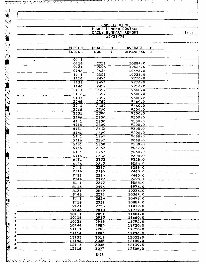
CAMP LEJEU.NFFWER DEMANI CDNTR)L
. DAILY SUMMARY REPORT
112/31/78
PERIOD USAGE H AVERAGF HENDING KWH I DEMANI)-KW I
0* 1.016 2721 10884.0
031 2656 10624.-00:46 2624 10496.010 1 25.39 10236.01:16 2494 9976.01:31 2494 9976.()1:46 2429 9716.02: 1 2397 958.8.(2:16 2397 9588.02:31 2397 9588.0
( 2:46 2365 9460.03: 1 2365 9460.03:16 2300 9200.03:31 2300 9200.03:46 2300 9200.04: 1 2300 9200.04:16 2300 9200.04:31 2332 9328.04:46 2300 9200.05: 1 2267 9068.05:16 2267 9068.05:31 2300 9200.05:46 2267 9037.9
60 1 2279068.06:*16 2332 9328.06:31 2332 9328.06:46 2397 9588.07: 1 2397 9588.07:16 2365 9460.07:31 2365 9460.0
7:46 2397 9620.18: 1 2397 9588.0
68:16 2494 9976.08:31 2559 10236.08:46 2591 10364.09: 1 2624 10496.09:16 2721 10884,09:31 2753 11012.09:46 2818 11272.0
12 . 10: 1 2851 11404.010:16 2915 11660.0
10 10:31 2948 11792.09 10:46 2980 11920.0" 11 1 2980 11920.0
1111 29A 11970.0- 11:31 3013 12052.0. 11146 3045 12180,0
412: 1 3045 12139.512116 3077 12308.0
B-25

-, _______"____DAILY SUMMARY REPORT12/31/78
PERIOD USAGE H AVERAGE HENDING KWH I DEMANi-KW 1
12:1612:31 3077 12308.012:46 3045 12180.013: 1 3110 12440.013:16 3077 123090o
"-_13:31 3077 12308.01 ".46 3077 1 309o
14: 1 3013 12092.314:16 3013 120t 2.014:31 2980 11920.0
14:46 2980 11920.015: 1 2980 11920.015:16 2980 11920.015:31 3013 12052.015:46 3045 12180.0
___16: 1 3110 12440.0"16:16 3045 12180.0
__________ ___16:*31 3077 12308.016:46 3110 1-0-017: 1 3110 12440.017:16 3207 12826.017#*31 3337 13348.017:46 3434 13736.01s: 1 3434 13736.018:16 3466 13864.018:31 3466 * 13864.0
18:46 3466 * 13864.019: 1 3434 13736.0
19:16 3401 13604.0__19:31 3337 13348.0,.. - fV:46 3304 f32i6. 0
20: 1 3239 12956.020:16 3239 12956.020:31 3175 12700.020:46 3175 12700.021: 1 3077 1230B.021:16 3077 - 12308.021:31 3077 12308.021:46 2980 11920.022: 1 2915 11660.0
22:16 2883 11532.022:31 2851 11404.02246 2786 11144.0
23: 1 2721 10884.0
N 23:16 2689 10756.023:31 2624 10496.0
23:46 2624 10496.00 0: 1 2591 10364.0
, TOTAL 269702.
B NO LOADS SHED

I
CAMP LEJLUtJED'AILY OUlSIDE TLMprLRATUIpE REPORT
PER IOD TEMrERATU:NE"
24:00 TO 100 42. 4
1:00 To 2:00 40.10'2:00 TO 3000 37.073:00 TO 4100 37.174:00 TO "10W30 34.40;w:o5o0 TO 6:00 34.11
6:00 TO 7100 33. 46700 TO r 00 34.000:00 TO 9:00 37."9:00 TO 10:00 40.14
10:00 TO 14:00 41.14
11:00 TO 12 00 44.761200 TO 13 00 41513 00 TO 14 00 40.2114*00 TO 15:00 *15000 TO 1L:00 *1*00 TO 1710017:00 I' 1if0 010:00 TO 19:0019000 TO 000t20:00 TO 21:00 l21:00 TO 22:00 *
22:00 TO 23:00 0 *
23 *00 TO 24:00
AVERAGE 39 057
B-27

,+ • . • , .. - .• + , . .+ .. .
AHU 23-1SELECTED POINT DAILY TREND LOG
9/22/83
TIME FAN SPACESTATUS TEMPERATURE
1:00 ON 76.42:00 ON 70.83:00 ON 69.54:00 ON 68.35:00 ON 67.56:00 ON 66.67:00 ON 65.88:00 ON 65.69:00 OFF 66.3
10:00 OFF 67.911:00 OFF 68.812:00 OFF 70.113:00 - OFF 72.414:00 OFF 75.615:00 ON 78.316:00 ON 77.517:00 OFF 77.618:00 OFF 78.219:00 OFF 78.520:00 OFF 77.921:00 OFF 77.822:00 OFF 77.523:00 OFF 77.124:00 OFF 76.6
FAN RUN-TIME - 578 MIN
B-28
U . . . . . - - - - . - - . . - - -

.4l
I 'I 1
.1
w 01 0
o z1
EU 0
I pI CL Inz I'4 C Yj
0 i Ml,04 Z
-W 0 0 0! C-OW I ~ZZM1 a M;
0~2 z Iu ai x 0n 2 I Z CCi S-1 4
InU CL CL 0.. :0.CI- _IO 10U0 0:
.4 a!, I
a u IAS_j 0: U:2! w w CL : -*j :X 01 K, a:4C lW m9ZI z 9 cnI-~ 0m Olt :w z tzCD 0.0 WU- U~W c- ' - it (A
ID M-. w Z C U h w m0 hCi -I h
20 aW Izw Q IJw cc w co Cam i ,ZSI- 4 j C CL D . I-~ - i I A- 0 zo! a: .4
.0 j4CC C W C. WCO .a4. a:-40 w hM:~ Z* IL. W i0 hZ 0 WX IC AL :D. 0aE~ .. E -i X -X
a 0i ,x U u a: U..
00 Z 6-29
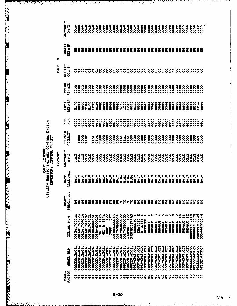
3 -00 3 .3 -3
anI 00000000800000000000000000000000000000
4
44 0000000000000000000000000000000000000i-ZZ=ZZZ-zzz Zz~zz zz z zzz~zz zZ=Z = z z :
0
u a
R a=.00 .44C NOOOOO 4.4.40.0000 0000 00000 00 c.4 C)t- C= 0000000000000000000000000000000000000
Li 0
4c~ 0 0 0, 0 0 0 . 0 C) 0 0 0 0 0 0 0 0 0 0 0 0 0 0 0 0 0 0 C) 0 0 C) 0 0 0 0 0 0Z000000040000000000000000000000000 00000
.0000C00000000000O.000000000000000000
P- 00 ~OOc.'1000000t,4CflP10CdO0000000000000000-3 0
_.j U OOOC0.40000000. d4.40000000000000000000
or O00 "0.4 400000400000 00 000 000000 0 DOC0=~ 00000-4000000-4-44000000000000000000000
Li a= 000000000 000000000000000000000000000000 00 000 0000000000 000 00 000000000 0000 0
0-f- elu OOc. .4-000400000 0000OOOO0000000000000.40
0 a
= 3-
.. QLO Cd =10 0000000000000000000000000000000000000WU ! 4
ILLa
0 La W4. . ....... 4. . 0 0 0 0 ".4 .4.4.4.-.4.4 .4.4 -4..4.4 .4.4 q.4l: 4CLa 00000000000000.4.4.0400000000C3000000 00000
Qu00 00000000000000000000000)000000000003- 04
.4Q
-Ca
0 0 0 0 0 0- " 00 OO 00UULJUON 0 0 000000 000 0
r.r N Nl II ... .4 .4 3 %)C CI 0 0 0 U1 JdC 444C I~S C 0 0 :) Z: :3 Z.00 0 0. .4.NO 04 0.4P weI) wV fVbbb) !1 c'q a Q m r 00 00
u " W4.00" " "000 .Ge.--L a-4a a laU2 aa000000000000 0000 000
.00000 .0000 0 0Z. 3La0O 0000000000oc
od '44.444 K i o.4 .4 .44 "9 Ar AN A 4C 4C 0 00 0L 0000000 00000000000OCOOOLh
a 9 " 999 94 94. " " 9 " 994 g 9 4 " 9 Ci N 0 0 01P 0 ff P0 ff 1 P1 1 CI C- C- a a
M oOOOOOOOOoOOOOO dd 0 N C C4 Cd CA Cd Cd CA Cd t C CN C C" 4 WONCd Ud C C C C C C CA rd CA N A N C C N w 40 qr 4w 4v qr qrtv q qr 4v 4f- ml 61 SIL CA Cd CIA Cd4 C C C CIA d CdN N Nd CA CA .C .C LC C. hC. L h C. LL 5 S S
000000 00 000 0 0000 LI LischtstshLIL L L I IIL LI 004.4w4.0090900000000800800000000
@00000000003 000 00000000000000000
0000000000000000000000000000000000000
B-30

. . . . . . . ......................
Li..*
- z . . . . .
0~~~ . *.
'- z
I. 44 2r ... 4.....444444..4 ol N4. -4. 0 4.4 0 IN' n4 0 1 0.4u rqr I-1 00N 0C i. r 40 oNw 0 C , NNK6
Li 0
0~ b) 0 L
-1 612 NZ aL
C, C-1 0 000 0
CJ Z ~ LJ D. Zz== 3Iv z r
L)t0 .44 j0. ZZZZOL33 (- u.L, 0 ~ A: eaN0
C0 z zzzwi0 Coco-~ 00
L*j 00000-0rarrwrvwr ree000000W0000000N0r0000
Li 0000000000044..40000000000 00000000o
.4?")J',r*tWJO~O00000oOOO0000000000000000o
ULi
Z iJ
8-31

Li . . .
* a a
* a a
or *.
41 zaC...
0 4z L* -j iLi 4t a .
Li = .'
C..C7
M 0 . a~ 0-
47 w a3 Na.
z 0 4
LI " .0 e C
s~us
LIwC II L
7--or
~.--E0-32

0rr 0 -, P -0N i0
*L. t~ . . . . . . . . . . . .
Li #7 hiiiiiiabhQ
P4 0 Wii4N4C C.000 0L~~Z .4..4 O0 0 4.4 4
N :t zr r zt zzfM 0 Nvo.2V
Liz 44 .....
ulrito-0q C P. .4.4~
U~~~ ..2iO. . . . . . . . . .
49. q hi -4 1w '.4'0 0 ,C 04-1-0-
Li C- . .............> rrrrN~rN-% r
cz
Li2 00000000000000
. Li
-~q-4
Vr 0 ur~rrr.-t L r
o Li Cri ~ ~ ~ ~ L 2hit C )I
hi 4 qhiq 3 .0N.CC ('. 0O0 0 = .. ..s.4 . . . .00. . . . .
il iru lil10u nilulb 1 )u
b) to ul bi r ll It M) in t hrb
U) C30. 0h.rJP P.)-04,4pWM.~ . . . ...
Li 0 4 4
C%- M- hi C 04Ii4 C% hi# .4 3
.2j
0- 33

00 Z Z Z
azivz zkz Za z heU) i U) 0 00 o 0 ~ p
IN NINN NN I
W~~~~qq MWWWWMMWIMW W W W wwwm
C N N~ N M M" 4o 4 "
0n~ N% inq - -w w 0 0 V3 m 0 MNwMn nL
C) 0 MS f4 Jj. N r*_ 4..b.. CV, 0 0 Ne
r- s o a oa o o 0 6a sa os.s *b -. .
4I 4W L 0 a 0 0 I 1 -.N CYNNI g nI n%
Is-3*~0 V'O 0000 tk *D 0 - -- 0---

DISTRIBUTION LIST
AF HO LEEEU (Aimone). Wash.. DCAFB AFCS/DEO (Corbett), Scott AFB. IL: AFSC/DEE. Andrews AFB. Wash. DC; HO AFLCJDEE (EMCS
Mgr), Wright-Patterson AFB. OH: HQ0 ATC/DEM (Ling). Randolph AFB. TX. HO PACAF/DEE (EMCSMgr). Hickan AFB, I: HQ SAC/DEE (Butters). Offutt AFB. NE: HO SAC/DEER. Offutt AFB. NE; HOSAC/DEM (TIonsi). Offutt AFB, NE: 110 SPACECOM/DE (Moytinia). Peterson AFB. CO; HO0 TAC/DEE(Scercy). Langley AFB. VA: HO TAC!DEM (White). Langley AFB. VA; MAC'DEE (West). Scott AFB. ILMAC/DEN! (Koschl. Scott AFB. IL
AFESC DEB (Stother). Tyndall AFB. FLUSAF-AAC DEE. Elrncndorf AFB, AKARMY CORPS OF ENGINEERS DAEN-MPC-C (Wharry). Wash.. DC: DAEN-MPE-E (Brake), Wash., DC;
DAEN-MPE-E (Mc('arthy). Wash.. D)C, 1AEN-MPO-U (Walton). Wash.. DCARMY ENG DIV EUDED-TM (O'Malley).: IINDED-ME (Carlen). Huntsville. AL; HNDED-ME (DeShazo),
Huntsv-ille. AL: HNDED-ME (Herden). Hunsiville. AL: HNDED-ME (Holland). Huntsville. AL:HNDED-ME (Wilcox), Huntsville. AL: HNDED-PM (Brown). Huntsville. AL; HNDED-PM (Ganus).Huntsville. AL: MRDED-TM (Beranek), Omaha. NE: MRDED-TM (Jones). Omaha. NE: NADCO-CM(Eng). New York. NY: NADEN-TM (Stuart). New York. NY: NPDEN-TE (Wottlin). Portland. OR:ORDED-T. (Norman). Cincinnati. OH: PODED-T (Nakasone). Ft. Shafter. HI: SADCO-CC (Mindel).Atlanta. GA: SADEN-TE (Smith). Atlanta. GA: SPDEI).TG (Kishaha) San Francisco. CA: SWDED-M
* (Powell). Dallas. TX* ARMY ENGR DIST. CO. Tulsa. OK: MRKED-DM (Rahuse). Kansas City. MO: MRKED-M (McCollum),
Kansas City. MO: MROCD-SM (Hall). Omaha. NE: MROCD-SM (O'Brien). Omaha. NE, MROED-DC(Sawick). Omaha. NE:. NABCO-S (Meisel), Baltimore. MD: NABEN-D (Kelly). Baltimore. MD:NANCO-C (Spector). New York. NY: NANEN-DM (Kessenides). New York. NY NAOEN-MA
* . (Daughety). Norfolk. VA: NAOOP-C (Herndon), Norfolk. VA: NPSEN-DB (Eason), Seattle, WA:ORLED-D (Pfeifer). Louisville. KY: SAMCO-Sl (Rawls) Mobile. AL; SAMEN-C (Anderson). Mobile. AL-.
* SAMEN-CI (Tunnell). Mobile. AL: SASEN-DF (Plunkett). Savannah. GA: SASEN-MA (Grimes).Savannah. GA: SCD-SB (Stone). Savannah. GA: SPKCO-C (Del Porto), Sacramento. CA: SPKCO-C(Evans). Sacramento. CA: SPKED-M (Lowell). Sacramento. CA: SPKED-M (Stoner). Sacramento. CA:,SPLCO-CS (Molina), Los Angeles, CA: SWFCD-ST (Ready). Ft. Worth. TX: SWFCD-ST (Wood). Ft.Worth. TX; SWFED-DM (Story). Ft. Worth. TX; SWFED-DM (Wike). Ft. Worth. TX
* NAVFACENGCOM Code 03 Alexandria. VA: Code 03T (Essoglou) Alexandria. VA; Code 04 Alexandria VA:Code 04T2 (Knapp). Alexandria. VA: Code 04T2B (McGrath), Alexandria. VA; Code 0417B (Stickley),Alexandria. VA: Code 05DI (Bcrsson). Alexandria. VA; Code 09M54. Tech Lib. Alexandria. VA: CodeIIl (Mitchum). Alexandria. VA: Code 1112E (Tayler). Alexandria. VA: Code 1118 (Hanneman).Alexandria. VA
NAVFACENGCOM -CHES DIV. CO. Washington DCNAVFACENGCOM .LANT DIV. Norfolk. VANAVFACENGCOM- NORTH DIV. CONAVFACENGCOM -PAC DIV. Commander. Pearl Harbor. HI
* NAVFACENGCOM -SOUTH DIV. CO. Charleston SCNAVFACENGCOM .WEST DIV. San Bruno. CANAVFACENGCOM CONTRACTS 01CC. Kings Bay. GA
14 NAVSH1PYD PWO. Marc Is.USAF AFRCE/CR (Walton). Dallas. Tx; AFR(E/ER (Burns). Atlanta. GA: AFRCE/M-X (Stevens). Norton
AFB. CA; AFRCE/WR (Lowry). San Francisco. CAUSAFE HO DEE (EMCS Mgr). Ramstein AFB, Germany
I7