energy and exergy analysis for a steam cycle of north
TRANSCRIPT

Journal of Mechanical Engineering Research and Developments
ISSN: 1024-1752
CODEN: JERDFO
Vol. 44, No. 8, pp. 439-456
Published Year 2021
439
Energy and Exergy Analysis for a Steam Cycle of North
Refineries Company (NRC)/Baiji, Iraq
Hameed J. Khalaf †, Waad A. Salih
ffi, *, Aadel A. Alkumait
†
† Mechanical Engineering department, Tikrit University, Iraq.
ffi North Refineries Company (NRC)/ Baiji, Iraq.
* Corresponding author email: [email protected]
ABSTRACT
This study presents an energy and exergy analysis for steam cycle in a petrochemical refinery in North
Refineries Company (NRC)/Baiji, IRAQ. The study starts with setting up a mathematical model based on mass,
energy, and exergy balance equations for each component of the cycle separately, recording the operational data
(pressure, temperature, and mass flowrates) for the cycle at real and rated loading. Calculations were done by
using (MATLAB) platform. The results of energy analysis showed that the total energy losses were 98.89 MW
and 119.85 MW for real and rated loading, respectively. The largest energy dissipation was found in the
condensers which represents 32.01% and 29.79% from the total energy loss at the two rating loads, respectively.
The 1st-law efficiencies for the cycle at real and rated loading were found to be 36.27% and 38.63%,
respectively. The exergy analysis based on the 2nd-law of thermodynamics showed different and interested
results, it explained that the total exergy destruction at real and rated loads are 61.58 MW and 75.13 MW,
respectively, and the largest destruction in exergy occurs in boilers and found to be 45.99% and 45.25% of the
total exergy destruction at real and rated loads, respectively. Turbines, condensers and heat exchangers are
following the boilers in the values of exergy destruction and found to be 15.54%, 13.64% and 5.98%,
respectively, at real load, and 14.53%, 12.7%, and 6.45%, respectively, at rated load. The 2nd-law efficiency for
the two loading rates were 23.65% and 22.6%, respectively.
KEYWORDS
t m n r t on pl nt, P trol um r n ry, En r y, Ex r y, 1st-l w o t rmo yn m s, 2n -l w o
t rmo yn m s, n r y and exergy efficiency.
INTRODUCTION
Steam energy is one of the most important resources in the oil and gas sectors. Steam generation plant which
provides this energy is considered the main source of the energy for refineries. Despite of development of
energy sources around the world such as, renewable energy and nuclear energy, the energy provided by these
plants is still the safest and simplest source of energy. For the above reasons, scientists focus on developing this
technology and doing more researches and updating studies related to these technologies. Based on the
directions of the ministry of oil in Iraq concerning the reducing and recovering the energy losses in the refineries
by reporting a periodic statistics and engineering solutions to the energy sector problems, the current research is
the first steps in solving the energy problems in this refinery since it presents numerical information about the
sites that need more attentions for development, and it expected to give data for best technical, economical, and
environmental improvements in the future.
This powerful tool which used in analyzing the performance of steam thermal plants is the technique of energy
and exergy analysis, gives a significant figure for energy loss and efficiency for each equipment in addition to
the whole cycle. The first-law deals with quantity of energy and asserts that energy cannot be created or
destroyed. This law serves as a necessary tool for adjust values of energy during processes and offers no

Energy and Exergy Analysis for a Steam Cycle of North Refineries Company (NRC)/Baiji, Iraq
440
challenges to engineers. The second-law, however, deals with the quality of energy. More specifically, it is
conserved with the degradation of energy during the process, the entropy generation, and the lost opportunities
to do work, and it offers a plenty range for improvement[1]. Also, the second-law analysis has a wide range of
applications such as prediction of process direction, establishing the equilibrium conditions of processes, and to
indicate the best thermal performance for the components and the cycle[2].
M. A. Rosen [3] utilized the energy and exergy approach to made a comparison between coal-fired and nuclear
power plants, the results showed that for the coal-fired plant, the energy and exergy overall efficiency were 37%
and 36% respectively, and for the nuclear process were 30% and 30% respectively. Many researchers[4]–[8] had
used the energy and exergy analysis to investigate the energy losses and exergy destruction of the steam power
plants, in spite of the major differences (such as combustion fuels, rating loads, environmental conditions) in the
design of these plants associated to theirs studies. But the results showed the same common conclusions related
to the sequence of the energy losses and exergy destruction, which were the condensers followed by the boilers,
are the major of energy losses. Boilers followed by turbines and condensers are the major components of exergy
destructions in these plants.
Other researchers [9]–[11], conducted an exergy analysis to indicate the component with the largest share of
exergy destruction, their results showed that the boilers are the major exergy destruction component in the cycle
followed by the turbines and then by condensers. For instance, M.N.Eke etl [12], studied the performance of
thermal power plant 220 MW through the concepts of energy and exergy analysis by using the design and
operational data of the plant. The results showed that the boiler is contributed 87 % of the total exergy
destruction followed by the three turbines which are forming 9%, and then by the condenser 2% from the total
exergy destructions in the cycle. They also investigate the effect of raising up the inlet pressure to the high-
pressure turbine and conclude that this will cause increasing in the exergy efficiency of this turbine and the
whole cycle. Also, the effect of changing the environment temperature was studied and its results showed no
valuable changes on the exergy efficiency of the steam generator.
Recently, the energy and exergy analysis has been used in wide range of studies, some researchers used it in
estimating the economic analysis of power plants [13], others used it to show the four effects (4E); energy,
exergy, exergoeconomic and environmental on the steam power plants[14]. Since this study is the only study
that analyze the petrochemical refinery steam cycle by the energy and exergy analysis in NCR, the objective
beyond this study is to verify if this type of complicated steam cycle (Refinery steam cycle) is satisfying the
concept of energy losses and exergy destructions, and if it matches the other steam cycles for electricity power
plant in its results. Also, it aims to determine the components that need more attentions if the improving of cycle
efficiency is desired, and study the effect of changing the environment temperature on the exergy destructions
and exergy efficiency for the components and the whole cycle.
DESCRIPTION OF THE STEAM CYCLE
North Refineries Company (NRC) /Baiji was constructed in 1978, it is one of the biggest refinery companies in
Iraq. It is located in Baiji city, in Salahuddin province at the north region of Iraq. The combined design capacity
is 310,000 BPD in total. The final products from these refineries are; Gasoline, Kerosene, Gas oil (Diesel), Fuel
oil, and LPG. It consists of four refineries (Salahuddin I, Salahuddin II, North, and lubrication oil refinery). The
steam generation plant included in this study is one for Salahuddin II refinery and it provides super-heated steam
for steam turbines and for petrochemical processes in this refinery. The schematic diagram, Figure 1, represents
the steam cycle included in this study. The plant contains three water tube boilers, each has an operation
capacity of 67 ton/h of super-heated steam. The boilers fuel is Liquid Petroleum Gas (LPG). The steam pressure
is classified according to its pressure to three types; high-pressure steam, medium-pressure steam and low-
pressure steam. Each type has its applications through the cycle.
The return condensate collected in headers with the make-up demineralization water to substitute the losses of
water mass in the cycle, then it returns to deaerator (Dea). The petrochemical processes (refinery) contain two
waste heat recovery boilers; one is (WHRB1) in hydro-treating distillation unit which used for superheating the
low-pressure steam before entering the atmospheric distillation tower (ADT) and the other is (WHRB2) in
Energy and Exergy Analysis for a Steam Cycle of North Refineries Company (NRC)/Baiji, Iraq
441
reformate unit for generating super-heated steam from boiler feed water. These two waste heat recovery boilers
are designed for petrochemical refining process such as raising up the temperature of hydrocarbons mixture for
treating, and for steam generation.
For the last two purposes, the furnace in each one is designed in a way that ensure the temperature of the furnace
not to exceed the desired temperature (the separation temperature of hydrocarbons mixture), through controlling
it by the steam generation production, i.e., the steam generation process reduces the ambient temperature of
furnace. Mathematically, it means that the heat supplied to these types of furnaces is reduced by a reduction
factors which denoted by (R.F), and their values are inserted in the operational data Table 1 and included in the
calculations of energy and exergy analysis for these equipment. Also, one of the uses of the steam is in some
heat exchangers, such as heat exchanger (H.E 5) in Liquid petroleum gas (LPG) unit which represents Amine
regeneration re-boiler (Kettle re-boiler type), it uses the heat rejected from low pressure steam to vaporize the
Amine and separate it by forming a liquid which dropped-out from bottom of the re-boiler and gas. Also, there
is heat exchanger (H.E 4) in the same unit, this heat exchanger is using steam for heating up the Naphtha
(hydrocarbons mixture) by medium pressure steam before entering a heating furnace.
Some petroleum liquids and final products from refineries such as crude oil, reduced-crud and asphalt need to
maintain at a temperature upper the environmental temperature to keep it in a liquid state for handling it by
pumps between the units, so there are tanks with steam coils used for that purpose, these tanks represented by
(FPT) in the diagram. Turbines from (A) to (E) are used for driving forced draft fans, pumps of boiler feed
water, demineralization water, return condensate and cooling water, respectively. High pressure steam
is entering these turbines and leaving as condensate. Turbine (F) is used for driving the hydrogen gas
compressor in reformate unit, it has two exhaust stages for high power producing. The other collection of
turbines from (G) to (N) are used for driving air compressors and pumps for handling Naphtha, crude oil,
Kerosene cut, heavy gas oil cut, light gas oil cut and reduced-crude oil and booster, respectively.
The exhaust steam from these turbines is medium pressure steam. The steam cycle also contains feed water heat
exchangers (H.E1, H.E2, H.E3) for raising up the temperature of the boiler feed water and two condensers, one
is the main condenser (COND1) and the other is the condenser (COND2) for the exhaust condensate from
hydrogen compressor steam turbine. In addition, there are expansion vessels (E.V1, E.V2, E.V3, E.V4), this
equipment works as heat rejection vessels to reject heat from condensate and convert it to liquid before entering
pumps to ensure pr v nt n t bl s rom v t t on m s. T s v s r us n lo t ons t t on’t
have large quantities of steam flowrates and they are far away from the steam generation plant, so they are
necessary to use pumps to return the condensate steam to the main header.
Nomenclature
Terms Description Units
M ss flowr t ton/h
h Specific enthalpy kJ/kg
S p fi ntropy kJ/kg.K
ψ Exergy rate MW
Fuel exergy MW
E loss Energy losses rate MW
Exergy destruction rate MW
1st and 2
nd law efficiency /
Power (Turbine/Pump) MW
BPD Barrel Per Day
L.H.V Lower heating value of fuel KJ/Kg
R.F Thermal heat reduction factor for waste heat recovery boilers 1 ,
2 /

Energy and Exergy Analysis for a Steam Cycle of North Refineries Company (NRC)/Baiji, Iraq
442
Table 1. Operational Data
Operational conditions Value Unit
Number of boilers in service. 3 Boilers
Number of burners in each boiler. 2 Burners
Number of main condenser (COND1) fans in service. 10 Fans
Number of condenser ( COND2) fans in service 1 Fan
L.H.V 50050 KJ/kg
Reduction Factor of furnace (R.F) WHRB1 / WHRB2 0.22 /0.41 /
Fuel mass flowrate Boilers / WHRB1/ WHRB2
1.6/0.08544/2.6 Ton/h
884.7
177 Kg/s
4.186
6.6 MW
/ 25 °C / 1.0132 Bar /
Figure 1. Steam Cycle scheme
Heat rejected from Condenser 1 MW
Heat rejected from Condenser 2 MW
Heat transferred from steam to Naphtha by heat exchanger 4 MW
Heat transferred from steam to Amine by heat exchanger 5 MW
Subscripts
In, out Inlet, outlet
f Fuel
° reference state conditions
K source conditions

Energy and Exergy Analysis for a Steam Cycle of North Refineries Company (NRC)/Baiji, Iraq
443
METHODOLOGY
Mass, energy, and exergy destruction balance equations for steady state control volume systems with negligible
kinetic and potential change energies can be expressed as below [1]:
∑ ∑ (1)
(2)
∑ ∑ (3)
Where:
Also, the efficiency of 1st law of thermodynamics ( ) of a system and / or system component is defined as the
ratio of the energy output to the energy input to systems / component:
(4)
The exergy analysis for steady state control volume systems based on equation (5) as explained below:
∑(
) ∑ ∑ (5)
Where:
(
)
Also, the 2nd law efficiency is expressed by:
(6)
Table 1, summarizes the energy losses, exergy destructions, 1st –law efficiency, and 2nd- law efficiency
equations for each component in the cycle separately. For the same component groups such as turbines,
condensers and heat exchangers, the energy losses had gathered in one term for each group ( ,
, ). And so had been done for exergy destructions ( , ,
). The operational data for real load such as pressure, temperature and mass flowrates for each individual
equipment in the cycle had been recorded and listed in Table 3, enthalpies and entropies for each stream were
taken from property tables (A-4, 5,6) which available in reference book [1]. The exergy calculated according to
equation of exergy flow with negligible kinetic and potential energies [1]:
( ) ( ) (7)
And it represents the maximum value of ideal (theoretical) work acquirable from the overall thermal system
involving the system and the environment as the system comes through a process from its initial state to
equilibrium condition with the environment (the dead state)[15]. This means that the exergy is an environment-
combination property. Also, calculations were conducted by (MATLAB) platform, which considered a helpful
tool for running the huge calculations.

Energy and Exergy Analysis for a Steam Cycle of North Refineries Company (NRC)/Baiji, Iraq
444
Table 1 : Energy and exergy equations for steam cycle
Co mpo nent Energy balance equation and 1st law
efficiency
Exergy balance equation and 2nd law
efficiency
Boilers ( )
( ) ( ) ( )
( ) ( ) ( )
( )
( )
WHRB1 ( )
( )
( )
(
) ( )
WHRB2 ( )
( )
( )
(
) ( )
Turbines ( )
( )
( )
( )
( )
( )
( )
( )
Pumps ( )
( )
( )
( )

Energy and Exergy Analysis for a Steam Cycle of North Refineries Company (NRC)/Baiji, Iraq
445
Condensers
(COND)
( )
( )
( )
( )
( )
( )
( ) (
)
(
)
( )
( )
(
)
(
)
( )
Expansion
Vessels(E.V)
Heat
Exchangers
(H.E)
( ) (
)
( )
( )
( ) (
)
( )
( )
( )
( )
( )
( )
( )
( )
( )
( )
( ) (
)
( )
( )
( ) (
)
( )
( )
( ) (
)
( )
( )
( ) (
)
(
)
( )
( ) (
)
(
)
( )
Line Headers
(L.H)

Energy and Exergy Analysis for a Steam Cycle of North Refineries Company (NRC)/Baiji, Iraq
446
Deaerator
(Dea)
( ) ( )
Atmospheric
Distillation
Tower (ADT)
( )
( )
Final
Products
Tanks (FPT)
( )
( )
Miscellaneous
( )
( )
Cycle
.
.
Table 3. Operational Readings for cycle component
Stream
Pressure
Pressure
Temperature
Enthalpy
(
Entropy
(s)
Exergy
( )
Mass
flowrate
Exergy

Energy and Exergy Analysis for a Steam Cycle of North Refineries Company (NRC)/Baiji, Iraq
447
7.
0
1019.0
9
6
211
7
293.0

Energy and Exergy Analysis for a Steam Cycle of North Refineries Company (NRC)/Baiji, Iraq
448
-81
RESULTS AND DISCUSSIONS
The steam generation plant has two common different operating loads, one of them is the real load, which used
in normal operation state of refinery production. On the other hand, when the demand for some petrochemical
products is desired such as Kerosene, Gasoline and LPG through a period of time (days or weeks), the plant
operating mode is converted to the second operating load which is the rated load. The two loads are included in
this study in order to get a comprehensive view on the thermal performance of the steam cycle and to dedicate
t lo t ons o t b st loss s’ lo t ons n n r y loss s n x r y stru t ons. To investigate the effect
of reference temperature on the 2nd
-law cycle efficiency, and since the exergy of streams is related to reference
states as it appears in equation, the study conducted with selecting a range of reference temperatures which
match with Iraqi weather varies from 10 °C in winter to 50 °C in summer. The energy analysis results for real
and rated loads are represented in Table 4.
Table 4. Energy losses at real and rated load
Real Load Rated Load
Fuel mass flowrate
(ton/h) 4.3 5.13
Total energy Input (MW) 150 179.5
Work net (MW) 7 10.76
Co
mp
on
ent
En
erg
y
Lo
sses
(MW
)
Per
cen
t o
f
En
erg
y
Lo
sses
(%
)
1st
-La
w
effi
cien
cy (
%)
En
erg
y
Lo
sses
(MW
)
Per
cen
t o
f
En
erg
y
Lo
sses
(%
)
1st
-La
w
effi
cien
cy (
%)
Boilers 24.36 24.63 81.7 29.88 24.93 81.14
WHRB1 0.136 0.14 88.5 2.24 1.87 35.44
WHRB2 2.4 2.43 83.7 3.4 2.84 80
Turbines 2.05 2.07 70.5 2.07 1.73 73.56
Pumps 0.16 0.16 69 0.32 0.27 56.76
Condensers 31.65 32.01 63.22 35.7 29.79 64
Expansion vessels 4.73 4.78 17.66 5.72 4.77 24.35
Line Headers 3.42 3.46 98.59 4.04 3.37 95.58
Heat exchangers 13.82 13.98 68.25 17.17 14.33 79.48

Energy and Exergy Analysis for a Steam Cycle of North Refineries Company (NRC)/Baiji, Iraq
449
Deaerator 4.38 4.43 77.5 5.04 4.21 75.4
Atmos. distillation tower 10.83 10.95 3.3 12.69 10.59 3.32
Final product tanks 0.15 0.15 95.98 0.18 0.15 95.9
Miscellaneous uses 0.8 0.81 3.6 1.395 1.16 3.66
Total Energy Loss ( Cycle) 98.89 100.00 119.85 100.00
1st -law efficiency (Cycle) 36.27% 38.63%
Figure 2; shows the percentage distribution of energy losses at the real operating load. It is clearly that the
condensers have the largest share of energy losses 31.65 MW, and it forms a percentage of 32% of the total
energy losses in the cycle, because the huge amount of heat energy rejected in the condensers to the air, and low
quality of steam. Boilers also contribute in energy losses from the cycle by an amount of 24.36 MW forming a
percentage of 24.63% of the total energy loss from the cycle. Also, heat exchangers (H.E), atmospheric
distillation tower (ADT) and expansion vessels showed a valuable amounts of energy losses but less than
condensers and boilers, which about 13.82 MW, 10.83 MW, and 4.73 MW, respectively, and forming the
following percentages of 13.98 %, 10.95 %, and 4.78% of the total energy losses respectively. For the rated
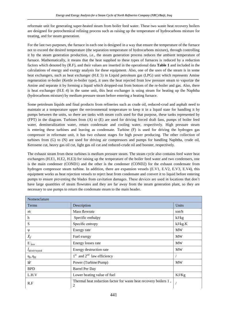
operating load, the energy losses results are illustrated in Figure 3, showed the same sequence of the energy
losses at real load. Condensers, boilers followed by the heat exchangers (H.E), atmospheric distillation tower
(ADT) and expansion vessels (E.V), which were forming a percentages of 29.79%, 24.93%, 14.33%, 10.59%,
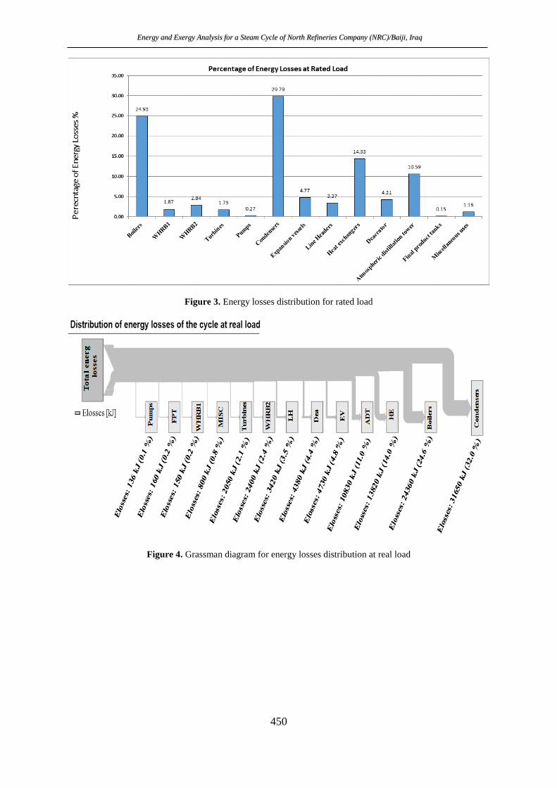
and 4.77%. Respectively. Also, Grassman diagrams Figure 4 and Figure 5 they illustrate the distribution of
energy losses and its percentage at real and rated operation loads for each equipment included in the study.The
1st-law efficiency for the whole cycle at real load and rated load are 36.27% and 38.63%, respectively. But
t s n s ( n r y n s) on’t v subst nt l m n n n v lu bl results in comparison with
2nd-law efficiency (Exergy efficiency).
Figure 2. Energy losses distribution for real load
Energy and Exergy Analysis for a Steam Cycle of North Refineries Company (NRC)/Baiji, Iraq
450
Figure 3. Energy losses distribution for rated load
Figure 4. Grassman diagram for energy losses distribution at real load

Energy and Exergy Analysis for a Steam Cycle of North Refineries Company (NRC)/Baiji, Iraq
451
Figure 5. Grassman diagram for energy losses distribution at rated load
Exergy destruction results presented in Table 5, for the two operation loads, reveals that at real load and rated
load, the highest exergy destructions are in the boilers, since the boilers are dominant upon all other
irreversibilities in the cycle. They destroy 28.32 MW and 34 MW which represent about 45.99% and 45.25% of
the total exergy destruction at real and rated load, respectively. The fact that boilers have the major of exergy
destruction in the cycle at various loads is due to the nature of the entropy generation (lost chances for doing
work) in it, because of the combustion process in the boilers and the heat transfer between finite temperature
differences.
Table 5. Exergy destruction at real and rated load
Real Load Rated load
Fuel mass flowrate (ton/h) 4.3 5.13
Total exergy Input (MW) 80.7 96.57
Work net (MW) 7 10.76
Co
mp
on
ent
Ex
erg
y
des
tru
ctio
n
(MW
)
Per
cen
t o
f
exer
gy
des
tru
ctio
n
(%)
2n
d-L
aw
effi
cien
cy (
%)
Ex
erg
y
des
tru
ctio
n
(MW
)
Per
cen
t o
f
exer
gy
des
tru
ctio
n
(%)
2n
d-L
aw
effi
cien
cy (
%)
Boilers 28.32 45.99 60.67 34 45.25 60.22
WHRB1 0.14 0.23 76.7 1.23 1.64 30.72
WHRB2 3.13 5.08 61.11 3.84 5.11 58.34
Turbines 9.57 15.54 33.85 10.92 14.53 34.53
Pumps 0.4 0.65 24.55 0.6 0.80 18.74
Condensers 8.4 13.64 48.65 9.54 12.70 49.44
Expansion vessels 1.23 2.00 14.93 1.54 2.05 19.9
Line Headers 2.74 4.45 95.76 3.41 4.54 95.48
Heat exchangers 3.68 5.98 65.14 4.85 6.45 60.96
Deaerator 0.8 1.30 80.76 0.91 1.21 81.08

Energy and Exergy Analysis for a Steam Cycle of North Refineries Company (NRC)/Baiji, Iraq
452
Atmos. distillation tower 2.91 4.73 / 3.88 5.16 /
Final product tanks 0.06 0.10 93.02 0.06 0.08 93
Miscellaneous uses 0.2 0.32 / 0.35 0.47 /
Total exergy destruction 61.58 100.00 75.13 100.00
2nd
-law efficiency (Cycle) 23.65% 22.60%
Barographs in Figure 6 and Figure 7 showed that after boilers and turbines have a considerable value for
exergy destructions, which reached a percentage of 15.54% at real load, and 14.53% at rated load, this is
because the various types of irreversibilities in turbines such as (expansion, friction, and leakages). Also,
condensers formed a percentage of 13.64% and 12.70% from total exergy destruction in the cycle at real and
rated load. Gr ssm n diagrams in Figure 8, Figure 9 also show the comparison in exergy destructions for
each equipment in the cycle for real and rated load, respectively.
Figure 6. Exergy destruction distribution for real load
Figure 7. Exergy destruction distribution for rated load

Energy and Exergy Analysis for a Steam Cycle of North Refineries Company (NRC)/Baiji, Iraq
453
Figure 8. Grassman diagram for exergy destruction at real load.
Figure 9. Grassman diagram for exergy destruction at rated load.
The effect of changing environment temperature on the exergy destruction and 2nd
-law efficiency for the main
components at real load are shown in Figure 10 and Figure 11, and for rated load in Figure 12 and Figure 13.It
can be noticed from these figures that the effect of changing the environment temperature is effectively occurs
in boilers and condensers. As the exergy destructions are increased for boilers but decrease for condensers when
the environment temperature is increased. On the other hand, the rest components in the cycle showed a small
response towards environment temperature changing as illustrated in the last figures. These results are matched
previous studies[6], [7]. The results of the exergy analysis also showed the effect of changing the environment
temperature on the 2nd-law efficiency of the cycle as in Figure 14. It can infer two things, the first is that the
2nd
-law efficiency for the real load is greater than that for rated load. This is true as the loading rate is higher in
case of rated load, in other words the exergy in (exergy expanded- equation (6) is high, and as a result of the
rating load increasing, the entropy generation in each equipment in the cycle will increase, causing increasing in
the total exergy destruction, i.e. the total exergy destruction increases as the entering exergy increase at rated
load, and gives a ratio of total exergy destroyed to the exergy expanded (equation (6)) greater than the ratio in
case of real load. The second is that the 2nd-law efficiency for the cycle at both rating loads is decreasing as the
environment temperature increased. This can be clearly noticed and satisfied particularly in the plant, especially
in hot weather (summer). The performance of plant equipment is decreases as the environment temperature
increase and this mainly happens for the equipment that reject heat (heat-output devices) to dead state such as
condensers, as illustrated graphically in Figure 11, and Figure 13.

Energy and Exergy Analysis for a Steam Cycle of North Refineries Company (NRC)/Baiji, Iraq
454
Figure 10. Effect of environment temperature on exergy destruction for main components at real load
Figure 11: Effect of environment temperature on 2nd-law efficiency for main components at real load
Figure 12: Effect of environment temperature on exergy destruction for main components at rated load

Energy and Exergy Analysis for a Steam Cycle of North Refineries Company (NRC)/Baiji, Iraq
455
Figure 13. Effect of environment temperature on 2nd-law efficiency for main components at rated load
Figure 14. Effect of environment temperature on 2nd-law efficiency of the cycle
CONCLUSIONS
The conclusions from this study are can be divided into two groups, the first are conclusions that related to
answering if this type of refinery steam cycle is verifying the concept of the energy and exergy analysis, and to
explain the results of this study if matches with the previous studies that deals with the power plant steam
cycles. The steam cycle had showed the applicability of the concepts of energy and exergy analysis and also, it
showed that its results matched with the previous studies that related to other power plants, this means the
recommendations, improvements, and upgrading systems of these studies can be applied to the steam generation
plants for refineries.
The second group, are conclusions that related to the operational results such as:
the condensers are the major source of energy losses in the steam cycle, and the boilers are the major
source of exergy destructions at any operation load.
At the both rating loads, the boilers showed a little increase in exergy destruction, while condensers
showed an obviously fluctuating in the exergy destruction.
The 2nd
-law efficiency for most equipment showed a bit decrease, but for the condensers showed a sharp
lowering as the environment temperature is increased.
The 2nd
-law efficiency for the cycle also affected by increasing the environment temperature, and it
showed a decreasing as the environment temperature is increasing at both rating loads.
Finally, the important note can be concluded through this study, is that for the low 2nd
-law efficiency devices, it
shows that there is a chance for doing an improvement in performance for such devices and should be kept in
mind in rehabilitation of the plant.

Energy and Exergy Analysis for a Steam Cycle of North Refineries Company (NRC)/Baiji, Iraq
456
REFERENCES
[1] M. Çengel, Yunus A. Boles, M l A. K noğlu, “T rmo yn m s_ n En n r n Appro . N nt
E t on,” 2019.
[2] K. V nk t sw rlu, “En n r n t rmo yn m s.” Fun m nt l n A v n Top s. 2021.
[3] I. D n r n M. A. Ros n, “Ex r y n lys s o st m pow r pl nts,” n Ex rgy, Elsevier, Pp. 325–354,
2021.
[4] M.T. .U,E. Yo n , .D. Pr y nto, I.A.M., n T uv q rr m n, “En r y n Ex r y An lys s o t m
Power Plant 3rd Unit PT PLN (PERSERO) Centre Unit Generation Tanjung Jati B Use BFP-T
Mo t on Cy l ,” E3 W b Conf., vol. 125, p. 13003, 2019, doi: 10.1051/e3sconf/201912513003.
[5] . A b tl n . C. K us k, “En r y n x r y n lys s o sup r r t l t rm l pow r pl nt t
v r ous lo on t ons un r onst nt n pur sl n pr ssur op r t on,” Appl. Therm. Eng., vol. 73, no.
1, pp. 51–65, Dec. 2014, doi: 10.1016/j.applthermaleng.2014.07.030.
[6] H. J. K l n M. H. Z n, “Pr t l n T or t l tu y to Improv t P r orm n o Pow r Un t
Used to Drive Gas Compressors for the North Gas Company–Ir q,” ZANCO J. Pur Appl. ., vol. 28, no.
2, 2016.
[7] G. R. A m n D. To r , “En r y n x r y n lys s o Mont z r t m Pow r Pl nt n Ir n,”
Renew. Sustain. Energy Rev., vol. 56, pp. 454–463, Apr. 2016, doi: 10.1016/j.rser.2015.11.074.
[8] . Kum r, D. Kum r, R. A. M mon, M. A. W ss n, n . A. M r, “En r y n Ex r y An lys s o Co l
F r Pow r Pl nt,” M r n Un v rs ty R s r Journ l o En n r n n T nolo y, vol. 37, no. 4. pp.
611–624, 2018, doi: 10.22581/muet1982.1804.13.
[9] K.D. P l nk r n R. K l , “En r y n Ex r y An lys s o t m n Pow r G n r t on Pl nt,” Int. J. En .
Res., vol. V5, no. 06, 2016. doi: 10.17577/ijertv5is060478.
[10] M. El lw, K. . Al D m , n A. l H. Att , “Ut l z n x r y n lys s n stu y n t p r orm n
o st m pow r pl nt t two r nt op r t on mo ,” Appl. T rm. En ., Vol. 150, Pp. 285–293, 2019.
doi: 10.1016/j.applthermaleng.2019.01.003.
[11] M.K. Mohammed, W.H. Al Doori, A.H. Jassim, T.K. Ibrahim, and A.T. Al- mm rr , “En r y n
x r y n lys s o t st m pow r pl nt b s on t t numb rs o w t r t r,” J. A v. R s.
Fluid Mech. Therm. Sci., vol. 56, no. 2, pp. 211–222, 2019.
[12] M.N. Ek , D.C. Ony j kw , O.C. Ilo j , C.I. Ez kw , n P.U. Akp n, “En r y n x r y v lu t on
o 220MW t rm l pow r pl nt,” N r. J. T nol., vol. 37, no. 1, p. 115, 2018, o :
10.4314/njt.v37i1.15.
[13] R.R.J. Al Doury, T.K. Salem, I.T. N zz l, R. Kum r, n M. z , “A nov l v lop
m t o to stu y t n r y/ x r y lows o bu l n s omp r to t tr t on l m t o ,” J. T rm. An l.
Calorim., Sep. 2020, doi: 10.1007/s10973-020-10203-1.
[14] M. Ameri, H. Mokhtari, and M. Bahram , “En r y, Ex r y, Ex r o onom n Env ronm nt l (4E)
Opt m z t on o L r t m Pow r Pl nt: A C s tu y,” 2016.
[15] M.J. Mor n, H. . , D. . . , and M. . Bailey, Principles of Engineering Thermodynamics, 8th editio.
London: Macmillan Education UK, 2015.