energy & environmental science - solarpaces
TRANSCRIPT

This journal is©The Royal Society of Chemistry 2018 Energy Environ. Sci.
Cite this:DOI: 10.1039/c8ee02341g
Thermal energy grid storage using multi-junctionphotovoltaics†
Caleb Amy, a Hamid Reza Seyf, b Myles A. Steiner, c Daniel J. Friedman c
and Asegun Henry *abde
As the cost of renewable energy falls below fossil fuels, the key barrier to widespread sustainable
electricity has become availability on demand. Energy storage can enable renewables to provide this
availability, but there is no clear technology that can meet the low cost needed. Thus, we introduce a
concept termed thermal energy grid storage, which in this embodiment uses multi-junction
photovoltaics as a heat engine. We report promising initial experimental results that suggest it is feasible
and could meet the low cost required to reach full penetration of renewables. The approach exploits an
important tradeoff between the realization of an extremely low cost per unit energy stored, by storing
heat instead of electricity directly, and paying the penalty of a lower round trip efficiency. To understand
why this tradeoff is advantageous, we first introduce a general framework for evaluating storage
technologies that treats round trip efficiency, as well as cost per unit energy and power, as variables.
Broader contextEven though the cost of solar and wind has dropped dramatically, the extent to which they can be used on the grid is limited by the need for some form ofenergy storage. As a result the storage problem has emerged as one of the most important technological hurdles to mitigating climate change. Current andfuture predictions for battery prices are too expensive to enable full penetration of renewables, which has necessitated a search for alternatives. Here, weintroduce a somewhat non-intuitive approach termed thermal energy grid storage, which stores electricity as heat and then converts it back to electricity ondemand. It is well known that the conversion of heat to electricity is thermodynamically limited and therefore results in a significant efficiency penalty.However, the storage of energy as heat instead of electricity can be 50–100� cheaper, and as a result the 15–40% efficiency penalty becomes a worthwhiletradeoff. In this article, we introduce a new embodiment that stores heat at extremely high temperatures (41900 1C) in order to maximize the conversionefficiency and it also enables usage of a different type of heat engine (i.e., specially designed photovoltaics) instead of a turbine, to achieve even lower cost.
Introduction
In the last decade the cost of electricity derived from renewables,i.e., solar photovoltaics (PV) and wind, has fallen dramatically,1,2
making renewables cheaper or competitive with fossil derivedelectricity in many locations. This is a remarkable achievement,but it is based purely on an assessment of the levelized cost perunit energy (LCOE) (i.e., the total cost divided by the lifetime
electricity output, $ per kWh-e). Although this is an importantquantity, it does not account for the fact that renewableelectricity is not necessarily available when desired, since it isinherently tied to the weather. Thus, providing energy ondemand remains a key necessity provided by existing fossil-based technologies. Consequently, as Denholm3,4 and others5–7
have shown, renewable penetration into the grid will be limitedto o10–15% without grid level storage. Thus, ‘‘the storageproblem’’ i.e., how to store/buffer energy at the grid scalecheaply, has emerged as one of the most important techno-logical barriers to decarbonization of the grid and mitigatingclimate change.
Currently the cheapest grid storage technology is pumpedhydroelectric storage (PHS), which has a high roundtrip effi-ciency (RTE) B80–90%, as well as a low cost per unit energy(CPE)B$60 per kWh-e and cost per unit power (CPP) B$1 per W-e.8
Here, CPE indicates all the costs related to the storage of energy(e.g. water reservoir), while CPP represents the costs that scale
a Department of Mechanical Engineering, Massachusetts Institute of Technology,
Cambridge, MA, 02139, USA. E-mail: [email protected] George W. Woodruff School of Mechanical Engineering, Georgia Institute of
Technology, Atlanta, GA, 30332, USAc National Renewable Energy Laboratory, Golden, CO, 80401, USAd School of Materials Science and Engineering, Georgia Institute of Technology,
Atlanta, GA, 30332, USAe Heat Lab, Georgia Institute of Technology, Atlanta, GA, 30332, USA
† Electronic supplementary information (ESI) available. See DOI: 10.1039/c8ee02341g
Received 10th August 2018,Accepted 14th November 2018
DOI: 10.1039/c8ee02341g
rsc.li/ees
Energy &EnvironmentalScience
PAPER
Ope
n A
cces
s A
rtic
le. P
ublis
hed
on 1
9 N
ovem
ber
2018
. Dow
nloa
ded
on 1
2/6/
2018
11:
18:4
4 A
M.
Thi
s ar
ticle
is li
cens
ed u
nder
a C
reat
ive
Com
mon
s A
ttrib
utio
n-N
onC
omm
erci
al 3
.0 U
npor
ted
Lic
ence
.
View Article OnlineView Journal

Energy Environ. Sci. This journal is©The Royal Society of Chemistry 2018
with power output (e.g. water pump/turbine). The issue with PH,and also compressed air energy storage (CAES), however, is thatthey are geographically limited, and in the case of PH the primelocations have already been exploited.7,9–11 Electrochemical bat-teries, on the other hand, have promising new chemistries,7,12
but it is unclear if any will displace Li-ion batteries whose pricescontinue to drop from $300–400 per kWh-e down to a predictedasymptote B$150 per kWh-e.7 There is significant concernnonetheless, that even this lower asymptote for Li-ion is stillnot cheap enough to enable the eventual 100% penetration ofrenewables. In this respect, alternative solutions to the storageproblem are needed, and it is likely that costs closer to$50 per kWh-e and below13,14 will be needed to eventuallyrealize 100% penetration and full abatement of CO2 emissionsfrom the stationary power sector. This low cost requirementarises from the fact that the storage cost, i.e., levelized cost ofstorage (LCOS), should be below the $0.06 per kWh currentaverage electricity price15 and 10 or more hours16 of storageare needed to reliably and cost-effectively supply the grid.
Thermal energy grid storage
In thinking about lower cost storage, one class of technologiesthat has not received much attention is thermal energy storage(TES). This is because the final form of energy needed iselectricity, necessitating the conversion of heat back to electri-city, which tends to occur at low efficiency (B35–40%) and highcost (B$1 per W-e) for conventional turbine-based heatengines. However, even though the low efficiency is off-putting, when one considers the entire economic proposition,it can actually prove quite attractive if new embodiments thatachieve somewhat higher RTEs or very low CPEs17 and/or CPPsare considered.
Several embodiments18,19 are under development involvingthe conversion of electricity to heat, which is then stored andlater converted back on demand, such that we have generallytermed this class of technologies thermal energy grid storage(TEGS) herein. What these various incarnations share is thestorage of heat, which is exploited to be as inexpensive aspossible and can be 1–2 orders of magnitude cheaper thanelectrochemical batteries. The simplest embodiment that isarguably closest to commercialization, is to use molten salt asis currently done in concentrated solar power (CSP) plants,20
except that one would need to replace the solar heat input withjoule heating. With this approach, one can today achieve aCPE o $100 per kWh-e,21 but the problem would be the lowRTE (B35–40%) and significant CPP (B$1 per W-e). A moreclever approach introduced by Laughlin18 involves the usage ofa heat pump instead of joule heating, which can in theoryalmost double the RTE to B72%, perhaps at similar CPP, andmakes TEGS a very attractive option. Other interesting andpotentially attractive embodiments also exist, but to determinethe best option, the value of RTE must be assessed with respectto CPE and CPP. It is therefore important to have a frameworkfor quantitatively evaluating the tradeoffs between RTE, CPEand CPP, which ultimately dictates the economics and value tothe grid. In what follows, we briefly introduce a simple
framework for assessing such tradeoffs, followed by an intro-duction and discussion of our own incarnation of TEGS, whichour analysis shows may be one of the few solutions to thestorage problem that is inexpensive enough to eventuallyenable a fully renewable grid.
A general framework for comparison of storage technologies
For a given storage technology, the total capital expenditure(CAPEX) can be thought of as a sum of two main components,CAPEX = CPE + CPP/t, where t is the time that the resource canbe discharged at maximum power. In the simplest terms,CAPEX is compared to the two primary unsaturated sourcesof revenue, namely capacity payments ($ per kW) paid annually,which scale with the power output promised/supplied, andarbitrage ($ per kW) earned annually, which is where the RTEplays a critical role. Notably, we do not assume any interventionfrom governments or otherwise to incentivize sustainableenergy despite the positive externalities so that these resultsstand on economic drivers alone. Sioshansi et al.4 have quanti-fied how much value a storage resource would receive fromarbitrage, as a function of the RTE and t, by using thePennsylvania New Jersey Maryland (PJM) grid as an example.Their work showed that there would be a diminishing increasein value for large t resources on the 2007 PJM grid and theyquantified how the value of storage changes with RTE, whichwe have used as an input in Fig. 1A. This plot shows that astorage technology with RTE r 36% would not have generatedany value from arbitrage on the 2007 PJM grid. Fundamentally,this is because the input energy must be purchased and there-fore the ratio between on-peak and off-peak pricing sets a lowerefficiency limit, Zmin, to earn arbitrage profit, as shown ineqn (1). That is, if a technology must buy three times as muchenergy as it sells, it must sell that energy for at least three timesthe purchase price to derive positive value from arbitrage.Because these devices cannot charge or discharge instanta-neously, the closer their efficiency is to Zmin, the less frequentlythey can profitably engage in arbitrage.
Zmin �Poffpeak
Ppeak(1)
To assess the value of RTE relative to CPE and CPP, we canuse the simple relation in eqn (2). Here, the CPP for zero netpresent value (NPV) is evaluated where total cost is equal tototal revenue earned during the system’s life, discounted withan internal rate of return (IRR) of 10%, denoted by r. This rate isbased on typical interest rates of energy storage systems,22
although the effect of variability is explored in extended dataTable S2, ESI.† Here, L is the lifetime in years, and Varb (RTE) isthe arbitrage value in $ per kW per year, which is a function ofRTE, as shown in Fig. 1A. The capacity payment (CP) isestimated based on the average net cost of new entry (NetCONE) of peaking gas turbines. Net CONE is the cost of apeaking gas turbine minus its anticipated energy and ancillaryrevenue, and therefore represents the capacity paymentneeded for it to break even.23,24 For the results in Fig. 1, CPis taken to be $95 per kW per year (see ESI†). Future revenue is
Paper Energy & Environmental Science
Ope
n A
cces
s A
rtic
le. P
ublis
hed
on 1
9 N
ovem
ber
2018
. Dow
nloa
ded
on 1
2/6/
2018
11:
18:4
4 A
M.
Thi
s ar
ticle
is li
cens
ed u
nder
a C
reat
ive
Com
mon
s A
ttrib
utio
n-N
onC
omm
erci
al 3
.0 U
npor
ted
Lic
ence
.View Article Online
This journal is©The Royal Society of Chemistry 2018 Energy Environ. Sci.
discounted with the factor a as shown in eqn (3), whichassumes revenue is accrued uniformly over time.
CPP ¼ L
aVarbðRTEÞ þ CPð Þ � t� CPE (2)
a ¼ rtert
ert � 1(3)
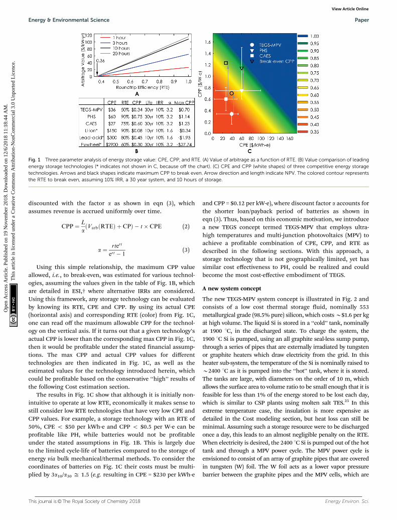
Using this simple relationship, the maximum CPP valueallowed, i.e., to break-even, was estimated for various technol-ogies, assuming the values given in the table of Fig. 1B, whichare detailed in ESI,† where alternative IRRs are considered.Using this framework, any storage technology can be evaluatedby knowing its RTE, CPE and CPP. By using its actual CPE(horizontal axis) and corresponding RTE (color) from Fig. 1C,one can read off the maximum allowable CPP for the technol-ogy on the vertical axis. If it turns out that a given technology’sactual CPP is lower than the corresponding max CPP in Fig. 1C,then it would be profitable under the stated financial assump-tions. The max CPP and actual CPP values for differenttechnologies are then indicated in Fig. 1C, as well as theestimated values for the technology introduced herein, whichcould be profitable based on the conservative ‘‘high’’ results ofthe following Cost estimation section.
The results in Fig. 1C show that although it is initially non-intuitive to operate at low RTE, economically it makes sense tostill consider low RTE technologies that have very low CPE andCPP values. For example, a storage technology with an RTE of50%, CPE o $50 per kWh-e and CPP o $0.5 per W-e can beprofitable like PH, while batteries would not be profitableunder the stated assumptions in Fig. 1B. This is largely dueto the limited cycle-life of batteries compared to the storage ofenergy via bulk mechanical/thermal methods. To consider thecoordinates of batteries on Fig. 1C their costs must be multi-plied by 3a10/a30 D 1.5 (e.g. resulting in CPE = $230 per kWh-e
and CPP = $0.12 per kW-e), where discount factor a accounts forthe shorter loan/payback period of batteries as shown ineqn (3). Thus, based on this economic motivation, we introducea new TEGS concept termed TEGS-MPV that employs ultra-high temperatures and multi-junction photovoltaics (MPV) toachieve a profitable combination of CPE, CPP, and RTE asdescribed in the following sections. With this approach, astorage technology that is not geographically limited, yet hassimilar cost effectiveness to PH, could be realized and couldbecome the most cost-effective embodiment of TEGS.
A new system concept
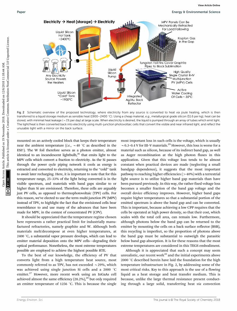
The new TEGS-MPV system concept is illustrated in Fig. 2 andconsists of a low cost thermal storage fluid, nominally 553metallurgical grade (98.5% pure) silicon, which costs B$1.6 per kgat high volume. The liquid Si is stored in a ‘‘cold’’ tank, nominallyat 1900 1C, in the discharged state. To charge the system, the1900 1C Si is pumped, using an all graphite seal-less sump pump,through a series of pipes that are externally irradiated by tungstenor graphite heaters which draw electricity from the grid. In thisheater sub-system, the temperature of the Si is nominally raised toB2400 1C as it is pumped into the ‘‘hot’’ tank, where it is stored.The tanks are large, with diameters on the order of 10 m, whichallows the surface area to volume ratio to be small enough that it isfeasible for less than 1% of the energy stored to be lost each day,which is similar to CSP plants using molten salt TES.25 In thisextreme temperature case, the insulation is more expensive asdetailed in the Cost modeling section, but heat loss can still beminimal. Assuming such a storage resource were to be dischargedonce a day, this leads to an almost negligible penalty on the RTE.When electricity is desired, the 2400 1C Si is pumped out of the hottank and through a MPV power cycle. The MPV power cycle isenvisioned to consist of an array of graphite pipes that are coveredin tungsten (W) foil. The W foil acts as a lower vapor pressurebarrier between the graphite pipes and the MPV cells, which are
Fig. 1 Three parameter analysis of energy storage value: CPE, CPP, and RTE. (A) Value of arbitrage as a function of RTE. (B) Value comparison of leadingenergy storage technologies (* indicates not shown in C, because off the chart). (C) CPE and CPP (white shapes) of three competitive energy storagetechnologies. Arrows and black shapes indicate maximum CPP to break even. Arrow direction and length indicate NPV. The colored contour representsthe RTE to break even, assuming 10% IRR, a 30 year system, and 10 hours of storage.
Energy & Environmental Science Paper
Ope
n A
cces
s A
rtic
le. P
ublis
hed
on 1
9 N
ovem
ber
2018
. Dow
nloa
ded
on 1
2/6/
2018
11:
18:4
4 A
M.
Thi
s ar
ticle
is li
cens
ed u
nder
a C
reat
ive
Com
mon
s A
ttrib
utio
n-N
onC
omm
erci
al 3
.0 U
npor
ted
Lic
ence
.View Article Online
Energy Environ. Sci. This journal is©The Royal Society of Chemistry 2018
mounted on an actively cooled block that keeps their temperaturenear the ambient temperature (i.e., B40 1C as described in theESI†). The W foil therefore serves as a photon emitter, almostidentical to an incandescent lightbulb,26 that emits light to theMPV cells which convert a fraction to electricity. As the Si passesthrough the power cycle piping network it cools as energy isextracted and converted to electricity, returning to the ‘‘cold’’ tankto await later recharging. Here, it is important to note that for thistemperature range, 25–33% of the light being converted is in thevisible spectrum, and materials with band gaps similar to orhigher than Si are envisioned. Therefore, these cells are arguablyjust PV cells, as opposed to thermophotovoltaic (TPV) cells. Forthis reason, we’ve elected to use the term multi-junction PV (MPV)instead of TPV, to highlight the fact that the envisioned cells bearresemblance to and use many of the advances that have beenmade for MPV, in the context of concentrated PV (CPV).
It should be appreciated that the temperature regime chosenhere represents a rather practical limit for industrially manu-factured refractories, namely graphite and W. Although bothmaterials melt/decompose at even higher temperatures, at2400 1C, a substantial vapor pressure develops, which can lead toemitter material deposition onto the MPV cells—degrading theiroptical performance. Nonetheless, the most extreme temperaturespossible are employed to achieve the highest possible RTE.
To the best of our knowledge, the efficiency of PV thatconverts light from a high temperature heat source, mostcommonly referred to as TPV, has not exceeded B29%, whichwas achieved using single junction Si cells and a 2000 1Cemitter.27 However, more recent work using an InGaAs cellachieved almost the same efficiency (28.2%),28 but only requiredan emitter temperature of 1256 1C. This is because the single
most important loss in such cells is the voltage, which is usuallyB0.3–0.4 V for III–V materials.29 However, this loss is worse for amaterial such as silicon, because of its indirect band gap, as wellas Auger recombination at the high photon fluxes in thisapplication. Given that this voltage loss tends to be almostconstant when practical devices are made (neglecting a smallbandgap dependence), it suggests that the most importantpathway to reaching higher efficiencies (440%) with a terrestriallight source is to utilize higher band gap materials than havebeen pursued previously. In this way, the rather fixed voltage lossbecomes a smaller fraction of the band gap voltage and theoverall device efficiency improves. However, higher band gapsrequire higher temperatures so that a substantial portion of theemitted spectrum is above the band gap and can be converted.This is important, because achieving a low CPP requires that thecells be operated at high power density, so that their cost, whichscales with the total cell area, can remain low. Furthermore,although photons below the band gap can be returned to theemitter by mounting the cells on a back surface reflector (BSR),this recycling is imperfect, so the proportion of photons abovethe band gap must be substantial to outweigh the parasiticbelow band gap absorption. It is for these reasons that the mostextreme temperatures are considered in this TEGS embodiment.
Although it is appreciated that such a concept may seemunrealistic, our recent work30 and the initial experiments above2000 1C described herein have laid the foundation for the hightemperature infrastructure in Fig. 2, by addressing some of themost critical risks. Key to this approach is the use of a flowingliquid as a heat storage and heat transfer medium. This isbecause, unlike the large thermal resistance present conduct-ing through a large solid, transferring heat via convection
Fig. 2 Schematic overview of the proposed technology, where electricity from any source is converted to heat via joule heating, which is thentransferred to a liquid storage medium as sensible heat (1900–2400 1C). Using a cheap material, e.g., metallurgical grade silicon ($1.6 per kg), heat can bestored, with minimal heat leakage (B1% per day) at large scale. When electricity is desired, the liquid is pumped through an array of tubes which emit light.The light/heat is then converted back into electricity using multi-junction photovoltaic cells that convert the visible and near infrared light, and reflect theunusable light with a mirror on the back surface.
Paper Energy & Environmental Science
Ope
n A
cces
s A
rtic
le. P
ublis
hed
on 1
9 N
ovem
ber
2018
. Dow
nloa
ded
on 1
2/6/
2018
11:
18:4
4 A
M.
Thi
s ar
ticle
is li
cens
ed u
nder
a C
reat
ive
Com
mon
s A
ttrib
utio
n-N
onC
omm
erci
al 3
.0 U
npor
ted
Lic
ence
.View Article Online

This journal is©The Royal Society of Chemistry 2018 Energy Environ. Sci.
minimizes thermal resistance. Usage of a solid or formation ofa solid (i.e., via phase change) can become problematic becausea sensible heat discharge from a solid will inherently cause aconductive resistance to build up, which will lower the poweroutput and efficiency over time. Besides direct cost implica-tions, this issue is undesirable for grid operation becausecapacity payments are based on a rated power that can besupplied/promised (see ESI†). However, since a liquid/fluid canbe pumped, it enables straightforward designs that can achievea steady state power output and RTE.
For the MPV power cycle, some of the important system levelconsiderations have been addressed in previous work by Seyfand Henry,31 such as the need for the power cycle to be large(MW scale, with length scales B10 m) in order to overcome thelosses associated with heat leakage to the environment byminimizing the ratio of surface area to volume. Their priorwork also identified the BSR reflectivity, or more specifically thenet amount of below band gap cell absorption, as the mostcritical parameter. However, while their initial predictions forthe cell efficiency are theoretically justified, they do not fullycapture the realistic voltage losses that tend to occur in realcells. Thus, a more realistic consideration of practical celllosses would drive the system towards operation at muchhigher temperatures than their initial work indicated,31 as willbe discussed in more detail in the next section. Nonetheless,the MPV cells considered herein are still envisioned to incor-porate a BSR, but for this temperature regime, higher band gapmaterials as well as multiple junctions are expected to beoptimal. Furthermore, by using cells grown on GaAs as opposedto InP substrates and by using hydride vapor phase epitaxy(HVPE) instead of metal–organic chemical vapor deposition(MOCVD), the cell costs could be much lower than estimated.
One critical question that arises with the TEGS-MPVapproach, however, is why MPV is chosen as the heat engineinstead of a turbine, which could likely be more efficient atlower temperatures. There are three reasons for this: (1) turbinesthat take an external heat input and operate at high efficiencies(450%) do not currently exist. Although it may be possible todevelop such a system, a large barrier to commercial deploymentexists, as it would require a large OEM to undertake an expensive(4$100 million) development effort for a high-risk application.On the other hand, existing III–V cell manufacturers are posi-tioned to facilitate the commercialization and deployment of thedescribed MPV power cycle with much less investment. (2) Thecost of our proposed MPV system can be much lower than that ofa turbine. (3) The speed with which turbine-based heat enginescan ramp from zero to full power is on the order of tens ofminutes to an hour. However, with this TEGS-MPV approach, asis illustrated in Fig. 2, the MPV modules can be actuated in andout of the light on the order of seconds, which could providemuch greater value to the grid via load following, therebyincreasing revenue.
Modeling and experimental results on feasibility
One inescapable component needed to realize the TEGS-MPVsystem is the storage medium tank. If there is no conceivable
way to make the tanks, then there is no path towards realizingthe system. Using a liquid storage medium requires that thetank be impermeable, and the options for materials at thesetemperatures are severely limited. One of the only cost effectiveoptions is graphite, but it would be infeasible to fabricate theentire B10 m diameter tank from a single monolithic piece.This necessitates that the tank be formed from sections, withsealed interfaces that do not leak.
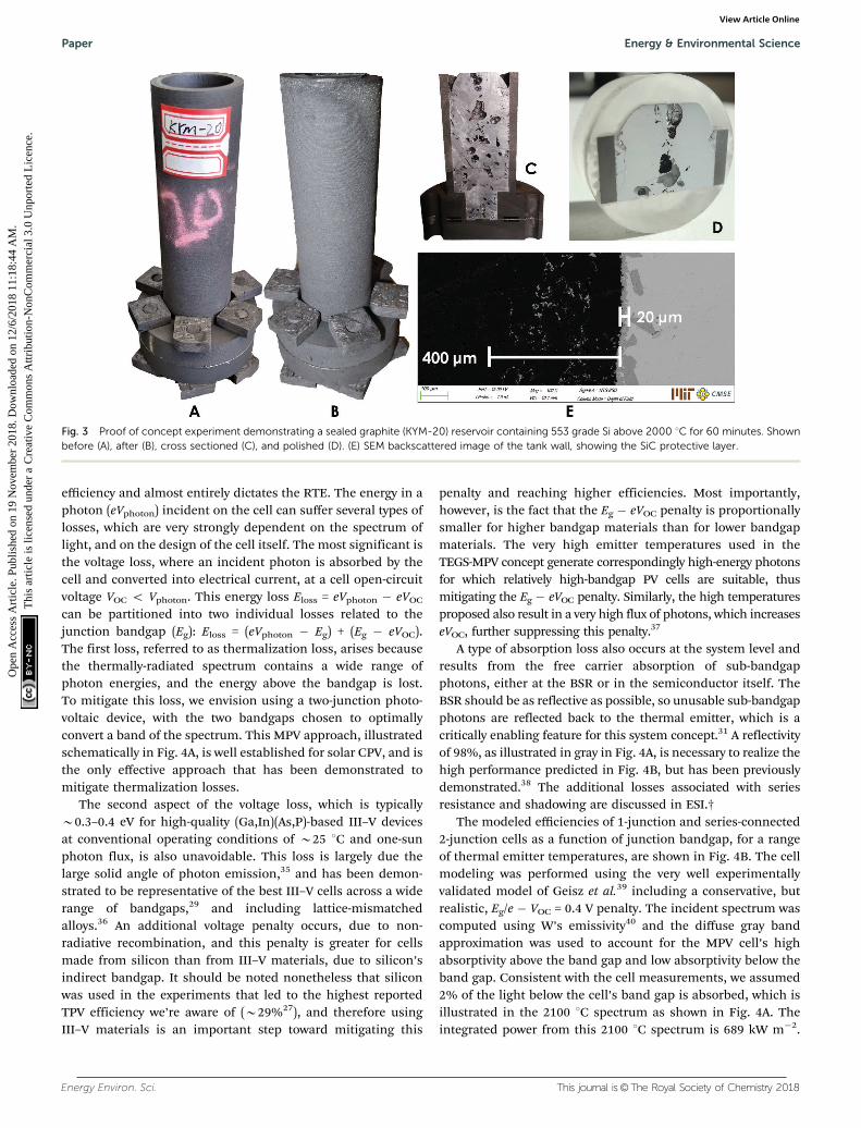
A first and highly encouraging result that suggests thisproblem can be easily and cost effectively solved is shown inFig. 3. In this experiment, a dense (1.85 g cc�1) graphite (KYM-20)miniature ‘‘tank’’ filled with 553 grade Si was heated above2000 1C for 60 minutes. The tank was made from two sectionsand sealed with a thin grafoil face seal that was compressed bycarbon fiber composite (CFC) threaded rods and nuts. Thetank was insulated with graphite felt and aluminum silicateinsulation inside a quartz tube, under high purity argon gas(o1 � 10�6 atm O2). The tank was heated by induction and itstemperature was measured using a C-type thermocouple. It is wellknown that graphite and Si(l) react to form SiC,32 and a protectiveSiC scale that prevents further reaction can form, if the graphitehas the right microstructure. In this experiment, as shown inFig. 3E, Si penetrated the graphite tank approximately 400 mm,and created a dense 20 mm thick SiC layer at the interface,preventing further penetration. Initial experiments showed thatif a thicker grafoil seal is used, the expansive reaction could breakapart the entire ‘‘tank’’. Thus, this preliminary result is rathernon-trivial, as it offers initial proof and confidence that Si can becontained at these temperatures in a multi-section tank.
Another feasibility issue concerns the need to pump liquidSi at temperatures as high as 2400 1C. On this issue, recentexperiments by Amy et al.30 have shown that it is feasible to usebrittle ceramics as mechanical pumps, as they pumped liquidtin at temperatures up to 1400 1C. Here, the temperature isB1000 1C higher, which would be a major concern for infra-structure made from solid metal components. However, forceramics and refractories, such as graphite, this is much less ofa concern, since the materials tend to be covalently bonded andtherefore tend to exhibit weak dependence of their mechanicalproperties on temperature. In fact, the strength of graphiteactually increases with temperature, up to 2600 1C.33 For thesereasons, although pumping at 2400 1C has not been donebefore, the testing above 2000 1C and pumping30 at 1400 1Crenders the notion now feasible, as there are no obvious issuesthat should prevent operation at the higher temperatures.
Another potential issue with the TEGS-MPV system is thatthe heater efficiency is a non-trivial matter, since it wouldrequire power conditioning electronics that could have sub-stantial losses that ultimately detract from the RTE. This issueis discussed in more detail in ESI,† but the conclusion is thatexisting power electronics can supply the necessary input at lowcost with less than 1% parasitic loss.34 This loss is small andalmost negligible, which shifts our focus to the primary loss inthe system, which occurs in the MPV power block.
The PV cell which converts photons radiated from thethermal emitter to electricity plays a crucial role in the system
Energy & Environmental Science Paper
Ope
n A
cces
s A
rtic
le. P
ublis
hed
on 1
9 N
ovem
ber
2018
. Dow
nloa
ded
on 1
2/6/
2018
11:
18:4
4 A
M.
Thi
s ar
ticle
is li
cens
ed u
nder
a C
reat
ive
Com
mon
s A
ttrib
utio
n-N
onC
omm
erci
al 3
.0 U
npor
ted
Lic
ence
.View Article Online
Energy Environ. Sci. This journal is©The Royal Society of Chemistry 2018
efficiency and almost entirely dictates the RTE. The energy in aphoton (eVphoton) incident on the cell can suffer several types oflosses, which are very strongly dependent on the spectrum oflight, and on the design of the cell itself. The most significant isthe voltage loss, where an incident photon is absorbed by thecell and converted into electrical current, at a cell open-circuitvoltage VOC o Vphoton. This energy loss Eloss = eVphoton � eVOC
can be partitioned into two individual losses related to thejunction bandgap (Eg): Eloss = (eVphoton � Eg) + (Eg � eVOC).The first loss, referred to as thermalization loss, arises becausethe thermally-radiated spectrum contains a wide range ofphoton energies, and the energy above the bandgap is lost.To mitigate this loss, we envision using a two-junction photo-voltaic device, with the two bandgaps chosen to optimallyconvert a band of the spectrum. This MPV approach, illustratedschematically in Fig. 4A, is well established for solar CPV, and isthe only effective approach that has been demonstrated tomitigate thermalization losses.
The second aspect of the voltage loss, which is typicallyB0.3–0.4 eV for high-quality (Ga,In)(As,P)-based III–V devicesat conventional operating conditions of B25 1C and one-sunphoton flux, is also unavoidable. This loss is largely due thelarge solid angle of photon emission,35 and has been demon-strated to be representative of the best III–V cells across a widerange of bandgaps,29 and including lattice-mismatchedalloys.36 An additional voltage penalty occurs, due to non-radiative recombination, and this penalty is greater for cellsmade from silicon than from III–V materials, due to silicon’sindirect bandgap. It should be noted nonetheless that siliconwas used in the experiments that led to the highest reportedTPV efficiency we’re aware of (B29%27), and therefore usingIII–V materials is an important step toward mitigating this
penalty and reaching higher efficiencies. Most importantly,however, is the fact that the Eg � eVOC penalty is proportionallysmaller for higher bandgap materials than for lower bandgapmaterials. The very high emitter temperatures used in theTEGS-MPV concept generate correspondingly high-energy photonsfor which relatively high-bandgap PV cells are suitable, thusmitigating the Eg � eVOC penalty. Similarly, the high temperaturesproposed also result in a very high flux of photons, which increaseseVOC, further suppressing this penalty.37
A type of absorption loss also occurs at the system level andresults from the free carrier absorption of sub-bandgapphotons, either at the BSR or in the semiconductor itself. TheBSR should be as reflective as possible, so unusable sub-bandgapphotons are reflected back to the thermal emitter, which is acritically enabling feature for this system concept.31 A reflectivityof 98%, as illustrated in gray in Fig. 4A, is necessary to realize thehigh performance predicted in Fig. 4B, but has been previouslydemonstrated.38 The additional losses associated with seriesresistance and shadowing are discussed in ESI.†
The modeled efficiencies of 1-junction and series-connected2-junction cells as a function of junction bandgap, for a rangeof thermal emitter temperatures, are shown in Fig. 4B. The cellmodeling was performed using the very well experimentallyvalidated model of Geisz et al.39 including a conservative, butrealistic, Eg/e � VOC = 0.4 V penalty. The incident spectrum wascomputed using W’s emissivity40 and the diffuse gray bandapproximation was used to account for the MPV cell’s highabsorptivity above the band gap and low absorptivity below theband gap. Consistent with the cell measurements, we assumed2% of the light below the cell’s band gap is absorbed, which isillustrated in the 2100 1C spectrum as shown in Fig. 4A. Theintegrated power from this 2100 1C spectrum is 689 kW m�2.
Fig. 3 Proof of concept experiment demonstrating a sealed graphite (KYM-20) reservoir containing 553 grade Si above 2000 1C for 60 minutes. Shownbefore (A), after (B), cross sectioned (C), and polished (D). (E) SEM backscattered image of the tank wall, showing the SiC protective layer.
Paper Energy & Environmental Science
Ope
n A
cces
s A
rtic
le. P
ublis
hed
on 1
9 N
ovem
ber
2018
. Dow
nloa
ded
on 1
2/6/
2018
11:
18:4
4 A
M.
Thi
s ar
ticle
is li
cens
ed u
nder
a C
reat
ive
Com
mon
s A
ttrib
utio
n-N
onC
omm
erci
al 3
.0 U
npor
ted
Lic
ence
.View Article Online

This journal is©The Royal Society of Chemistry 2018 Energy Environ. Sci.
The fraction of this incident power absorbed by the cell,including sub-bandgap absorption due to imperfect 98% sub-bandgap reflectivity, depends on the cell’s bottom-junctionbandgap Eg,bot, and is 150 kW m�2 for Eg,bot = 1.4 eV and367 kW m�2 for Eg,bot = 1.0 eV. Every above-bandgap photonwhich is absorbed is assumed to be collected as current, anidealization that can later be replaced with actual measured cellperformance. Nonetheless, this assumption is close to themeasured performance of many previous cells. The cell’scurrent–voltage characteristics and maximum-power outputare then computed, with junction voltages adding for multi-junction devices. The ratio of this power output to theintegrated net input power, including a static 4.6 kW m�2
convection loss (see ESI†) through the inert gas between theemitter and cell, yields the net cell efficiency. Practical cellefficiencies are typically B85–90% of the efficiencies modeledat this level of idealization.39 Fig. 4B shows that practicalefficiencies of well over 40% are achievable for 1-junction cells,and Z50% is possible with 2-junction cells. For the 2100 1Cemitter, the optimal junction bandgaps are roughly 1.0–1.2 eVfor the 1-junction cell, and {1.2, 1.0} eV to {1.4, 1.2} eV for the{top, bottom} junctions of a 2-junction cell.
As described in further detail in the ESI,† a dual junction PVdevice could be fabricated using the inverted metamorphicmultijunction (IMM) cell architecture. The cell is grown on aGaAs substrate, but first the lattice constant is slowly increasedby means of a compositionally step-graded buffer so as toenable strain-free deposition of (Al)GaInAs films with bandgapsof 1.0–1.2 eV. Years of development of lattice-mismatchedepitaxy, and the IMM cell specifically, have lead to defectdensities o106 cm�2 and Woc o 0.4 V,36 despite the mismatch
with the substrate. The junctions in the tandem are separatedby a tunnel diode.
Cost estimation
The major advantages of TEGS-MPV over other grid level energystorage technologies are its expected low cost and geographi-cally flexibility. Thus, it is important to demonstrate the basisof the cost estimates provided, as summarized in Fig. 5. As anominal design point, we considered a 100 MW-e outputsystem with 10 hours of storage. The CPE includes the storagemedium, tank, insulation, auxiliary components, and construc-tion, using a similar procedure to Glatzmaier17 and Wilk et al.41
The CPP includes the heater, MPV cells, inverter, emitter, insula-tion, construction, and cooling system. Following a summary ofthe basis of these costs, the ESI† describes the methodology usedto generate these estimates and associated sources.
In the base case, 553 grade (98.5% pure) Si is used at amarket price of $1.60 per kg. The tank wall is made fromisostatic molded graphite (e.g. KYM-20) of density 1.8 g cm�3, ata cost of $7 per kg based on multiple quotes from largesuppliers. The insulation for all components consists of gra-phite felt ($7000 per m3), surrounded by an aluminum silicateblanket, surrounded by a fiberglass blanket. The cost of thegraphite felt dominates, so its use is constrained to the regionabove the 1350 1C temperature limit of aluminum silicate.Construction costs are based on the cost of molten-salt CSPplants,41 plus the labor cost of assembling additional compo-nents as detailed in ESI.† The cost of the heater includesgraphite heating elements, graphite pipes and headers, insula-tion, and inert containment. The MPV power block containssimilar elements, although the cost is dominated by the
Fig. 4 (A) Illustration of absorption from a 2100 1C thermal emitter in a two-junction PV cell. The cell reflectivity for photon energies below the bandgapis assumed to be 98%, meaning 98% of sub-bandgap photons (gray color) are returned to the source, while 2% (black in the figure) are absorbed in theback reflector. ‘‘TJ’’ indicates the tunnel junction series interconnect. (B)-(i) Modeled efficiencies of 1- and 2-junction PV cells for 1900–2400 1C emittertemperatures as a function of (bottom) junction bandgap. For 2-junction cells, the top-junction bandgap is selected to give the highest efficiency for agiven bottom-junction bandgap. (ii) Optimal top-junction bandgap.
Energy & Environmental Science Paper
Ope
n A
cces
s A
rtic
le. P
ublis
hed
on 1
9 N
ovem
ber
2018
. Dow
nloa
ded
on 1
2/6/
2018
11:
18:4
4 A
M.
Thi
s ar
ticle
is li
cens
ed u
nder
a C
reat
ive
Com
mon
s A
ttrib
utio
n-N
onC
omm
erci
al 3
.0 U
npor
ted
Lic
ence
.View Article Online

Energy Environ. Sci. This journal is©The Royal Society of Chemistry 2018
$0.08 per W-e inverter cost,1 $0.10 per W-e MPV cell cost, and$0.07 per W-e cooling cost. This cell cost is based on anassumed power density of 100 kW m�2 and a cell cost31 of$10 000 per m2. In reality, this cost may be much lower if theaforementioned cell manufacturing developments are realized(i.e., GaAs substrates and HVPE). Similarly, an alternativeembodiment of interest is Fe partially or fully replacing Si asthe storage medium. In this scenario, the cost of the mediumbecomes extremely low if one uses scrap steel, and the othertank costs, especially insulation and construction, dominate.In this less conservative lower cost case, we also assume a lowergrade extruded ($2 per kg) graphite is used for the tank and ahigher heat loss of 2% per day, instead of 1%. The effect ofthese changes is shown in Fig. 5.
Discussion
Based on the analysis presented herein, the TEGS-MPV conceptoffers an attractive value proposition as a grid storage technol-ogy. In this study, a simplified framework was presented thatenables one to compare and assess the economic viability ofnew grid storage solutions. Of particular importance is thetradeoff between RTE, CPE and CPP. The analysis showed thatsome TEGS embodiments have the potential to significantlyexceed the expected 36% RTE lower bound,4 while also achiev-ing extremely low CPE and CPP. A new TEGS embodiment wasthen presented based on ultra-high temperature storage media,in liquid form, and that uses MPV as the converter. This newapproach has several noteworthy benefits including the abilityto reach Z50% RTE with a CPP o $0.5 per W-e, and thepotential to offer load following capabilities to grid operators.These benefits strongly suggest that, if realized, the TEGS-MPVapproach could be one of the few grid storage approaches thatare inexpensive enough to enable the eventual 100% penetra-tion of renewables onto the grid. However, there are a number
of practical challenges that must be overcome to realize theTEGS-MPV approach. Most notably, a prototype system isneeded to confirm that the storage medium can be reliablypumped without leaks and that the MPV cells can be reliablyfabricated and perform as modeled under realistic conditions.Towards this end, two first experiments were presented thatstrongly suggest some of the most risky aspects of the TEGS-MPV system can be resolved. First, experiments above 2000 1Cshowed that a tank for Si with dimensions on the order of 10 mcould conceivably be made out of smaller (i.e., order 1 m)sections that are sealed and bolted together. These experimentsshowed that grafoil gaskets can be used to successfully sealagainst liquid silicon without leakage. Additionally, the mostimportant property of the MPV cells is their absorptivity forbelow band gap radiation. Calculations herein assumed thisparasitic absorption to be 2% and measurements of the reflec-tivity of cells that were backed by a gold or silver layer haveconfirmed that this is indeed possible.38 For these reasons, itseems feasible, although challenging, to realize the cost andperformance described herein (i.e., CPE o $40 per kWh-e,CPP o $0.4 per W-e, and RTE Z 50%) using TEGS-MPV.
Conflicts of interest
There are no conflicts to declare.
Acknowledgements
This work was authored in part by the National RenewableEnergy Laboratory, operated by Alliance for Sustainable Energy,LLC, for the U.S. Department of Energy (DOE) under ContractNo. DE-AC36-08GO28308. Funding provided by the U.S. Depart-ment of Energy Office of Energy Efficiency and RenewableEnergy Solar Energy Technologies Office. The views expressedherein do not necessarily represent the views of the DOE or the
Fig. 5 (A) Estimated CPE of TEGS-MPV in the base case and low cost case. (B) Estimated CPP of TEGS-MPV in the base case and low cost case. The lowcost case assumes scrap steel as the storage medium, MPV cell cost reduction and higher power density, and low-cost graphite.
Paper Energy & Environmental Science
Ope
n A
cces
s A
rtic
le. P
ublis
hed
on 1
9 N
ovem
ber
2018
. Dow
nloa
ded
on 1
2/6/
2018
11:
18:4
4 A
M.
Thi
s ar
ticle
is li
cens
ed u
nder
a C
reat
ive
Com
mon
s A
ttrib
utio
n-N
onC
omm
erci
al 3
.0 U
npor
ted
Lic
ence
.View Article Online

This journal is©The Royal Society of Chemistry 2018 Energy Environ. Sci.
U.S. Government. The U.S. Government retains and the pub-lisher, by accepting the article for publication, acknowledgesthat the U.S. Government retains a nonexclusive, paid-up,irrevocable, worldwide license to publish or reproduce thepublished form of this work, or allow others to do so, for U.S.Government purposes.
References
1 R. Fu, D. Feldman, R. Margolis, M. Woodhouse andK. Ardani, U.S. Solar Photovoltaic System Cost Benchmark:Q1 2017, Report No. NREL/TP-6A20-68925 (National Renew-able Energy laboratory, 2017).
2 T. Stehly, D. Heimiller and G. Scott, 2016 Cost of WindEnergy Review, Report No. NREL/TP-6A20-70363, (NationalRenewable Energy Laboratory, 2017).
3 P. Denholm, J. Jorgenson, M. Hummon, T. Jenkin andD. Palchak, The Value of Energy Storage for Grid Applica-tions, Report No. NREL/TP-6A20-58465, 45 (National Renew-able Energy Laboratory, 2013).
4 R. Sioshansi, P. Denholm, T. Jenkin and J. Weiss, Estimat-ing the value of electricity storage in PJM: Arbitrage andsome welfare effects, Energ. Econ., 2009, 31, 269–277, DOI:10.1016/j.eneco.2008.10.005.
5 K. Bradbury, L. Pratson and D. Patino-Echeverri, Economicviability of energy storage systems based on price arbitragepotential in real-time U.S. electricity markets, Appl. Energy,2014, 114, 512–519, DOI: 10.1016/j.apenergy.2013.10.010.
6 A. H. Slocum, et al., Ocean Renewable Energy Storage(ORES) System: Analysis of an Undersea Energy StorageConcept, Proc. IEEE, 2013, 101, 906–924, DOI: 10.1109/JPROC.2013.2242411.
7 O. Schmidt, A. Hawkes, A. Gambhir and I. Staffell, The futurecost of electrical energy storage based on experience rates,Nat. Energy, 2017, 6, 17110, DOI: 10.1038/nenergy.2017.110.
8 S. Schoenung, Energy Storage Systems Cost Update ReportNo. SAND2011-2730 (Sandia National Laboratories 2011).
9 R. Urıa-Martınez, P. W. O’Connor and M. M. Johnson, 2014Hydropower Market Report, (DOE EERE Wind and WaterPower Technologies Office, 2015).
10 R. Bowers, Energy storage and renewables beyond wind,hydro, solar make up 4% of U.S. power capacity, (U.S.Energy Information Administration, 2017).
11 Challenges and Opportunities For New Pumped StorageDevelopment. (NHA’s Pumped Storage Development Coun-cil, 2012).
12 M. Park, J. Ryu, W. Wang and J. Cho, Material design andengineering of next-generation flow-battery technologies, Nat.Rev. Mater., 2016, 2, 16080, DOI: 10.1038/natrevmats.2016.80.
13 Y.-M. Chiang, L. Su, M. S. Pan and Z. Li, Lowering the Baron Battery Cost, Joule, 2017, 1, 212–219, DOI: 10.1016/j.joule.2017.09.015.
14 Z. Li, et al., Air-Breathing Aqueous Sulfur Flow Battery forUltralow-Cost Long-Duration Electrical Storage, Joule, 2017,1, 306–327, DOI: 10.1016/j.joule.2017.08.007.
15 S. M. Schoenung and W. V. Hassenzahl, Long- vs. Short-Term Energy Storage Technologies Analysis, Report No.SAND2003-2783 (Sandia National Laboratories Albuquer-que, New Mexico, 2003).
16 C. Budischak, et al., Cost-minimized combinations of windpower, solar power and electrochemical storage, poweringthe grid up to 99.9% of the time, J. Power Sources, 2013, 225,60–74, DOI: 10.1016/j.jpowsour.2012.09.054.
17 G. Glatzmaier, Developing a Cost Model and Methodologyto Estimate Capital Costs for Thermal Energy Storage.(National Renewable Energy Laboratory, 2011).
18 R. B. Laughlin, Pumped thermal grid storage with heatexchange, J. Renewable Sustainable Energy, 2017, 9, 044103,DOI: 10.1063/1.4994054.
19 A. Dietrich, Assessment of Pumped Heat Electricity Storage Systemsthrough Exergoeconomic Analyses, University of Darmstadt, 2017.
20 U. Pelay, L. Luo, Y. Fan, D. Stitou and M. Rood, Thermalenergy storage systems for concentrated solar power plants,Renewable Sustainable Energy Rev., 2017, 79, 82–100, DOI:10.1016/j.rser.2017.03.139.
21 C. S. Turchi, J. Vidal and M. Bauer, Molten salt power towersoperating at 600–650 1C: Salt selection and cost benefits, Sol.Energy, 2018, 164, 38–46, DOI: 10.1016/j.solener.2018.01.063.
22 Lazard’s Levelized Cost of Storage Analysis – Version 3.0.(Lazard and Enovation Partners, 2017).
23 2018/2019 RPM Base Residual Auction Planning PeriodParameters, 14 (PJM, 2015).
24 T. Jenkin, P. Beiter and R. Margolis, Capacity Payments inRestructured Markets under Low and High PenetrationLevels of Renewable Energy, Report No. NREL/TP-6A20-65491, (National Renewable Energy Laboratory, 2016).
25 R. Sioshansi and P. Denholm, The Value of ConcentratingSolar Power and Thermal Energy Storage, IEEE Trans. Sustain.Energy, 2010, 1, 173–183, DOI: 10.1109/TSTE.2010.2052078.
26 A. Leroy, et al., Combined selective emitter and filter forhigh performance incandescent lighting, Appl. Phys. Lett.,2017, 111, 094103, DOI: 10.1063/1.4989522.
27 R. M. Swanson, 1978 International Electron Devices Meeting,70–73.
28 Z. Omair, et al., Conference on Lasers and Electro-Optics.AW3O.7, Optical Society of America.
29 R. R. King, et al., 40% efficient metamorphic GaInP/GaInAs/Ge multijunction solar cells, Appl. Phys. Lett., 2007, 90, 183516,DOI: 10.1063/1.2734507.
30 C. Amy, et al., Pumping liquid metal at high temperatures up to1,673 kelvin, Nature, 2017, 550, 199–203, DOI: 10.1038/nature24054.
31 H. R. Seyf and A. Henry, Thermophotovoltaics: a potentialpathway to high efficiency concentrated solar power, EnergyEnviron. Sci., 2016, 9, 2654–2665, DOI: 10.1039/C6EE01372D.
32 S. Kawanishi, T. Yoshikawa and T. Tanaka, EquilibriumPhase Relationship between SiC and a Liquid Phase in theFe–Si–C System at 1523–1723 K, Mater. Trans., 2009, 50,806–813, DOI: 10.2320/matertrans.MRA2008404.
33 C. Malmstrom, R. Keen and L. Green, Some MechanicalProperties of Graphite at Elevated Temperatures, J. Appl.Phys., 1951, 22, 593–600, DOI: 10.1063/1.1700013.
Energy & Environmental Science Paper
Ope
n A
cces
s A
rtic
le. P
ublis
hed
on 1
9 N
ovem
ber
2018
. Dow
nloa
ded
on 1
2/6/
2018
11:
18:4
4 A
M.
Thi
s ar
ticle
is li
cens
ed u
nder
a C
reat
ive
Com
mon
s A
ttrib
utio
n-N
onC
omm
erci
al 3
.0 U
npor
ted
Lic
ence
.View Article Online

Energy Environ. Sci. This journal is©The Royal Society of Chemistry 2018
34 T. Nagel, S. Kosik and D. Fuhlbohm, How SCR Controllers HelpBoost Energy Efficiency, Report No. ENG-SCRControllers-EnergyEfficiency-270-01 11.15, (Advanced Energy Industries,Inc., 2015).
35 E. D. Kosten, J. H. Atwater, J. Parsons, A. Polman and H. A.Atwater, Highly efficient GaAs solar cells by limiting light emissionangle, Light: Sci. & Appl., 2013, 2, e45, DOI: 10.1038/lsa.2013.1.
36 R. M. France, F. Dimroth, T. J. Grassman and R. R. King,Metamorphic epitaxy for multijunction solar cells, MRSBull., 2016, 41, 202–209, DOI: 10.1557/mrs.2016.25.
37 Concentrator Photovoltaics, ed. Antonio L. Luque and AndreevViacheslav, Springer, Berlin Heidelberg, 2007, pp. 175–197.
38 T. Xiao, et al., Conference on Lasers and Electro-Optics.ATu1K.2, Optical Society of America.
39 J. F. Geisz, et al., Generalized Optoelectronic Model of Series-Connected Multijunction Solar Cells, IEEE J. Photovolt., 2015,5, 1827–1839, DOI: 10.1109/JPHOTOV.2015.2478072.
40 W. W. Coblentz, The Reflecting Power of Various Metals,Bulletin of the Bureau of Standards, Washington,1910.
41 G. Wilk, A. DeAngelis and A. Henry, Estimating the cost ofhigh temperature liquid metal based concentrated solarpower, J. Renewable Sustainable Energy, 2018, 10, 023705,DOI: 10.1063/1.5014054.
Paper Energy & Environmental Science
Ope
n A
cces
s A
rtic
le. P
ublis
hed
on 1
9 N
ovem
ber
2018
. Dow
nloa
ded
on 1
2/6/
2018
11:
18:4
4 A
M.
Thi
s ar
ticle
is li
cens
ed u
nder
a C
reat
ive
Com
mon
s A
ttrib
utio
n-N
onC
omm
erci
al 3
.0 U
npor
ted
Lic
ence
.View Article Online