ene 240 class10 - kmuttwebstaff.kmutt.ac.th/~werapon.chi/m2_3/1_2017/ene_240... · 2017-11-09 ·...
TRANSCRIPT

1
1
Digital Signal• Binary or two stages:
“0” (Low voltage 0 - 3 V)“1” (High voltage 4 - 5 V)( g g )
• Binary digit is called “bit”. • Group of bits is called “word”.
• 8-bit group is called “byte”.• For N-bit base-2 number = 2N levels
2
2N-1 … 23 22 21 20
01…000111 LeastSignificantBit (LSB)
MostSignificantBit (MSB)
N bits

2
Analog-to-Digital Process
2 Steps
• Sampling and Holding (S/H)• Quantizing and Encoding (Q/E)
3
Shannon-Nyquist Sampling Theorem
• Discrete time enough to avoid aliasingf 2 ffsampling 2fmax
Voltage (V)
1 (01)
2 (10)
3 (11)Reconstruction
Qua
ntiz
atio
n
4
1/fsampling
Time (s)0 (00)
Sampling
Q
Clock

3
Sampling and Hold
• Holding signal benefits the accuracy of the A/Daccuracy of the A/D conversion.
• Minimum sampling rate should be at least twice the highest data frequency of the analog signal
5
Resolution• Quantization error rounding
Input Voltage(V)
Binary Word(4 bits)
Digital Signal
(V) (4 bits)
0.0 0 0 0 0
0.1 0 0 0 1k
k
6Step size for N-bit code, k = Vreference / 2N
0.2 0 0 1 0

4
Resolution (Cont’d)Ex Signal from 800-1500 mV may be converted
to 8-bit binary codes starting from 01010000 (80 ) to 10010110 (150 )010100002 (8010) to 100101102 (15010). In this case, the step size is equal to 10 mV.
Vin k digital output
Quantization error = step size 100 %
full scale
7
Resolution (Cont’d)e.g. quantization error = 1/(2N – 1) 100%
= 1/7 100% = 14.3 %
8
An analog input 1.5-2.5 V will be represented by digital code 010.

5
Accuracy of A/D
There are two ways to best improve the accuracy of A/D conversion:y
• Increasing the sampling rate which increases the maximum frequency that can be measured.
• Increasing the resolution which improves the accuracy in measuring the amplitude of the analog signal.
9
Accuracy of A/D (Cont’d)
• Low accuracy
• Improved• Improved
10

6
Digital Electronic Basics
• Logic gate, e.g. AND, OR, NAND, NOR, NOT XORNOT, XOR
• Adder and Subtractor
• Flip-Flop, e.g. RS-FF, JK-FF
• Shift Register
11
• Counter• Digital display, e.g. LED, 7-Segment, LCD
e.g. AND Gate
A B C = AB0 0 0 A0 0 0
0 1 0
1 0 0
1 1 1
A
BC
VCC = 5 V
12
A
B+VA–
+VB–
+VC–
C

7
e.g. J-K Flip FlopIt is like a memory.
J K CLK Q
0 0 1 Q Unchanged
0 1 1 0 Reset
1 0 1 1 Set
1 1 1 Q Toggle
13
J
CLK
K
Q
Q
e.g. D Flip-Flop
CLK D Q Q
1 1 0
0 0 1
14
J
K
CLK
Clr
PsQ
Q
D

8
e.g. Toggle Flip-Flop
CLK Q QCLK Q Q
Q Q
Q
15
CLK
Q
Q
0
1
e.g. 16-CounterInput
PulsesQD QC QB QA
0 0 0 0 0
1 0 0 0 1
2 0 0 1 0
3 0 0 1 1
4 0 1 0 0
5 0 1 0 1
6 0 1 1 0
7 0 1 1 1
8 1 0 0 0
9 1 0 0 1
TogglingInput
QD QC QB QA
CLK CLK CLK CLK
D C AB
16
10 1 0 1 0
11 1 0 1 1
12 1 1 0 0
13 1 1 0 1
14 1 1 1 0
15 1 1 1 1

9
e.g. Parallel-In Parallel-Out Shift Register
Din Cin AinBin
C t l
DD DC DB DA
CLK CLK CLK CLK
in in inin
QD QC QB QA
17
Control Clock
Dout Cout AoutBout
ComparatorV+ > V– Vo = V(1) Logic high
V+ < V– Vo = V(0) Logic low
18

10
e.g. Common-Anode 7-Segment
+V
a b c d e f g
a
19
b
c
d
e
f g
e.g. BCD to 7-Segment
Binary Code Decimal(D C B A)
to7-Segment
(a b c d e f g)
0
0
0
0
0000001 Common A
20
(a,b,c,d,e,f,g)0 1

11
Liquid Crystal Display
• There is a set of two 90-polarlized
Glass Plates Vertical Filter
transparent panels with a liquid crystal solution between them.
• When electricity is applied to one of the
Crystal Molecule
ppsegments, the crystals line up in such a way as to make the light twists through the panels and is visible on the other side.
21
Liquid Crystal Display (Cont’d)
• Light is shined from behind the panels.
• Color filters are used in color LCD, where each colorwhere each color sub-pixel is controlled individually
22

12
Direct Address Display• When the display
include limited variable components e gcomponents, e.g. watches or calculators
• Simple electronics is used to control the components
23
• Simple types of LCDs such as in pocket calculators are built without an internal light source, requiring external light sources to convey the display image to the user.
e.g. R/2R Network
Digital-to-analog converterVi at each input Analog Output(Vo)D C B A
0 0 0 0 0
0 0 0 1 V / 16
D C B A0 0 0 1 Vi / 16
0 0 1 0 2 ( Vi / 16 )
0 0 1 1 3 ( Vi / 16 )
0 1 0 0 4 ( Vi / 16 )
0 1 0 1 5 ( Vi / 16 )
0 1 1 0 6 ( Vi / 16 )
0 1 1 1 7 ( Vi / 16 )
1 0 0 0 8 ( Vi / 16 )
R R R2R
2R 2R 2R 2R
Vi
Vo
24
i
1 0 0 1 9 ( Vi / 16 )
1 0 1 0 10 ( Vi / 16 )
1 0 1 1 11 ( Vi / 16 )
1 1 0 0 12 ( Vi / 16 )
1 1 0 1 13 ( Vi / 16 )
1 1 1 0 14 ( Vi / 16 )
1 1 1 1 15 ( Vi / 16 )
13
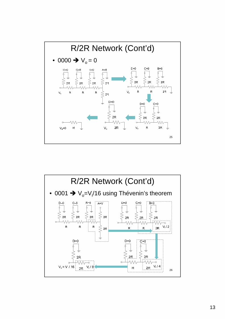
R/2R Network (Cont’d)• 0000 Vo = 0
25
R/2R Network (Cont’d)• 0001 Vo=Vi/16 using Thévenin’s theorem
26
14
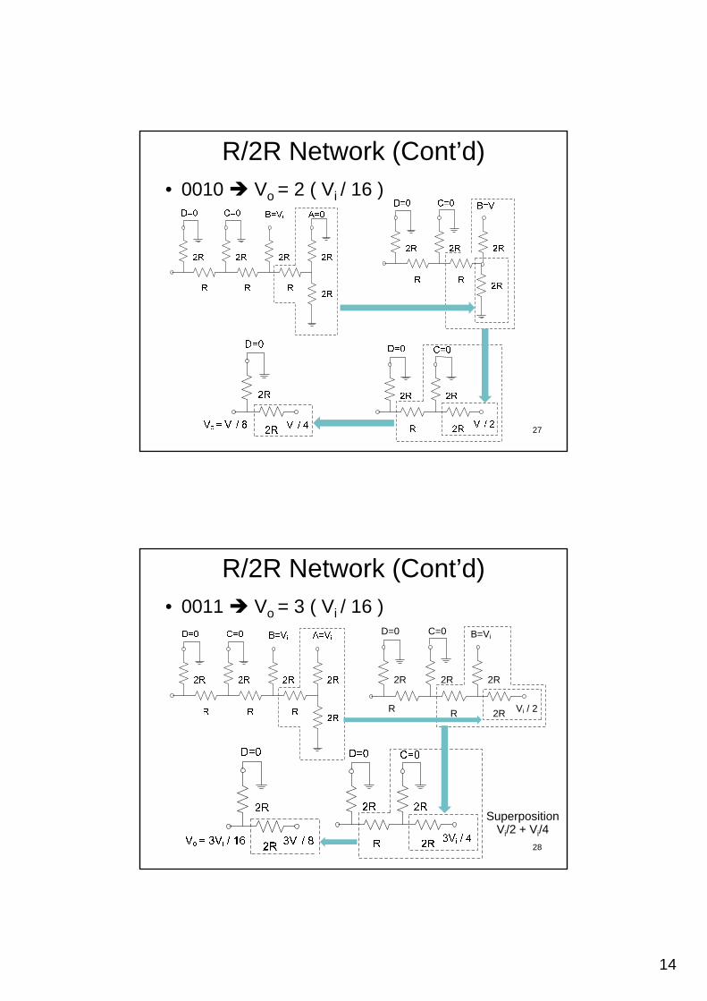
R/2R Network (Cont’d)• 0010 Vo = 2 ( Vi / 16 )
27
R/2R Network (Cont’d)• 0011 Vo = 3 ( Vi / 16 )
C=0D=0 B=Vi
2R 2R 2R
2RRR Vi / 2
28
SuperpositionVi/2 + Vi/4

15
R/2R Network (Cont’d)• The speed of the converter is limited by the
output amplifier slew rate (the maximum t f h f th t t lt )rate of change of the output voltage).
R/2R Ladder
ABCta
l inp
ut
Rf
V–
29
LadderCD Analog output
Dig
it Vo
+ –Rf/R Vo
Inverting Amplifier
Digital Multimeter (DMM)Digital multimeter is an electronic volt-ohm-
milliammeter with digital display.
30

16
Digital Voltmeter
Digital voltmeter (DVM) is essentially an l t di it l t (A/D) ithanalog to digital converter (A/D) with a
digital display.
31
Digital Voltmeter (Cont’d)
• Analogue voltage is sampled at some instant of time (sampled and hold) and ( p )converted to digital signals (series of pulses).
• Number of pulses related to the voltage is counted and displayed as digits.
32
AnalogueInput
Analogue-to-DigitalConverter
DigitalSignal
Counter Display
17
Advantages over Analog Meters• The numerical readout reduces the human reading
error, many readers read the same value, and makes no parallax errorp
• Faster reading
• The accuracy is much higher e.g. the best tolerance of analog meters is about 0.5%, while it is about 0.005% for digital meters
• Higher precision (repeatability) and also contain
33
Higher precision (repeatability) and also contain automatic ranging
• No moving part, life will be long
• Digital signal processing is possible e.g. hold, max, min, polarity or peak
Disadvantages• Battery needed for electronic circuits
• Cannot show trend and continuous changing number not easy to be interpretedchanging number not easy to be interpreted (bar graph may be optional added)
• Cannot measure very high frequency signals (not more than Nyquist rate of sampling)
In spite of above mentioned disadvantages, the digital meters are gaining popularity and are most widely used. 34

18
Relating ADC Value to Voltage
• Not every pin on a microcontroller has the ability to do analog to digital conversions. On the Arduino board, these pins have an ‘A’ in front of their label (A0 through A5) to indicate these pins can read analog voltages.
35
Relating ADC Value to Voltage (Cont’d)
• The ADC on the Arduino is a 10-bit ADC meaning it has the ability to detect 210 or 1,024 discrete analog levels (0-1,023).
36
19
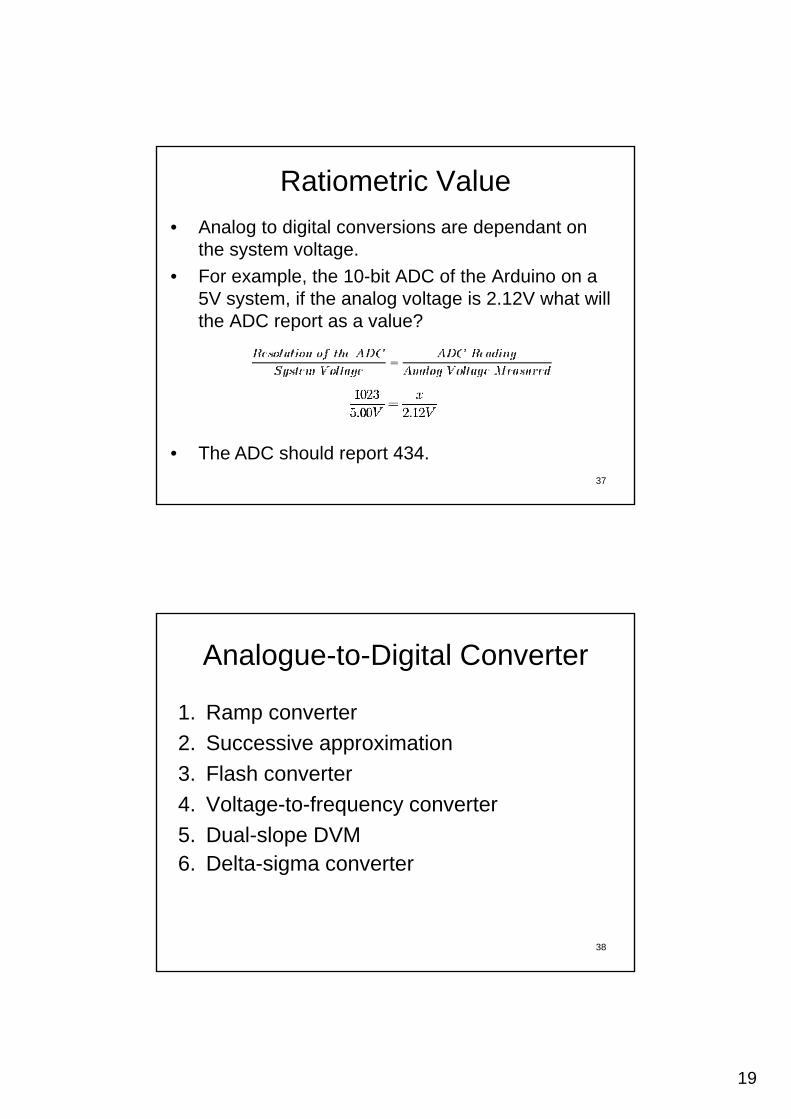
Ratiometric Value
• Analog to digital conversions are dependant on the system voltage.
• For example, the 10-bit ADC of the Arduino on a 5V system, if the analog voltage is 2.12V what will the ADC report as a value?
37
• The ADC should report 434.
Analogue-to-Digital Converter
1. Ramp converter
2. Successive approximation
3. Flash converter
4. Voltage-to-frequency converter
5. Dual-slope DVM
38
6. Delta-sigma converter
20
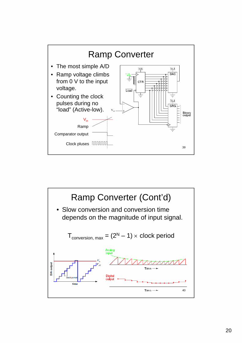
Ramp Converter• The most simple A/D
• Ramp voltage climbs from 0 V to the inputfrom 0 V to the input voltage.
• Counting the clock pulses during no “load” (Active-low).
V
39Clock pluses
Comparator output
Ramp
Vin
Ramp Converter (Cont’d)• Slow conversion and conversion time
depends on the magnitude of input signal.
Tconversion, max = (2N – 1) clock period
40

21
Successive Approximation
Ramp converter Vs. Successive approximation
41
Successive Approximation (Cont’d)
• Input voltage is compared to thecompared to the voltage increased until it reaches the input voltage.
• Trying all values starting with MSB to
42
starting with MSB to LSB.

22
Successive Approximation (Cont’d)D (MSB) C B A (LSB) Vref
0 0 0 0 0
0 0 0 1 1
0 0 1 0 2
e.g. Vin = 9 V
• Vref1 = 8 V (1000)if V > V D = “1”
0 0 1 1 3
0 1 0 0 4
0 1 0 1 5
0 1 1 0 6
0 1 1 1 7
1 0 0 0 8
1 0 0 1 9
if Vin > Vref1 D = 1
• Vref2 = 12 V (1100)if Vin < Vref2 C = “0”
• Vref3 = 10 V (1010)if Vin < Vref3 B = “0”
V 9 V (1001)1 0 1 0 10
1 0 1 1 11
1 1 0 0 12
1 1 0 1 13
1 1 1 0 14
1 1 1 1 1543
• Vref4 = 9 V (1001)if Vin = Vref4 A = “1”Vin = 1001
Successive Approximation (Cont’d)Ex To determine a number between 0-511
(9-bit binary), given the number to be determined is 301.dete ed s 30
44

23
Successive Approximation (Cont’d)• The most common A/D for general applications
• Conversion time is fixed (not depend on the signal magnitude) and relatively fastsignal magnitude) and relatively fast.
Tconversion = N clock period
45
Successive Approximation (Cont’d)
• When you require higher resolution and do not require high sampling rateand do not require high sampling rate
46

24
Flash Converter
• Simultaneous comparison between thecomparison between the analogue input and the reference signals.
• N-bit conversion needs 2N-1 comparators.
• Consumes power (many
47
• Consumes power (many op-amps)
• Fast! up to 20 G Samples / second
Flash Converter (Cont’d)
• Implementation of a priority encodera priority encoder can be simple circuitry.
• 8-line to 3-line priority encoder, e ge.g.00000001 00100000011 01000000111 011
48
25
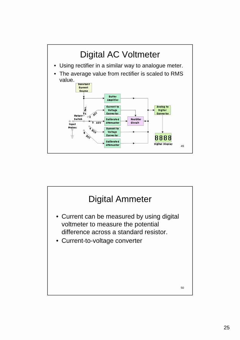
Digital AC Voltmeter• Using rectifier in a similar way to analogue meter.
• The average value from rectifier is scaled to RMS valuevalue.
49
Digital Ammeter
• Current can be measured by using digital lt t t th t ti lvoltmeter to measure the potential
difference across a standard resistor.• Current-to-voltage converter
50

26
Digital Ohmmeter• The DMM supplies a constant current source
to the resistor and the meter measures the voltage across it, the voltage being proportional to the resistance.
51
Reading Resolution
• For the fixed resolution of .001 V (step size)R 0 1 V 3 di it ( 999) 1 000 tRange 0 - 1 V 3 digits ( .999) 1,000 stepsRange 0 - 10 V 4 digits ( 9.999) 10,000 stepsRange 0 - 100 V 5 digits (99.999) 100,000 steps
Number of digit = log(step)
• How many digit for the range 0 - 3 V ?It is 3½ digits ( log(3000) 3.477 digits )
52
27
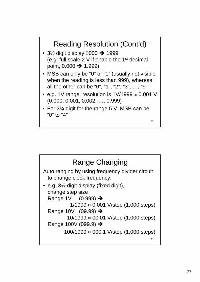
Reading Resolution (Cont’d)• 3½ digit display 0000 1999
(e.g. full scale 2 V if enable the 1st decimal point 0 000 1 999)point, 0.000 1.999)
• MSB can only be “0” or “1” (usually not visible when the reading is less than 999), whereas all the other can be “0”, “1”, “2”, “3”, …, “9”
• e.g. 1V range, resolution is 1V/1999 0.001 V
53
g g(0.000, 0.001, 0.002, …, 0.999)
• For 3¾ digit for the range 5 V, MSB can be “0” to “4”
Range ChangingAuto ranging by using frequency divider circuit
to change clock frequency.
e g 3½ digit display (fixed digit)• e.g. 3½ digit display (fixed digit), change step sizeRange 1V (0.999)
1/1999 0.001 V/step (1,000 steps)Range 10V (09.99)
54
10/1999 00.01 V/step (1,000 steps) Range 100V (099.9)
100/1999 000.1 V/step (1,000 steps)
28
Accuracy
• ( 0.5% Reading + 1 Digit LSB )
• e.g. when you read a voltage 1.8 V
error = (0.5% of 1.8V + 0.001V)
= 0.01V
0.56% of reading
55
Reference
• https://learn.sparkfun.com/tutorials/analog-t di it l ito-digital-conversion
• http://en-us.fluke.com/training/training-library/test-tools/digital-multimeters/digital-multimeter-fundamentals.html
• https://www electrical4u com/digital-• https://www.electrical4u.com/digital-multimeter/
• How to Control LCD Displays - ArduinoTutorial: https://youtu.be/85LvW1QDLLw
56