en_4j2_6c
TRANSCRIPT

SECTION : 6C
POWER STEERING GEARCAUTION : Disconnect the negative battery cable before removing or installing any electrical unit or when a toolor equipment could easily come in contact with exposed electrical terminals. Disconnecting this cable will helpprevent personal injury and damage to the vehicle. The ignition must also be in LOCK unless otherwise noted.
TABLE OF CONTENTSSPECIFICATIONS 6C–1. . . . . . . . . . . . . . . . . . . . . . . . . .
General Specifications 6C–1. . . . . . . . . . . . . . . . . . . . .
Fastener Tightening Specifications 6C–2. . . . . . . . . . .
SPECIAL TOOLS 6C–2. . . . . . . . . . . . . . . . . . . . . . . . . . .
Special Tools Table 6C–2. . . . . . . . . . . . . . . . . . . . . . . .
DIAGNOSIS 6C–3. . . . . . . . . . . . . . . . . . . . . . . . . . . . . . . .
Power Rack and Pinion Steering Gear 6C–3. . . . . . . .
Power Rack and Pinion Steering Gear Bench Testing 6C–5. . . . . . . . . . . . . . . . . . . . . . . . . . . . . . . . .
Speed Sensitive Power Steering System 6C–6. . . . . .
Speed Sensitive Power Steering System OperatingWith Full Assist At All Times 6C–7. . . . . . . . . . . . . . .
Speed Sensitive Power Steering System Operatingwith Decreased Assist At All Times 6C–9. . . . . . . . .
MAINTENANCE AND REPAIR 6C–11. . . . . . . . . . . . . .
ON–VEHICLE SERVICE 6C–11. . . . . . . . . . . . . . . . . . . .
Rack and Pinion Assembly 6C–11. . . . . . . . . . . . . . . . .
Outer Tie Rod 6C–14. . . . . . . . . . . . . . . . . . . . . . . . . . . .
Dust Boot 6C–15. . . . . . . . . . . . . . . . . . . . . . . . . . . . . . . .
Straight–Ahead Check 6C–16. . . . . . . . . . . . . . . . . . . .
Intermediate Shaft and Dash Seal 6C–17. . . . . . . . . .
Hydraulic Cylinder Lines 6C–20. . . . . . . . . . . . . . . . . . .
Speed Sensitive Power Steering Control Module 6C–21. . . . . . . . . . . . . . . . . . . . . . . . . . . . . . . .
UNIT REPAIR 6C–22. . . . . . . . . . . . . . . . . . . . . . . . . . . . .
Rack and Pinion 6C–22. . . . . . . . . . . . . . . . . . . . . . . . . .
Stub Shaft Seals and Upper and Lower Bearing 6C–26. . . . . . . . . . . . . . . . . . . . . . . . . . . . . . . .
Rack Bearing 6C–29. . . . . . . . . . . . . . . . . . . . . . . . . . . .
Rack Bearing Preload Adjustment 6C–30. . . . . . . . . . .
Valve and Pinion 6C–30. . . . . . . . . . . . . . . . . . . . . . . . . .
GENERAL DESCRIPTION AND SYSTEMOPERATION 6C–33. . . . . . . . . . . . . . . . . . . . . . . . . . . . .
Power Rack and Pinion 6C–33. . . . . . . . . . . . . . . . . . . .
Speed Sensitive Power Steering System 6C–33. . . . .
SPECIFICATIONS
GENERAL SPECIFICATIONS
Application Description
Capacity 1.1 Liter (1.16 qt)
Lubricant Power Steering Fluid DEXRON®–II or III
6C – 2IPOWER STEERING GEAR
DAEWOO V–121 BL4
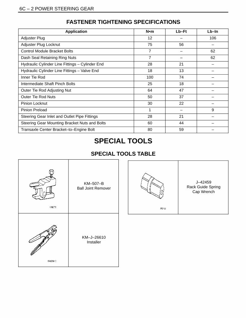
FASTENER TIGHTENING SPECIFICATIONS
Application NSm Lb–Ft Lb–In
Adjuster Plug 12 – 106
Adjuster Plug Locknut 75 56 –
Control Module Bracket Bolts 7 – 62
Dash Seal Retaining Ring Nuts 7 – 62
Hydraulic Cylinder Line Fittings – Cylinder End 28 21 –
Hydraulic Cylinder Line Fittings – Valve End 18 13 –
Inner Tie Rod 100 74 –
Intermediate Shaft Pinch Bolts 25 18 –
Outer Tie Rod Adjusting Nut 64 47 –
Outer Tie Rod Nuts 50 37 –
Pinion Locknut 30 22 –
Pinion Preload 1 – 9
Steering Gear Inlet and Outlet Pipe Fittings 28 21 –
Steering Gear Mounting Bracket Nuts and Bolts 60 44 –
Transaxle Center Bracket–to–Engine Bolt 80 59 –
SPECIAL TOOLS
SPECIAL TOOLS TABLE
KM–507–BBall Joint Remover
KM–J–26610Installer
J–42459Rack Guide Spring
Cap Wrench

POWER STEERING GEAR 6C – 3
DAEWOO V–121 BL4
DIAGNOSIS
POWER RACK AND PINION STEERING GEAR
Hissing Noise
Checks Action
Check the intermediate shaft joints for looseness. Tighten the intermediate shaft joints.
Check the power steering hose for contact with other com-ponents.
Be sure the power steering hose is correctly fitted into thehose clips.
Rattling Noise in Steering Gear
Checks Action
Check the power steering hose for contact with the body. Be sure the power steering hose is correctly fitted into thehose clips.
Check the steering gear for insufficient lubrication. Lubricate the steering gear.
Check the steering gear mounting for improper installa-tion.
Tighten the steering gear mounting bracket nuts and bolts.
Check the outer tie rods for improper installation. Tighten the outer tie rod joints. Replace the outer tie rods.
Poor Return of Steering Wheel to Center
Checks Action
Check the steering wheel for contact with the turn signalhousing.
Adjust the turn signal housing.
Check the intermediate shaft joints for binding or loose-ness.
Replace the intermediate shaft.
Check the power steering pump flow control valve forsticking and improper alignment.
Replace the power steering pump.
Check the wheel alignment. Align the wheels.
Check the wheel bearings for wear or damage. Replace the wheel bearings.
Check the intermediate shaft joints for improper installa-tion.
Adjust the intermediate shaft between the steering gearand the steering column.Replace the intermediate shaft.
Check the outer tie rods and the ball joints for binding orlooseness.
Tighten the tie rods and the ball joints. Replace the tie rodsand the ball joints.
Check the steering gear adjustments. Perform a straight–ahead check.
Check the steering column shaft seal for rubbing on theshaft.
Replace the dash seal.
Check the steering shaft bearings for binding. Replace the stub shaft bearings.
Momentary Increase in Effort When Turning the Wheel Quickly
Checks Action
Check the power steering pump for internal leaks. Replace the power steering pump.
Check the hoses for damage or restricted flow. Replace the power steering hoses and/or pipes.
Check the power steering fluid level. Fill the power steering fluid reservoir.
Check the power steering pump flow control valve forsticking and improper operation.
Replace the power steering pump.

6C – 4IPOWER STEERING GEAR
DAEWOO V–121 BL4
Steering Surges or Jerks When Turning with Engine Running
Checks Action
Check the power steering pump for insufficient pressure. Replace the power steering pump.
Check the power steering pump flow control valve forsticking and improper operation.
Replace the power steering pump.
Check the power steering pump serpentine belt for slip-page.
Tighten the power steering serpentine belt.
Check for air contamination in the power steering system. Bleed the power steering system.
Steering Vibrates During Low Speed or Static Steering
Checks Action
Check for air contamination in the power steering system. Bleed the power steering system.
Check the power steering pump serpentine belt for loose-ness.
Tighten the power steering serpentine belt.
Excessive Wheel Kickback or Loose Steering
Checks Action
Check for air contamination in the power steering system. Bleed the power steering system.
Check the wheel bearings for wear or damage. Replace the wheel bearings.
Check the steering gear mounting for improper installa-tion.
Tighten the steering gear mounting bracket nuts and bolts.
Check the intermediate shaft joints for improper installa-tion.
Adjust the intermediate shaft between the steering gearand the steering column.Replace the intermediate shaft.
Check the outer tie rods and ball joints for looseness. Tighten the tie rods and the ball joints. Replace the tie rodsand the ball joints.
Hard Steering or Lack of Assist (Especially During Parking)
Checks Action
Adjust the intermediate shaft between the steering gearand the steering column. Replace the coupling flange.
Adjust the steering coupling flange on the steering gearand the steering column. Replace the coupling flange asneeded.
Check the power steering pump flow control valve forsticking and improper installation.
Replace the power steering pump.
Check the power steering pump for insufficient pressure. Replace the power steering pump.
Check the power steering pump for internal leaks. Replace the power steering pump.
Check for a loose or a worn intermediate shaft. Tighten the intermediate shaft. Replace the intermediateshaft as needed.
Check the power steering pump serpentine belt tension. Tighten the power steering serpentine belt.

POWER STEERING GEAR 6C – 5
DAEWOO V–121 BL4
POWER RACK AND PINIONSTEERING GEAR BENCH TESTING
Removal, Setup and Testing ProcedureNotice : Pressure checks or pressure and flow checksmay also be conducted using this set–up.
1. Disconnect and remove the power steering gear.Refer to ”Rack and Pinion Assembly” in this sec-tion.
2. Place the power steering gear on a bench next tothe vehicle.
3. Disconnect the pressure line at the point where thehose connects to the pipe. Extend this line in orderto reach the power steering gear on the bench.
4. Disconnect the return line from the the power steer-ing fluid reservoir. Extend this line in order to reachthe power steering gear on the bench.
5. Connect the power steering pipes to the powersteering gear.
6. Start the engine and allow it to idle for 10 seconds.7. Check the power steering fluid level. Refer to Sec-
tion 6A, Power Steering System.8. Start the engine and turn the rack and pinion stub
shaft to a full turn in each direction. Hold the shaftagainst each stop for 5 seconds.
9. Inspect for possible leak points. Refer to Section6A, Power Steering System.
Installation Procedure1. Stop the engine.2. Disconnect the power steering pipes from the pow-
er steering gear.3. Remove the extensions and reconnect the pressure
and return lines.4. Install and connect the power steering gear. Refer
to ”Rack and Pinion Assembly” in this section.5. Start the engine and stay idle for 10 seconds.6. Check the power steering fluid level. Refer to Sec-
tion 6A, Power Steering System.

6C – 6IPOWER STEERING GEAR
DAEWOO V–121 BL4
SPEED SENSITIVE POWER STEERING SYSTEM
POWER STEERING GEAR 6C – 7
DAEWOO V–121 BL4
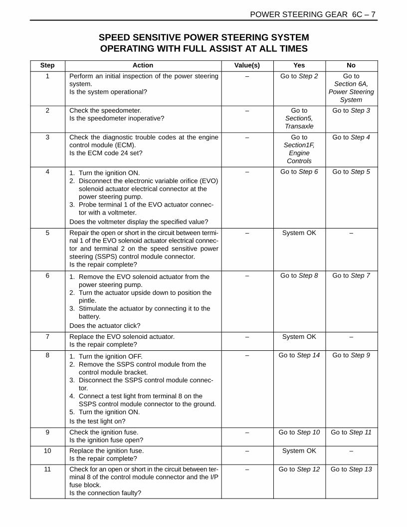
SPEED SENSITIVE POWER STEERING SYSTEMOPERATING WITH FULL ASSIST AT ALL TIMES
Step Action Value(s) Yes No
1 Perform an initial inspection of the power steeringsystem.Is the system operational?
– Go to Step 2 Go toSection 6A,
Power SteeringSystem
2 Check the speedometer.Is the speedometer inoperative?
– Go toSection5,Transaxle
Go to Step 3
3 Check the diagnostic trouble codes at the enginecontrol module (ECM).Is the ECM code 24 set?
– Go toSection1F,
EngineControls
Go to Step 4
4 1. Turn the ignition ON.2. Disconnect the electronic variable orifice (EVO)
solenoid actuator electrical connector at thepower steering pump.
3. Probe terminal 1 of the EVO actuator connec-tor with a voltmeter.
Does the voltmeter display the specified value?
– Go to Step 6 Go to Step 5
5 Repair the open or short in the circuit between termi-nal 1 of the EVO solenoid actuator electrical connec-tor and terminal 2 on the speed sensitive powersteering (SSPS) control module connector.Is the repair complete?
– System OK –
6 1. Remove the EVO solenoid actuator from thepower steering pump.
2. Turn the actuator upside down to position thepintle.
3. Stimulate the actuator by connecting it to thebattery.
Does the actuator click?
– Go to Step 8 Go to Step 7
7 Replace the EVO solenoid actuator.Is the repair complete?
– System OK –
8 1. Turn the ignition OFF.2. Remove the SSPS control module from the
control module bracket.3. Disconnect the SSPS control module connec-
tor.4. Connect a test light from terminal 8 on the
SSPS control module connector to the ground.5. Turn the ignition ON.Is the test light on?
– Go to Step 14 Go to Step 9
9 Check the ignition fuse.Is the ignition fuse open?
– Go to Step 10 Go to Step 11
10 Replace the ignition fuse.Is the repair complete?
– System OK –
11 Check for an open or short in the circuit between ter-minal 8 of the control module connector and the I/Pfuse block.Is the connection faulty?
– Go to Step 12 Go to Step 13

6C – 8IPOWER STEERING GEAR
DAEWOO V–121 BL4
Step NoYesValue(s)Action
12 Repair the open or short in the circuit between termi-nal 8 of the SSPS control module connector and theI/P fuse block.Is the repair complete?
– System OK –
13 Repair the power feed to the ignition fuse F2.Is the repair complete?
– System OK –
14 1. Turn the ignition OFF.2. Connect a test light from terminal 10 of the
SSPS control module connector to B+.Is the test light on?
– Go to Step 16 Go to Step 15
15 Repair the open in the ground circuit between termi-nal 10 of the SSPS control module connector andG203.Is the repair complete?
– System OK –
16 Check for a short to B+ or an open in the circuit be-tween terminal 1 of the SSPS control module con-nector and terminal B of the EVO solenoid actuatorconnector.Is the connection faulty?
– Go to Step 17 Go to Step 18
17 Repair the short to B+ or an open in the circuit be-tween terminal 1 of the SSPS control module con-nector and terminal 2 of the EVO solenoid actuatorconnector.Is the repair complete?
– System OK –
18 1. Disconnect the steering wheel rotation sensor.2. Turn the ignition ON.3. Check for an open, short to ground, short to
B+, or poor terminal contact between terminal5 of the SSPS control module connector andterminal 1 of the steering wheel rotation sensorconnector.
Is the connection faulty?
– Go to Step 19 Go to Step 20
19 Repair the open, short to ground, short to B+, or poorterminal contact between terminal 5 of the SSPScontrol module connector and terminal 1 of thesteering wheel rotation sensor connector.Is the repair complete?
– System OK –
20 Check for an open between terminal 3 of the SSPScontrol module connector and terminal 3 of thesteering wheel rotation sensor connector.Is the connection faulty?
– Go to Step 21 Go to Step 22
21 Repair the open between terminal 3 of the SSPScontrol module connector and terminal 3 of thesteering wheel rotation sensor connector.Is the repair complete?
– System OK –
22 Check for an open, short to ground, short to B+, orpoor terminal contact between terminal 14 of theSSPS control module connector and terminal 2 ofthe steering wheel rotation sensor connector.Is the connection faulty?
– Go to Step 23 Go to Step 24

POWER STEERING GEAR 6C – 9
DAEWOO V–121 BL4
Step NoYesValue(s)Action
23 Repair the open, short to ground, short to B+, or poorterminal contact between terminal 14 of the SSPScontrol module connector and terminal 2 of thesteering wheel rotation sensor connector.Is the repair complete?
– System OK –
24 1. Turn the ignition OFF.2. Connect the SSPS control module.3. Connect the steering wheel rotation sensor.4. Turn the ignition ON.5. Backprobe with a voltmeter from terminal 5 on
the control module connector to the ground.6. Rotate the steering wheel quickly in both direc-
tions.Does the voltage show an increase and decreasefrom the specified value?
� 3 V Go to Step 25 Go to Step 26
25 Replace the SSPS control module.Is the repair complete?
– System OK –
26 Replace the steering wheel rotation sensor.Is the repair complete?
– System OK –
SPEED SENSITIVE POWER STEERING SYSTEMOPERATING WITH DECREASED ASSIST AT ALL TIMES
Step Action Value(s) Yes No
1 Check the speedometer.Is speedometer inoperative?
– Go toSection5,Transaxle
Go to Step 2
2 Disconnect the EVO solenoid actuator at the powersteering pump.Is the symptom still present?
– Go toSection 6A,
Power SteeringSystem
Go to Step 3
3 Replace the speed sensitive poser steering (SSPS)control module.Is repair complete?
– System OK –
General OperationThe control module self–diagnoses SSPS system. If thereis any malfunction, the warning lamp comes ON and at thesame time a trouble code is set. The trouble code can beretrieved or cleared only by SCANTOOL.
In normal condition, If the ignition is turned on, the warninglamp comes on for the first 2 sec and out. During this 2 sec,the control module is diagnosing SSPS system, so a drivercan feel a little heavy steering effort.
If the warning lamp stays on after the 2 sec or comes onafterward, it means there is a malfunction and a relatedtrouble code is recorded.
The warning lamp once come on does not go off even if themalfunction is cleared. It goes off after ignition is turned offand on without a malfunction.
However the trouble code still remains in the control mod-ule.

6C – 10IPOWER STEERING GEAR
DAEWOO V–121 BL4
Trouble Code
DTC Trouble Default Action
01 Actuator circuit open
02 Actuator HI to LO short
03 Actuator circuit short to B+
04 Actuator HI short to Ground Warning lamp ON, Actuator Off
05 Actuator LO short to Ground
06 Steering Wheel Speed Sensor Open
07 Steering Wheel Speed Sensor short to 5V
08 Battey Voltage Out of Range (9~16 V)

POWER STEERING GEAR 6C – 11
DAEWOO V–121 BL4
MAINTENANCE AND REPAIR
ON–VEHICLE SERVICE
RACK AND PINION ASSEMBLY(Left–Hand Drive Shown, Right–Hand DriveSimilar)Tools RequiredKM–507–B Ball Joint Remover
Removal Procedure
1. Disconnect the negative battery cable.2. Raise and suitably support the vehicle.3. Remove the wheels. Refer to Section 2E, Tires and
Wheels.4. Disconnect the power steering gear fluid outlet
pipe. Place a drain pan under the steering gear tocatch the power steering fluid.
5. Disconnect the power steering gear fluid inlet pipe.
6. Position the steering gear straight ahead by turningthe steering wheel until the steering wheel spokesare vertical and pointed to the left.
7. Scribe a mark on the stub shaft housing that linesup with a mark on the intermediate shaft lower cou-pling.
8. Remove the intermediate shaft pinch bolt.

6C – 12IPOWER STEERING GEAR
DAEWOO V–121 BL4
9. Remove the outer tie rod nuts and disconnect thetie rod ends from the strut assembly using the balljoint remover KM–507–B.
10. Remove the crossmember assembly. Refer to Sec-tion 2C, Front Suspension.
11. On vehicles equipped with an automatic transaxle,remove the transaxle center bracket. Refer to Sec-tion 5A, Automatic Transaxle.
12. On vehicles equipped with a manual transaxle, re-move the bolts securing the transaxle center brack-et to the transaxle and the engine. Move the trans-axle center bracket out of the way.
13. Remove the nuts and bolts from the steering gearmounting bracket.
14. Remove the return line from the clip on the cross-member.
15. Disconnect the rack and pinion assembly from thecrossmember assembly.
Installation Procedure
1. Install the rack and pinion assembly on the cross-member. The steering gear must be in a straight–ahead position, and the steering wheel spokesmust be vertical and pointing to the left. Align themarks on the shafts to ensure proper positioning.Seat the stub shaft into the intermediate shaft.

POWER STEERING GEAR 6C – 13
DAEWOO V–121 BL4
2. Install the bolts and nuts on the steering gearmounting bracket.
TightenTighten the steering gear mounting bracket bolts andnuts to 60 NSm (44 lb–ft).
3. Install the return line into the clip on the crossmem-ber.
TightenTightem the return line clip bolt to 8 NSm (71 lb–in).
4. On vehicles equipped with a manual transaxle,position the transaxle center bracket in place andinstall the bolts securing the bracket to the engineand the transaxle.TightenTighten the transaxle center bracket–to–transaxlebolts and the transaxle center bracket–to–engine boltto 80 NSm (59 lb–ft).
5. On vehicles equipped with an automatic transaxle,install the transaxle center bracket. Refer to Section5A, Automatic Transaxle.
6. Install the crossmember. Refer to Section 2C, FrontSuspension.
7. Connect the tie rod ends to the strut assembly.8. Install the outer tie rod nuts.
TightenTighten the outer tie rod nuts to 50 NSm (37 lb–ft).

6C – 14IPOWER STEERING GEAR
DAEWOO V–121 BL4
9. Install the lower intermediate shaft pinch bolt.
TightenTighten the lower intermediate shaft pinch bolt to 25NSm (18 lb–ft).
10. Connect the power steering gear fluid inlet and out-let pipe.
TightenTighten the steering gear inlet and outlet pipe fittingto 28 NSm (21 lb–ft).
11. Perform a front toe adjustment. Refer to Section2B, Wheel Alignment.
12. Install the wheels. Refer to Section 2E, Tires andWheels.
13. Lower the vehicle.14. Do a straight–ahead check. Refer to ”Straight–
Ahead Check” in this section.Notice : When adding fluid or making a complete fluidchange, always use power steering fluid DEXRON®–II orIII or equivalent. Failure to use the proper fluid will causehose and seal damage and fluid leaks.15. Refill the power steering system and check for
leaks. If leaks are found, correct the cause of theleak and bleed the system. Refer to Section 6A,Power Steering System.
16. Connect the negative battery cable.
OUTER TIE RODTools RequiredKM–507–B Ball Joint Remover
Removal Procedure
1. Remove the wheel. Refer to Section 2E, Tires andWheels.
2. Mark the threads on the inner tie rod to aid in re-positioning the adjusting nut.
3. Remove the outer tie rod nut and disconnect theouter tie rod from the steering knuckle using theball joint remover KM–507–B.

POWER STEERING GEAR 6C – 15
DAEWOO V–121 BL4
4. Loosen the outer tie rod adjusting nut and removethe outer tie rod by twisting it off the inner tie rod.
Installation Procedure
1. Reposition the adjusting nut to the marks on theinner tie rod.
2. Install the outer tie rod by twisting it onto the innertie rod.
3. Connect the outer tie rod to the steering knuckle.4. Perform a front toe adjustment. Refer to Section
2B, Wheel Alignment.5. Tighten the adjusting nut.
TightenTighten the outer tie rod adjusting nut to 64 NSm (47lb–ft).
6. Install the outer tie rod nut.
TightenTighten the outer tie rod nut to 50 NSm (37 lb–ft).
7. Install the wheel. Refer to Section 2E, Tires andWheels.
DUST BOOTTools Required
KM–J–22610 Installer
Removal Procedure1. Raise and suitably support the vehicle.2. Remove the wheel. Refer to Section 2E, Tires and
Wheels.3. Remove the outer tie rod. Refer to ”Outer Tie Rod”
in this section.4. Remove the dust boot retaining clamps.5. Remove the dust boot.

6C – 16IPOWER STEERING GEAR
DAEWOO V–121 BL4
Installation Procedure1. Install the dust boot.2. Install the tie rod end dust boot retaining clamp.
Install the cylinder end dust boot retaining clampwith the installer KM–J–22610.
3. Install the outer tie rod. Refer to ”Outer Tie Rod” inthis section.
4. Install the wheel. Refer to Section 2E, Tires andWheels.
5. Lower the vehicle.
STRAIGHT–AHEAD CHECKAfter all the necessary operations on the steering gear arecompleted (removing and installing, disassembling andassembling), check the exact straight–ahead position ofthe steering in each case.
With the vehicle on the floor, place the steering wheel inthe straight–ahead position. Mark the centerline of bothtires on the floor. Turn the steering wheel all the way to theright and mark the new centerline of both tires on the floor.

POWER STEERING GEAR 6C – 17
DAEWOO V–121 BL4
Straight–Ahead Check Table
Step Action Value(s) Yes No
1 Place the steering wheel in the straight–ahead position.Is the wheel in the correct position?
– Go toStep 2
–
2 Is the lower intermediate shaft pinch bolt lyingparallel to the steering gear?
– Go toStep 3
Go toStep 4
3 Is the steering wheel off center by more than5 degrees?
– Go toStep 5
Go toStep 6
4 The pinion is displaced on the rack. The steer-ing pinion position must be corrected.Is the repair complete?
– Go toStep 2
–
5 Remove steering wheel and center on thespindle splines.Is the repair complete?
– Go toStep 3
–
6 Turn the steering wheel all the way to theright. Measure the inner and the outer anglesof the tire centerline compared to the straight–ahead centerline. Are the angles within speci-fications?
Innerangle:37.5°Outer
angle: 31°
SystemOK
Go toStep 7
7 The rack assembly was not assembled cor-rectly.Repair as needed.Is the repair complete?
– Go toStep 6
–
INTERMEDIATE SHAFT AND DASHSEAL
(Left–Hand Drive Shown, Right–HandDrive Similar)
Removal Procedure
1. Turn the steering wheel until it is horizontal, with thespokes pointing down. This is the straight–aheadposition. Make a mark on the stub shaft housingthat lines up with a mark on the intermediate shaftlower universal joint. This mark will be used forproper alignment during installation.
2. Remove the lower pinch bolt from the universal jointon the intermediate shaft.

6C – 18IPOWER STEERING GEAR
DAEWOO V–121 BL4
3. Turn the steering wheel so that the upper pinch boltis accessible. Remove the upper pinch bolt fromthe universal joint on the intermediate shaft.
4. Remove the nuts from the dash seal retaining ringand remove the dash seal retaining ring.
5. Remove the coupling from the power steering gearand pull the intermediate shaft out of the enginecompartment.
Installation Procedure
1. Install the intermediate shaft into the vehicle.
POWER STEERING GEAR 6C – 19
DAEWOO V–121 BL4
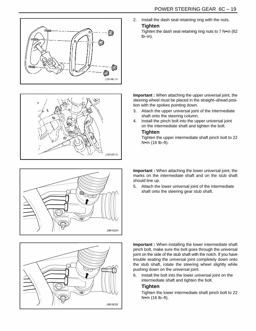
2. Install the dash seal retaining ring with the nuts.
TightenTighten the dash seal retaining ring nuts to 7 NSm (62lb–in).
Important : When attaching the upper universal joint, thesteering wheel must be placed in the straight–ahead posi-tion with the spokes pointing down.3. Attach the upper universal joint of the intermediate
shaft onto the steering column.4. Install the pinch bolt into the upper universal joint
on the intermediate shaft and tighten the bolt.
TightenTighten the upper intermediate shaft pinch bolt to 22NSm (16 lb–ft).
Important : When attaching the lower universal joint, themarks on the intermediate shaft and on the stub shaftshould line up.5. Attach the lower universal joint of the intermediate
shaft onto the steering gear stub shaft.
Important : When installing the lower intermediate shaftpinch bolt, make sure the bolt goes through the universaljoint on the side of the stub shaft with the notch. If you havetrouble seating the universal joint completely down ontothe stub shaft, rotate the steering wheel slightly whilepushing down on the universal joint.6. Install the bolt into the lower universal joint on the
intermediate shaft and tighten the bolt.
TightenTighten the lower intermediate shaft pinch bolt to 22NSm (16 lb–ft).

6C – 20IPOWER STEERING GEAR
DAEWOO V–121 BL4
HYDRAULIC CYLINDER LINES
(Left–Hand Drive Shown, Right–HandDrive Similar)
Removal Procedure
1. Siphon the power steering fluid from the fluid reser-voir.
2. Raise and suitably support the vehicle.3. Disconnect the power steering gear hydraulic cylin-
der pipes from the power steering gear at the valveend. Replace the O–ring seals as needed.
4. Disconnect the power steering gear hydraulic cylin-der pipes from the power steering gear at the cylin-der end.
5. Remove the steering gear hydraulic cylinder pipesfrom the vehicle.
Installation Procedure
1. Lubricate any new O–ring seals with power steeringfluid.
2. Place the O–ring seals into the housing and installthe steering gear hydraulic cylinder pipes.
3. Connect the power steering gear hydraulic cylinderpipes to the power steering gear at the valve end.
TightenTighten the hydraulic cylinder line fittings at the valveend to 18 NSm (13 lb–ft).
4. Connect the power steering gear hydraulic cylinderpipes to the power steering gear at the cylinderend.
TightenTighten the hydraulic cylinder line fittings at the cylin-der end to 28 NSm (21 lb–ft).
5. Lower the vehicle.Notice : When adding fluid or making a complete change,always use DEXRON®–II or III power steering fluid. Fail-ure to use the proper fluid will cause hose and seal dam-age and fluid leaks.

POWER STEERING GEAR 6C – 21
DAEWOO V–121 BL4
6. Fill the fluid reservoir with power steering fluid.7. Inspect for leaks. If there are leaks, correct the
cause of the leaks and bleed the system. Refer to”Bleeding the Power Steering System” in this sec-tion.
SPEED SENSITIVE POWERSTEERING CONTROL MODULE
Removal Procedure1. Disconnect negative battery cable.2. Remove the glove box. Refer to Section 9G, Interi-
or Trim.3. Slide the speed sensitive power steering (SSPS)
control module off from the control module bracket.4. Disconnect the electrical connector from the SSPS
control module.
Installation Procedure1. Connect the electrical connector to the SSPS con-
trol module.2. Slide the SSPS control module onto the SSPS con-
trol module bracket.3. Install the ashtray. Refer to Section 9G, Interior
Trim.4. Connect the negative battery cable.

6C – 22IPOWER STEERING GEAR
DAEWOO V–121 BL4
UNIT REPAIR
RACK AND PINIONTools RequiredKM–J–22610 Installer
Disassembly Procedure
1. Remove the rack and pinion steering assemblyfrom the vehicle. Refer to ”Rack and Pinion Assem-bly” in this section.
2. Remove the valve and pinion assembly from therack and pinion steering assembly. Refer to ”Valveand Pinion” in this section.
3. Remove the rack bearing assembly from the rackand pinion steering assembly. Refer to ”Rack Bear-ing” in this section.
4. Mark the threads on the inner tie rod to aid in re-positioning the adjusting nut.
5. Loosen the adjusting nut and remove the outer tierod nut and the adjusting nut.
6. Remove the dust boot retaining clamps.
7. Remove the dust boot.

POWER STEERING GEAR 6C – 23
DAEWOO V–121 BL4
8. Push back the plastic retainer protecting the con-nection between the inner tie rod and the powersteering gear rack.
9. Counterhold the pinion–side inner tie rod and re-move the cylinder–side inner tie rod.
10. Place a rag over the rack, counterhold the rack as-sembly on the teeth with a wrench, and remove thepinion–side inner tie rod.
Important : The retaining ring can be released by insert-ing a small screwdriver through the hole in the side of thehousing.11. Remove the bulkhead inner cylinder retaining ring
the bulkhead inner cylinder and the rack.
6C – 24IPOWER STEERING GEAR
DAEWOO V–121 BL4
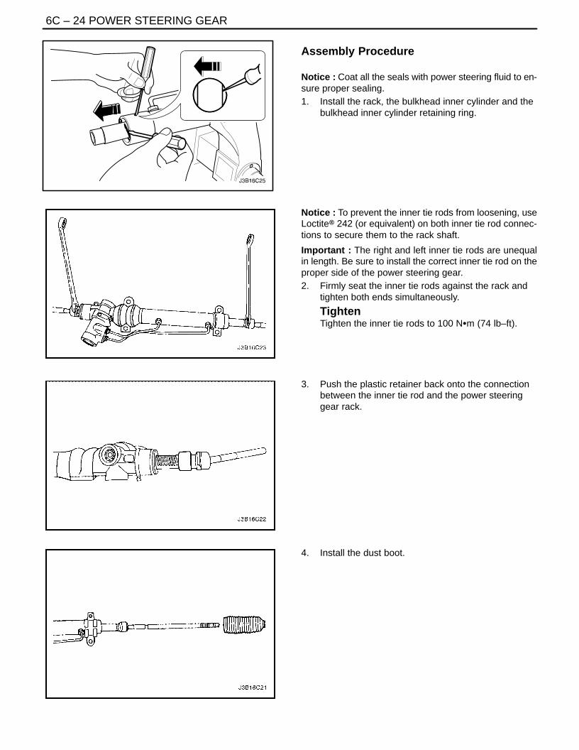
Assembly Procedure
Notice : Coat all the seals with power steering fluid to en-sure proper sealing.1. Install the rack, the bulkhead inner cylinder and the
bulkhead inner cylinder retaining ring.
Notice : To prevent the inner tie rods from loosening, useLoctite® 242 (or equivalent) on both inner tie rod connec-tions to secure them to the rack shaft.
Important : The right and left inner tie rods are unequalin length. Be sure to install the correct inner tie rod on theproper side of the power steering gear.2. Firmly seat the inner tie rods against the rack and
tighten both ends simultaneously.
TightenTighten the inner tie rods to 100 NSm (74 lb–ft).
3. Push the plastic retainer back onto the connectionbetween the inner tie rod and the power steeringgear rack.
4. Install the dust boot.

POWER STEERING GEAR 6C – 25
DAEWOO V–121 BL4
5. Install the cylinder end dust boot retaining clampswith the installer KM–J–22610.
6. Install the tie rod end boot retaining clamps.
7. Reposition the adjusting nut to the marks on theinner tie rod and install the outer tie rod by twistingit onto the inner tie rod.
8. Perform a front toe adjustment. Refer to Section2B, Wheel Alignment.
9. Tighten the adjusting nut.TightenTighten the outer tie rod adjusting nut to 64 NSm (47lb–ft).
10. Install the rack bearing assembly into the rack andpinion steering assembly. Refer to ”Rack Bearing” in this section.
11. Install the valve and pinion assembly into the rackand pinion steering assembly. Refer to ”Valve andPinion” in this section.
12. Install the rack and pinion steering assembly intothe vehicle. Refer to ”Rack and Pinion Assembly” in this section.
6C – 26IPOWER STEERING GEAR
DAEWOO V–121 BL4
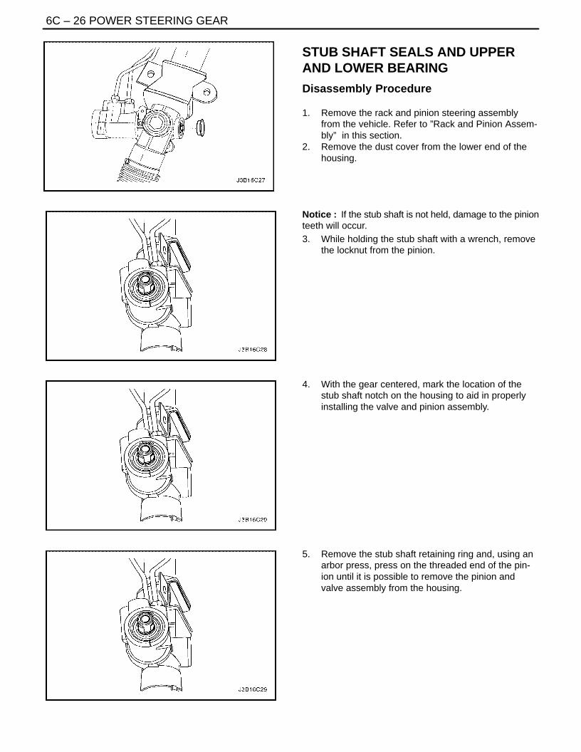
STUB SHAFT SEALS AND UPPERAND LOWER BEARING
Disassembly Procedure
1. Remove the rack and pinion steering assemblyfrom the vehicle. Refer to ”Rack and Pinion Assem-bly” in this section.
2. Remove the dust cover from the lower end of thehousing.
Notice : If the stub shaft is not held, damage to the pinionteeth will occur.3. While holding the stub shaft with a wrench, remove
the locknut from the pinion.
4. With the gear centered, mark the location of thestub shaft notch on the housing to aid in properlyinstalling the valve and pinion assembly.
5. Remove the stub shaft retaining ring and, using anarbor press, press on the threaded end of the pin-ion until it is possible to remove the pinion andvalve assembly from the housing.

POWER STEERING GEAR 6C – 27
DAEWOO V–121 BL4
6. Remove the stub shaft dust seal the stub shaftbearing annulus assembly and the valve assemblyfrom the housing. Discard the stub shaft dust seal.
7. Remove the lower valve assembly bearing and thebushing.
8. Remove the lower bearing assembly retaining ringand press the lower bearing assembly from the low-er end of the housing.
Assembly Procedure
Notice : Coat all the seals with power steering fluid to en-sure proper sealing.1. Install the lower bearing assembly and the lower
bearing assembly retaining ring into the lower endof the housing.

6C – 28IPOWER STEERING GEAR
DAEWOO V–121 BL4
2. Install the lower valve assembly bearing and thebushing.
3. Center the rack in the housing.4. Install the the valve assembly, the stub shaft bear-
ing annulus assembly and a new stub shaft dustseal into the housing.
Important : When the valve and pinion assembly is fullyseated in the housing, be sure that the notch in the stubshaft and the mark on the housing line up.
Notice : If the stub shaft is not held, damage to the pinionteeth will occur.5. While holding the stub shaft, install the locknut onto
the pinion shaft.
TightenTighten the pinion locknut to 30 NSm (22 lb–ft).
6. Replace the dust cover onto the housing.7. Install the rack and pinion steering assembly. Refer
to ”Rack and Pinion Assembly” in this section.

POWER STEERING GEAR 6C – 29
DAEWOO V–121 BL4
RACK BEARINGTools RequiredJ–42459 Rack Guide Spring Cap Wrench
Disassembly Procedure
1. Remove the rack and pinion steering assemblyfrom the vehicle. Refer to ”Rack and Pinion Assem-bly” in this section.
2. Remove the adjuster plug locknut from the adjusterplug, and remove the adjuster plug from the hous-ing with the rack guide spring cap wrench J–42459,or with a 19 mm allen wrench.
3. Remove the adjuster spring and the rack bearing.
Assembly Procedure
1. Coat the rack bearing, the adjuster spring and theadjuster plug with lithium–based grease and installthem into the housing.
2. With the rack centered, turn the adjuster plug clock-wise until a torque of 7 NSm (62 lb–in) is obtained,then back it off by 30 to 40 degrees. Check the pin-ion torque. Maximum pinion preloaded torque is 1NSm (9 lb–in).
3. Thread the locknut on the adjuster plug and tightenit.
TightenTighten the adjuster plug locknut to 75 NSm (56 lb–ft)while holding the adjuster plug stationary with the rackguide spring cap wrench J–42459 or with a 19 mm al-len wrench.
4. Install the rack and pinion assembly. Refer to ”Rackand Pinion Assembly” in this section.
6C – 30IPOWER STEERING GEAR
DAEWOO V–121 BL4
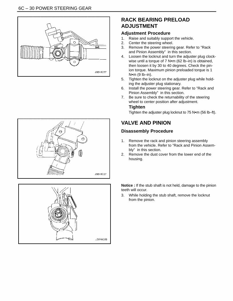
RACK BEARING PRELOADADJUSTMENTAdjustment Procedure1. Raise and suitably support the vehicle.2. Center the steering wheel.3. Remove the power steering gear. Refer to ”Rack
and Pinion Assembly” in this section.4. Loosen the locknut and turn the adjuster plug clock-
wise until a torque of 7 NSm (62 lb–in) is obtained,then loosen it by 30 to 40 degrees. Check the pin-ion torque. Maximum pinion preloaded torque is 1NSm (9 lb–in).
5. Tighten the locknut on the adjuster plug while hold-ing the adjuster plug stationary.
6. Install the power steering gear. Refer to ”Rack andPinion Assembly” in this section.
7. Be sure to check the returnability of the steeringwheel to center position after adjustment.TightenTighten the adjuster plug locknut to 75 NSm (56 lb–ft).
VALVE AND PINION
Disassembly Procedure
1. Remove the rack and pinion steering assemblyfrom the vehicle. Refer to ”Rack and Pinion Assem-bly” in this section.
2. Remove the dust cover from the lower end of thehousing.
Notice : If the stub shaft is not held, damage to the pinionteeth will occur.3. While holding the stub shaft, remove the locknut
from the pinion.

POWER STEERING GEAR 6C – 31
DAEWOO V–121 BL4
4. With the gear centered, mark the location of thestub shaft notch on the housing to aid in properlyinstalling the pinion and valve assembly.
5. Remove the upper housing retaining ring and, usingan arbor press, press on the threaded end of thepinion until it is possible to remove the valve andpinion assembly from the housing.
6. Remove the stub shaft dust seal, the stub shaftbearing annulus assembly and the valve and pinionassembly from the housing.
7. Inspect the valve body rings for wear or damage.Replace the valve body rings as needed. Coat therings with power steering fluid before installation.
8. Remove the lower pinion valve seal and bushing.Discard the seal.

6C – 32IPOWER STEERING GEAR
DAEWOO V–121 BL4
Assembly Procedure
Notice : Coat all of the seals and bushings with powersteering fluid to ensure proper sealing.1. Install the bushing and a new lower pinion valve
seal.
Important : When the valve and pinion assembly is fullyseated in the housing, be sure the notch in the stub shaftand the mark on the housing line up. If this is not done thevehicle will not pass the straight–ahead check and willhave poor steering performance.2. Install the valve and pinion assembly, the stub shaft
bearing annulus assembly and the stub shaft dustseal.
Notice : If the stub shaft is not held, damage to the pinionteeth will occur.3. While holding the stub shaft, tighten the locknut
onto the pinion shaft.
TightenTighten the pinion locknut to 30 NSm (22 lb–ft).
4. Replace the dust cover onto the housing.5. Install the rack and pinion steering assembly. Refer
to ”Rack and Pinion Assembly” in this section.6. Perform the straight–ahead check. Refer to
”Straight–Ahead Check” in this section.

POWER STEERING GEAR 6C – 33
DAEWOO V–121 BL4
GENERAL DESCRIPTIONAND SYSTEM OPERATION
POWER RACK AND PINIONThe power rack and pinion steering system has a rotarycontrol valve that directs hydraulic fluid coming from thehydraulic pump to one side or the other side of the rack pis-ton. The integral rack piston is attached to the rack. Therack piston converts hydraulic pressure to a linear forcethat moves the rack left or right. That force is then trans-mitted through the tie rods to the steering knuckles, whichturn the wheels.
If power rack and pinion steering is not available, manualrack and pinion control is used; however, with this system,more steering effort is required. The movement of thesteering wheel is transferred to the pinion. The rotarymovement of the pinion is then transferred through the pin-ion threads, which mesh with teeth on the rack, therebycausing the rack to move in a linear direction.
A vane–type of hydraulic pump provides hydraulic pres-sure for both steering systems.
SPEED SENSITIVE POWERSTEERING SYSTEMThe speed sensitive power steering (SSPS) system variesthe driver effort required to steer as the vehicle speedchanges. At low speeds, the system provides maximumpower assist for easy turning and parking maneuvers. Athigher speeds, the steering power is reduced to providethe driver with firmer steering and directional stability. TheSSPS system accomplishes this by reducing the amountof power steering fluid flow from the power steering pumpto the power steering gear as the vehicle speed increases.When the vehicle is stationary, the SSPS system providesmaximum fluid flow to the steering gear. As the vehiclespeed increases, the fluid flow to the steering gear is de-creased.
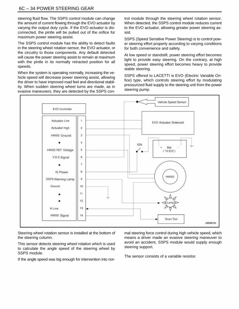
Control ModuleThe SSPS control module processes the vehicle speed in-formation from the engine control module (ECM) and usesthe steering wheel rotation sensor to provide a control sig-nal to the electronic variable orifice (EVO) actuator locatedon the power steering pump.
Electronic Variable Orifice (EVO) ActuatorThe electronic variable orifice (EVO) actuator is located onthe power steering pump and contains a solenoid– oper-ated pintle valve. Fluid leaving the pump passes throughan orifice in the actuator tip. When the EVO actuator ispowered by the SSPS control module, the pintle movesinto the orifice and reduces the power steering fluid flow.
As the vehicle speed increases, current from the SSPScontrol module increases, and the pintle blocks more andmore of the orifice.
Steering Wheel Rotation SensorThe steering wheel rotation sensor is located at the end ofthe steering column housing and is used to send a signalto the controller when abrupt or evasive steering maneu-vers are needed.
Power Steering Pressure HoseSSPS vehicles have a specific pressure hose assemblywhich includes an in–line check valve in the rack and pin-ion assembly. This reduces the amount of steering wheel”kick” when driving over irregular road surfaces while oper-ating at speeds with reduced flow rate and pressure.
Power Rack and PinionExcept for differences in valve machining, the design ofthe SSPS power rack and pinion assembly is the same asfor the a non–SSPS system. The steering wheel move-ment is transferred to the pinion via the intermediate shaft.The pinion moves the rack left or right through meshing thepinion and the rack teeth. The force is then transmittedthrough the tie rods and steering knuckle to steer thewheels.
The power rack and pinion steering system has a rotarycontrol valve which directs the hydraulic fluid from thepower steering pump to one side or the other side of therack piston. The piston is attached to the rack and uses hy-draulic pressure to move the rack left or right. The rotarycontrol valve regulates the degree of assist by respondingto the driver’s torque input.
If hydraulic assist is not available, manual control is main-tained. However, under this condition, more steering effortis required.
Power Steering PumpThe standard vane–type pump, which provides hydraulicpressure for the system, incorporates a special dischargefitting to hold the EVO actuator.
System OperationSystem operation originates with input from the vehiclespeed sensor via the engine control module to the SSPScontrol module. The SSPS control module sends a signalto the SSPS actuator to vary the rate of fluid flow outputby the power steering pump.
Circuit OperationThe SSPS system uses inputs from the speed sensor andsteering wheel rotation sensor to the SSPS controller todetermine the desired amount of power steering assist.
The SSPS control module constantly compares theamount of current flowing through the EVO actuator to thedesired current it has calculated. The EVO actuator has apintle that moves in and out of an orifice, regulating power
6C – 34IPOWER STEERING GEAR
DAEWOO V–121 BL4
steering fluid flow. The SSPS control module can changethe amount of current flowing through the EVO actuator byvarying the output duty cycle. If the EVO actuator is dis-connected, the pintle will be pulled out of the orifice formaximum power steering assist.
The SSPS control module has the ability to detect faultsin the steering wheel rotation sensor, the EVO actuator, orthe circuitry to those components. Any default detectedwill cause the power steering assist to remain at maximumwith the pintle in its normally retracted position for allspeeds.
When the system is operating normally, increasing the ve-hicle speed will decrease power steering assist, allowingthe driver to have improved road feel and directional stabil-ity. When sudden steering wheel turns are made, as inevasive maneuvers, they are detected by the SSPS con-
trol module through the steering wheel rotation sensor.When detected, the SSPS control module reduces currentto the EVO actuator, allowing greater power steering as-sist.
SSPS (Speed Sensitive Power Steering) is to control pow-er steering effort properly according to varying conditionsfor both convenience and safety.
At low speed or standstill, power steering effort becomeslight to provide easy steering. On the contrary, at highspeed, power steering effort becomes heavy to providestable steering.
SSPS offered to LACETTI is EVO (Electric Variable Ori-fice) type, which controls steering effort by modulatingpressurized fluid supply to the steering unit from the powersteering pump.
Steering wheel rotation sensor is installed at the bottom ofthe steering column.
This sensor detects steering wheel rotation which is usedto calculate the angle speed of the steering wheel bySSPS module.
If the angle speed was big enough for intervention into nor-
mal steering force control during high vehicle speed, whichmeans a driver made an evasive steering maneuver toavoid an accident, SSPS module would supply enoughsteering support.
The sensor consists of a variable resistor.

POWER STEERING GEAR 6C – 35
DAEWOO V–121 BL4
1. Steering Wheel2. SSPS control module3. Steering Wheel Rotation Sensor4. Steering Column
Checking procedure is as follows;
1. Remove SSPS connector
2. Turn the ignition ON3. Try to measure 5V across A and C terminals. If you
fail, it might be A, C wiring open or short, or SSPSmodule malfunction.
4. Check if B+ and B– are supplied to terminal �8"and �10" respectively.
TERMINAL VOLTAGE RESISTANCE CONDITION
A�C 4.8 – 5.2 V 9.0 – 10 KW Idle
B�C 0.5 – 4.5 V 0.7 – 12 KW Steering

6C – 36IPOWER STEERING GEAR
DAEWOO V–121 BL4
The flow control actuator is installed on the outlet of theconventional vein type of the power steering pump. Theactuator modulates fluid flow to the steering gear from thepump by current control from the SSPS module.At low speed, small current is supplied to the actuator.Then the actuator modulates flow high and steering effortbecomes light.At high speed, On the contrary, big current to the actuator.Low fluid flow and heavy steering effort.If there happens an actuator malfunction, by default itspintle valve opens the orifice 100% to supply light steeringeffort.The maximum pumping pressure with SSPS option is74.4~81.6 kg/cm2.If you try to measure voltage at the actuator terminal withthe connector removed, you can measure 6.5V.
VEHICLE SPEED (KPH) CURRENT (mA)
0 0
60 50
100 400
140 650
160 700

POWER STEERING GEAR 6C – 37
DAEWOO V–121 BL4
[Vehicle Speed – Actuator Current Relation]
SOLENOID RESISTANCE 13 W
The control module is installed on the right side of the au-dio and can be accessible after the glove box is removed.It receives signals from the vehicle speed sensor and thesteering wheel rotation sensor and processes them to de-cide proper fluid flow through the actuator.It also has a self–diagnosis. If it detects any malfunction,it starts default mode, which is basically actuator full openfor light steering effort.
TERMINAL COLOR FUNCTION
1 SB Actuator Low
2 V Actuator High
3 BW Steering Wheel Sensor Ground
4 – Not used
5 Gr Steering Wheel Sensor 5V ref.
6 GW VSS
7 – Not Used
8 P IGN ON
9 Br Warning Lamp
10 BW Ground
11 – Not Used
12 – Not Used
13 L Diagnosis
14 SB Steering Wheel Sensor Signal