en pxa-h700 - alpine-usa.comvault.alpine-usa.com/products/documents/om pxa-h700.pdf · léalo antes...
TRANSCRIPT

EN
FR
ES
R
ALPINE ELECTRONICS, INC.Tokyo office: 1-1-8 Nishi Gotanda,
Shinagawa-ku, Tokyo 141-8501, JapanTel.: (03) 3494-1101
ALPINE ELECTRONICS OF AMERICA, INC.19145 Gramercy Place, Torrance,
California 90501, U.S.A.Tel.: 1-800-ALPINE-1 (1-800-257-4631)
ALPINE ELECTRONICS OF CANADA, INC.7300 Warden Ave., Suite 203, Markham,
Ontario L3R 9Z6, CanadaTel.: 1-800-ALPINE-1 (1-800-257-4631)
ALPINE ELECTRONICS FRANCE S.A.R.L.(RCS PONTOISE B 338 101 280)
98, Rue de la Belle Etoile, Z.I. ParisNord II, B.P. 50016, 95945, RoissyCharles de Gaulle Cedex, France
Tel.: 01-48 63 89 89
ALPINE ELECTRONICS OF U.K., LTD.13 Tanners Drive, Blakelands,Milton Keynes MK14 5BU, U.K.
Tel.: 01908-61 15 56
ALPINE ELECTRONICS DE ESPAÑA, S.A.Portal de Gamarra 36, Pabellón, 3201013 Vitoria (Alava) - APDO 133,
SpainTel.: 945-283588
ALPINE ELECTRONICS OF AUSTRALIA PTY. LTD.6-8 Fiveways Boulevarde Keysborough,
Victoria 3173, AustraliaTel.: (03) 9769-0000
ALPINE ELECTRONICS GmbHKreuzerkamp 7, 40878 Ratingen,
GermanyTel.: 02102-45 50
ALPINE ITALIA S.p.A.Viale C. Colombo 8,
20090 Trezzano Sul Naviglio (MI), ItalyTel.: 02-48 47 81
PXA-H700
Designed by ALPINE JapanPrinted in Korea (S)
68P02294K30-A
• OWNER'S MANUALPlease read before using this equipment.
• MODE D'EMPLOIVeuillez lire avant d’utiliser cet appareil.
• MANUAL DE OPERACIÓNLéalo antes de utilizar este equipo.
MULTIMEDIA MANAGER™
Kukje Printing Co., Ltd127-2 Gamjeon-dongSasang-guBusan Korea
®


1-EN
FR
ES
DE
SE
IT
ContentsOperating Instructions
WARNING
WARNING .................................................. 2
CAUTION ................................................... 2
PRECAUTIONS ......................................... 3
Basic OperationTurning the power on and off .......................................... 4
About indicators .............................................................. 4Operating the Rotary encoder .......................................... 4Setting the speakers ......................................................... 4Using with Ai-NET connections ..................................... 5
Using with RCA-type or optical cable connections(non Ai-NET connections) ........................................ 5
Automatic AdjustmentsPerforming time correction automatically
(Automated Time Correction) ................................... 6
Settings/AdjustmentsPerforming time correction manually (TCR)/Switching
the phase .................................................................... 8Bass Focus ..................................................................... 10Graphic equalizer adjustments ...................................... 12
Parametric equalizer adjustments ................................. 13X-OVER ........................................................................ 15X-OVER adjustment ..................................................... 16MX settings ................................................................... 18
BASS COMP. setting .................................................... 19
ENGLISHUsing Dolby SurroundUsing the Pro Logic II mode ......................................... 20Adjustment procedure for Dolby Surround ................... 21
Speaker setup ................................................................. 22Adjusting the speaker levels .......................................... 22Mixing bass sound to the rear channel .......................... 23Adjusting the acoustic image......................................... 24
Achieving powerful high volume sound ....................... 25Adjusting the DVD level ............................................... 25
Convenient FunctionsNavigation system voice guidance interruption ............ 26Linear PCM setting ....................................................... 26
Display settings ............................................................. 27MX mode setting (Ai-NET connection) ........................ 27Storing settings in the memory ...................................... 28Calling out stored values ............................................... 28
Defeat mode................................................................... 28Switching the display mode .......................................... 29Switching the color of the illumination ......................... 29
Installation and ConnectionsWarning ......................................................................... 30
Caution .......................................................................... 30Precautions .................................................................... 31Accessories .................................................................... 32Installation ..................................................................... 33Basic Connections Diagram .......................................... 36
Examples of system expansion ...................................... 37
InformationTerminology .................................................................. 41
OthersIn case of difficulty ........................................................ 42Specifications ................................................................ 43
LIMITED WARRANTY

2-EN
WARNINGWARNING
This symbol means important instructions.Failure to heed them can result in serious injuryor death.
DO NOT OPERATE ANY FUNCTION THAT TAKESYOUR ATTENTION AWAY FROM SAFELY DRIVINGYOUR VEHICLE.
Any function that requires your prolonged attentionshould only be performed after coming to a complete stop.Always stop the vehicle in a safe location beforeperforming these functions. Failure to do so may result inan accident.
KEEP THE VOLUME AT A LEVEL WHERE YOU CANSTILL HEAR OUTSIDE NOISE WHILE DRIVING.
Failure to do so may result in an accident.
MINIMIZE DISPLAY VIEWING WHILE DRIVING.
Viewing the display may distract the driver from lookingahead of the vehicle and cause an accident.
DO NOT DISASSEMBLE OR ALTER.
Doing so may result in an accident, fire or electric shock.
USE THIS PRODUCT FOR MOBILE 12VAPPLICATIONS.
Use for other than its designed application may result infire, electric shock or other injury.
KEEP SMALL OBJECTS SUCH AS BATTERIES OUTOF THE REACH OF CHILDREN.
Swallowing them may result in serious injury. Ifswallowed, consult a physician immediately.
USE THE CORRECT AMPERE RATING WHENREPLACING FUSES.
Failure to do so may result in fire or electric shock.
USE ONLY IN CARS WITH A 12 VOLT NEGATIVEGROUND.
(Check with your dealer if you are not sure.) Failure to doso may result in fire, etc.
DO NOT BLOCK VENTS OR RADIATOR PANELS.
Doing so may cause heat to build up inside and may resultin fire.
CAUTIONThis symbol means important instructions.Failure to heed them can result in injury ormaterial property damage.
HALT USE IMMEDIATELY IF A PROBLEM APPEARS.
Failure to do so may cause personal injury or damage tothe product. Return it to your authorized Alpine dealer orthe nearest Alpine Service Center for repairing.

3-EN
FR
ES
DE
SE
IT
PRECAUTIONSTemperature
Be sure the temperature inside the vehicle is between+60°C (+140°F) and –10°C (+14°F) before turning yourunit on.
Installation Location
Make sure the PXA-H700 will not be installed in alocation subjected to:• Direct sun and heat• High humidity and water• Excessive dust• Excessive vibrations
Maintenance
If you have problems, do not attempt to repair the unityourself. Return it to your Alpine dealer or the nearestAlpine Service Station for servicing.
4-EN
About indicators
• PRO LOGIC II indicatorLights green in the Dolby Surround decodemode
• Dolby Digital indicatorLights green in the Dolby Digital decode mode
• DTS indicatorLights green in the DTS decode mode
Operating the Rotary encoder
This unit uses the Rotary encoder whenestablishing settings or adjustments. Whenoperating with the Rotary encoder, press theRotary encoder and startup the Rotary encoderbefore the operation.
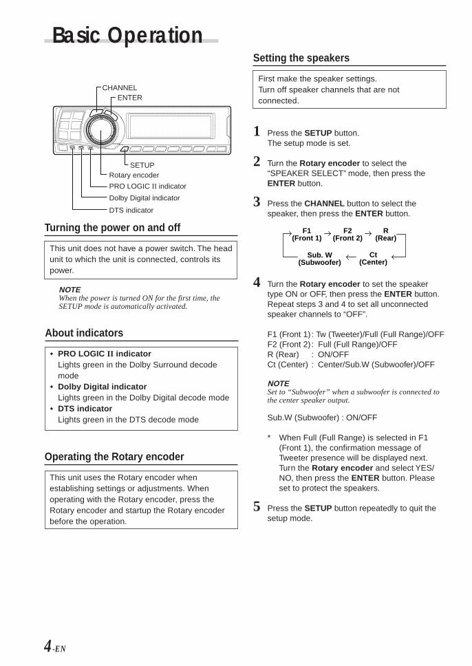
Setting the speakers
First make the speaker settings.Turn off speaker channels that are notconnected.
1 Press the SETUP button.The setup mode is set.
2 Turn the Rotary encoder to select the“SPEAKER SELECT” mode, then press theENTER button.
3 Press the CHANNEL button to select thespeaker, then press the ENTER button.
4 Turn the Rotary encoder to set the speakertype ON or OFF, then press the ENTER button.Repeat steps 3 and 4 to set all unconnectedspeaker channels to “OFF”.
F1 (Front 1) : Tw (Tweeter)/Full (Full Range)/OFFF2 (Front 2) : Full (Full Range)/OFFR (Rear) : ON/OFFCt (Center) : Center/Sub.W (Subwoofer)/OFF
NOTESet to “Subwoofer” when a subwoofer is connected tothe center speaker output.
Sub.W (Subwoofer) : ON/OFF
* When Full (Full Range) is selected in F1(Front 1), the confirmation message ofTweeter presence will be displayed next.Turn the Rotary encoder and select YES/NO, then press the ENTER button. Pleaseset to protect the speakers.
5 Press the SETUP button repeatedly to quit thesetup mode.
Basic Operation
CHANNELENTER
SETUPRotary encoder
Turning the power on and off
This unit does not have a power switch. The headunit to which the unit is connected, controls itspower.
NOTEWhen the power is turned ON for the first time, theSETUP mode is automatically activated.
PRO LOGIC II indicator
Dolby Digital indicator
DTS indicator
Ct(Center)
Sub. W(Subwoofer)
F1(Front 1)
F2(Front 2)
R(Rear)

5-EN
EN
FR
ES
DE
SE
IT
Adjusting the input level
Using the analog, RCA-type connections, thePXA-H700’s input level must be preset from thehead unit.Adjust the input level using a sound source witha high recording level (such as pop or rockmusic).
1 Turn on the head unit’s power.
2 Turn the Rotary encoder on the main unitcounterclockwise and set the volume level to “0”.
3 Gradually increase the volume of the head unituntil “INPUT LEVEL OVER” appears in thedisplay.Reduce the volume slightly from this position,until “INPUT LEVEL OVER” display just turns off.This completes the setting.Do not change the head unit volume level fromthis optimum setting. Use the PXA-H700, only,for changing the volume level.
NOTESwitch to the spectrum analyzer display mode or theinput channel display mode before adjusting the inputlevel. (See page 29)
Adjusting the volume, balance, fader and subwoofer
After determining the input level, adjust thevolume, balance, fader and subwoofer from thePXA-H700. Be careful not to make theseadjustments on the head unit.
1 Press the ENTER button and select the mode tobe adjusted.
2 Turn the Rotary encoder within 5 seconds andadjust to the desired level.
VOLUME : 0 ~ 35BALANCE : L15 ~ R15FADER : F15 ~ R15Sub.W LEVEL : 0 ~ +15
NOTEWhen the subwoofer is set to “OFF”, the Sub.WLEVEL adjustment is ineffective.
Using with RCA-type or optical cableconnections (non Ai-NET connections)
Switching the input
The PXA-H700 is equipped with three sets ofanalog signal inputs and three sets of digitalsignal inputs. For further information aboutconnections, see Page 36.
1 Press the SETUP button.The setup mode is set.
2 Turn the Rotary encoder to select the “INPUTSELECT” mode, then press the ENTER button.
3 Turn the Rotary encoder to select the inputmode, then press the ENTER button.
4 Press the SETUP button repeatedly to quit thesetup mode.
NOTENon Ai-NET connectionsAlpine products are equipped for a bus connectionsystem called “Ai-NET” which can only be used forconnections between Ai-NET products.The PXA-H700 is an Ai-NET product, but is designed toallow connections to other (non Ai-NET) products aswell. Thus RCA-type and optical cable connections arealso possible.Connections to non Ai-NET products are referred to as“non Ai-NET connections”.
Analog 1 Analog 2 Analog 3
Digital 3 Digital 2 Digital 1
VOLUME FADERBALANCE
Sub.W LEVEL
Using with Ai-NET connectionsWhen Ai-NET connections are used, the volume,subwoofer, balance and fader are adjusted fromthe head unit (they cannot be adjusted from thePXA-H700). However, BASS and TREB can notbe adjusted from the head unit, so adjust themfrom PXA-H700.

6-EN
2) Connect the microphone to the PXA-H700.
4 Set the vehicle’s engine key to the ACC position.• Vibrations could make it difficult to achieve
the appropriate adjustment values, so turnthe engine off.
• Noise could make it impossible for automaticmeasurements to be made, so make surethe air conditioner, heater and all otherdevices are turned off.
5 Press the AUTO TCR button.
6 Turn the Rotary encoder , select the tweetersetting, then press the ENTER button.
YES NO
The count down starts.
7 Once the count down starts, get out of thevehicle and shut the doors within 10 seconds.
With the automatic adjustment function, theoperation described below is performed.Adjustments are completed in about 10 seconds.
Time correction. “END” is displayed for about 15 seconds and theautomatic adjustment is completed.
To microphoneinput jack
Microphone
Belt, etc.
To microphoneinput jack
Microphone
AUT TCRO
10 sec .t o s t a r t
Performing time correction automatically(Automated Time Correction)
Due to the particular conditions inside thevehicle, there is a major difference between thedistances of the various speakers and thelistening position. This function uses theincluded measurement microphone toautomatically measure and analyze the distancesbetween the speakers and the listening positionand perform the optimum time correction.
1 Check that the defeat mode is off.(See page 28.)
2 Prepare the vehicle.1) Park the vehicle in a quiet place.2) Close the vehicle’s doors and windows.
3 Connect the microphone.1) Fasten the included microphone at the
center of the driver’s seat’s headrest facingupwards.
Automatic Adjustments
AUTO TCRENTER
Rotary encoder
Base unit

7-EN
EN
FR
ES
DE
SE
IT
• If the microphone does not pick up thesound or the speakers are not working or areconnected or wired improperly, the automaticadjustments are not performed and a errormessage is displayed.Check the various speakers then performthe automatic adjustments again.
8 Check that the automatic adjustment has beencompleted (that “END” has been displayed forabout 15 seconds), then get back into thevehicle and disconnect the microphone.
9 To store, follow the procedure described at“Storing settings in the memory” (page 28).
NOTES• Automatic measurements cannot be made unless the
microphone is connected (error display). To performtime correction automatically, be sure to connect theincluded microphone first.
• Before making automatic measurements, press theAUTO TCR button to cancel it.
• No other operations can be performed whilemeasurements are being made.
• Measurements will differ according to the position inwhich the microphone is mounted.
• Note that using for extended periods of time withoutturning on the engine may wear down the battery.
• Automatic measurements cannot be made for thesubwoofer. Make the subwoofer setting manually.Refer to “Performing time correction manually(TCR)/Switching the phase” (page 8).
• When the speaker is set to the “OFF” mode, the TCRfor that speaker cannot be adjusted. Refer to “Settingthe speakers” (page 4).
• After making the settings, we recommend storingthem in the memory. For instructions, see page 28.
AUT TCRO
ERROR

8-EN
Performing time correction manually(TCR)/Switching the phase
Because of the particular conditions inside thevehicle, there are major differences in thedistances between the different speakers and thelistening position. The proper time correction canbe obtained using the automatic time correctionfunction (“AUTO TCR”), but it is also possible tocalculate the optimum correction values andeliminate the time error at the listening positionyourself using this function. You can also use thisfunction to switch the phase.
1 Check that the defeat mode is off.(See page 28.)
2 Sit in the listening position (the driver’s seat, forexample) and measure the distance (in meters)between your head and the various speakers.
3 Calculate the difference in distance between thefarthest speaker and the other speakers.L = (distance of farthest speaker)
– (distance of other speakers)
4 Divide the distances calculated for the differentspeakers by the speed of sound (343 m/stemperature 20°C).This value is the time correction value for thedifferent speakers.
2.25m
0.5m
5.1ms
• Concrete examples1.Calculating the time correction value for the
front left speaker on the diagram below.
Conditions:Distance between farthest speaker andlistening position: 2.25 m (88-3/4")Distance between front left speaker andlistening position: 0.5 m (20")Calculation: L = 2.25 m (88-3/4") – 0.5 m (20")
= 1.75 m (68-3/4")Compensation time = 1.75 ÷ 343 x 1000
= 5.1 (ms)
In other words, setting the time correction valuefor the front left speaker to 5.1 (ms) sets avirtual distance matching the distance to thefarthest speaker.
The sound is unevenbecause the distancebetween the listeningposition and the differentspeakers is different.The difference in thedistance between thefront left and rear rightspeakers is 1.75 meters(68-3/4").
Time correction eliminatesthe difference betweenthe time required for thesound from the differentspeakers to reach thelistening position.Setting the time correctionof the front left speaker to5.1 ms makes it possibleto coordinate the distancefrom the listening positionto the speaker.
5 Press the TCR/PHASE button to set the timecorrection mode.
Settings/Adjustments
CHANNELENTER
TCR/PHASE
Rotary encoder

9-EN
EN
FR
ES
DE
SE
IT
9 Turn the Rotary encoder to switch the phase,then press the CHANNEL button.Press the ENTER button to return to step 8.
0 180
10 Repeat steps 7 to 9 to adjust other channels.
11 Once the adjustments are completed, press theTCR/PHASE button.
NOTES• When the speaker is set to the “OFF” mode, the TCR
for that speaker is ineffective. Refer to “Setting thespeakers” (page 4).
• After making the settings, we recommend storingthem in the memory. For instructions, see page 28.
(factory default)
6 Press and hold the CHANNEL button for at least2 seconds and select “L and R (LR)” or “L or R”.
L and R (LR): Sets the same adjustment valuesfor the left and right channels.
L or R: Different adjustment values canbe set for the left and rightchannels.
7 Press the CHANNEL button and select thedesired channel, then press the ENTER button.
When “L and R (LR)” is selected:
When “L or R” is selected:
*1 When center is set to subwoofer, it is notdisplayed.
*2 When center is set to subwoofer, it becomesSub.W(L).
*3 When center is set to subwoofer, it becomesSub.W(R).
8 Turn the Rotary encoder to adjust the timecorrection value (0.00 ~ 20.00ms), then pressthe ENTER button.
* The difference in the sound when the defeatmode is turned off (adjusted timecorrection) and on (default value) can bechecked as follows:
1) While in the adjustment mode, press andhold the TCR/PHASE button for at least 2seconds.
2) Press the TCR/PHASE button to switch thedefeat mode on and off and listen to thedifference in the sound.
3) To quit, select the desired setting, then pressthe ENTER button.Note that if you press the ENTER button withthe defeat mode turned on, the adjustmentsare reset to the defeat on status (the defaultvalues).
L and R (LR) L or R
Center
Sub. W
Front 1 Front 2 Rear*1
Front 2 R
CenterSub. W
Front 1 L Front 1 R Front 2 L
Rear R Rear L*2*3
T CR HP A S E FL 1 RR/
DE Y CL A1 0 . m s2
R C5
P HA : 1 8 0 °S E
:
T CR HP A S E FL 1 RR/
DE Y CL A1 0 . m s2
R C5
P HA : 1 8 0 °S E
:

10-EN
Settings/Adjustments
Bass Focus
The time difference between the front-rear/left-right speakers, can be adjusted a pair at a time.Audible time correction can be made from 0.05ms to 20.00 ms in 401 steps (0 to 400).
1 Check that the defeat mode is off.(See page 28.)
2 Press the TCR/PHASE button to select the timecorrection mode.
3 Press the B.C. button to select the “BASSFOCUS” setting mode.
4 Press the CHANNEL button to select the front-rear/left-right speaker.
5 Turn the Rotary encoder to set the step of front-rear/left-right.
6 Moreover, for setting another channel (speaker),repeat steps 4 and 5.
7 After completing the setting, press the ENTERbutton to return to the time correction mode.Here, you can compare the sound of Defeat OFF(adjustment value) and Defeat ON (initial).For the operation method, refer to step 8 of“Performing time correction manually (TCR)/Switching the phase” on page 9.
8 Press the TCR/PHASE button to complete thesetting.
NOTEThe setting made in Bass Focus is reflected in the timecorrection.
FL FR
RL RR
FL FR
RL RR
FL FR
RL RR
FL FR
RL RR
Front (left-right)speakers
Left (front-rear)speakers
Rear (left-right)speakers
Right (front-rear)speakers
CHANNELENTER
TCR/PHASE
B.C.
Rotary encoder

11-EN
EN
FR
ES
DE
SE
IT
Example of Steps 4 and 5 Setting1.After entering corrections for the front (left and
right) speakers in STEP 30, the time differenceis 1.5 ms for both front-left and front-rightspeakers.
2. After entering corrections for the left (front andrear) speakers in STEP 30, the time differencebecomes 3.0 ms* for the front left speaker, and1.5 ms for the left rear speaker.* Because the time difference was already set
to 1.5 ms for the front left speakers in STEP 1,the additional correction in STEP 30 makesthe time difference of the front left speaker 3.0ms.
1.5ms1.5ms
1.5ms
1.5ms
3.0ms
1.5ms1.5ms
Time difference Table
Numberof
steps
0
1
2
3
4
5
6
7
8
9
10
11
12
13
14
15
16
17
18
19
20
21
22
23
24
25
26
27
28
29
30
31
32
33
TimeDifference
(ms)
0.00
0.05
0.10
0.15
0.20
0.25
0.30
0.35
0.40
0.45
0.50
0.55
0.60
0.65
0.70
0.75
0.80
0.85
0.90
0.95
1.00
1.05
1.10
1.15
1.20
1.25
1.30
1.35
1.40
1.45
1.50
1.55
1.60
1.65
Numberof
steps
34
35
36
37
38
39
40
41
42
43
44
45
46
47
48
49
50
51
52
53
54
55
56
57
58
59
60
61
62
63
64
65
66
67
TimeDifference
(ms)
1.70
1.75
1.80
1.85
1.90
1.95
2.00
2.05
2.10
2.15
2.20
2.25
2.30
2.35
2.40
2.45
2.50
2.55
2.60
2.65
2.70
2.75
2.80
2.85
2.90
2.95
3.00
3.05
3.10
3.15
3.20
3.25
3.30
3.35
Numberof
steps
68
69
70
71
72
73
74
75
76
77
78
79
80
81
82
83
84
85
86
87
88
89
90
91
92
93
94
95
96
97
98
99
100–399
400
TimeDifference
(ms)
3.40
3.45
3.50
3.55
3.60
3.65
3.70
3.75
3.80
3.85
3.90
3.95
4.00
4.05
4.10
4.15
4.20
4.25
4.30
4.35
4.40
4.45
4.50
4.55
4.60
4.65
4.70
4.75
4.80
4.85
4.90
4.95
5.00–19.95
20.00

12-EN
Settings/Adjustments
(factory default)
*3 When center is set to subwoofer, it becomesSub.W(R).
5 Turn the Rotary encoder to select thefrequency, then press the ENTER button.
Adjustable frequenciesFront/Rear/Center: 20Hz~20kHz (1/3 octavestep)Sub.W: 20Hz~160Hz (1/3 octave step)
6 Turn the Rotary encoder to adjust the level (± 9dB in steps of 1 dB), then press the ENTERbutton.
7 Repeat steps 5 and 6 to adjust otherfrequencies.
8 To adjust other channels, press the CHANNELbutton to return to step 4.
* The difference in the sound when the defeatmode is turned off (adjusted graphicequalizer settings) and on (default values)can be checked as follows:
1) While in the adjustment mode, press andhold the G.EQ button for at least 2 seconds.
2) Press the G.EQ button to switch the defeatmode on and off and listen to the differencein the sound.
3) To quit, select the desired setting, then pressthe ENTER button.Note that if you press the ENTER button withthe defeat mode turned on, the adjustmentsare reset to the defeat on status (the defaultvalues).
9 Once the adjustments are completed, press theG.EQ button.
NOTES• When the speaker is set to the “OFF” mode, the
graphic equalizer for that speaker is ineffective.Refer to “Setting the speakers” (page 4).
• Check the playable frequency ranges of the connectedspeakers before making the equalizer adjustments. Ifthe speaker’s playable frequency range is 55 Hz to 30kHz, for example, adjusting the 40 Hz or 20 Hz bandhas no effect. Additionally, you may overload anddamage the speakers.
• After making the settings, we recommend storingthem in the memory. For instructions, see page 28.
• When graphic EQ is adjusted, the adjustment forparametric EQ becomes ineffective.
CHANNELENTER
G.EQ
P.EQRotary encoder
Graphic equalizer adjustments
The graphic equalizer allows you to modify thesound using 31 bands each for the front (left andright), rear (left and right) and center speakers.An additional 10 bands are available for thesubwoofer. This allows you to customize thesound to suit your taste.
1 Check that the defeat mode is off.(See page 28.)
2 Press the G.EQ button to set the graphicequalizer mode.
3 Press and hold the CHANNEL button for at least2 seconds and select “L and R (LR)” or “L or R”.
L and R (LR): Sets the same adjustment valuesfor the left and right channels.
L or R: Different adjustment values canbe set for the left and rightchannels.
4 Press the CHANNEL button to select the desiredchannel, then press the ENTER button.
When “L and R (LR)” is selected:
When “L or R” is selected:
*1 When center is set to subwoofer, it is notdisplayed.
*2 When center is set to subwoofer, it becomesSub.W(L).
Front Rear Center Sub. W*1
Rear R
CenterSub. W
Front L Front R Rear L*2*3
3 1 – . E Q F r o n t LG
– 9 d B1 2 . 5 k H z
L and R (LR) L or R

13-EN
EN
FR
ES
DE
SE
IT
6 Turn the Rotary encoder to select thefrequency, then press the ENTER button.For the adjustable frequencies, see page 43.
7 Turn the Rotary encoder to adjust the bandwidth (Q), then press the ENTER button.The band width can be adjusted in 6 steps of0.5/1/2/3/4/5.
8 Turn the Rotary encoder to adjust the level (±9dB in steps of 1 dB), then press the ENTERbutton.
(factory default)
L and R (LR) L or R
Front Rear Center Sub. W*1
Rear R
CenterSub. W
Front L Front R Rear L*2*3
P . E FP r o n t LQ
B A : 4ND3 . 1F c : H z5 k
QL v : + 7 d B
: 2
Parametric equalizer adjustments
The frequency bands of the graphic equalizer arefixed. This makes it very difficult to correct forundesired peaks and dips at specific frequencies.The parametric equalizer’s center frequency canbe tuned these specific frequencies. Then, thebandwidth (Q) and level are fine-tuned,independently, to make the necessarycorrections. The parametric equalizer function isan advanced tool for serious audiophiles.
1 Check that the defeat mode is off.(See page 28.)
2 Press the P.EQ button to set the parametricequalizer mode.
3 Press and hold the CHANNEL button for at least2 seconds and select “L and R (LR)” or “L or R”.
L and R (LR): Sets the same adjustment valuesfor the left and right channels.
L or R: Different adjustment values can beset for the left and right channels.
4 Press the CHANNEL button to select the desiredchannel, then press the ENTER button.
When “L and R (LR)” is selected:
When “L or R” is selected:
*1 When center is set to subwoofer, it is notdisplayed.
*2 When center is set to subwoofer, it becomesSub.W(L).
*3 When center is set to subwoofer, it becomesSub.W(R).
5 Turn the Rotary encoder to select the band,then press the ENTER button.
Adjustable bandsFront/Rear/Center : 5 bandsSub.W : 2 bands
P . E FP r o n t LQ
B A : 4ND3 . 1F c : H z5 k
Q :L v : + 7 d B
2
P . E FP r o n t LQ
B A : 4ND3 . 1F c : H z5 k
QL v : + 7 d B
: 2
P . E F r o n t LQ
B A : 4ND3 . 1F c : H z5 k
QL v : + 7 d B
: 2

14-EN
NOTES• When the speaker is set to the “OFF” mode, the
parametric equalizer for that speaker is ineffective.Refer to “Setting the speakers” (page 4).
• It is not possible to adjust the frequencies of adjacentbands within 7 steps.
• Check the playable frequency ranges of the connectedspeakers before making the equalizer adjustments. Ifthe speaker's playable frequency range is 55 Hz to 30kHz, for example, adjusting the 40 Hz or 20 Hz bandhas no effect. Additionally, you may overload anddamage the speakers.
• After making the settings, we recommend storingthem in the memory. For instructions, see page 28.
• When parametric EQ is adjusted, the adjustment forgraphic EQ becomes ineffective.
Settings/Adjustments
9 Repeat steps 5 to 8 to adjust other bands.
10 To adjust other channels, press the CHANNELbutton to return to step 4.
* To compare the factory default settings(DEFEAT ON) with your newly adjustedparametric equalizer settings (DEFEATOFF), do the following:
1) While in the adjustment mode, press andhold the P.EQ button for at least 2 seconds.
2) Press the P.EQ button to switch the defeatmode on and off and listen to the differencein the sound.
3) To quit, select the desired setting, then pressthe ENTER button.Note that if you press the ENTER button withthe defeat mode turned on, the adjustmentsare reset to the defeat on status (the defaultvalues).
11 Once the adjustments are completed, press theP.EQ button.
CHANNELENTER
P.EQ

15-EN
EN
FR
ES
DE
SE
IT
X-OVER
The PXA-H700 is equipped with an activecrossover allowing the frequency bands to besplit before amplification. Because of this, thereis no need for a passive network between thespeakers and amplifiers. This makes theamplifiers fully independent, eliminating theproblem of interference. This also makes itpossible to achieve the optimum acoustic spaceby dividing the playback frequencies in a waysuited to the speaker’s response.This adjustment requires sufficient knowledgeand experience. If you have problems, wesuggest you have the adjustment made by yourstore authorized of Alpine dealer.
Adjust the high pass filter (H.P.F.) and low passfilter (L.P.F.) and set the slope (filter responseattenuation slope) for the different bands.Make the adjustments according to the playablefrequency ranges and frequency responses ofthe connected speakers.
Cutoff frequency adjustment range (1/6 octave steps)
Slope adjustment
H.P.F. L.P.F. H.P.F. L.P.F.
Front 1(Front speaker 1)Select TWEETER
6/12/18/24/30dB
6/12/18/24/30dB/Filter OFF
1kHz –18kHz
1.1kHz –20kHz
Front 1(Front speaker 1)
Select FULL RANGE
6/12/18/24/30dB/Filter OFF
6/12/18/24/30dB/Filter OFF
20Hz –18kHz
22Hz –20kHz
Front 2(Front speaker 2)
6/12/18/24/30dB/Filter OFF
6/12/18/24/30dB/Filter OFF
20Hz –18kHz
22Hz –20kHz
Rear(Rear speaker)
6/12/18/24/30dB/Filter OFF
6/12/18/24/30dB/Filter OFF
20Hz –18kHz
22Hz –20kHz
Center*(Center speaker)
6/12/18/24/30dB/Filter OFF
6/12/18/24/30dB/Filter OFF
20Hz –18kHz
22Hz –20kHz
Sub. W(Subwoofer)
6/12/18/24/30dB/Filter OFF
6/12/18/24/30dB20Hz –
180Hz22Hz –200Hz
20Hz 10kHz
The H.P.F. setting cannot be the same as orexceed the L.P.F. setting for that channel.
• The crossover network is a filter that dividesspecific frequency bands.
• The high pass filter is a filter that cutsfrequencies below a certain frequency (bassfrequencies) and lets through treblefrequencies.
• The low pass filter is a filter that cutsfrequencies above a certain frequency(treble frequencies) and lets through bassfrequencies.
• The slope is a value expressing theattenuation of the signal in decibels when thefrequency is increased or decreased by oneoctave.
• The higher the slope value, the steeper theslope.
• If the slope is set to “OFF”, the signal doesnot pass through the filter, so there is noeffect.
• In order to protect the speakers, if Tweeter isselected in Front 1, there is no filter OFF(slope OFF) setting for H.P.F.For the same reason, the subwoofer lowpass filter cannot be turned off (the slopecannot be set to “OFF”.)
• Tweeters may be damaged if low frequencysignals are input to them.
Signals with these frequencies output
Slope adjustment
Slope OFF
H.P.F. cutoff frequency L.P.F. cutoff frequency
* If center is set as subwoofer, the adjustmentrange changes to the range of subwoofer.

16-EN
X-OVER adjustment
This section describes the procedure for makingthe X-OVER adjustment. Before performing thisprocedure, see “X-OVER” on page 15.
1 Check that the defeat mode is off.(See page 28.)
2 Press the X-OVER button to set the X-OVERadjustment mode.
3 Press and hold the CHANNEL button for at least2 seconds and select “L and R (LR)” or “L or R”.
L and R (LR): Sets the same adjustment valuesfor the left and right channels.
L or R: Different adjustment values can beset for the left and right channels.
4 Press the CHANNEL button to select the desiredchannel, then press the ENTER button.
When “L and R (LR)” is selected:
When “L or R” is selected:
*1 When center is set to subwoofer, it is notdisplayed.
*2 When center is set to subwoofer, it becomesSub.W(L).
*3 When center is set to subwoofer, it becomesSub.W(R).
Settings/Adjustments
(factory default)
5 Turn the Rotary encoder to adjust the H.P.F.cutoff frequency, then press the ENTER button.The adjustable bands differ according to thechannel (speaker).
6 Turn the Rotary encoder to adjust the H.P.F.slope, then press the ENTER button.To set filter off (slope off), press and hold the X-OVER button for at least 2 seconds.
7 Next, make the adjust for the L.P.F. in the sameway as in steps 5 and 6.
8 Turn the Rotary encoder to adjust the level,then press the CHANNEL button.Press the ENTER button to return to step 5.
The level can be adjusted between –12 and 0.
9 Repeat steps 4 to 8 to adjust other channels.
10 Once the adjustments are completed, press theX-OVER button.
CHANNELENTER
X-OVER
Rotary encoder
L and R (LR) L or R
Center
Sub. W
Front 1 Front 2 Rear*1
Front 2 R
CenterSub. W
Front 1 L Front 1 R Front 2 L
Rear R Rear L*2*3
X – O RP F r o n t 2 1/2V E
HP : 3 5 0f cl o pH P s 1 2e :
L P f 1c :L P s p e : 6I o
. 8 k
X – O RP F r o n t 2V E
HP : 3 5 0f cl o pH P s 1 8e :
L P f 1 . 8 kc :L P s p e : 6I o
1/2
X – O RP F r o n t 2V E
L e l :v e– d B4
2/2

17-EN
EN
FR
ES
DE
SE
IT
Hint for adjusting the subwoofer• If the subwoofer is installed on the rear deck,
setting a gentle L.P.F. slope (for example 6 dB/oct.) makes the sound localization more to therear. This can also affect the acousticlocalization of the front.
Hints for adjusting the high range• Depending on the speaker, inputting low
frequency component signals (about 2 kHz orless) with the H.P.F. adjustment could result indistortion. If so, set a steep slope (for example30 dB/oct.).When doing so, adjust so that the mid and highrange sounds do not separate.
• Normally use with the L.P.F. off. If the highrange is too strong, we recommend adjusting fora gentle slope.
Hint for adjusting the low range• When a subwoofer is connected and you are
using a speaker with a low range of under 10 or12 cm (3-15/16" or 4-3/4"), setting the low rangeH.P.F. to “OFF” can result in distortion when lowfrequency components are input.If so, set the H.P.F. slope to a value suited forthe speaker’s frequency response.
NOTES• In order to protect the speakers, if Tweeter is selected
in Front 1, there is no filter OFF (slope OFF) settingfor H.P.F.For the same reason, the subwoofer low pass filtercannot be turned off (the slope cannot be set to“OFF”.)
• When the speaker is set to the “OFF” mode, the X-OVER for that speaker is ineffective. Refer to“Setting the speakers” (page 4).
• Check the playback frequencies of the connectedspeakers before adjusting.
• After making the settings, we recommend storingthem in the memory. For instructions, see page 28.

18-EN
MX settings
MX (Media Xpander) makes vocals orinstruments sound distinct regardless of themusic source. The radio, CD, and MP3, will beable to reproduce the music clearly even in carswith a lot of road noise.
1 When “Auto” has been set as the MX modesetting (see page 27) while using the PXA-H700 in combination with an Ai-NET headunit equipped with an automatic MX modeselection function (DVA-7996, etc.)In this case, the MX mode is selectedautomatically according to the music source onthe head unit. The MX mode can be set fromthe PXA-H700 using the operation describedbelow.
1 Press the MX button to set the MX setting mode.
2 In case of “MX OFF”, press and hold the MXbutton for at least 2 seconds to turn the MXmode on.
3 Turn the Rotary encoder to select the desiredmode, then press the ENTER button.• When “OFF” is selected, the MX effect is
turned off.• The level for the currently selected music
source (radio, CD, etc.) can be adjusted.
FM: MX1 to 3 and OFFThe medium to high frequencies becomemore clear, and produces well balancedsound in all the bands.
CD: MX1 to 3 and OFFCD mode processes a large quantity of data.This data is used to reproduce the soundcleanly by making use of the data quantity.
MP3/XM: MX1 to 3 and OFFThis corrects information that was omitted atthe time of compression. This reproduces awell-balanced sound close to the original.
DVD/Video CD: MOVIE MX 1~2, MUSIC, OFFMOVIE MX 1~2: The dialogues of moviesare played with greater clarity.MUSIC: Discs containing music clips areplayed with a more dynamic sound.
AUX: MP3, MUSIC, MOVIE, OFFChoose the MX mode (MP3, MUSIC, orMOVIE) that corresponds to the mediaconnected.
4 Once the settings are completed, press the MXbutton.
NOTES• Operations cannot be performed when the defeat
mode (page 28) is on.• Each music source, such as radio, CD, and MP3 can
have its own MX setting.• If "MX OFF" is set in step 2, the MX mode is set to
off for all music sources.
2 When combining non Ai-Net head unitproductsWhen combining Ai-Net head unit productswithout MX interlocking functionWhen combining Ai-Net head unit products(DVA-7996, etc.) with MX interlockingfunction considering that “MX mode setting”(page 27) is set to “Manual”.In these cases, the PXA-H700 is not interlockedwith the head unit, therefore it is necessary to setthe MX from the PXA-H700 with the operationsbelow.
1 Press the MX button to set the MX setting mode.
2 In case of “MX OFF”, press and hold the MXbutton for at least 2 seconds to turn the MXmode on.
Settings/Adjustments
ENTER
MX B.C.
Rotary encoder

19-EN
EN
FR
ES
DE
SE
IT
3 Turn the Rotary encoder to select the source(media) you want to set, then press the ENTERbutton.
4 Turn the Rotary encoder to select the desiredmode, then press the ENTER button.For further information about setting mode, seestep 3 of 1 (page 18).
5 To set other sources (media), press the MXbutton and return to step 3.
6 Once the settings are completed, press the MXbutton repeatedly.
NOTES• Operations cannot be performed when the defeat
mode (page 28) is on.• The source (media), such as radio, CD, and MP3 can
be set.• “MX OFF” can be set in step 2.
BASS COMP. setting
The sound of the low frequencies can beadjusted to suit your tastes.
1 Check that the defeat mode is off.(See page 28.)
2 Press the B.C. button to set the “BASS COMP.”setting mode.
3 In case of “BASS COMP. OFF”, press and holdthe B.C. button for at least 2 seconds to turn theBASS COMP. mode on.
4 Turn the Rotary encoder to select the desiredmode, then press the ENTER button.As the bass level increases in order of BASSCOMP. 1, BASS COMP. 2, BASS COMP. 3, youcan enjoy listening to the powerful sound.
5 Once the settings are completed, press the B.C.button.
NOTE“BASS COMP. OFF” can be set in step 3.

20-EN
* If DOLBY PL II MUSIC is selected, thecenter width can be adjusted with followingoperations.This function offers the optimum vocal positionby adjusting the center channel positionbetween the center speaker and the L/Rspeaker. (The adjustments established in“Adjusting the acoustic image” (page 24) areineffective while this function is activated.)
1) After selecting DOLBY PL II MUSIC, within15 seconds, press and hold the PLII /REAR FILL button for at least 2 seconds.
2) Turn the Rotary encoder to select “CenterWidth ON” or “Center Width OFF”, thenpress the ENTER button.When the setting is turned ON, the optimumvocal position is offered by adjusting thecenter channel position between the centerspeaker and the L/R speaker.
3) Turn the Rotary encoder to adjust the level,then press the ENTER button.The level can be adjusted between 0 to 7.When the level increases, the center channelposition moves from the center speakerposition to both side.
4) After the setting, press and hold the PLII /REAR FILL button for at least 2
seconds.
NOTES• Avoid stopping, pausing, switching the disc, cueing,
fast-forwarding or switching the audio channel of theplayer while making this adjustment. The setting iscanceled if the decode mode is switched.
• This adjustment is ineffective if the center speaker isset to “OFF” or “Sub.W” in the speaker setupsettings.
2 Once the settings are completed, press the DISPbutton.
NOTES• This function only works with two-channel signals.
This operation is ineffective when 5.1-channel DTSor Dolby Digital signals are input.
• “REAR FILL” functionDepending on the input signals, the sound may onlybe output from the front speakers. In this case, the“REAR FILL” function can be used to output signalsfrom the rear speakers as well.
• If the setting of REAR FILL is made when REAR MIXis ON, sound is unchanged in the rear fill settingbecause REAR MIX is given priority during 2channel decoder other than linear PCM.
• For linear PCM signals, the voice is output from therear speaker regardless of the REAR FILL and REARMIX setting.
• Once the settings are made, we recommend storingthem in the memory. See page 28 for instructions.
Using Dolby Surround
PLII/REAR FILL
ENTER
DISP
Using the Pro Logic II mode
With the PXA-H700, Pro Logic processing can beconducted on the music signals recorded on twochannels to achieve Dolby Pro Logic II surroundsound. For two-channel Dolby Digital and DTSsignals, there is also a “REAR FILL” function foroutputting the signals of the front channel to therear channel.
1 Press the PLII /REAR FILL button and selectthe desired mode.The setting mode is canceled if no operation isperformed within 15 seconds after the mode isselected.
DOLBY PL II MOVIE: Suits the stereo TVshows and all programsencoded in DolbySurround. It improvesthe sound fielddirectivity to near that ofdiscrete 5.1-channelsound.
DOLBY PL II MUSIC: Can be used for allstereo musicrecordings, andprovides a wide, deepsound field.
REAR FILLOFF
DOLBY PL II MOVIE DOLBY PL II MUSIC
Rotary encoder

21-EN
FR
ES
DE
SE
IT
Adjustment procedure for Dolby Surround
Make the adjustments described below in order to reproduce Dolby Digital and DTS sound with greateraccuracy.
Adjustment procedure
1
2
3
4
5
6
7
Speaker setup (page 22)(Turning the speakers to be used on and off and setting their response)
Adjusting the speaker levels (page 22)(Adjusting the signal output level to the various speakers)
Adjusting the DVD level (page 25)(Adjust the volume (signal level) in the Dolby Digital, Pro Logic II , DTSand PCM modes.)
Adjusting the acoustic image (page 24)(Adjusting the acoustic image to achieve a sound as if the centerspeaker were directly in front of the listener)
Mixing bass sound to the rear channel (page 23)(Achieving smooth sound in the rear seat by mixing the front audiosignals with the rear speaker signals)
Storing settings in the memory (page 28)(Storing all the settings and adjustments made on the PXA-H700 (notonly the above settings/adjusts) in the memory)
Achieving powerful high volume sound (page 25)(Achieving energetic sound with even greater power, like the sound in amovie theater)
NOTEIn case of combining the Automatic adjustments etc.We recommend to make the Automatic adjustments before the Dolby Surround adjustments.

22-EN
Using Dolby SurroundOFF:When no speaker is connectedSMALL:When a speaker that cannot play lowfrequencies (80 Hz or less) is connectedLARGE:When a speaker that can play low frequencies(80 Hz or less) is connected*1: It is not possible to set the front speakers to
“OFF”.*2: If the front speakers are set to “SMALL”, the
rear and center speakers cannot be set to“LARGE”.
6 Press the SETUP button repeatedly to quit thesetup mode.
NOTES• If the center speaker is turned "OFF", the center
channel's audio signals are added to the audiosignals output from the front speakers.
• If you set the speaker response to “OFF”, also setthe speaker setting to “OFF”. (See page 4.)
• Perform the setup for all the speakers (“Front”,“Center”,“Rear” and “Sub. W”). If not, the soundmay not be balanced.
• When center is set to subwoofer, the setting isineffective even if center is set with this function.
• Once the settings are made, we recommend storingthem in the memory. See page 28 for instructions.
Adjusting the speaker levels
Use the PXA-H700’s test tones to make thevolume adjustments of the different speakers.When levels are equal, a strong sense ofpresence can be heard from the differentspeakers at the listening position.
NOTEAvoid stopping, pausing, switching the disc, cueing,fast-forwarding or switching the audio channel of theplayer while making this adjustment. The setting iscanceled if the decode mode is switched.
1 Press the SETUP button.The setup mode is set.
2 Turn the Rotary encoder to select the “5.1CHSETUP” mode, then press the ENTER button.
3 Turn the Rotary encoder to select “OUTPUTLEVEL”, then press the ENTER button.
CHANNELENTER
SETUP
Rotary encoder
Speaker setup
The PXA-H700 can be set according to theplayable frequency range of your speakers.Check the playable frequency range of thespeakers (not including the subwoofer) beforeperforming this operation to verify whether thespeakers can play low frequencies (of about 80Hz or less).
NOTEAvoid stopping, pausing, switching the disc, cueing,fast-forwarding or switching the audio channel of theplayer while making this adjustment. The setting iscanceled if the decode mode is switched.
1 Press the SETUP button.The setup mode is set.
2 Turn the Rotary encoder to select the “5.1CHSETUP” mode, then press the ENTER button.
3 Turn the Rotary encoder to select the“SPEAKER SETUP”, then press the ENTERbutton.
4 Press the CHANNEL button to select thespeaker, then press the ENTER button.
5 Turn the Rotary encoder to select the speakerproperty, then press the ENTER button.Repeat steps 4 and 5 to set the various items.
(Subwoofer is only ON/OFF.)
Front Center Rear Sub. W
OFF SMALL LARGE*1 *2

23-EN
FR
ES
DE
SE
IT
4 Turn the Rotary encoder to select “Auto”, thenpress the ENTER button. Test tone output isrepeated for each of the different speakerchannels. They will be repeated in the ordershown below.If no operation is performed for 2 seconds, thechannel switches to the next channel.
5 While the test tones are being produced from thespeakers, turn the Rotary encoder to adjust sothat the volume of the different speakers isequal.• The adjustment range for the different
speakers is ± 10 dB.• Adjust based on the front speakers.
6 Press the SETUP button repeatedly to quit thesetup mode.
Adjusting the level for individual speakers(manual)
1) At step 4 above, select “Manual”, then press theENTER button.
2) Press the CHANNEL button or ENTER button toselect the speaker you wish to adjust.
3) Turn the Rotary encoder to adjust the outputlevel.
4) Repeat steps 2) and 3) above to adjust the levelsof the different speakers.
5) Press the SETUP button again to quit the setupmode.
NOTES• If a speaker is set to the off mode, that speaker’s level
adjustment cannot be made.Refer to “Speaker setup” (page 22).
• Once the settings are made, we recommend storingthem in the memory. See page 28 for instructions.
RS (Right surround)LS (Left surround)
L (Left front) C (Center) R (Right front)
1 Press the SETUP button.The setup mode is set.
2 Turn the Rotary encoder to select the “5.1CHSETUP” mode, then press the ENTER buton.
3 Turn the Rotary encoder to select “REAR MIX”,then press the ENTER button.
4 Turn the Rotary encoder to select “REAR MIXON” or “REAR MIX OFF”, then press the ENTERbutton.When set to “ON”, the front audio signals aremixed into the audio signals output from the rearspeakers.
5 Turn the Rotary encoder to adjust the level,then press the ENTER button.The level can adjusted in five steps: –6, –3, 0, +3and +6. The higher the level, the more bass isoutput from the rear speakers. (The effect differsaccording to the software (DVD, etc.).)
6 Once the settings are completed, press theSETUP button repeatedly to quit the setupmode.
NOTES• This adjustment is ineffective when the rear speaker
setup setting is set to “OFF”.• For linear PCM signals, the voice is output from the
rear speaker regardless of the REAR FILL and REARMIX setting.
• Once the settings are made, we recommend storingthem in the memory. See page 28 for instructions.
Mixing bass sound to the rear channel
This function mixes the front channel audiosignals to the audio signals output from the rearspeakers, improving the sound in the vehicle’srear seat.
NOTEAvoid stopping, pausing, switching the disc, cueing,fast-forwarding or switching the audio channel of theplayer while making this adjustment. The setting iscanceled if the decode mode is switched.

24-EN
Using Dolby Surround
Adjusting the acoustic image
In most installations, the center speaker must beplaced directly between the front passenger anddriver. Using this function, the center channelinformation is distributed to the left and rightspeakers. This creates an acoustic imagesimulating a center speaker directly in front ofeach listener. Adjusting the center width inDOLBY PL II MUSIC (see “Using the Pro Logic IImode”, page 20), makes this function ineffective.
NOTEAvoid stopping, pausing, switching the disc, cueing,fast-forwarding or switching the audio channel of theplayer while making this adjustment. The setting iscanceled if the decode mode is switched.
1 Press the SETUP button.The setup mode is set.
2 Turn the Rotary encoder to select the “5.1CHSETUP” mode, then press the ENTER button.
3 Turn the Rotary encoder to select “BI-PHANTOM”, then press the ENTER button.
4 Turn the Rotary encoder to select “BI-PHANTOM ON” or “BI-PHANTOM OFF”, thenpress the ENTER button.When set to “ON”, the center channelinformation is distributed to the left and rightspeakers. This creates an acoustic imagesimulating a center speaker directly in front ofeach listener.
5 Turn the Rotary encoder to adjust the level,then press the ENTER button.The level can be adjusted within the range of –5to +5. The higher the level, the more the positionof the center speaker is shifted to the sides.
6 Once the settings are completed, press theSETUP button repeatedly to quit the setupmode.
NOTES• This adjustment is ineffective if the center speaker is
set to “OFF” or “Sub.W” in the speaker setupsettings.
• Once the settings are made, we recommend storingthem in the memory. See page 28 for instructions.
ENTER
SETUP
Rotary encoder

25-EN
FR
ES
DE
SE
IT
Achieving powerful high volume sound
With Dolby Digital, the dynamic range iscompressed so that powerful sound can beachieved at regular volume levels. Thiscompression can be canceled to achieve anenergetic sound with even greater power, like thesound in a movie theater.
NOTEThis function works only in the Dolby Digital mode.
1 Press the SETUP button.The setup mode is set.
2 Turn the Rotary encoder to select the “5.1CHSETUP” mode, then press the ENTER button.
3 Turn the Rotary encoder to select “LISTENINGMODE”, then press the ENTER button.
4 Turn the Rotary encoder to select “STANDARD”or “MAXIMUM”, then press the ENTER button.
STANDARD:For powerful sound at regular volume levelsMAXIMUM:For powerful sound at high volumes
5 Press the SETUP button repeatedly to quit thesetup mode.
NOTES• Keep the volume to a level at which sounds outside
the vehicle can still be heard.• This function may have no effect, depending on the
type of software (DVD, etc.).• Once the settings are made, we recommend storing
them in the memory. See page 28 for instructions.
STANDARD MAXIMUM
Adjusting the DVD level
The volume (signal level) for the Dolby Digital,Pro Logic II , DTS and PCM modes can be set.
NOTEAvoid stopping, pausing, switching the disc, cueing,fast-forwarding or switching the audio channel of theplayer while making this adjustment. The setting iscanceled if the decode mode is switched.
1 Press the SETUP button.The setup mode is set.
2 Turn the Rotary encoder to select the “5.1CHSETUP” mode, then press the ENTER button.
3 Turn the Rotary encoder to select the “DVDLEVEL”, then press the ENTER button.
4 Press the ENTER button to select the mode tobe adjusted.
5 Turn the Rotary encoder to adjust the level.
The level can be adjusted in the range of –5 to+5.
6 Repeat steps 4 and 5 to set the levels for thevarious modes.Once the settings are completed, press theSETUP button repeatedly to quit the setupmode.
NOTEAfter making the settings, we recommend storing themin the memory. For instructions, see page 28.
DOLBY D DOLBY PL II DTS PCM(DOLBY DIGITAL)

26-EN
Convenient Functions
Linear PCM setting
The output when playing discs recorded in linearPCM can be set to 2 or 3 channels.
1 Press the SETUP button.The setup mode is set.
2 Turn the Rotary encoder to select the “PCMMODE”, then press the ENTER button.
3 Turn the Rotary encoder to select “2ch Output”or “3ch Output”, then press the ENTER button.
2ch Output: 2ch output (L/R)3ch Output: 3ch output (L/R/CENTER)
4 Press the SETUP button repeatedly to quit thesetup mode.
NOTEThis PCM mode is ineffective if the center speaker is setto “OFF” or “Sub.W” in the speaker setup settings.
ENTER
SETUP
Rotary encoder
Navigation system voice guidanceinterruption
When the navigation system is connected, makethe navigation system’s voice guidancemessages to interrupt the PXA-H700, thenoutput from the front speaker.
1 Press the SETUP button.The setup mode is set.
2 Turn the Rotary encoder to select the “NAVIMIX” mode, then press the ENTER button.
3 Turn the Rotary encoder to select “NAVI MIXON” or “NAVI MIX OFF”, then press the ENTERbutton.When ON is set, the navigation system's voiceguidance messages interrupts the PXA-H700.
4 Turn the Rotary encoder to adjust the “MIXLEVEL” (volume level of navigation voice), thenpress the ENTER button.The level can be adjusted from 1 to 15.
5 Turn the Rotary encoder and set “GUIDECONT.” to “2”, then press the ENTER button.Do not use “1”.
6 Press the SETUP button repeatedly to quit thesetup mode.
NOTEFor connection with navigation, refer to the"Installation and Connections" (page 40).

27-EN
EN
FR
ES
DE
SE
IT
Display settings
The display’s contrast and LCD (negative/positive) can be adjusted.
1 Press the SETUP button.The setup mode is set.
2 Turn the Rotary encoder to select the “DISPLAYSETUP” mode, then press the ENTER button.
3 Turn the Rotary encoder to adjust“CONTRAST”, then press the ENTER button.Adjust the contrast (color depth) between –8~+8so that the display is easy to see.
4 Turn the Rotary encoder to perform the “LCDMODE” setting, then press the ENTER button.Set the display to “POSITIVE (Pos.)” or“NEGATIVE (Neg.)” according to your tastes.
5 Once the settings are completed, press theSETUP button repeatedly to quit the setupmode.
MX mode setting (Ai-NET connection)
Use this setting when using the PXA-H700 incombination with an Ai-NET head unit equippedwith the automatic MX mode selection function(for example, DVA-7996).When the MX mode is set to “Auto”, the MXsettings of the head unit (the MX modes for thedifferent music sources) are sent to the PXA-H700.
1 Press the SETUP button.The setup mode is set.
2 Turn the Rotary encoder to select the “MXMODE”, then press the ENTER button.
3 Turn the Rotary encoder to select “Auto” or“Manual”, then press the ENTER button.
Auto:When the PXA-H700 is used in combinationwith an Ai-NET head unit equipped with theautomatic MX mode selection function (forexample, DVA-7996), the MX settings of thehead unit are sent to the PXA-H700.In addition, the MX mode switchesautomatically according to the music sourceselected by the head unit.
Manual:Perform the MX operations on the PXA-H700.
4 Press the SETUP button repeatedly to quit thesetup mode.

28-EN
Convenient Functions
Storing settings in the memory
Up to six adjustments and settings can be storedin the PXA-H700’s memory.
1 Make the adjustment or setting you want to storein the memory.
2 Press and hold any button from 1 to 6 for at least2 seconds to store the setting into presetmemory (“MEMORY1” to “MEMORY6”).
NOTES• This operation can only be performed when the
defeat mode is turned off.• The stored contents will not be deleted even when the
battery power cord is detached.
Calling out stored values
1 Press any button from 1 to 6 to select the presetmemory you want to call out (“MEMORY1” to“MEMORY6”).In the preset memory, numerous settings/adjustments are stored. Therefore, it may takesome time to access the stored preset memory.
NOTEThis operation can only be performed when the defeatmode is turned off.
Defeat mode
1 Press the DEFEAT button.All properties are made flat.
2 Press the DEFEAT button again to cancel.
NOTES• The “Parametric EQ”, “Graphic EQ”, “AUTO
TCR”, “TCR/phase switching”, “MX”, “X-OVER”and “BASS COMP. setting” operations cannot beperformed when the defeat mode is turned on.
• To protect the speakers, the “X-OVER” setting doesnot change.
DEFEAT 1~6 DISP
SAVE
T ORY 2MEMPRESE
LOA I NGD
T ORY 1MEMPRESE
DEFEAT ON
29-EN
EN
FR
ES
DE
SE
IT
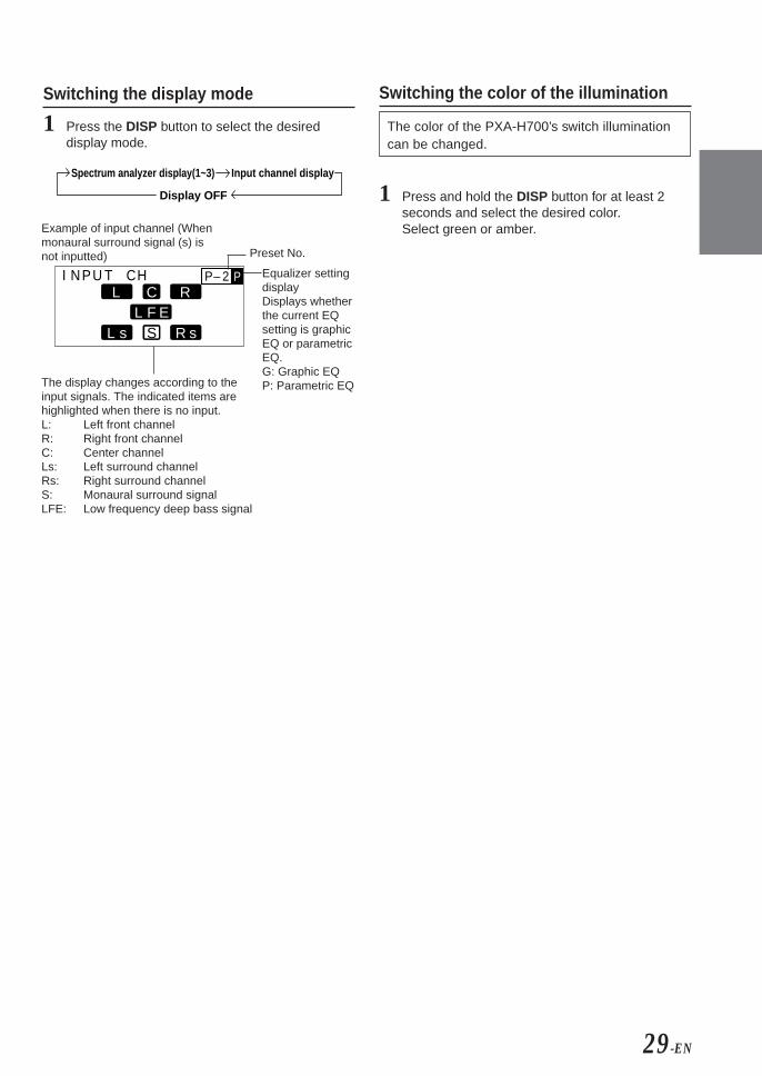
Switching the display mode
1 Press the DISP button to select the desireddisplay mode.
I NP HT C P– 2UL R
L s R sFL EC
P
S
Example of input channel (Whenmonaural surround signal (s) isnot inputted)
The display changes according to theinput signals. The indicated items arehighlighted when there is no input.L: Left front channelR: Right front channelC: Center channelLs: Left surround channelRs: Right surround channelS: Monaural surround signalLFE: Low frequency deep bass signal
Switching the color of the illumination
The color of the PXA-H700’s switch illuminationcan be changed.
1 Press and hold the DISP button for at least 2seconds and select the desired color.Select green or amber.
Input channel displaySpectrum analyzer display(1~3)
Display OFF
Preset No.
Equalizer settingdisplayDisplays whetherthe current EQsetting is graphicEQ or parametricEQ.G: Graphic EQP: Parametric EQ

30-EN
Installation and ConnectionsBefore installing or connecting the unit, pleaseread the following and pages 2 and 3 of thismanual thoroughly for proper use.
WarningDO NOT DISASSEMBLE OR ALTER.
Doing so may result in an accident, fire or electric shock.
USE THE CORRECT AMPERE RATING WHENREPLACING FUSES.
Failure to do so may result in fire or electric shock.
MAKE THE CORRECT CONNECTIONS.
Failure to make the proper connections may result in fireor product damage.
USE ONLY IN CARS WITH A 12 VOLT NEGATIVEGROUND.
(Check with your dealer if you are not sure.) Failure to doso may result in fire, etc.
BEFORE WIRING, DISCONNECT THE CABLE FROMTHE NEGATIVE BATTERY TERMINAL.
Failure to do so may result in electric shock or injury dueto electrical shorts.
DO NOT ALLOW CABLES TO BECOME ENTANGLEDIN SURROUNDING OBJECTS.
Arrange wiring and cables in compliance with the manualto prevent obstructions when driving. Cables or wiringthat obstruct or hang up on places such as the steeringwheel, gear lever, brake pedals, etc. can be extremelyhazardous.
DO NOT SPLICE INTO ELECTRICAL CABLES.
Never cut away cable insulation to supply power to otherequipment. Doing so will exceed the current carryingcapacity of the wire and result in fire or electric shock.
DO NOT DAMAGE PIPE OR WIRING WHENDRILLING HOLES.
When drilling holes in the chassis for installation, takeprecautions so as not to contact, damage or obstruct pipes,fuel lines, tanks or electrical wiring. Failure to take suchprecautions may result in fire.
DO NOT USE BOLTS OR NUTS IN THE BRAKE ORSTEERING SYSTEMS TO MAKE GROUNDCONNECTIONS.
Bolts or nuts used for the brake or steering systems (orany other safety-related system), or tanks should NEVERbe used for installations or ground connections. Usingsuch parts could disable control of the vehicle and causefire etc.
DO NOT INSTALL THE MONITOR NEAR THEPASSENGER SEAT AIR BAG.
If the unit is not installed correctly the air bag may notfunction correctly and when triggered the air bag maycause the monitor to spring upwards causing an accidentand injuries.
DO NOT BLOCK VENTS OR RADIATOR PANELS.
Doing so may cause heat to build up inside and may resultin fire.
KEEP SMALL OBJECTS SUCH AS BATTERIES OUTOF THE REACH OF CHILDREN.
Swallowing them may result in serious injury. Ifswallowed, consult a physician immediately.
DO NOT INSTALL IN LOCATIONS WHICH MIGHTHINDER VEHICLE OPERATION, SUCH AS THESTEERING WHEEL OR GEARSHIFT.
Doing so may obstruct forward vision or hampermovement etc. and results in serious accident.
CautionHAVE THE WIRING AND INSTALLATION DONE BYEXPERTS.
The wiring and installation of this unit requires specialtechnical skill and experience. To ensure safety, alwayscontact the dealer where you purchased this product tohave the work done.
USE SPECIFIED ACCESSORY PARTS AND INSTALLTHEM SECURELY.
Be sure to use only the specified accessory parts. Use ofother than designated parts may damage this unitinternally or may not securely install the unit in place.This may cause parts to become loose resulting in hazardsor product failure.

31-EN
FR
ES
DE
SE
IT
ARRANGE THE WIRING SO IT IS NOT CRIMPED ORPINCHED BY A SHARP METAL EDGE.
Route the cables and wiring away from moving parts (likethe seat rails) or sharp or pointed edges. This will preventcrimping and damage to the wiring. If wiring passesthrough a hole in metal, use a rubber grommet to preventthe wire’s insulation from being cut by the metal edge ofthe hole.
DO NOT INSTALL IN LOCATIONS WITH HIGHMOISTURE OR DUST.
Avoid installing the unit in locations with high incidenceof moisture or dust. Moisture or dust that penetrates intothis unit may result in product failure.
Precautions
• Be sure to disconnect the cable from the (–) batterypost before installing your PXA-H700. This willreduce any chance of damage to the unit in case of ashort-circuit.
• Be sure to connect the color coded leads according tothe diagram. Incorrect connections may cause the unitto malfunction or damage to the vehicle’s electricalsystem.
• When making connections to the vehicle’s electricalsystem, be aware of the factory installed components(e.g. on-board computer). Do not tap into these leads toprovide power for this unit. When connecting thePXA-H700 to the fuse box, make sure the fuse for theintended circuit of the PXA-H700 has the appropriateamperage. Failure to do so may result in damage to theunit and/or the vehicle. When in doubt, consult yourALPINE dealer.
• The PXA-H700 uses female RCA-type jacks forconnection to other units (e.g. amplifier) having RCAconnectors. You may need an adaptor to connect otherunits. If so, please contact your authorized ALPINEdealer for assistance.
Wiring ConnectionsImproper wiring connections could cause serious damageto your audio system. Be sure you:1. DO NOT connect (–) wires from left and right speakers
together.2. DO NOT ground any speaker wires.3. DO NOT run wires where they may be pinched or cut.4. DO NOT leave bare speaker terminals exposed. They
may contact the vehicle chassis and cause a short.
FuseWhen replacing the fuse(s), the replacement fuse must beof the same amperage as shown on the fuse holder. If thefuse(s) blows more than once, carefully check allelectrical connections for shorted circuitry. Also have yourvehicle’s voltage regulator checked. Do not attempt torepair the unit yourself; return it to your Alpine dealer ornearest Alpine Service Station for servicing.
TemperatureIn order to ensure proper performance, be sure thetemperature in your vehicle is above 14°F (–10°C) andbelow 140°F (60°C) before turning your unit on. Good aircirculation is essential to prevent internal heat build-up inthe unit.

32-EN
Installation and ConnectionsIMPORTANTPlease record the serial number of your unit inthe space provided below and keep it as apermanent record. The serial number plate islocated on the bottom of the unit.
SERIAL NUMBER:
INSTALLATION DATE:
INSTALLATION TECHNICIAN:
PLACE OF PURCHASE:
To prevent external noise from entering theaudio system.• Locate the unit and route the leads at least 10 cm away
from the car harness.• Keep the battery power leads as far away from other
leads as possible.• Connect the ground lead securely to a bare metal spot
(remove any paint, dirt or grease if necessary) of thecar chassis.
• If you add an optional noise suppressor, connect it asfar away from the unit as possible.Your Alpine dealer carries various noise suppressors.Contact them for further information.
• Your Alpine dealer knows best about noise preventionmeasures so consult your dealer for furtherinformation.
Accessories
Ai-NET cable Display cable
Connection Cable Velcro fastener formounting controlunit or base unit
Pan head screw(M3 x 5)
x 2
Microphone
Flat head screw(M5 x 8)
x 4
Flush mount
x 2
Self-tapping screw(M2.6 x 8)
x 4
Flanged self-tapping screw
(M4 x 14)
x 4 x 3
Mounting unit
1 set

33-EN
FR
ES
DE
SE
IT
Installation
The PXA-H700 is made up of two components: theControl Unit and Base Unit.
Mounting the control unit
CAUTION:Do not install the control unit near the air-bag of thefront passenger’s seat.• Confirm the installation location will be safe.• Determine the mounting position on the
dashboard. The area should be large enough tocenter the unit and reasonably flat.
Installation using Velcro fastener
1. Without separating the two pieces of Velcrofastener, peel off the paper backing on one sideand place on the back of the control unit.
2. Make sure the location selected is free frommoisture or dirt. Peel off the backing paper fromthe other side of the Velcro fastener on thecontrol.
3. Place the control unit on the mounting locationand press the unit firmly to mount securely.
Mounting other units
1 Remove the face plate.
2 Use a screwdriver, etc., to slide the locking pin,then take out the inner case.
3 Mount the control unit using the included screws.
4 Mount the previously removed inner case intothe dashboard. Slide the control unit into thecase.
<JAPANESE CAR>
1 After step 2 on “Mounting other units” of“Mounting the control unit”, remove the sidebracket.
2 Mount the control unit using the included screws.
Face plate
Inner case
Locking pin
Side bracket
Side bracket
Bracket
Spacer
Control unit
Pan head screw (M3 x 5) x 2
Pan head screw (M3 x 5) x 2
Control unit
Spacer
Bracket
Inner case
Face plate
Dashboard
Dashboard
Velcro fastener
Control unit
34-EN
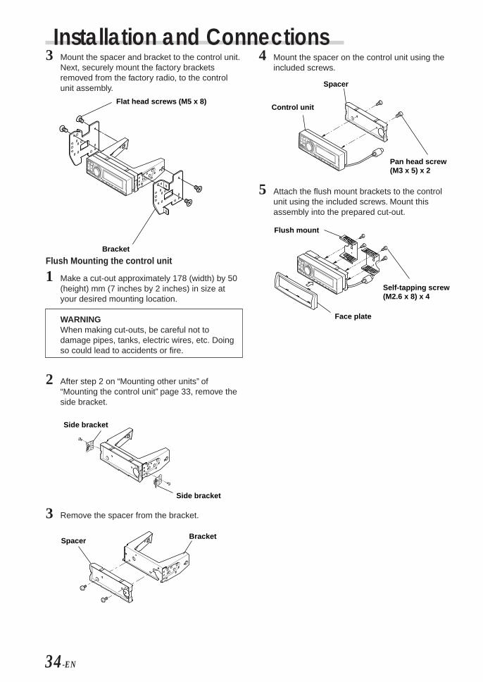
Installation and Connections3 Mount the spacer and bracket to the control unit.
Next, securely mount the factory bracketsremoved from the factory radio, to the controlunit assembly.
Flush Mounting the control unit
1 Make a cut-out approximately 178 (width) by 50(height) mm (7 inches by 2 inches) in size atyour desired mounting location.
WARNINGWhen making cut-outs, be careful not todamage pipes, tanks, electric wires, etc. Doingso could lead to accidents or fire.
2 After step 2 on “Mounting other units” of“Mounting the control unit” page 33, remove theside bracket.
3 Remove the spacer from the bracket.
Side bracket
Side bracket
Spacer Bracket
4 Mount the spacer on the control unit using theincluded screws.
5 Attach the flush mount brackets to the controlunit using the included screws. Mount thisassembly into the prepared cut-out.
Flush mount
Face plate
Self-tapping screw(M2.6 x 8) x 4
Flat head screws (M5 x 8)
Bracket
Control unit
Spacer
Pan head screw (M3 x 5) x 2

35-EN
FR
ES
DE
SE
IT
Mounting the base unit
● Velcro Fastener Mounting
Attach to the vehicle (such as under thedashboard).
Flanged self-tapping screw (M4 x 14)
Velcro fastener
● Using the Mounting Screws (Supplied)The Base Unit can be mounted under the seatusing the mounting screws.
1 Decide on the installation location.• The trunk, etc., is the best place.
2 Mark the positions of the mounting screws at thechosen location.
3 Drill 3 mm (1/8”) holes or smaller.
WARNINGWhen making holes, be careful not to damagepipes, tanks, electric wires, etc. Doing so couldlead to accidents or fire.
4 Securely mount the unit using the four includedflanged self-tapping screws (M4 x 14).

36-EN
Installation and ConnectionsBasic Connections Diagram
Display
Cord colors and cord/terminal specifications Connect to:
• Front 1 speaker output jacks (RCA outputs)Outputs signals for driving the front 1 speakers.
• Front 2 speaker output jacks (RCA outputs)Outputs signals for driving the front 2 speakers.
• Rear speaker output jacks (RCA outputs)Outputs signals for driving the rear speakers.
• Subwoofer output jack (RCA outputs)Outputs signals for driving the subwoofer.
• Center speaker or subwoofer output jack (RCA output)Outputs signals for driving the center speaker or subwoofer.
• Navigation audio input jack (RCA input)Used to input the audio output signals of a navigation system.
Connect to the amplifier for the front 1speaker.
Connect to the amplifier for the front 2speaker.
Connect to the amplifier for the rear speaker.
Connect to the amplifier for the subwoofer.
Connect to the amplifier for the center speaker or subwoofer.
Used for automatic adjustment.• Microphone jack
Use this to connect a microphone.
Connect to the navigation system.
Connect to an Ai-NET product using an Ai-NET cord.For connection to the PXA-H700, use the straight side.
• Changer input terminal (Ai-NET input)Used for system expansion (Ai-NET changer, etc.).
Connect to an Ai-NET product using an Ai-NET cord.For connection to the PXA-H700, use the straight side.
Used for RCA connections.Connect to the head unit.
• Ai-NET input terminal (Ai-NET input)Used for system expansion (DVD player, etc.).
• Audio input jacks (RCA inputs)Used to input the audio output signals of a head unit connected with RCA connections to the PXA-H700.
• Remote ON cableConnect to the head unit for RCA connections.(Non Ai-NET connection)
• Remote OUT cableConnect to the amplifier or other peripheral device.
• Guide control cableUsed to interrupt the navigation system’s sound.
• Ground cableConnect securely to a metal part of the vehicle’s body.
• Battery power cablePower is supplied constantly to the PXA-H700 regardless of whether the engine key is on or off.
Used for RCA connections.(Non Ai-NET connection)
Used to add an amplifier.
Connect to the navigation system.
Connect to the vehicle’s body.
Connect this lead to the positive(+) post of the vehicle's battery.
Blue/White
Blue/White
White/Green
Yellow
Fuse
(3A)
Black
Terminal specifications Connect to:
Connect to an Ai-NET product using an optical fiber cable.
• Head unit input terminal (optical digital input)Used for system expansion (Ai-NET head unit, etc.).
Connect to an Ai-NET product using an optical fiber cable.
• Changer input terminal (optical digital input)Used for system expansion (Ai-NET changer, etc.).
Connect to an Ai-NET product using an optical fiber cable.
• DVD player input terminal (optical digital input)Used for system expansion (DVD player, etc.).
(L)
(R)
FRONT 1(FULL RANGE
/TWEETER)
FRONT 2 REAR SUBWOOFER
CONTROL UNIT
MICCHG
DIGITAL 2CD
DIGITAL 1DVD
DIGITAL 3
GUIDEINPUTOUTPUT
CENTER
SELECTABLESUBWOOFER
(L) (R) Ai–NET INANALOG 2ANALOG 1
CHANGER INANALOG 3
POWER SUPPLY
CAUTIONDo not connect or disconnect thedisplay cable when the power of theunit is on.

37-EN
FR
ES
DE
SE
IT
Examples of system expansion
Battery
Blue/White
Blue/White
White/green
Not used in this system
Not used in this system
To External Amplifier Remote ON Cable
Connect to a metal part of chassis body with a screw.
Remote OUT Cable
Remote ON Cable
Guide Control Cable
Grounding Cable
Battery Power Cable
Rear Output (L)Rear Output (R)
Center Output or Subwoofer Output (L)*Subwoofer Output or Subwoofer Output (R)*
Front 1 Output (L)Front 1 Output (R)
Front 2 Output (L)Front 2 Output (R)
Ai-NET Cable (Included with DVD Changer)
Ai-NET Cable (Included)DVD Changer
Monitor(TME-M790 etc.)
Ai-NET CompatibleHead Unit
EQ
/DIV
System Switch
Fiber Optic Cable (Included with DVD Changer)RCA Connection Cable
To Video Input Jack
To Video Output Jack
Remote Control Output CableRemote Control Input Cable
Fiber Optic Cable (Sold Separately)
(White/Brown)(White/Brown)
★
To External Amplifier
(L)
(R)
FRONT 1(FULL RANGE
/TWEETER)
FRONT 2 REAR SUBWOOFER
CONTROL UNIT
MIC
GUIDEINPUTOUTPUT (L) (R) Ai–NET INANALOG 2ANALOG 1
CHANGER INANALOG 3
POWER SUPPLY
CHGDIGITAL 2
CDDIGITAL 1
DVDDIGITAL 3
CENTER
SELECTABLESUBWOOFER
NOTEPlease observe the following when using Fiber Optic Cable.• Do not coil the Fiber Optic Cable smaller than a 30mm radius.• Do not place anything on top of the Fiber Optic Cable.
NOTE★ Used for connection to an optical digital
compatible head unit.
• PXA-H700 + Ai-NET Compatible Head Unit + DVD Changer +Monitor + External Amplifier
* When the subwoofer is connected to thecenter speaker output jack, it becomessubwoofer output (L or R).In this case, change the setting of the centerspeaker to subwoofer in “Setting the speakers”(page 4).

38-EN
Installation and Connections
NOTEPlease observe the following when using Fiber Optic Cable.• Do not coil the Fiber Optic Cable smaller than a 30mm radius.• Do not place anything on top of the Fiber Optic Cable.
• PXA-H700 + Ai-NET Compatible Head Unit + CD Changer +External Amplifier
Battery
Blue/White
Blue/White
White/green
Not used in this system
Not used in this system
To External Amplifier Remote ON Cable
Connect to a metal part of chassis body with a screw.
Remote OUT Cable
Remote ON Cable
Guide Control Cable
Grounding Cable
Battery Power Cable
Rear Output (L)Rear Output (R)
Ai-NET Cable (Included with CD Changer)
Ai-NET Cable (Included)
Ai-NET CompatibleHead Unit
EQ
/DIV
System Switch
Fiber Optic Cable (Sold Separately)
Ai-NET CompatibleCD Changer
★★★
Fiber Optic Cable (Sold Separately) ★★
★
Front 1 Output (L)Front 1 Output (R)
Front 2 Output (L)Front 2 Output (R)
Center Output or Subwoofer Output (L)*Subwoofer Output or Subwoofer Output (R)*
To External Amplifier
(L)
(R)
FRONT 1(FULL RANGE
/TWEETER)
FRONT 2 REAR SUBWOOFER
CONTROL UNIT
MIC
GUIDEINPUTOUTPUT (L) (R) Ai–NET INANALOG 2ANALOG 1
CHANGER INANALOG 3
POWER SUPPLY
CHGDIGITAL 2
CDDIGITAL 1
DVDDIGITAL 3
CENTER
SELECTABLESUBWOOFER
NOTES★ When connecting a Optical Digital CD
Changer★★ Used for connection to an optical
digital compatible head unit.★★★ When connecting a Optical Digital CD
Changer, change the Digital/Analogswitch of the CD Changer to "2"(Digital Output)
1 2
* When the subwoofer is connected to thecenter speaker output jack, it becomessubwoofer output (L or R).In this case, change the setting of the centerspeaker to subwoofer in “Setting the speakers”(page 4).

39-EN
FR
ES
DE
SE
IT
• PXA-H700 + Head Unit + Video Deck etc. + External Amplifier• For connecting a head unit with which Ai-NET connections are not possible.
NOTEWhen using the PXA-H700 with a non-Ai-NET head unit, +12V is required on this line * to turn on the equalizer. If yourhead unit does not have a remote-on or power-antenna turn-on wire, an SPST switch must be connected between anignition source and this terminal. The PXA-H700 can then be turned on using this switch.The PXA-H700 can be used with any head unit. However, only an Alpine Ai-NET compatible head unit will be able totake full advantage of all the features and functions of this processor.
Battery
Blue/White
White/greenNot used in this system
To External Amplifier Remote ON Cable
Connect to a metal part of chassis body with a screw.
Remote OUT Cable
Guide Control Cable
Grounding Cable
Battery Power Cable
Rear Output (L)Rear Output (R)
RCA connection cable
Remote OUT cable
RCA connection cable
*Remote ON Cable
Head Unit
Ai-RCA Conversion Cable(Sold Separately)
TV Tuner,Video etc.
AudioOutput
Blue/WhiteBlue/White
Front 1 Output (L)Front 1 Output (R)
Front 2 Output (L)Front 2 Output (R)
Center Output or Subwoofer Output (L)*Subwoofer Output or Subwoofer Output (R)*
To External Amplifier
(L)
(R)
FRONT 1(FULL RANGE
/TWEETER)
FRONT 2 REAR SUBWOOFER
CONTROL UNIT
MIC
GUIDEINPUTOUTPUT (L) (R) Ai–NET INANALOG 2ANALOG 1
CHANGER INANALOG 3
POWER SUPPLY
CHGDIGITAL 2
CDDIGITAL 1
DVDDIGITAL 3
CENTER
SELECTABLESUBWOOFER
* When the subwoofer is connected to thecenter speaker output jack, it becomessubwoofer output (L or R).In this case, change the setting of the centerspeaker to subwoofer in “Setting the speakers”(page 4).

40-EN
Installation and Connections• PXA-H700 + DVA-7996 Head Unit + CD Changer + Navigation
System + Monitor + External Amplifier
NOTEDepending on the type of monitor used in the system, a separateRGB conversion cable (KWE-503N) may be required. In addition,connections are different from the ones shown above whenconnecting to an all-purpose monitor. Also refer to the operatinginstructions of the KCE-900E. For details, contact your store ofpurchase or an Alpine Information Center.Please observe the following when using Fiber OpticCable.• Do not coil the Fiber Optic Cable smaller than a 30mm radius.• Do not place anything on top of the Fiber Optic Cable.
Battery
NAVIGATION INPUT
REMOTE INPUT
VIDEO OUTPUTRGB
RGB OUTPUTGUIDE OUTPUTNTSC VIDEO
OUTPUT
NTSC
Blue/White
Blue/WhiteNot used in this system
To External Amplifier Remote ON Cable
Connect to a metal part of chassis body with a screw.
Remote OUT Cable
Remote ON Cable
Grounding Cable
Battery Power Cable
Rear Output (L)Rear Output (R)
RCA connection cable
To Video Input Jack
RGB Cable (Sold Separately)
Remote ControlOutput Cable
Remote Control Input Cable
Video Output Cable
Guide Control Cable
Yellow
Navigation
KCE-900E (Sold Separately)
DVA-7996Head Unit
Fiber Optic Cable (Sold Separately)
Monitor(TME-M790 etc.)
White/Green
White/Brown White/Brown
Front 1 Output (L)Front 1 Output (R)
Front 2 Output (L)Front 2 Output (R)
RCA connection cable
Guide Control CableWhite/Green
Ai-NET CompatibleCD Changer
★★
Ai-NET Cable(Included with CD Changer)
Fiber Optic Cable(Sold Separately)
Ai-NET Cable (Included)
★
Center Output or Subwoofer Output (L)*Subwoofer Output or Subwoofer Output (R)*
To External Amplifier
(L)
(R)
FRONT 1(FULL RANGE
/TWEETER)
FRONT 2 REAR SUBWOOFER
CONTROL UNIT
MIC
GUIDEINPUTOUTPUT (L) (R) Ai–NET INANALOG 2ANALOG 1
CHANGER INANALOG 3
POWER SUPPLY
CHGDIGITAL 2
CDDIGITAL 1
DVDDIGITAL 3
CENTER
SELECTABLESUBWOOFER
NOTES★ When connecting a Optical Digital CD
Changer★★ When connecting a Optical
Digital CD Changer, changethe Digital/Analog switch ofthe CD Changer to “2”(Digital Output)
1 2
* When the subwoofer is connected to thecenter speaker output jack, it becomessubwoofer output (L or R).In this case, change the setting of thecenter speaker to subwoofer in “Settingthe speakers” (page 4).

41-EN
EN
FR
ES
DE
SE
IT
InformationTerminology
Dolby DigitalDolby Digital is a digital audio compressiontechnology developed by Dolby Laboratories thatallows large quantities of audio data to be efficientlyrecorded on discs. It is compatible with audio signalsfrom mono (1 channel) all the way up to 5.1-channelsurround sound. The signals for the differentchannels are completely independent, and since thesound is high quality digital there is no loss of soundquality.
Centerspeaker
Frontspeakers
Rearspeakers
Subwoofer
Speaker layout for enjoyingDolby Digital sound/DTS sound
DTSThis is a home-use digital sound format of the DTSSound System. This is a high quality sound system,developed by Digital Theater Systems Corp for usein movie theaters.DTS has six independent sound tracks. The theaterpresentation is fully realized in the home and othersettings. DTS is the abbreviation for Digital TheaterSystems.
Dolby Pro Logic IIDolby Pro Logic II provides multichannel surroundsound from any 2 channel source. It reproducesextended bandwidth playback with 5.1 channels.This is made possible by an advanced matrixsurround decoder. This new decoder is able to drawout spatial characteristics of the recording withoutadding tonal coloration or artificial delays that did notexist in the original.
Linear PCM audio (LPCM)LPCM is a signal recording format used for musicCDs. Whereas music CDs are recorded at 44.1 kHz/16 bits, DVDs are recorded at 48 kHz/16 bits to 96kHz/24 bits, thereby achieving higher sound qualitythan music CDs.

42-EN
In case of difficulty
If you encounter a problem, please review the itemsin the following checklist. This guide will help youisolate the problem if the unit is at fault. Otherwise,make sure the rest of your system is properlyconnected or consult your authorized Alpine dealer.
Set does not operate.Nothing appears on the display.• Vehicle’s ignition key is turned off.
- Turn the vehicle’s ignition key on.• Set’s power is not turned on.
- Turn the vehicle’s ignition key on then turn onthe power of the head unit.
• Power cord is not securely connected.- Connect the power cord securely.
• Fuse is blown.- Replace with a fuse of the specified capacity.
• Display mode is set to off.- Switch the display to another mode.
(Page 29)
Power is on but no sound is produced.• Volume level is set to the minimum.
- Increase the volume level. (Page 5)• Input mode is set to a mode to which nothing is
connected.- Set to a connected mode. (Page 5)
No sound is produced from the speakers.• Cords are not securely connected.
- Connect the cords securely.• Speaker is set to the off mode.
- Set the speaker to the on mode. (Pages 4and 22)
Speaker setup settings cannot be made.• Front speakers are set to “SMALL”.
- Set the front speakers to “LARGE”. (Page 22)
Sound cannot be adjusted.• Defeat is set to the on mode.
- Set defeat to the off mode. (Page 28)
OthersCaution when connecting the DVA-5205/DVA-5200/DHA-S680Although the adjustment screen such as EQ andTCR on the audio processor are available in DVA-5205/DVA-5200/DHA-S680, these adjustmentscannot be made when they are connected to thePXA-H700.

43-EN
EN
FR
ES
DE
SE
IT
Specifications
Graphic EQ number of bands:Front (left and right) 31 bandsRear (left and right) 31 bandsCenter 31 bandsSubwoofer 10 bands
Graphic EQ boost cutrange: ±9 dBParametric EQ number of bands:
Front/rear/center 5 bandsSubwoofer 2 bands
Parametric EQ frequency: Front, Rear and Center
Band 1: 20/22/25/28/31.5/36/40/45/50/56/63/71/80/90/100/110/125/140/160/180/200/220/250/280/315/360/400/450/500 (Hz)
Band 2: 50/56/63/71/80/90/100/110/125/140/160/180/200/220/250/280/315/360/400/450/500/560/630/710/800/900/1k/1.1k/1.2k (Hz)
Band 3: 125/140/160/180/200/220/250/280/315/360/400/450/500/560/630/710/800/900/1k/1.1k/1.2k/1.4k/1.6k/1.8k/2k/2.2k/2.5k/2.8k/3.2k (Hz)
Band 4: 315/360/400/450/500/560/630/710/800/900/1k/1.1k/1.2k/1.4k/1.6k/1.8k/2k/2.2k/2.5k/2.8k/3.2k/3.6k/4k/4.5k/5k/5.6k/6.3k/7.1k/8k (Hz)
Band 5: 800/900/1k/1.1k/1.2k/1.4k/1.6k/1.8k/2k/2.2k/2.5k/2.8k/3.2k/3.6k/4k/4.5k/5k/5.6k/6.3k/7.1k/8k/9k/10k/11k/12.5k/14k/16k/18k/20k (Hz)
SubwooferBand 1: 20/22/25/28/31.5/36/40/45/50/56/
63/71/80 (Hz)Band 2: 50/56/63/71/80/90/100/110/125/
140/160/180/200 (Hz)Parametric EQ boost cutrange: ±9 dBTime correction controlrange: 0 to 20 ms (0.05 ms steps)Frequency response: 20 Hz to 20 kHzS/N ratio: 95 dBChannel separation: 70 dBInput sensitivity: 850 mA (2V for analog 1 only)Subwoofer crossover: 20 to 200 Hz (1/6 oct. steps)Rated output: 4V (with 10 k ohms load)Input impedance: 10 k ohms or greaterOutput impedance: 1 k ohm or lessWeight: Control unit 159 g (5 oz)
Base unit 1.1 kg (2 lbs. 6 oz)
DimensionsControl unit
Width 170 mm (6-3/4")Height 46 mm (1-13/16")Depth 24 mm (15/16")
Base unitWidth 260 mm (10-3/16")Height 40 mm (1-9/16")Depth 160 mm (6-1/4")
<Components>
Parts name Quantity
Parts for mounting ................................ 1setOwner’s manual .................................... 1setMicrophone ........................................... 1set
Due to continuous product improvement,specifications and design are subject to changewithout notice.The illustrations included in these instructions mayappear different from the actual product due toprinting conditions.
Manufactured under license from Dolby Laboratories.“Dolby”, “Pro Logic” and the double-D symbol aretrademarks of Dolby Laboratories. Confidentialunpublished works. ©1992-1997 Dolby Laboratories.All rights reserved.
Manufactured under license from Digital TheaterSystems, Inc. US Pat. No. 5,451,942 and otherworldwide patents issues and pending. “DTS” and“DTS Digital Surround” are trademarks of DigitalTheater Systems, Inc. © 1996 Digital TheaterSystems, Inc. All rights reserved.


Fidèles à leur engagement de ne fournir que des produits de qualité, ALPINE ELECTRONIQUE DE L'AMERIQUE INC. etALPINE ELECTRONIQUE DU CANADA INC. (Alpine) sont heureuses de vous offrir cette garantie. Nous vous suggérons de lelire attentivement et en entier. Si vous avez la moindre question, veuillez contacter l'un de nos concessionnaires ou appelerdirectement Alpine au numéros Liste ci-dessous.
2 Vous devez donner une description détaillée desproblèmes qui sont à l'origine de votre demande deréparation.
3 Vous devez joindre la preuve de votre achat du produit.4 Vous devez emballer soigneusement le produit pour éviter
tout dommage durant son transport.
● LIMITATION DES GARANTIES TACITESLA DURÉE DE TOUTES LES GARANTIES TACITES, YCOMPRIS LA GARANTIE D'ADAPTATION A L'UTILISATIONET LA GARANTIE DE QUALITÉ LOYALE ET MARCHANDE,EST LIMITÉE À CELLE DE LA GARANTIE EXPRESSEDÉTERMINÉE CI-DESSUS. PERSONNE N'EST AUTORISÉÀ ENGAGER AUTREMENT LA RESPONSABILITÉ D'ALPINEEN VERTU DE LA VENTE D'UN PRODUIT.
● EXCLUSIONS DE LA GARANTIEALPINE STIPULE EXPRESSÉMENT QU'ELLE N'EST PASRESPONSABLE DES DOMMAGES DOMMAGES-INTÉRÊTSET DOMMAGES INDIRECTS PROVOQUÉS PAR LEPRODUIT. LES DOMMAGES DOMMAGES-INTÉRÊTSSONT LES FRAIS DE TRANSPORT DU PRODUIT VERS UNCENTRE DE SERVICE ALPINE, LA PERTE DE TEMPS DEL'ACHETEUR ORIGINAL, LA PERTE D'UTILISATION DUPRODUIT, LES BILLETS D'AUTOBUS, LA LOCATION DEVOITURES ET TOUS LES AUTRES FRAIS LIÉS À LAGARDE DU PRODUIT.LES DOMMAGES INDIRECTS SONT LES FRAIS DERÉPARATION OU DE REMPLACEMENT D'AUTRES BIENSENDOMMAGÉS SUITE AU MAUVAIS FONCTIONNEMENTDU PRODUIT.LES RECOURS PRÉVUS PAR LES PRÉSENTESEXCLUENT ET REMPLACENT TOUTE AUTRE FORME DERECOURS.
● LIEN ENTRE LA GARANTIE ET LA LOILa garantie vous donne des droits spécifiques, mais vouspouvez aussi jouir d'autres droits, qui varient d'un état oud'une province à l'autre. En outre, certains états et certainesprovinces interdisent de limiter la durée des garanties tacitesou d'exclure les dommages accessoires ou indirects. Dans cecas, les limites et les exclusions de la garantie peuvent ne pass'appliquer à vous.
● CLAUSE APPLICABLE AU CANADA SEULEMENTPour que la garantie soit valable, il faut qu'un centred'installation autorisé ait installé le système audio pour l'autodans votre véhicule et qu'il ait ensuite apposé son cachet surla garantie.
● NUMÉROS D'APPEL DU SERVICE À LA CLIENTELESi vous avez besoin de nos services, veuillez appeler lecentre de service autorisé Alpine le plus proche.
U.S.A. 1-800-ALPINE-1 (1-800-257-4631)CANADA 1-800-ALPINE-1 (1-800-257-4631)
● PRODUITS COUVERT PAR LA GARANTIECette garantie couvre les produits audio/visuel de voiture etles accessoires connexes ("le produit"). Elle ne couvre lesproduits que dans le pays où il ont été achetés.
● DURÉE DE LA GARANTIECette garantie est en vigueur pendant un an à partir de la datedu premier achat du client.
● GARANTIE À VIE DES TÊTES DE LECTURE DESMAGNÉTOPHONES À CASSETTES
Toutes les têtes de cassettes analogiques audio de voitureAlpine, à l’exception des êtes de cassettes vidéo sontgaranties à vie contre des vices de fabrication pouvantentraîner leur panne.
● PERSONNES PROTÉGÉES PAR LA GARANTIESeul l'acheteur original du produit, s'il résisde aux États-Unis,à Porto Rico ou au Canada, peut se prévaloir de la garantie.
● CE QUI EST COUVERTCette garantie couvre tous les défauts de matériaux et defabrication (pièces et main d'œuvre) du produit.
● CE QUI N'EST PAS COUVERTCette garantie ne couvre pas ce qui suit:1 Les dommages survenus durant le transport des produits
renvoyés à Alpine pour être réparés (les réclamationsdoivent être adressées au transporteur);
2 Tout dégât provoqué par accident, abus, négligence,usage inapproprié, mauvais raccordement, mauvaiseutilisation ou par le non-respect des instructionsindiquées dans le manuel de l’utilisateur.
3 Les dommages dus à la force majeure, notamment auxtremblements de terre, au feu, aux inondations, auxtempêtes ou aux autres cataclysmes naturels;
4 Les frais ou les dépenses relatifs à l'enlèvement ou à laréinstallation du produit;
5 Les services rendus par une personne, physique oumorale non autorisée;
6 Les produits dont le numéro de série a été effacé, modifiéou retiré;
7 Les produits qui ont été adaptés ou modifiés sans leconsentement d'Alpine;
8 Les produits qui ne sont pas distribués par Alpine auxEtats-Unis, à Porto Rico ou au Canada;
9 Les produits qui n'ont pas été achetés par l'entremise d'unconcessionnaire Alpine autorisé;
p Tout produit qui a été déterminé comme contenant unequantité excessive de poussière ou de saleté et toutproduit qui contient d’autres saleté, en ce compris duliquide et des corps étrangers.
● COMMENT SE PRÉVALOIR DE LA GARANTIE1 Il vous faut remettre le produit nécessitant des réparations
à un centre de service autorisé Alpine ou à Alpine même eten assumer les frais de transport. Alpine a le choix entreréparer le produit ou le remplacer par un produit neuf ourévisé, le tout sans frais pour vous. Si les réparations sontcouvertes par la garantie et si le produit a été envoyé à uncentre de service Alpine ou à Alpine, le paiement des fraisde réexpédition du produit incombe Alpine.
Alpine Électronique de L'Amérique, Inc., 19145 Gramercy Place, Torrance, California 90501, U.S.A.Alpine Électronique du Canada, Inc., Suite 203, 7300 Warden Ave. Markham, Ontario L3R 9Z6, Canada
GARANTIE LIMITÉE

ALPINE ELECTRONICS OF AMERICA, INC. AND ALPINE OF CANADA INC. ("Alpine"), are dedicated to qualitycraftsmanship and are pleased to offer this Warranty. We suggest that you read it thoroughly. Should you have anyquestions, please contact your Dealer or Alpine at one of the telephone numbers listed below.
● PRODUCTS COVERED:This Warranty covers Car Audio/Visual Products andRelated Accessories ("the product"). Products purchased inthe Canada are covered only in the Canada. Productspurchased in the U.S.A. are covered only in the U.S.A.
● LENGTH OF WARRANTY:This Warranty is in effect for one year from the date of thefirst consumer purchase.
● LIFETIME TAPE HEAD WARRANTY:All Alpine Car Audio analog tape heads excluding Videotape heads are warranted for life against manufacturingdefects causing failure.
● WHO IS COVERED:This Warranty only covers the original purchaser of theproduct, who must reside in the United States, Puerto Ricoor Canada.
● WHAT IS COVERED:This Warranty covers defects in materials or workmanship(parts and labor) in the product.
● WHAT IS NOT COVERED:This Warranty does not cover the following:1 Damage occurring during shipment of the product to
Alpine for repair (claims must be presented to thecarrier).
2 Damage caused by accident, abuse, negligence,misuse, improper connections, improper operation orfailure to follow instructions contained in the Owner'smanual.
3 Damage caused by act of God, including withoutlimitation, earthquake, fire, flood, storms or other acts ofnature.
4 Any cost or expense related to the removal orreinstallation of the product.
5 Service performed by an unauthorized person, companyor association.
6 Any product which has the serial number defaced,altered or removed.
7 Any product which has been adjusted, altered ormodified without Alpine's consent.
8 Any product not distributed by Alpine within the UnitedStates, Puerto Rico or Canada.
9 Any product not purchased from an Authorized AlpineDealer.
p Any product that has been determined to contain anexcessive amount of dust or dirt and any product thatcontains other contaminants including liquid or foreignobjects.
● HOW TO OBTAIN WARRANTY SERVICE:1 You are responsible for delivery of the product to an
Authorized Alpine Service Center or Alpine for repairand for payment of any initial shipping charges. Alpinewill, at its option, repair or replace the product with anew or reconditioned product without charge. If therepairs are covered by the warranty, and if the productwas shipped to an Authorized Alpine Service Center orAlpine, Alpine will pay the return shipping charges.
2 You should provide a detailed description of theproblem(s) for which service is required.
3 You must supply proof of your purchase of the product.4 You must package the product securely to avoid
damage during shipment.
● HOW WE LIMIT IMPLIED WARRANTIES:ANY IMPLIED WARRANTIES INCLUDING FITNESS FORUSE AND MERCHANTABILITY ARE LIMITED INDURATION TO THE PERIOD OF THE EXPRESSWARRANTY SET FORTH ABOVE AND NO PERSON ISAUTHORIZED TO ASSUME FOR ALPINE ANY OTHERLIABILITY IN CONNECTION WITH THE SALE OF THEPRODUCT.
● HOW WE EXCLUDE CERTAIN DAMAGES:ALPINE EXPRESSLY DISCLAIMS LIABILITY FORINCIDENTAL AND CONSEQUENTIAL DAMAGESCAUSED BY THE PRODUCT. THE TERM "INCIDENTALDAMAGES" REFERS TO EXPENSES OFTRANSPORTING THE PRODUCT TO THE ALPINESERVICE CENTER, LOSS OF THE ORIGINALPURCHASER'S TIME, LOSS OF THE USE OF THEPRODUCT, BUS FARES, CAR RENTALS OR OTHERSCOSTS RELATING TO THE CARE AND CUSTODY OFTHE PRODUCT. THE TERM "CONSEQUENTIALDAMAGES" REFERS TO THE COST OF REPAIRING ORREPLACING OTHER PROPERTY WHICH IS DAMAGEDWHEN THIS PRODUCT DOES NOT WORK PROPERLY.THE REMEDIES PROVIDED UNDER THIS WARRANTYARE EXCLUSIVE AND IN LIEU OF ALL OTHERS.
● HOW STATE/PROVINCIAL LAW RELATES TO THEWARRANTY:
This Warranty gives you specific legal rights, and you mayalso have other rights which vary form state to state andprovince to province. In addition, some states/provinces donot allow limitations on how long an implied warranty lasts,and some do not allow the exclusion or limitation ofincidental or consequential damages. Accordingly,limitations as to these matters contained herein may notapply to you.
● IN CANADA ONLY:This Warranty is not valid unless your Alpine car audioproduct has been installed in your vehicle by an AuthorizedInstallation Center, and this warranty stamped uponinstallation by the installation center.
● HOW TO CONTACT CUSTOMER SERVICE:Should the product require service, please call the followingnumber for your nearest Authorized Alpine Service Center.
U.S.A. 1-800-ALPINE-1 (1-800-257-4631)CANADA 1-800-ALPINE-1 (1-800-257-4631)
Alpine Electronics of America, Inc., 19145 Gramercy Place, Torrance, California 90501, U.S.A.Alpine Electronics of Canada, Inc., Suite 203, 7300 Warden Ave. Markham, Ontario, L3R 9Z6, Canada
LIMITED WARRANTY